

Full Size Tumble Action Washers
Before beginning installation, carefully read these instructions. This will simpfify the
installation and ensure the washer is installed correctly and safely. Leave these instructions
near the washer after installation for future reference.
NOTE: The electrical service to the washer must conform with local codes and ordinances
and the latest edition of the National Electrical Code, ANS!/NFPA 70.
Contents
For your safety the information in
this manual must be followed to minimize the risk
of fire or explosion or to prevent property damage,
personal injury or loss of life.
- Do not store or use gasoline or other flammable
vapors and liquid in the vicinity of this or any
other appliance.
- WHAT TO DO IF YOU SMELL GAS
• Do not try to light any appliance.
• Do not touch any electrical switch; do not
use any phone in your building.
• Clear the room, building or area of all
occupants.
• Immediately call your gas supplier from a
neighbor's phone. Follow the gas suppliers
instructions.
• If you cannot reach your gas supplier, call
the fire department.
S UBJECT PAGE
Pre-lnstallation Requirements 2
Electrical Requirements 2
Grounding Requirements 2
Water Supply Requirements 2
Drain Requirements 2
Rough-In Dimensions 3
Location Of Your Washer 4
Unpacking 4-5
Installation B-6
Replacement Parts 6
Installation and service must be performed by a
qualified installer, service agency or the gas
supplier.
Printed in U.S.A.
WN 134965500(0708)
PRE-INSTALLAT!ON REQUIREMENTS
Tools Required for Installation:
I. Phillips screwdriver
2. 10 mm socketwith ratchet.
3. Channel-lock adjustable pliers.
4. Carpenter's level.
absence of local codes, with the National Electrical
Codes, ANSI/NFPA 70 (latest edition). If in doubt,
call a licensed electrician. DO NOTcut off or alter
the grounding prong on the power supply cord. In
situations where a two-slot receptacle is present,
it is the owner's responsibility to have a licensed
electrician replace it with a properly grounded
three prong grounding type receptacle.
ELECTRICAL REQUIREMENTS
CIRCUIT- Individual, properly polarized and grounded
15 amp. branch circuit fused with 15 amp. time delay
fuse or circuit breaker.
POWER SUPPLY- 2 wire, with ground, 120 volt, single
phase, 60 Hz, Alternating Current. NOTE: Becauseof
potential inconsistent voltage capabilities, the useof this
washer with power created by gas powered generators,
solar powered generators, wind powered generators or
any other generator other than the local utility company
isnot recommended.
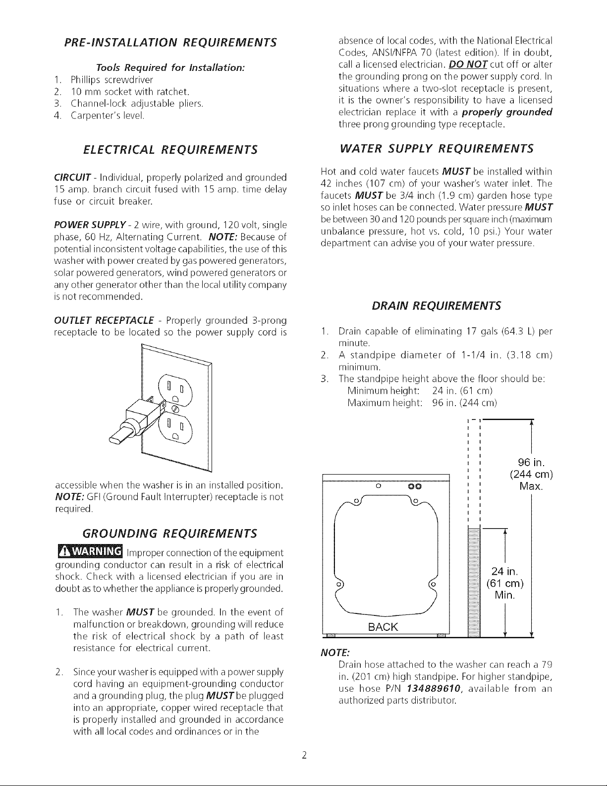
OUTLET RECEPTACLE - Properly grounded 3-prong
receptacle to be located so the power supply cord is
WATER SUPPLY REQUIREMENTS
Hot and cold water faucets MUST be installed within
42 inches (107 cm) of your washer's water inlet. The
faucets MUST be 3/4 inch (1.9 cm) garden hose type
so inlet hoses can be connected. Water pressure MUST
be between 30 and 120 pounds persquareinch (maximum
unbalance pressure, hot vs. cold, 10 psi.) Your water
department can advise you of your water pressure.
DRAIN REQUIREMENTS
I. Drain capable of eliminating 17 gals (64.3 L) per
minute.
2. A standpipe diameter of I-I/4 in. (3.18 cm)
minimum.
3. The standpipe height above the floor should be:
Minimum height: 24 in. (61 cm)
Maximum height: 96 in. (244cm)
accessible when the washer is in an installed position.
NOTE: GFI(Ground Fault Interrupter) receptacle is not
required.
GROUNDING REQUIREMENTS
Improper connection of the equipment
grounding conductor can result in a risk of electrical
shock. Check with a licensed electrician if you are in
doubt asto whether the appliance isproperly grounded.
.
The washer MUST be grounded. In the event of
malfunction or breakdown, grounding will reduce
the risk of electrical shock by a path of least
resistance for electrical current.
.
Sinceyour washer is equipped with a power supply
cord having an equipment-grounding conductor
and a grounding plug, the plug MUSTbe plugged
into an appropriate, copper wired receptacle that
is properly installed and grounded in accordance
with all local codes and ordinances or in the
o OO
T
24 in.
(61 cm)
Min.
BACK
I I
NOTE:
Drain hose attached to the washer can reach a 79
in. (201 cm) high standpipe. For higher standpipe,
use hose P/N 134889610, available from an
authorized parts distributor.
l
r
96 in.
(244 cm)
Max.
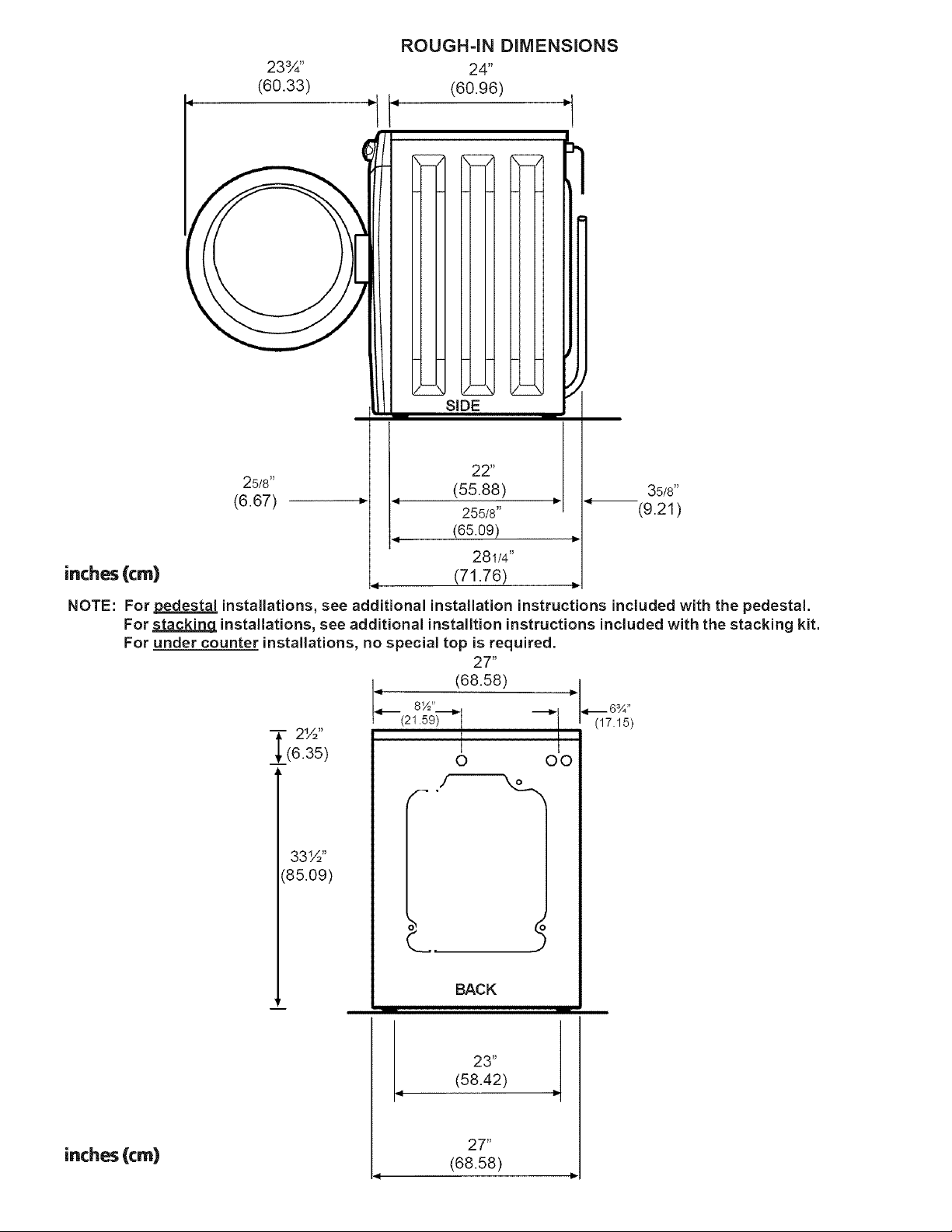
23¾"
(60.33)
ROUGH-iN DiMENSiONS
24"
(60.96)
_ - siDE
inches(cm)
NOTE:
For pedestal installations, see additional installation instructions included with the pedestal.
For stacking installations, see additional installtion instructions included with the stacking kit.
For under counter installations, no special top is required.
25/8"
(6.67)
" 1 (68.58)
_- 2½" (17.15)
____(6.35) 0 O0
22" ,
(55.88)
255/8"
(65.09)
281/4"
(71.76)
27"
_ ./-----_
33½"
:85.09)
35/8"
_(9.21 )
inches(¢m)
BACK
i -- w
4 23"
9
(58.42)
27"
(68.58)
LOCATION OF YOUR WASHER
DO NOT INSTALL YOUR WASHER:
I. Inan area exposed to dripping water or outside weather conditions. The ambient temperature should never be below 60 ° F
(15.6 ° C) for proper washer (detergent breakdown) operation.
2. In an area where it will come in contact with curtains or drapes.
3. In an area (garage or garage-type building) where gasoline of other flammables are kept or stored (including automobiles).
4. On carpet. Floor MUST be solid with a maximum slope of 1/2 in. per foot (1.27 cm per 30.5 cm). To ensure vibration or
movement does not occur, reinforcement of the floor may be necessary.
IMPORTANT
MINIMUM INSTALLATION CLEARANCES
When installed in alcove or closet:
Sides, Rear = 0 in. (0 cm)
Top = 0 in. (0 cm)
When installed in closet: Front = I in. (2.54 cm)
Closet door ventilation required: 2 Iouvered openings each 60 in2(387 cm2), 3 in. (7.6 cm) from top and bottom of door.
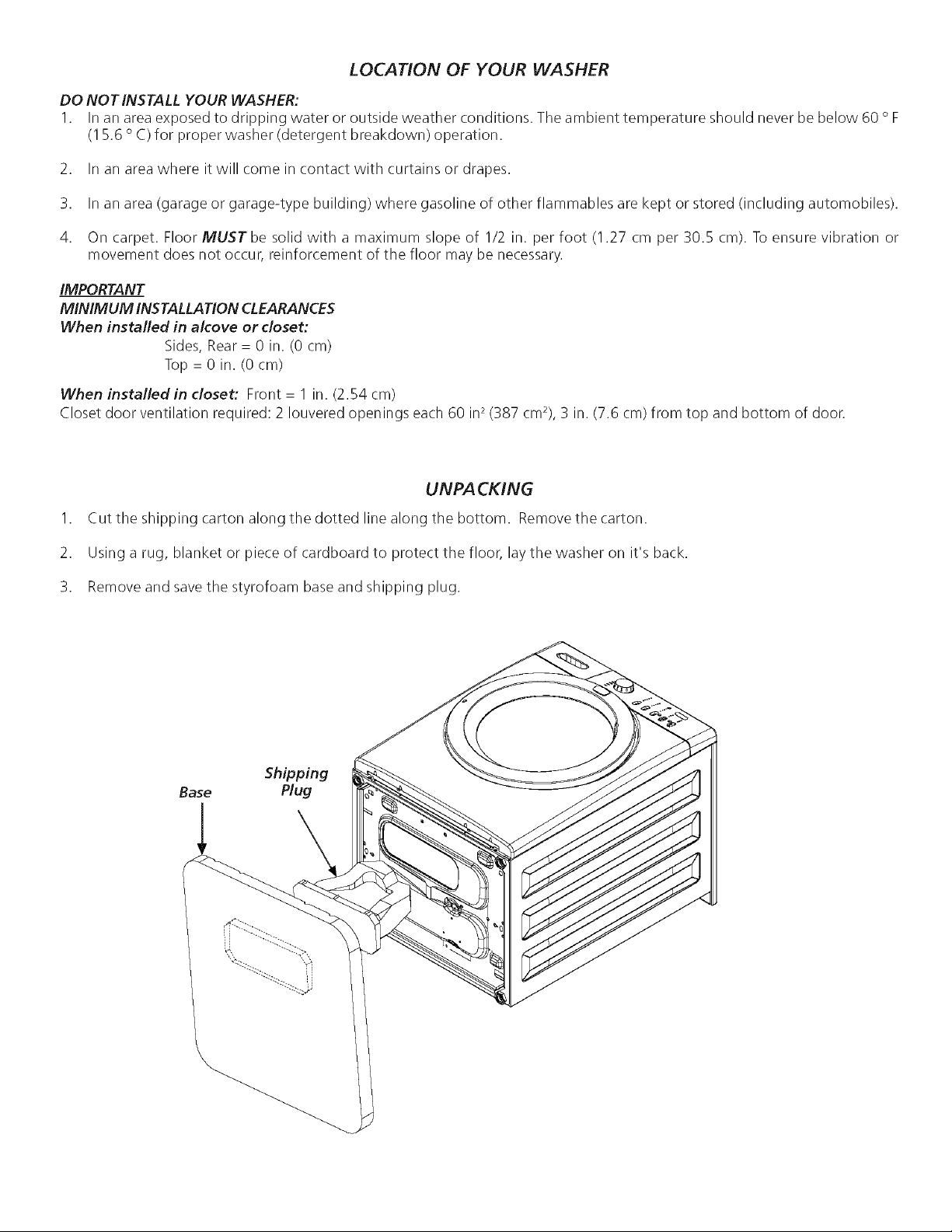
UNPACKING
1. Cut the shipping carton along the dotted line along the bottom. Removethe carton.
2. Using a rug, blanket or piece of cardboard to protect the floor, laythe washer on it's back.
3. Remove and savethe styrofoam base and shipping plug.
Shipping
Base Plug
 Loading...