

Page 1
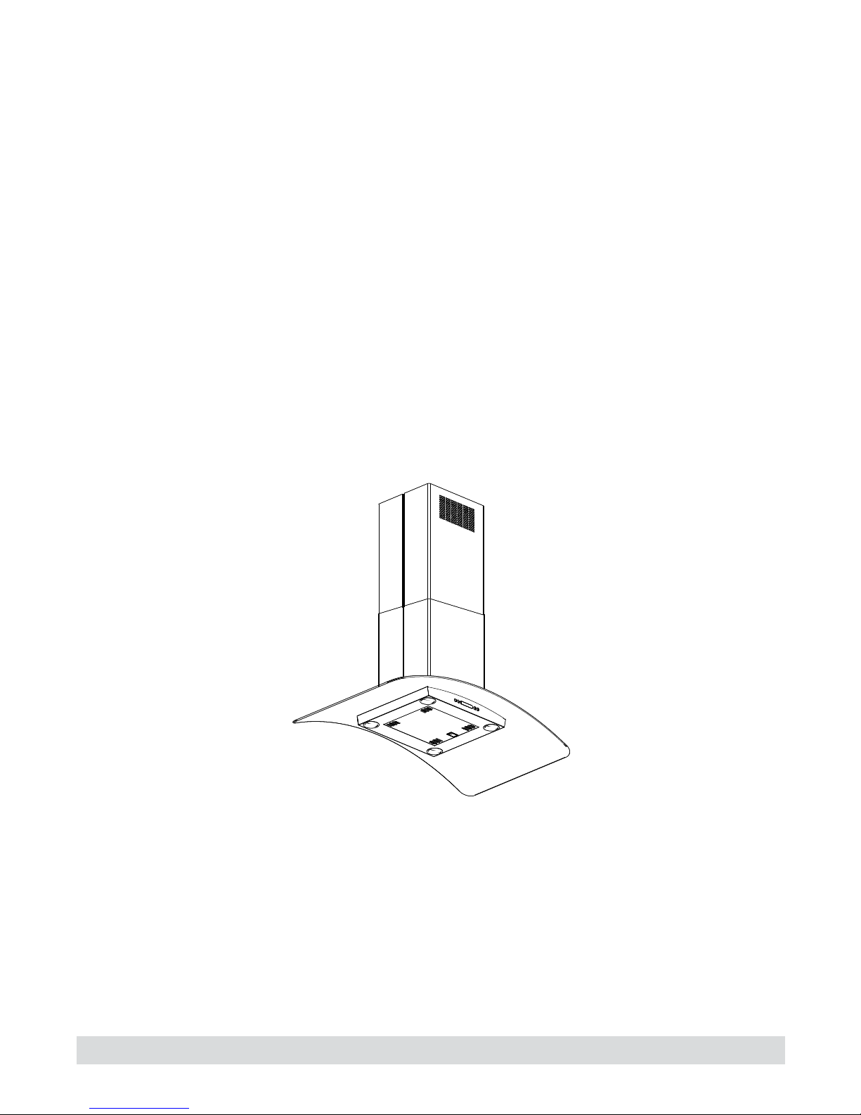
Installation, Use & Care Guide
36” and 42” Island Range Hood
Guia de Instalación, Uso y Cuidado
36” y 42” Campana extractora
Guide d’installation, utilisation et
d’entretien
36” et 42” Hotte aspirante
RH36PC60GSB + RH42PC60GSB 316495104
AUG/12
Page 2
2
Finding Information
Please read and save this guide
Thank you for choosing ElectElectrolux, the new premium brand in home appliances. This Use Í Care Guide is
part of our commitment to customer satisfaction and product quality throughout the service life of your new
appliance.
We view your purchase as the beginning of a relationship. To ensure our ability to continue serving you,
please use this page to record important product information.
Keep a record for quick reference
Purchase date
Model number
Serial number (see picture for location)
NOTE
Registering your product with Electrolux enhances
our ability to serve you. You can register online at
www.electroluxappliances.com by dropping your
Product Registration Card in the mail.
Questions?
For toll-free telephone support in the U.S. and Canada:
(1-877-435-3287)
For online support and Internet product information visit http:// www.electroluxappliances.com
Table of contents
Important Safety Instructions ............................. 3-4
Electrical Í Installation requirements ..................... 5
Electrical requirements ............................................... 5
IMPOTANT.................................................................... 5
Before installing the hood ............................................5
.Parts Included with your hood .................................. 6
Optional Accessories ..................................................
Tools/Materials required .............................................. 6
Installing the hood ................................................. 7-9
Installing preparation................................................... 8
Removing the packaging ........................................... 8
Ceiling Support Structures ......................................... 9
Ceiling ducting............................................................10
Making the electrical connections ............................12
Connecting the ductwork ......................................... 13
Air deector installation
(Recirculating accessories) .......................................13
Features .......................................................................14
Control buttons ...........................................................15
Special functions ........................................................16
Clock programming .....................................................16
Grease lter saturation alarm.......................................16
Charcoal lter saturation alarm
6
(Recirculating accessories) ..........................................16
Audible signal activation and deactivation .................16
Charcoal lter inclusion and exclusion
(Recirculating accessories)..........................................16
Heat sensor...................................................................16
For Best results ............................................................ 17
Care and cleaning ......................................................18
Filters .............................................................................18
Lights ............................................................................18
Optional Charcoal Filters .............................................19
Hood Surface ...............................................................19
Warranty Information ................................................ 20
©2007 Electrolux Home Products, Inc. All rights reserved. Printed in Mexico
Page 3
Important Safety Instructions
Read all instructions before using this
appliance.
Save these instructions for future e
rerference
Approved for residential appliances
For residential use only
Do not attempt to install or operate your appliance
until you have read the safety precautions in this
manual. Safety items throughout this manual are
labeled with a WARNING or CAUTION based on the
risk type.
This symbol alerts you to
situations that may cause
serious body harm, death
or property damage.
Important Safety Instructions
3
This symbol alerts you to
situations that may cause
bodily injury or property
damage.
PLEASE READ ENTIRE INSTRUCTIONS BEFORE PROCEEDING.
INSTALLATION MUST COMPLY WITH ALL LOCAL CODES.
IMPORTANT: Save these Instructions for the Local Electrical Inspector’s use.
INSTALLER: Please leave these Instructions with this unit for the owner.
OWNER: Please retain these instructions for future reference.
Safety Warning: Turn off power circuit at service panel and lock out panel, before wiring this appliance.
Requirement: 120 V AC, 60 Hz. 15 or 20 A Branch Circuit
Page 4
4
Important safety Instructions
READ AND SAVE THESE INSTRUCTIONS
Important safety Instructions
FOR GENERAL VENTILATING USE ONLY. DO NOT USE
TO EXHAUST HAZARDOUS OR EXPLOSIVE MATERIALS OR VAPORS.
TO REDUCE THE RISK OF FIRE, ELECTRIC SHOCK,
OR INJURY TO PERSONS, OBSERVE THE FOL-
LOWING:
Use this unit only in the manner intended by the
A.
manufacturer. If you have questions, contact the
manufacturer
Before servicing or cleaning the unit, switch power off
B.
at service panel and lock service panel disconnecting
means to prevent power from being switched on
accidentally. When the service disconnecting means
cannot be locked, securely fasten a prominent warning
device, such as a tag, to the service panel.
Installation Work and Electrical Wiring Must Be Done By
C.
Qualied Person(s) In Accordance With all Aplicable
Codes & Standards, Including Fire-rated Construction.
Sufcient air is needed for proper combustion and ex
D.
hausting of gases through the ue (Chimney) of fuel
burning equipment to prevent back- drafting. Follow
the heating equipment manufacturers guideline
and safety standards such as those published by
the National Fire Protection Association (NFPA),
the American Society for Heating, Refrigeration and Air
Conditioning Engineers (ASHRAE), and the local code
authorities.
When cutting or drilling into wall or ceiling, do not dam
E.
age electrical wiring and other hidden utilities.
Ducted systems must always be vented to the
F.
outdoors.
To reduce risk of re and to properly exhaust air, be sure to
duct air outside - do not vent exhaust air into spaces within
walls, ceilings, attics, crawl spaces, or garages.
TO REDUCE THE RISK OF FIRE, USE ONLY METAL
DUCT WORK.
Install this hood in accordance with all requirements
specied.
To Reduce The Risk Of Fire Or Electric Shock, Do Not
Use This Hood With Any External Solid State Speed
Control Device.
Automatically Operated Device - To Reduce The
Risk Of Injury Disconnect From Power Supply Before
Servicing.
This unit is equpeed with integral disconnecting switch
located inside the blower housing.
TO REDUCE THE RISK OF A RANGE TOP GREASE
FIRE.
Never leave surface units unattended at high settings.
a)
Boilovers cause smoking and greasy spillovers that
may ignite. Heat oils slowly on low or medium settings.
Always turn hood ON when cooking at high heat or
b)
when ambeing food (l.e. Crepes Suzette, Cherries
Jubilee, Peppercorn Beef Flambe’).
Clean ventilating fans frequently. Grease should not
c)
be allowed to accumulate on fan or lter.
Use proper pan size. Always use cookware appropriate
d)
for the size of the surface element.
TO REDUCE THE RISK OF INJURY TO PERSONS, IN
THE EVENT OF A RANGE TOP GREASE FIRE,
OBSERVE THE FOLLOWING:
SMOTHER FLAMES with a close - tting lid, cookie
a)
sheet, or other metal tray, then turn off the gas burner
or the electric element. BE CAREFUL TO PREVENT
BURNS. If the ames do not go out immediately,
EVACUATE AND CALL THE FIRE DEPARTMENT.
NEVER PICK UP A FLAMING PAN - you may be
b)
burned.
DO NOT USE WATER, including wet dishcloths or
c)
towels - a violent steam explosion will result.
Use an extinguisher ONLY if:
d)
You know you have a class ABC extinguisher,
1)
and you already know how to operate it.
The re is small and contained in the area
2)
where it started.
The re department is being called.
3)
You can ght the re with your back to an exit.
4)
OPERATION
a. Always leave safety grills and lters in place.Without
these components, operating blowers could catch onto hair,
ngers and loose clothing.
The manufacturer declines all responsibility in the event
of failure to observe the instructions given here for
installation,maintenance and suitable use of the product.
The manufacturer further declines all responsibility for injury
due to negligence and the warranty of the unit automatically
expires due to improper maintenance.
Page 5
Important safety Instructions - Electrical & Installation
READ AND SAVE THESE INSTRUCTIONS
Electrical & Installation requirements
requirements
5
Electrical requirements
IMPORTANT
Observe all governing codes and ordinances.
It is the customer’s responsibility:
To contact a quali!ed electrical installer.
To assure that the electrical installation is adequate
and in conformance with National Electrical Code,
ANSI/NFPA 70 — latest edition*, or CSA Standards
C22.1-94, Canadian Electrical Code, Part 1 and
C22.2 No.0-M91 - latest edition** and all local codes
and ordinances.
If codes permit and a separate ground wire is used, it
is recommended that a quali!ed electrician determine
that the ground path is adequate.
Do not ground to a gas pipe.
Check with a quali!ed electrician if you are not sure
range hood is properly grounded.
Do not have a fuse in the neutral or ground circuit.
IMPORTANT
Save Installation Instructions for electrical inspector’s
use.
The range hood must be connected with copper wire
only.
The range hood should be connected directly to the
fused disconnect (Or circuit breaker) box through
metal electrical conduit.
Wire sizes must conform to the requirements of the
National Electrical Code ANSI/NFPA 70 — latest edition*,or CSA Standards C22.1-94, Canadian
Electrical Code Part 1 and C22.2 No. 0-M91 - latest
edition**and all local codes and ordinances.
Before installing the hood
For the most effcient air ow exhaust, use a
1.
straight run or as few elbows as possible.
Vent unit to outside of building and recirculating.
At least two people are necessary for installation.
2.
The hood is tted with Screws and Drywall
3.
Anchors suitable for most surfaces, consult a
Qualied Installer, check if they perfectly t with
your cabinet/wall.
Do not use flex ducting.
4.
COLD WEATHER installations should have an
5.
additional backdraft damper that is already
installed to minimize backward cold air ow and a
nonmetallic thermal break to minimize
conduction of outside temperatures as part
of the ductwork. The damper should be
on the cold air side of the thermal break.
The break should be as close as possible
to where the ducting enters the heated portion
of the house.
Make up air: Local building codes may require the
6.
use of Make-Up Air Systems when using Ducted
Ventilation Systems greater than specied CFM of
air movement.
The specied CFM varies from locale to locale.
Consult your HVAC professional for specic
requirements in your area.
A U.L.- or C.S.A.-listed conduit connector must be
provided at each end of the power supply conduit (at
the range hood and at the junction box).
Copies of the standards listed may be obtained from:
* National Fire Protection Association Batterymarch Park
Quincy,Massachusetts 02269
** CSA International 8501 East Pleasant Valley Road Cleveland, Ohio
44131-5575
Page 6
6
List of Materials
List of Materials
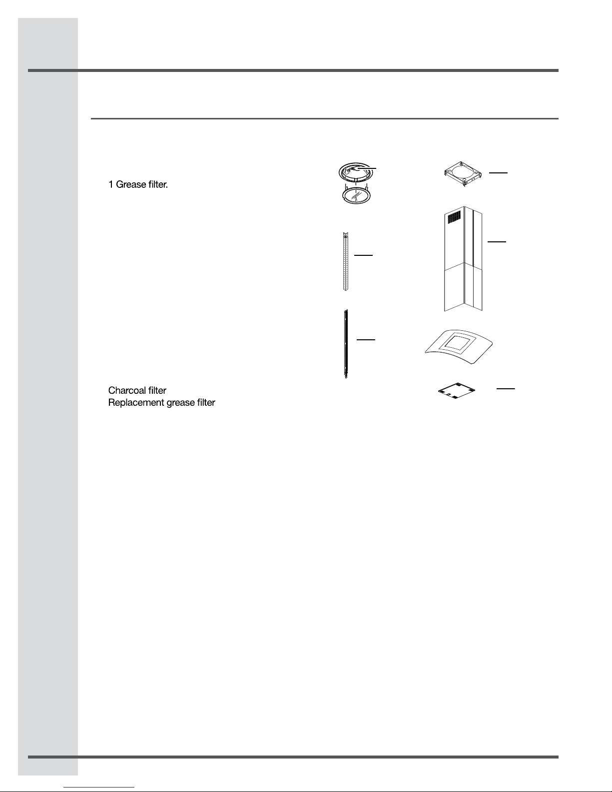
Parts included in your hood
Hood structure assembly with blower, transition.
•
4 Lamps already installed.
•
•
4 Duct covers.
•
2 Bottom.
•
2 Top.
•
Hardware bag with:
•
Ceiling Mount Template
•
Use, care and installation guide
•
Wood screws (4 pieces - 3/16” x 1” 3/4)
•
Assembly screws (74 pieces)
•
4 Plastic Springs to attach duct covers
•
8 Vertical supports.
•
2 Upper Ductcover supports.
•
2 Horizontal supports.
•
Lamp
Vertical
supports
Duct cover
support
Upper
Duct cover
supports
Duct
Covers
Optional accessories
Recirculation KIT
•
•
•
Tools/Materials required
Aluminum tape
•
Wire nuts
•
Tape to mount template
•
1/2” electrical connector (junction box)•
8” rounded metal duct (length to suit installation)
•
Measuring tape
•
Pliers
•
Gloves to protect against sharp edges
•
Knife
•
Safety glasses
•
Electric drill with 5/16” and 3/8” bits
•
Strain relief 1/2” conduit connector
•
Level
•
Phillips (Pozidrive) # 2 screwdriver + torx # 2
•
Wire cutter/stripper
•
Masking tape
•
Hammer
•
Saw, jigsaw or reciprocating saw
•
Grease
Filter
Page 7
Installing the hood
For the most ecient air ow exhaust, use a
•
straight run or as few elbows as possible.
Vent unit to outside of building and recirculating.
On avarage 2 to 3 hours are necessary to com-
•
plete installation (without considering cut to be
done on wall and or on cabinet, installation of
ducts , conduit and electrical connections to the
mains).
The hood is tted with Screws and Drywall
•
Anchors suitable for most surfaces, consult a
Qualied Installer, check if they perfectly t with
your cabinet/wall.
Installing the hood
Typical installation
•
Min installation height from the range top to the
bottom of the hood is 30” if a gas range is used
or 24” to 30” if an electric range is used.
These hoods are not recommended to be used
over indoor grills.
The hood may be installed vented to the outdoors, or
it can be installed for recirculating operation
(recirculating accessories not supplied with the
hood).
This hood can be installed over any electric and
gas cooktop/range.
This hood must not be installed over any
professional cooktop / range.
7
Do not use ex ducting.
•
COLD WEATHER installations should have an
•
additional backdraft damper that is already in
stalled backward cold air ow and a nonmetallic
thermal to minimize break to minimize conduction
of outside temperatures as part of the ductwork.
The damper should be on the cold air side of the
thermal break.
The break should be as close as possible to
where the ducting enters the heated portion of
the house.
Make up air: Local building codes may require
•
the use of Make-Up Air Systems when using
Ducted Ventilation Systems greater than specied
CFM of air movement.
The specied CFM varies from locale to locale.
Consult your HVAC professional for specic
requirements in your area.
Page 8
8
Installing the hood
Installing preparation
The vent hood should be on site before nal
•
framing and wall nishing. This will help to
accurately locate the duct work and electrical
service.
Installation will be easier if the vent hood is
•
installed before the cook-top and countertop are
installed.
Ductwork and wiring locations:
Determine the exact location of the vent hood.
•
Plan the route for venting exhaust to the
•
outdoors.
Use the shortest and straightest duct route
•
possible.
For satisfactory performance duct run should not
exceed 100’ equivalent length for any duct
congurations.
Refer to “Ductwork installation guidelines” chart
•
to compute the maximum permissible length fo r
duct runs to the outdoors.
Ductwork installation guidelines
For safety reasons, ducting should vent directly
outdoors (not into an attic, underneath the house,
into the garage or into any enclosed space).
Keep duct runs as short and straight as possible.
Duct ttings (elbows and transitions) reduce air
ow eciency.
Back to back elbows and “S“ turns give very poor
delivery and are not recommended.
A short straight length of duct at the inlet of the
remote blower gives the best delivery.
Transition to duct from the integral blower or
remote duct transition as close to the downdraft
as is possible.
In order of preference, use
1st. 10” round duct
2nd. 8” round duct
3rd. 3-1/4” x 14” duct
4th. 7” round duct
5th. 3-1/4” x l0” duct
6th. 6” round duct
Removing the packaging
Remove the carton carefully. Wear gloves to protect
against sharp edges.
Remove the protective !lm covering the product
before putting into operation.
The use of exible metal round duct should only
be used when no other duct tting exists. Limit
use to short lengths and do not crush when
making corners.
Install a wall cap with damper or roof cap at the
•
exterior opening. Order the wall or roof cap and
any transition needed in advance.
Use 8” round metal ductwork only.
•
Page 9
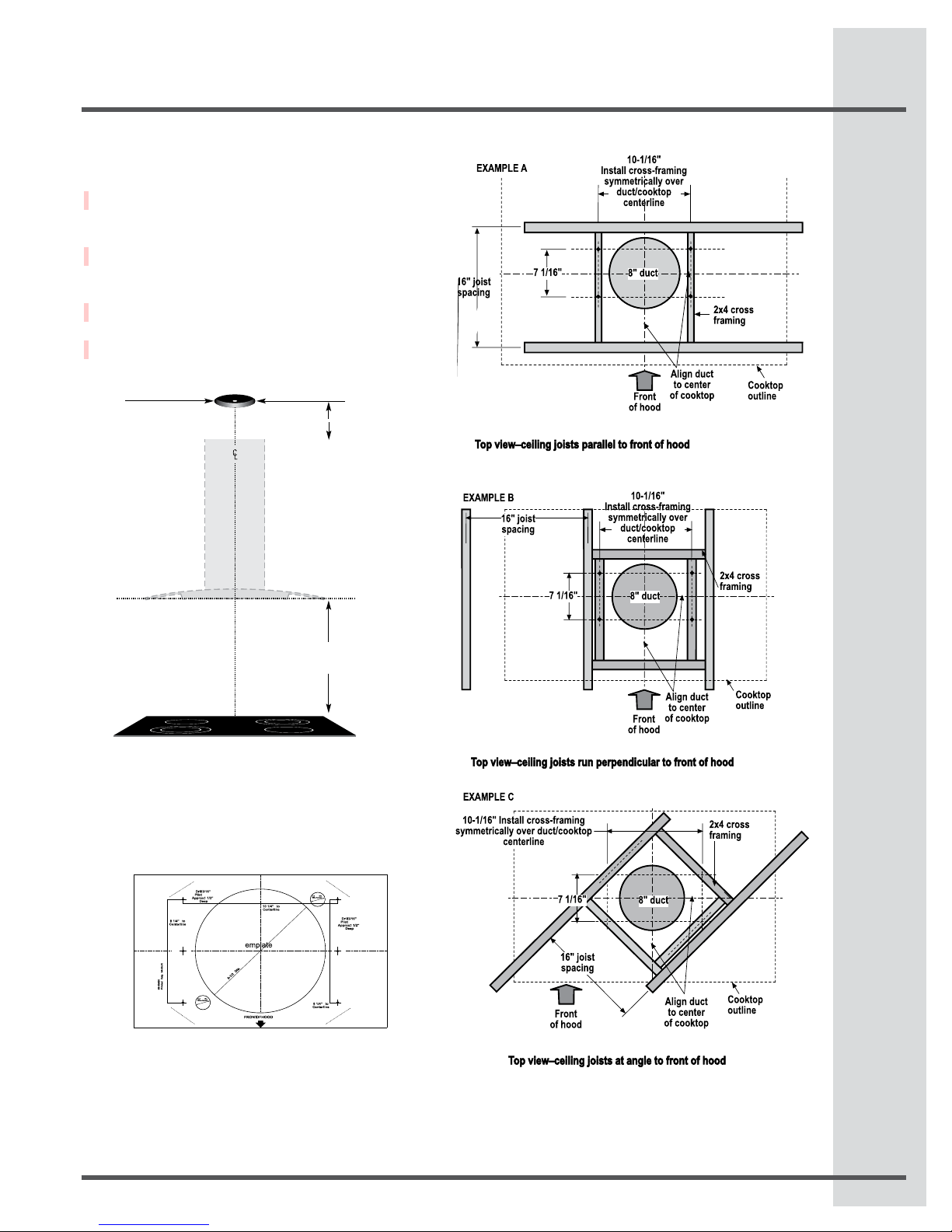
Ceiling Support Structures
This vent hood is heavy.
•
Adequate structure and support must be
provided in all types of installations.
At the hood location, install 2”x 4” cross framing
•
between ceiling joists as shown. (2”x 4” are
required to support the weight of the hood.)
Arrange cross framing in the ceiling to suit the
•
existing structure.
Your ceiling joists will be like one of the following
•
examples.
81/2“
12
4
/16“ (At least)
Installing the hood
9
8’ Ceiling: 24” (minimum)
9’ Ceiling: 30” (minimum)
NOTE: Do not cut the duct opening shown on
the template for the recirculating installation.
IMPOR TANT
Framing must be capable of supporting 150lbs.
Page 10
10
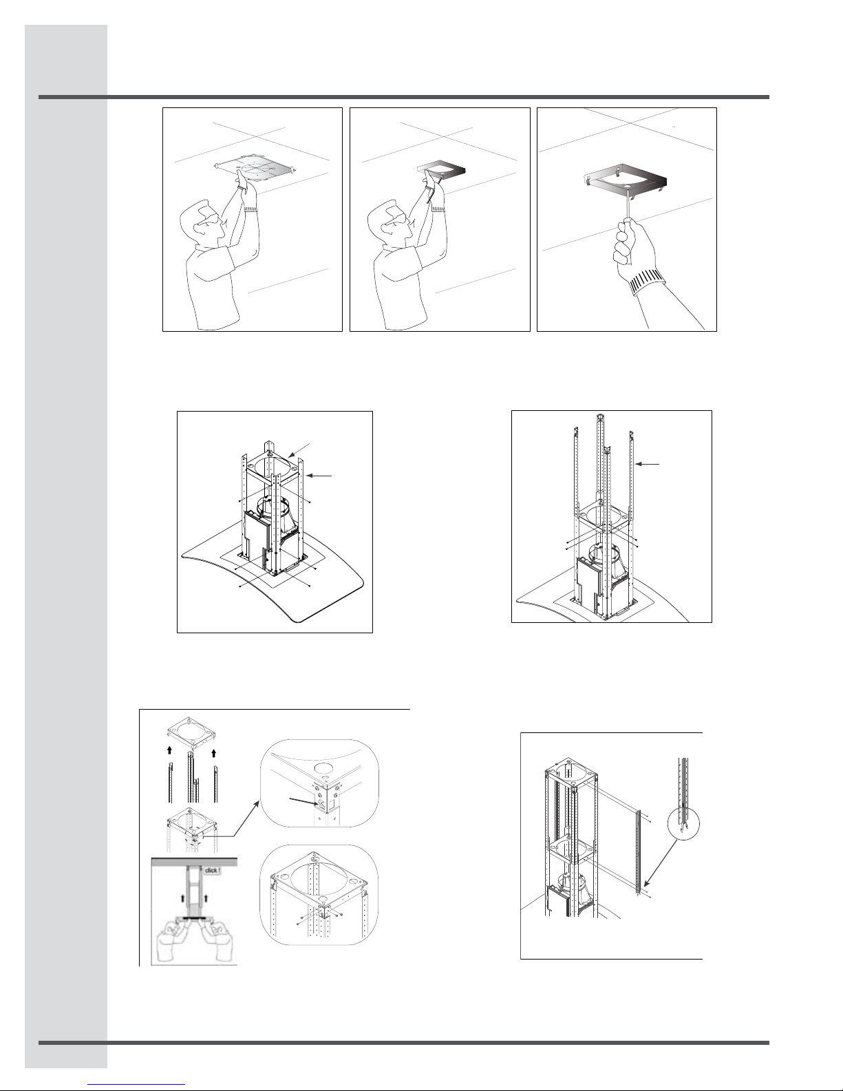
click!
Installing the hood
Place the template on to ceiling considering
the instructions for ceiling support
structures. Always consider the “front of
hood” legend when placing the template
on the ceiling. It will dene the control’s
location.
Mark with a pencil the hole locations for
screws in the ceiling.
Remove template.
B
A
Place the hood over a table protecting the glass Attach the
4 lower vertical supports (A) to the hood with 16 assembly
screws (4 per corner). Then attach the lower horizontal support
(B) with 8 assembly screws (2 per corner).
Secure the upper horizontal support with
4 wood screws.
C
The upper vertical supports’ position will determine the hood’s total height.
Refer to the maximum and minimum extensions line drawing to determine
which is the most suitable dimension according to your ceiling’s height.
Always take into consideration the minimum installation heights declared in
this manual. Position the upper vertical supports (C) at the proper height and
attach them with 16 assembly screws (4 per corner).
Carefully lift the assembly until the upper vertical supports are locked
with the 4 upper horizontal support’s springs. Secure with 16 assembly
screws (4 per corner).
Note: At least 2 persons are needed for this operation.
Attach the stainless steel duct cover
supports using 4 assembly screws.
Page 11
A1
A
B
A
Installing the hood
11
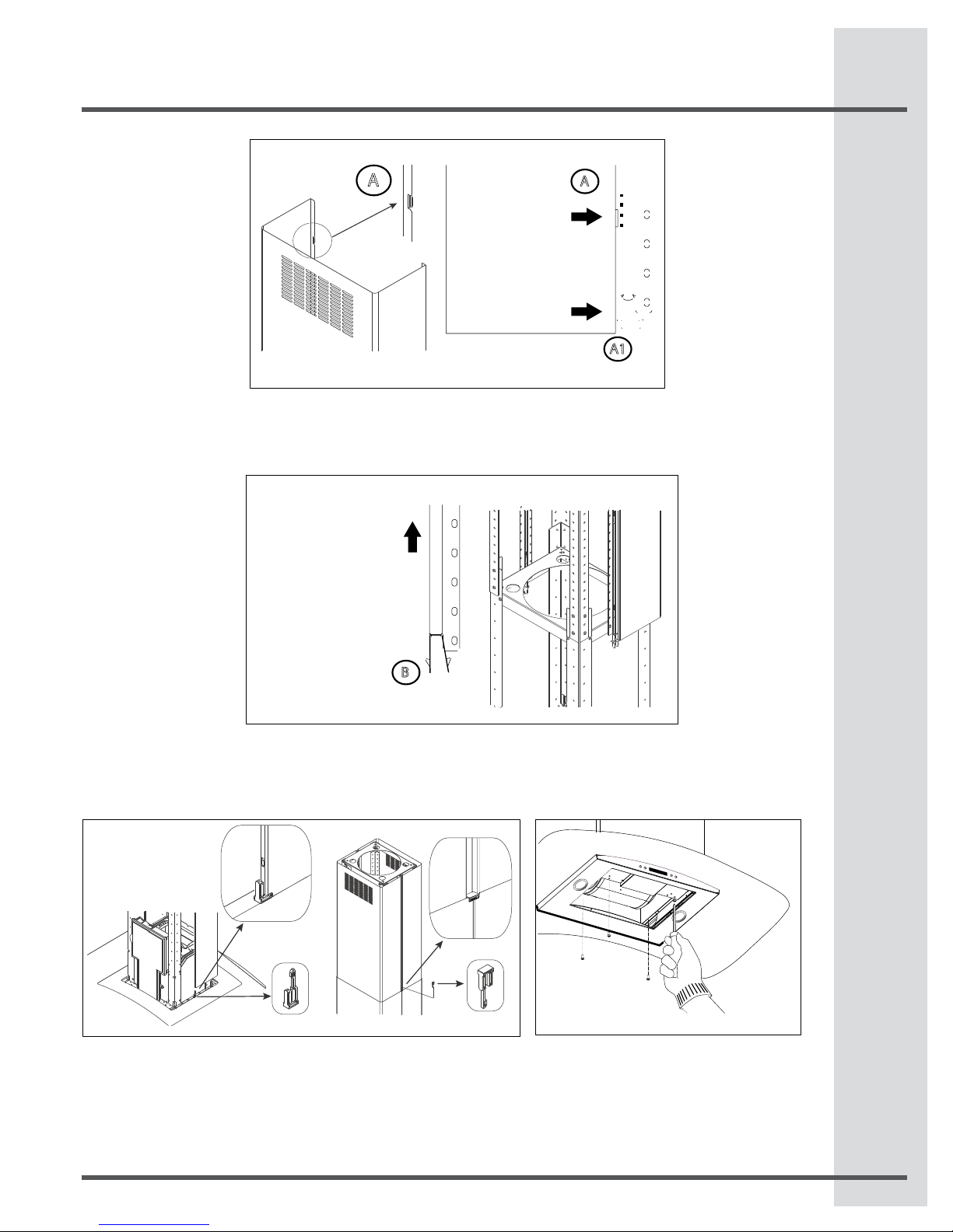
To place the upper duct covers, make sure that the duct cover’s tabs are aligned
and inserted into the stainless steel duct cover support’s slots as shown in image
“A”. While aligning and inserting the tabs, the lower part of the duct cover must
be pushing the metal spring inside at all times as shown in “A1”. Keep the duct cover
in this position.
To lock the upper duct cover in place, slide it upwards making sure that all tabs stay
inside the respective slots. When sliding the duct cover upwards, make sure that the
lower part of the duct cover is locked with the metal spring as shown in “B”. A click
sound will be heard. Note: 2 persons are needed for this operation.
Place lower duct covers using one plastic bracket at each vertex ( 4 needed). The lower duct cover must be secured to the ranger
hood with 4 assembly screws.
Page 12
12
Metal electrical
conduit
House
wiring
UL listed
wire nut
Installing the hood
Ceiling ducting
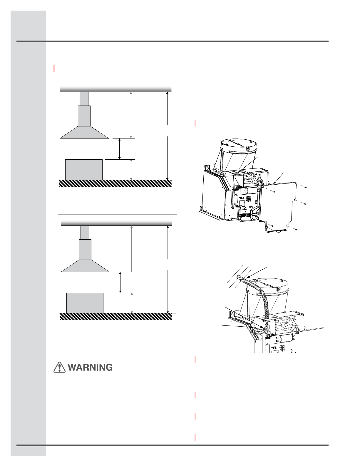
Use the template previously installed to prepare a
•
8 - ½” hole in the ceiling for ductwork.
50” max
extension
10’ = 120”
Ceiling Height
35”
(Minimum
Installation Height)
RANGE
When the Island is installed in a 10’ Ceiling,
35” is the closest distance we can have from
the cooking surface. 35” is the recommended height
36”
TO PROTECT YOU AGAINST ELECTRIC SHOCK,
THE GREEN AND YELLOW WIRE MUST BE
CONNECTED TO THE GROUNDING WIRE IN
YOUR HOME ELECTRICAL SYSTEM, AND IT MUST
UNDER NO CIRCUMSTANCES BE CUT OR
REMOVED.
Failure to do so can result in death
or electrical shock.
Remove junction box cover and knockout on the
•
top left side.
Knockout
Junction box
cover
30” min
extension
8’ = 96”
Ceiling Height
30”
(Maximum
Installation Height)
RANGE
36”
When the Island is installed in an 8’ Ceiling, 30” is
the longest distance we can have from the cooking
surface. 30” is the recommended height 24” - 30” for
electrical cooking surface
Making the electrical connections
Electrical Shock Hazard
Warning: turn off power at the service panel before
wiring this unit.
120 V AC, 15 or 20 Amp circuit required.
ELECTRICAL GROUNDING INSTRUCTIONS
THIS APPLIANCE IS FITTED WITH AN ELECTRICAL
JUNCTION BOX WITH 3 WIRES, ONE OF WHICH
(GREEN/YELLOW) SERVES TO GROUND THE
APPLIANCE.
•
If not already done, install 1/2” conduit connector
in j- box.
NOTE: This connector is not included with vent hood.
•
Run black (live), white (neutral), and green (earth)
wires (# 14 AWG) according to the National
Electrical Code or CSA Standards and local
codes and ordinances in 1/2” conduit from power
supply to j- box.
•
Connect black, white, and green wires from
power supply to black, white, and green/yellow
wires in j - box respectively.
•
These connections should be done always
making reference to the electrical diagram found
inside the hood.
Close j - box cover and reapply screws.
•
Page 13
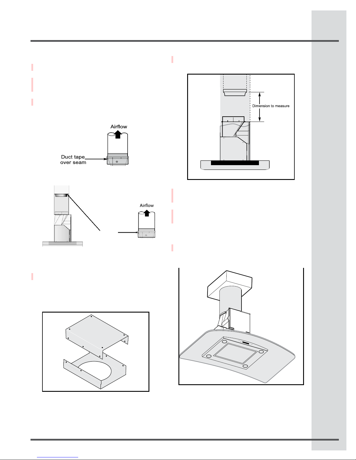
Connecting the ductwork
Install ductwork, making connections in the
•
direction of airow as illustrated.
Push duct over the exhaust outlet.
•
Wrap all duct joints and the ange connections
•
with duct tape for an airtight seal.
Make the same connection in the wall or ceiling
•
vent exit.
Ductwork
Duct tape
over seams
Hood
Air deect installation
(Recirculating accessories)
Assemble the air deector with the duct cover
•
bracket with 4 assembly screws provided as
shown.
Installing the hood
Measure from the bottom of the air deector to
•
the bottom of the hood outlet, as shown.
Cut the duct at the measured size.
•
Uninstall the air deector removing the 4
•
assembly screws.
Slip the duct onto the bottom of the deector.
•
Place the assembled deector and duct over the
•
exhaust outlet from the hood. Assemble the air
deector with the duct cover bracket with 4
assembly screws provided as shown.
Use duct tape to seal the deector and at the
•
exhaust outlet from the hood.
13
Page 14
14
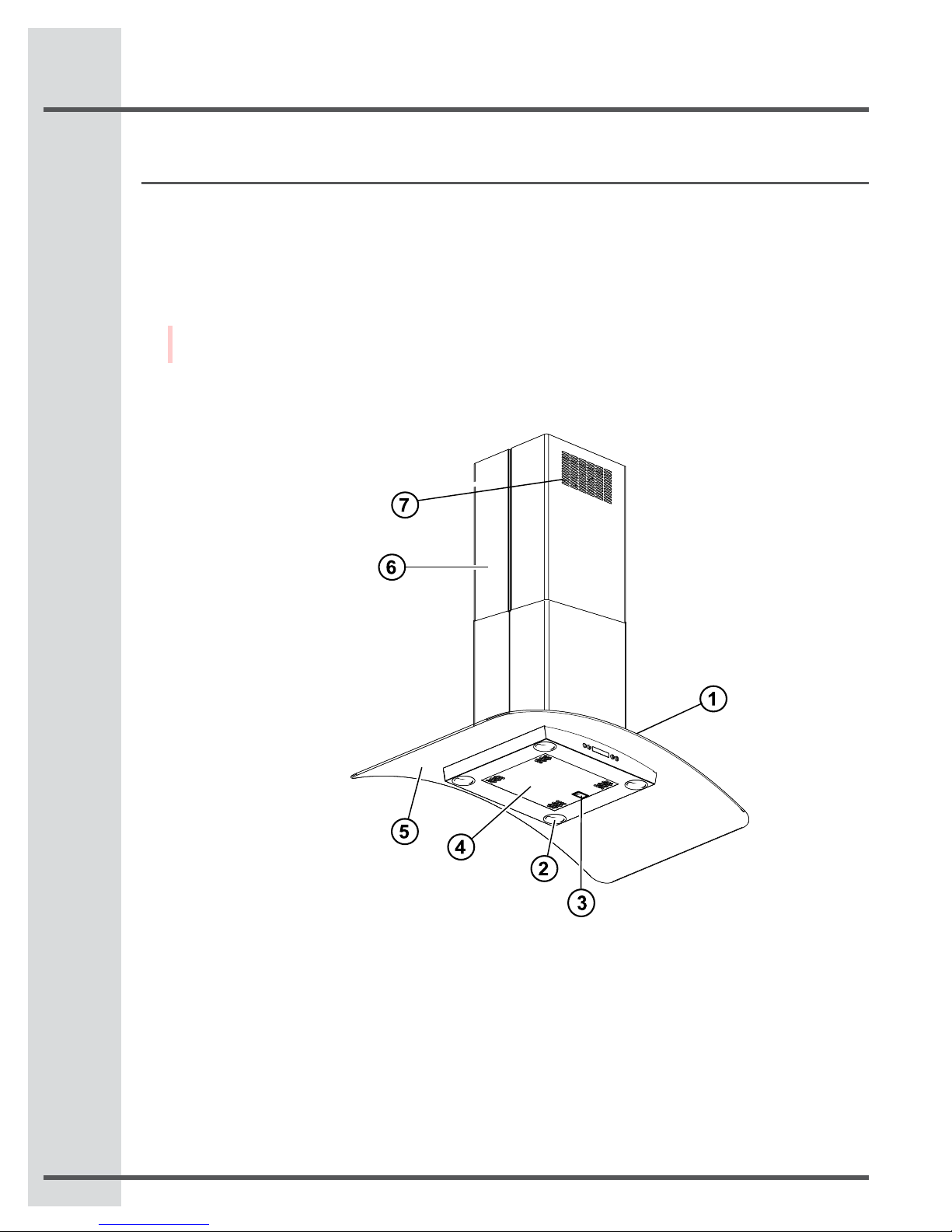
Features
Features
Blower and light controls
1.
Lamp housings
2.
Grease lter Handle
3.
Grease lter
4.
Canopy
5.
Duct covers
6.
Bottom
•
Top
•
Louver holes (Only for Recirculating version)
7.
Page 15
Control buttons
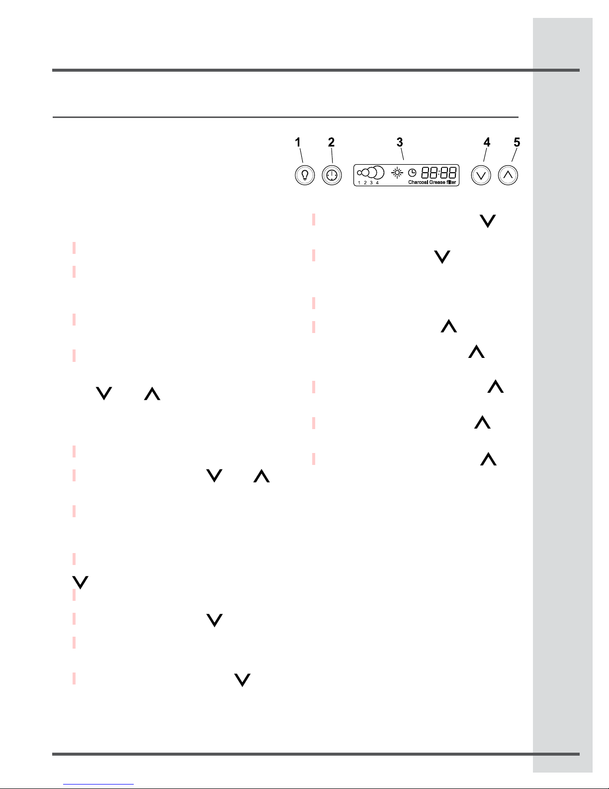
This hood is equipped with an electronic motor and
lamp control.
The control is able to set 4 different fan speeds, turn
ON/OFF light and has a timer function.
In the following drawing are described the main key
functions.
1. Light Button
Press lamp button to turn ON the light (Lamp
•
state previously OFF).
Press lamp button to turn OFF the light (Lamp
•
state previously ON).
2. Timer Button
The default timer setting is 10 minutes, and it
•
can be adjusted between 20 minutes and
1minute.
After pressing the timer button, the control
•
enters to a timer setup mode, and user can
adjust the timer countdown time with the
“ ” and “ ” buttons within 5 seconds.
The timer can be initiated immediately
pressing the timer button, after setting the
timer duration or pressing the timer button
twice (default 10 minutes setting).
If no action occurs within 5 seconds, the
•
countdown will start.
During the timer setup the “ ” and “ ”
•
buttons are dedicated to the timer and no
motor action will occur.
Once the timer is initiated, it can be cancelled
•
by pressing the timer button again.
Control buttons
If the fan is at fourth speed and the “ ”
•
button is pressed, the fan will be set to third
speed.
If the fan is OFF and the “ ” button is
•
pressed, the control backlight will light up.
5. “ ” Button. Speed Increase / ON
This button is used to increase the fan speed,
•
or turn ON the fan.
The fan will turn ON if the “ ” button is
•
pressed and the hood was OFF.
If the fan is at rst speed and the“ ” button
is pressed, the fan will be set to second
speed.
If the fan is at second speed and the “ ”
•
button is pressed, the fan will be set to third
speed.
If the fan is at third speed and the “ ”
•
button is pressed, the fan will be set to fourth
speed.
If the fan is at fourth speed and the “ ”
•
button is pressed, a beep will sound.
15
3. Display
Shows the hood settings.
•
4. “ ” Button. Speed Decrease / OFF
This button is used to decrease the fan
•
speed, or turn OFF the fan.
The fan will turn OFF if the “ ” button is
•
pressed and the hood was in the rst speed.
If the fan is at second speed and the “ ”
•
buttom is pressed, the fan will be set to rst
speed.
If the fan is at third speed and the “ ”
•
key is pressed, the fan will be set to second
speed.
Page 16
16
16
Control buttons - Special functions
Special functions
Clock programming
The clock can be reprogrammed at any time except during an active timed function.
•
The clock can be displayed in a twelve hour format and valid clock times are from 1:00 to 12:59.
•
The clock can be reprogrammed pressing the “ Timer” button for 5 seconds, and after, the clock can be
•
adjusted with the “ ” and “ ” buttons. Colon “:” with ash indicating clocks programming mode.
The user can have minute increments / decrements of 1 minute, but if the user keep pressing the “ ”/
•
” ” buttons for more than 1 second, the increments / decrements will be of 5 minutes.
During this option the control will round to the nearest 5 minutes.
The user can nish on reprogramming the clock pressing the “Timer” button.
•
After 1 minute of no button pressed the control will accept the programmed clock time and will add one
•
minute to the set clock.
Grease lter saturation alarm
After thirty fan functional hours, the display will show “Grease Filter” if the fan is active.
•
When this icon is shown in the display, the grease lters installed are required to be washed.
To reset the grease lter saturation alarm the user must press the “ ” button for 5 seconds, after this
•
action the icon
“Grease filter” is not displayed, and the hood has the normal display operation.
Charcoal lter saturation alarm (Recirculating accessories)
After one hundred and twenty functional hours of the fan, the display will show “Charcoal Filter” if the fan
•
is active. When this icon ashes on display, the charcoal lters installed are required to be replaced or
reactivated.
To reset the charcoal lter saturation indication the user must press the “ ” button for 5 seconds, after
•
this time the icon
“Charcoal filter” is not displayed and the hood has the normal display operation.
Audible signal activation and deactivation
The audible signals can be activated or deactivated pressing the “Light” button for 5 seconds.
•
If the audible signal is activated, a tone must sound and the “Snd” symbol must appear on the display for
•
2 seconds.
If the audible signal is deactivated, the “Snd” symbol must appear on the display for 2 seconds and no
•
tone must sound.
Charcoal lter inclusion and exclusion (Recirculating accessories)
The charcoal lter inclusion or exclusion can be set by pressing the “ ” and “ ” buttons at the same
•
time for 5 seconds.
The inclusion or exclusion of charcoal lter must be selected while the lamps and the motor are OFF.
•
When the charcoal lter has been excluded, the charcoal lter alarm is disabled.
•
Heat sensor
The control is equipped with a heat sensor that will turn on the blower at second speed if excessive heat
•
occurs (over 158° F or 70°C) surrounding the control area.
If the blower is OFF or if it is operating at rst speed, the blower will be set automatically to second speed,
•
the display shows the word “CArE” to indicate that heat sensor has detected an excessive heat.
During this state, the user may raise the blower speed to third speed but can not decrease the speed.
•
When the temperature level on the hood drops to normal, the blower will operate in the setting dened by
•
the user before the alarm occured.
Page 17

Control buttons
For Best results
Continuous use of the fan system while cooking helps keep the kitchen comfortable and less humid.
•
It also reduces cooking odors and soiling moisture that create a frequent need for cleaning.
•
Turn the blower on before starting to cook.
•
Use a rear burner when browning or pan frying meat.
•
Open a window or inside door slightly.
•
Clean the lters and the wall behind the lters frequently.
•
The blower should be turned on for a few minutes before cooking in order to establish air currents upward
•
through the hood. Thus when heat, smoke, moisture, grease and cooking odors are produced, they will
be carried outside instead of drifting into other rooms.
Use the low speeds for normal use and the higher speeds for strong odors or fumes.
•
Drafts across the range or cooktop will cause the escape of heat, smoke, moisture, grease and cooking
•
odors from the hood. Such drafts should be prevented in so far as possible.
The best job of ventilation in the kitchen is done where the only air currents are those created by the
•
blower itself.
For Gas Cooktops, a lower blower speed should be used if:
•
the gas ame is being distorted by the air movement.
•
the burner continually sparks (clicks)
•
the burner ame repeatedly blows out.
•
17
Page 18
18
Care and cleaning
Care and cleaning
The frequency of cleaning depends on the amount
and type of cooking.
Do not use the ventilating system without the
Always unplug or disconnect the appliance from the
power supply before servicing.
Lights
Before replacing the lamps, switch power off at
service panel and lock service panel disconnecting
means to prevent power from being switched on
accidentally.
NOTE: Turn off the lights and fan. Allow the
lights to cool before handling. Replace lights
per instructions. If new lights do not operate,
be sure lights are inserted correctly before
calling service.
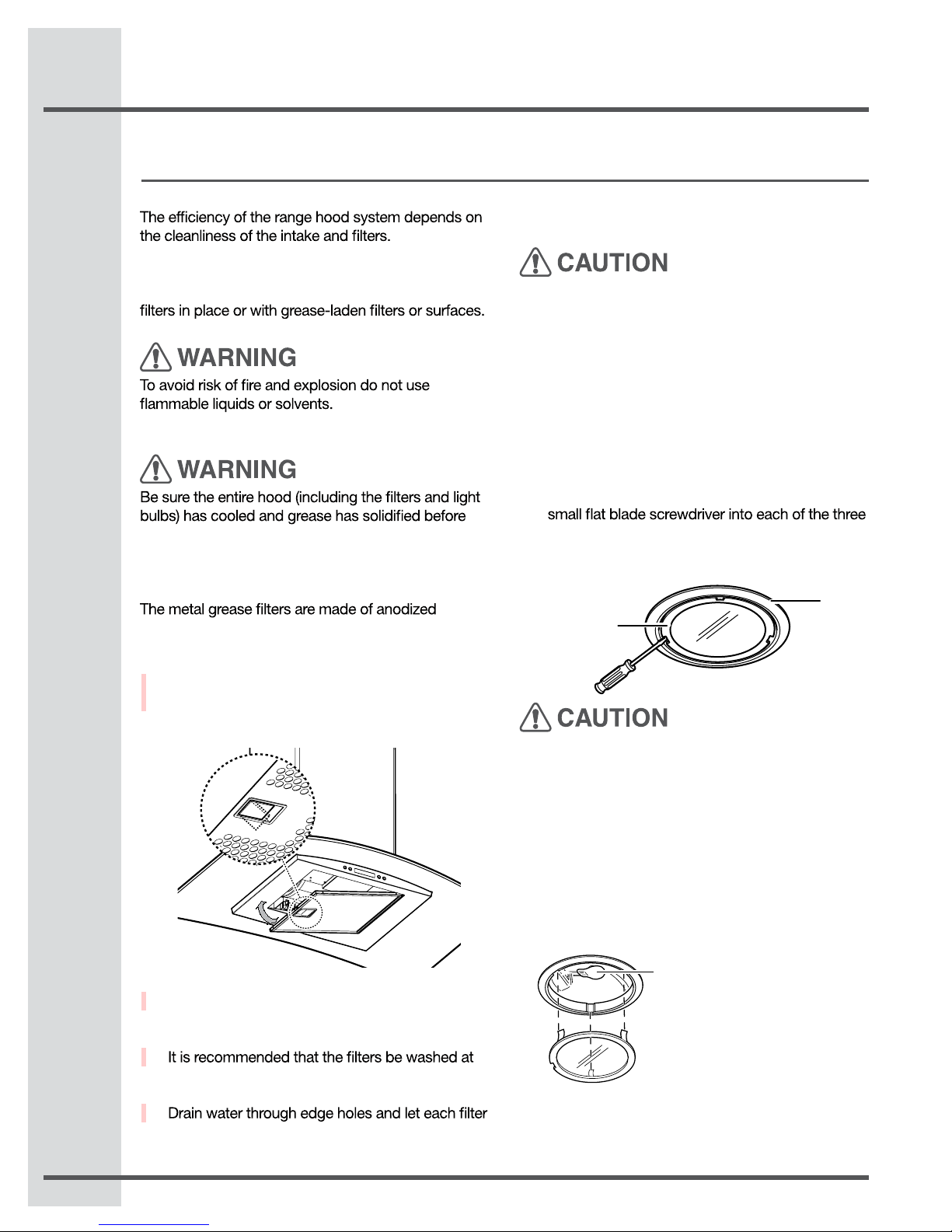
Replace Lights
Remove the inner lamp lens cover by inserting a
•
attempting to clean any part of the appliance.
Filters
aluminum and are long lasting.
To Remove The Metal Grease Filters
Turn the fan and lights off.
•
Pull the spring release handle.
•
To Replace The Metal Grease Filters
Reverse procedure.
•
To Clean Filters
•
least once a month; they can be washed by hand
or in the dishwasher.
•
dry thoroughly before replacing it.
slots and gently prying it free.
NOTE: Do not remove the outer trim ring (lamp
assembly).
Inner
ring
The glass lens and inner trim ring are 2 pieces
loose tting. Be careful when removing the trim
ring that the glass lens does not fall out.
Grasp the bulb and pull it straight out from the
•
lamp socket.
Replace with 120 volt, 40 watt halogen bulbs with
•
a G9 base SUITABLE FOR USE IN OPEN
LUMINAIRES.
Follow package directions, wear gloves, do not
touch bulb with your bare ngers.
Bulb
NOTE: Once you have replaced the light bulb,
make sure to put back the glass in its place.
Replace inner cover by
•
inserting the three
retaining tabs into the
three slots and pressing
them rmly in place.
Outer
ring
Page 19
Care and cleaning
Optional Charcoal Filters
If the model is not vented to the outside, the air will be recirculated through disposable charcoal lters that
help remove smoke and odors.
The charcoal lters cannot be cleaned.
They must be replaced.
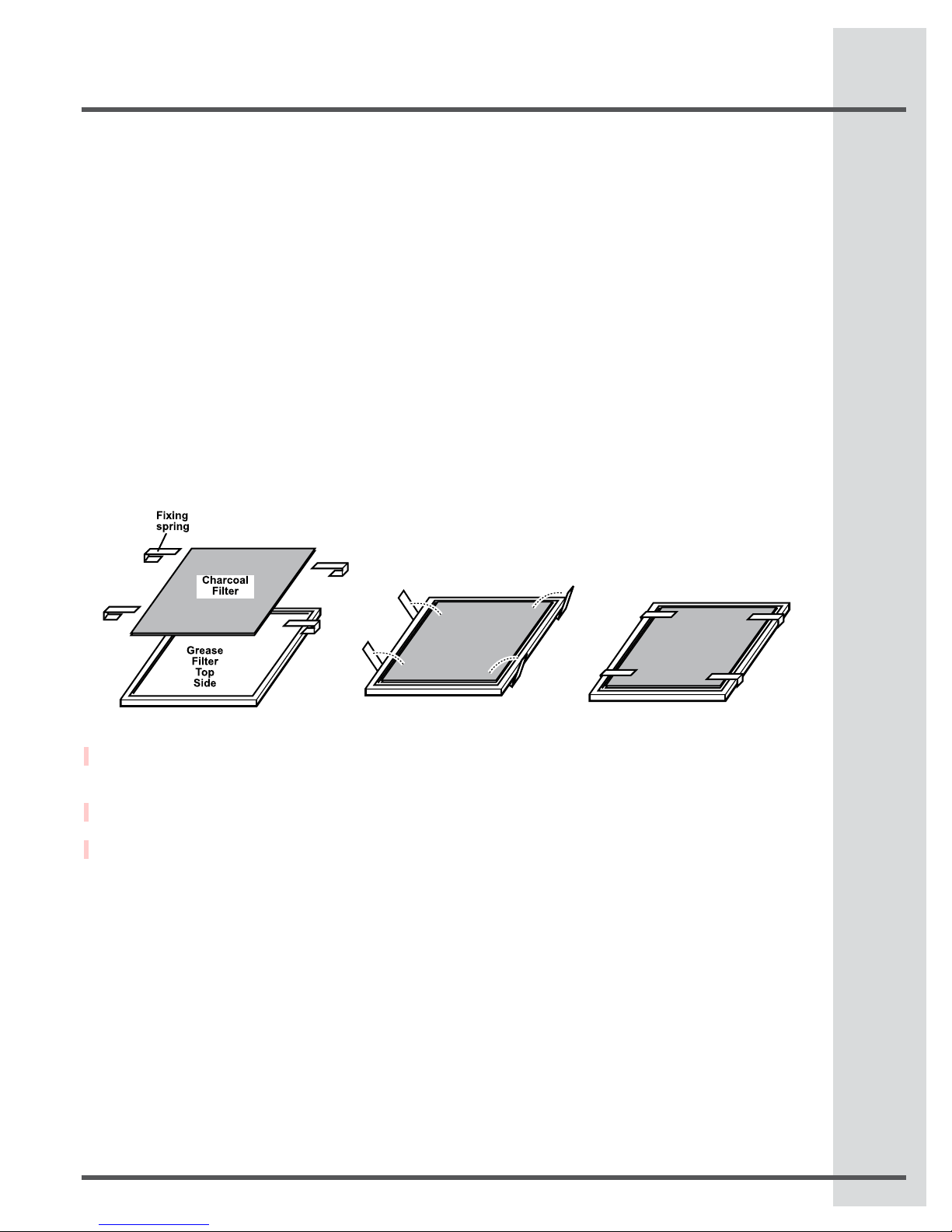
The charcoal lters are clipped inside of each metal grease lter (mounting instructions included with charcoal
lters kit).
NOTE: DO NOT rinse, or put charcoal lters in an automatic dishwasher.
NOTE: Charcoal lters are not included with the hood.
They must be ordered from your supplier.
Order the needed kit specifying your hood model and width size.
Charcoal lter placement (Recirculating accessories)
Fit the charcoal lter mattress on the upper side of each grease lter.
Use provided springs to x it in place.
Note: When removing for replacing for a new one do not remove Fixing Springs, simply pull out one and
rotate outwards.
19
Cleaning
•
Always use the mildest cleaner that will do the
job. Use clean, soft cloths, sponges or paper
towels.
Rub stainless steel nishes in the direction of the
•
grain. Wipe area dry to avoid water marks.
After cleaning, place all parts in their proper
•
positions before using.
The cleaners recommended below indicate a type
and do not constitute an endorsement. Use all
products according to package directions.
Hood Surface
Painted Surfaces: For general care, wipe the outside
of the hood with sudsy water or household cleaners
such as Fantastic or Formula 409, rinse well and dry
with a clean soft cloth to avoid water marks.
Stainless Steel Surfaces: Wipe and dry stainless
steel in the same direction as the grain. Avoid using
too much pressure, which may mar the surface. To
remove nger prints and give added shine, use cleaners such as Stainless Steel Magic. Do not allow
any cleaning compounds to remain in contact with
stainless steel for extended periods.Plastic surfaces:
Wipe wi th a moist soapy sponge.
Rinse and dry.
Aluminum Mesh Filters : Clean lters in the dish
washer or by agitating in sudsy water. Ensure that
there is no soil trapped in the ne mesh. Dry the
lters before reinstalling them.
Anodized Aluminum surfaces: Top cap is not removable. Wash top and underside with hot sudsy water.
Rinse and wipe dry or apply Fantastic® or Formula
409® first tu a clean sponge or paper towel and
wipe clean. DO NOT USE powdered cleansers or
steel wool pads.
Page 20
20
Warranty Information
Your appliance is covered by a one year limited warranty. For one year from your original date of purchase, Electrolux will pay
all costs for repairing or replacing any parts of this appliance that prove to be defective in materials or workmanship when
such appliance is installed, used and maintained in accordance with the provided instructions.
Exclusions
This warranty does not cover the following:
Products with original serial numbers that have been removed, altered or cannot be readily determined.
1.
Product that has been transferred from its original owner to another party or removed outside the USA
2.
or Canada.
Rust on the interior or exterior of the unit.
3.
Products purchased “as-is” are not covered by this warranty.
4.
Food loss due to any refrigerator or freezer failures.
5.
Products used in a commercial setting.
6.
Service calls which do not involve malfunction or defects in materials or workmanship, or for appliances
7.
not in ordinary household use or used other than in accordance with the provided instructions.
Service calls to correct the installation of your appliance or to instruct you how to use your appliance.
8.
Expenses for making the appliance accessible for servicing, such as removal of trim, cupboards,
9.
shelves, etc., which are not a part of the appliance when it is shipped from the fac tory.
Service calls to repair or replace appliance lights bulbs, air lters, waterlters, other consumables , or
10.
knobs, handles, or other cosmetic parts.
Surcharges including, but not limited to, any after hour, weekend, or holiday service calls, tolls, ferry trip
11.
charges, or mileage expense for service calls to remote areas, including the state of Alaska.
Damages to the nish of appliance or home incurred during installation, including but not limited to
12.
doors, cabinets, walls, etc.
Damages caused by: services performed by unauthorized service companies; use of parts other than
13.
genuine Electrolux parts or parts obtained from persons other than authorized service companies; or
external causes such as abuse, misuse, inadequate power supply, accidents, res, or acts of God.
DISCLAIMER OF IMPLIED WARRANTIES; LIMITATION OF REMEDIES
CUSTOMER’S SOLE AND EXCLUSIVE REMEDY UNDER THIS LIMITED WARRANTY SHALL BE PRODUCT
REPAIR OR REPLACEMENT AS PROVIDED HEREIN. CLAIMS BASED ON IMPLIED WARRANTIES,
INCLUDING WARRANTIES OF MERCHANTABILITY OR FITNESS FOR A PARTICULAR PURPOSE, ARE
LIMITED TO ONE YEAR OR THE SHORTEST PERIOD ALLOWED BY LAW, BUT NOT LESS THAN ONE
YEAR. ELECTROLUX SHALL NOT BE LIABLE FOR CONSEQUENTIAL OR INCIDENTAL DAMAGES SUCH
AS PROPERTY DAMAGE AND INCIDENTAL EXPENSES RESULTING FROM ANY BREACH OF THIS
WRITTEN LIMITED WARRANTY OR ANY IMPLIED WARRANTY. SOME STATES AND PROVINCES DO
NOT ALLOW THE EXCLUSION OR LIMITATION OF INCIDENTAL OR CONSEQUENTIAL DAMAGES, OR
LIMITATIONS ON THE DURATION OF IMPLIED WARRANTIES, SO THESE LIMITATIONS OR EXCLUSIONS
MAY NOT APPLY TO YOU. THIS WRITTEN WARRANTY GIVES YOU SPECIFIC LEGAL RIGHTS. YOU MAY
ALSO HAVE OTHER RIGHTS THAT VARY FROM STATE TO STATE.
If You Need
Service
This warranty only applies in the USA and Canada. In the USA, your appliance is warranted by Electrolux Major Appliances
North America, a division of Electrolux Home Products, Inc. In Canada, your appliance is warranted by Electrolux Canada
Corp. Electrolux authorizes no person to change or add to any obligations under this warranty. Obligations for service and
parts under this warranty must be performed by Electrolux or an authorized service company. Product features or specications as described or illustrated are subject to change without notice.
USA
1.800.944.9044
Electrolux Major Appliances
North America
P.O. Box 212378
Augusta, GA 30907
Keep your receipt, delivery slip, or some other appropriate payment record to establish the warranty period
should service be required. If service is performed, it is in your best interest to obtain and keep all receipts.
Service under this warranty must be obtained by contacting Electrolux at the addresses or phone
numbers below.
Canada
1.800.265.8352
Electrolux Canada Corp.
5855 Terry Fox Way
Mississauga, Ontario, Canada
L5V 3E4
Page 21

LI288F
 Loading...