

Electrolux Next Gen 30, 30” GAS FREESTANDING RANGES, 36” GAS FREESTANDING RANGES Service Manual
ELECTROLUX HOME PRODUCTS NORTH AMERICA
SERVICE MANUAL
NEXT GEN
30” & 36” GAS
FREESTANDING RANGES
5995361531
White-Westinghouse
April 2001
1
1111111

SAFE SERVICING PRACTICES - ALL APPLIANCES
To avoid personal injury and/or property damage, it is important that Safe Servicing
Practices be observed. The following are some limited examples of safe practices:
1. DO NOT attempt a product repair if you have any doubts as to your ability to
complete it in a safe and satisfactory manner.
2. Before servicing or moving an appliance:
• Remove the power cord from the electrical outlet, trip the circuit breaker to
the OFF position, or remove the fuse.
• Turn off the gas supply.
• Turn off the water supply.
3. Never interfere with the proper operation of any safety device.
4. USE ONLY REPLACEMENT PARTS CATALOGED FOR THIS APPLIANCE.
SUBSTITUTIONS MAY DEFEAT COMPLIANCE WITH SAFETY
STANDARDS SET FOR HOME APPLIANCES.
5. GROUNDING: The standard color coding for safety ground wires is GREEN,
or GREEN with YELLOW STRIPES. Ground leads are not to be used as current
carrying conductors. It is EXTREMELY important that the service technician
reestablish all safety grounds prior to completion of service. Failure to do so
will create a hazard.
6. Prior to returning the product to service, ensure that:
• All electrical connections are correct and secure
• All electrical leads are properly dressed and secured away from sharp
edges, high-temperature components, and moving parts
• All non-insulated electrical terminals, connectors, heaters, etc. are
adequately spaced away from all metal parts and panels
• All safety grounds (both internal and external) are correctly and securely
connected
• All panels are properly and securely reassembled
ATTENTION!!!
This service manual is intended for use by persons having electrical and mechanical training
and a level of knowledge of these subjects generally considered acceptable in the appliance
repair trade. Electrolux Home Products cannot be responsible, nor assume any liability, for
injury or damage of any kind arising from the use of this manual.
© 2001 White Consolidated Industries
2

Table of Contents
SAFE SERVICING PRACTICES 2
QUICK REFERENCE SHEET 12
MAXIMUM SURFACE TEMPERATURES 13
SECTION A - INSTALLATION INSTRUCTIONS 14 - 34
Installation instructions 30” ranges 14 - 25
Installation instructions 36” ranges 26 - 34
Safety 14
Clearances and Dimensions 14
Fuel types 14
Important notes to installer 15
Important note to consumer 15
Important safety instructions 15
Models with self-clean feature 15
Tools you will need 16
Normal installation steps 16
Anti-tip bracket installation instructions 16
Provide adequate gas supply 17
Seal the openings 17
Connect the range to the gas supply 18
Checking manifold gas pressure 18
Electrical requirements 18
Entension cord precautions 18
Grounding instructions 18
Surface burners 19
Installation of burner cap assembly 19
Electric ignition surface burners 19
Adjusting low setting of surface burner valve 19
Electric ignition burners 19
Air shutter oven burner 19
Air shutter broil burner 19
Make sure the range is level 19
Converting to LP 20 - 25
Tools Required for LP conversion 20
Converting the pressure regulator 21
Converting surface burner to LP 22
Converting the oven and broil burners 23
Reconnect gas and electric supply to range 23
Air sutter ajustment oven and broil burners 24
Installation of new LP/Propane rating/serial plate 25
Conversion to natural gas 25
Safety 26
Dimensions and clearance 26
Important notes to the installer 27
Important safety instructions 27
Provide an adequate gas supply 28
Seal the openings 28
Connecting the range to gas 28
LP gas conversion 29
Pressure regulator conversion 29
Surface burner valves conversion 30
Adjusting low surface burner setting 30
Air adjustment shutter 30
Converting oven burner orifice 31
Converting broil burner orifice 31
Electrical requirements 32
Extension cord cautions 32
3

Grounding instructions 32
Check operation 32
Check igniters 32
Non self clean models 33
Adjusting simmer setting 33
Leveling the range 33
Anti-tip bracket installation 33
SECTION B - GAS FLOW 35 - 38
Gas flow 35
Electric circuits 36
How gas flow system works 37
Troubleshooting 37
Burner flame too large 37
Burner flame too small 37
Burner flame yellow tipped 37
Top burner flame lifts off 37
Top burner spark ignition system 38
How it works 38
Troubleshooting 38
Igniters do not spark 38
Igniter system works normal for all but one valve 38
Igniter sparks at normal rate with all valves turned off 38
Igniter sparks intermittently with all valves turned off 38
SECTION C - ELECTRONIC OVEN CONTROL SYSTEMS 39 - 94
ES 100 oven control system 39 - 43
How to program the ES 100 control 39
To set the clock 39
To set the minute timer 39
To change the minute timer while in use 39
To set the control for baking 39
To change the oven temperature after baking has started 40
To set the oven control for broil 40
How the ES 100 system operates 40
Bake 40
Broil 41
Calibration 41
To change calibration 41
Troubleshooting 41
F1 code 41
F3 code 41
Control will not program 42
Blank display 42
No heat 42
Sample schematic for ES 100 control system 43
Es 200 oven control system 44 - 51
How to program the ES 200 44
Temperature conversion 44
To set the clock 44
To set the minute timer 44
To change the minute timer while in use 45
To set the control for baking 45
To change the oven temperature after baking has started 45
To set the control for continuous bake or 12 hour energy saving 45
To set the control for oven lockout feature 45
To set the control to broil 45
To set the control for a self-clean cycle 46
When the self-clean cycle is complete 46
4

Stopping or interrupting a self-cleaning cycle 46
How the ES 200 operates 46
Bake 46
Broil 47
Clean 47
Calibration 47
To change the calibration 47
Troubleshooting 48
F1 code 48
F3 code 48
F9 code 48
Control will not program 48
Blank display 48
No heat 48
Control operates normally but bake & broil burners do not heat 48
Broil burner operates but bake does not heat 49
Bake burner operates but broil does not heat 49
Self-cleaning 49
Oven door does not lock when the
oven is programmed for clean 49
Oven door locks when the oven is programmed
for clean but the oven does not heat 49
Lock motor runs continuously 49
Door latch is partly closed with the door open 49
Sample schematic for ES 200 control system 50
The ES 300 electronic oven control system 51
How to program the ES 300 system 51
For a silent control panel 51
Temperature conversion 51
To set the clock 51
To set the minute timer 51
To change the minute timer while it is in use 52
To cancel the minute timer before the set time has run out 52
To set the controls for bake 52
To change the oven temperature after baking has started 52
To set control for continuous bake or 12 hour energy saving 52
To set the control oven lockout 52
To set the timed bake feature 52
To program the oven to begin baking immediately
and shut off automatically 53
To program oven for a delay start
time and to shut-off automatically 53
When the set bake time runs out 53
To change the oven temperature or
bake time after baking has started 53
Speed bake 53
General cooking instructions 53
To set speed bake cooking system 54
To Broil 54
Self-cleaning oven 54
To start the self-clean cycle 55
When the self-clean cycle is completed 55
How the ES 300 control system works 55
Bake 55
Time bake 56
Speed bake 56
Broil 56
5

Clean 56
Calibration 57
To change the calibration 57
Troubleshooting 57
F1 code 57
F3 code 57
F9 code 57
Control will not program 57
Time bake does not operate 57
Blank display 57
No heat 58
Broil burner operates but bake burner does not 58
Bake burner operates but broil burner does not 58
Fan in oven does not run when speed bake switch is turned on 58
Self-cleaning 59
Oven door locks but oven does not heat in clean 59
Lock motor runs continuously 59
Door latch is partly closed with door open 59
Sample schematic for ES 300 control system 60
The ES 400 electronic oven control system 61
How to program the ES 400 61
Clock 61
To set the clock 61
Changing between 12 or 24 hour time of day display 61
To set the control for continuous bake or 12 hour energy saving 61
Minute timer 61
To set the minute timer 62
To change the minute timer while in use 62
To cancel the minute
timer before the set time has run out 62
Oven lockout feature 62
To active the oven lockout 62
To reactivate oven operation 62
Temperature display Fahrenheit or Celsius 62
Silent control operation 62
To change from sound to silent operation 62
Preheat 62
To change preheat temperature while oven is preheating 63
Bake 63
Time bake 63
To program the oven to begin baking
immediately and to shut off automatically 63
To program oven for a delayed start
time and to shut-off automatically 64
Broil 64
To set the oven to broil at 550 degrees F. 64
Convection bake 65
Convection roast 65
To start the self-clean cycle 65
To set the controls for the self-cleaning cycle
to start immediately and shut off automatically 65
When the self-clean cycle is completed 66
Stopping or interrupting a self-cleaning cycle 66
How the ES 400 operate 66
Preheat 66
Bake 67
Time bake 67
6

Convection bake 67
Convection roast 67
Broil 68
Clean 68
Calibration 68
To check oven calibration 68
To adjust the oven temperature higher 68
To adjust the oven temperature lower 68
Troubleshooting 68
F1 code 68
F3 code 69
F9 code 69
Control will not program 69
Time bake does not operate 69
Convection bake 69
Blank display 69
No heat 69
Bake and broil burner does not heat 70
Broil burner operates but bake burner does not heat 70
Bake burner operates but broil burner does not heat 70
Self-cleaning 70
Oven door does not lock when the
oven is programmed for clean 70
Oven door locks when the oven is
programmed for clean but oven does not heat 70
Lock motor runs continuously 70
Sample schematic for ES 400 control system 72
The ES 450 electronic oven control system 73
How to program the ES 450 73
Clock 73
Changing between 12 or 24 hour time of day display 73
Continuous bake or 12 hour energy saving 73
Minute timer 74
To change the minute timer while it is in use 74
To cancel the minute timer before the set time has run out 74
Oven lockout feature 74
To active the oven lockout 74
To reactivate oven operation 74
Temperature display Fahrenheit or Celsius 74
To change from Fahrenheit to Celsius 74
Silent control operation 74
To change from sound operation to silent operation 74
Preheat 75
Bake 75
Time bake 75
To program the oven to begin baking
immediately and to shut off automatically 75
To program oven for a delay start time
and to shut-off automatically 76
Broil 76
To set oven to broil 76
Convection bake 77
Setting food catagory feature 77
Self-clean 77
To set the control for the self-cleaning cycle to
start immediately and shut off automatically 78
When the self-clean cycle is complete 78
7

Stopping or interrupting a self-cleaning cycle 78
To set the controls for the self-cleaning cycle to start
at a delayed time and shut off automatically 78
When the self-clean cycle has completed 78
How the ES 450 operates 78
Preheat 78
Bake 79
Time bake 79
Convection bake 79
Fixed setting 80
Meats 80
Cakes 80
Breads 80
Broil 80
Clean 80
Calibration 80
To check oven calibration 80
To change calibration 80
Troubleshooting 81
F1 code 81
F3 code 81
F9 code 81
Control will not program 81
Time bake does not operate 81
Convection bake 81
Neither the fan motor or the assist element operate 81
Fan motor does not operate 81
Assist element does not operate 81
Blank display 81
No heat 82
Control operates normally but the
bake and broil burners do not heat 82
Broil burner operates but bake burner does not heat 82
Bake burner operates but broil burner does not heat 82
Self-cleaning 82
Oven door does not lock when the oven
is programmed for clean 82
Oven door locks when the oven is
programmed for clean but the oven does not heat 83
Lock motor runs continuously 83
Door latch is partly closed with door open 83
Sample schematic for ES 450 Control system 84
Electronic oven control system for 36” self-cleaning gas ranges 85
How to program the 36” gas range control 85
For a silent control panel 85
Temperature conversion Fahrenheit/Celsius 85
Lockout 85
Sabbath feature 85
To set the clock 86
To set the minute timer 86
To change the minute timer 86
To cancel the minute timer before the set time has run out 86
To set the preheat temperature 87
To set the control for normal baking 87
To set or change temperature 87
To set automatic timer 87
To start heating immediately and shut-off automatically 87
8

Once the oven controls are set 87
For a delayed start time and shut-off automatically 88
To broil 88
To set the oven control for self-clean cycles 88
Calibrating oven temperature 89
How the electronic oven control system on a 36” gas range operates 89
Preheat 89
Bake 90
Broil 90
Clean 90
Calibration 91
To change calibration 91
Troubleshooting 91
F1 code 91
F3 code 91
Door code 91
Control will not program 91
Blank display 91
No heat 92
Control operates normally but the bake
and broil burners do not heat 92
Broil burner operates but the bake burner does not heat 92
Bake burner operates but the broil burner does not heat 92
Self-cleaning 92
Oven does not heat in self-clean 92
Oven heats in self-clean but the oven is not clean 92
Sample schematic for 36” gas range 93
Warmer drawer 94
To set the warmer drawer control 94
How the warmer drawer circuit works 94
Troubleshooting 94
If the element does not heat 94
If the element heats during preheat then stays off
until the temperature drops to about 130 degrees 95
Element does not cycle off 95
Warmer drawer is slow to preheat 95
Warmer drawer heats but indicator light does not glow 95
SECTION D - DISASSEMBLY AND REPLACEMENT OF PARTS 96 - 129
30” gas ranges 96 - 112
Removing backguard back panel 96
Removing infinite switches 96
Removing indicator light 97
Removing electronic oven control 97
Removing oven light switch 97
Removing the control panel 97
Removing the end cap 97
Removing the main top 98
Removing sealed burner base 99
Removing top burner igniter 99
Removing fixed top orifice sealed burner 99
Removing manifold panel sealed burners 99
Removing burner pan 100
Removing top burner igniter switches 100
Removing top burner valve 100
Removing the manifold pipe 101
Removing the latch mechanism 101
Oven door 101
9

Removing oven door seal 101
Removing oven door 101
Door hinge adjustment 102
Removing the hinge opening cover 102
Removing the door hinge 102
Removing the upper door trim 102
Removing door handle 102
Removing outer door glass trim 103
Removing center door glass 103
Removing door wool shield 103
Removing glass package and inner door liner 103
Removing oven bottom 103
Removing bake burner baffle 103
Removing bake burner igniter 104
Removing bake burner (self-clean models) 104
Removing burner heat shield (self-clean models) 104
Convection and speed bake models 105
Removing fan cover 105
Removing fan blade 105
Removing convection assist element 105
Removing broil burner and baffle (self-clean models) 106
Removing broil igniter 106
Removing oven vent (self-clean models) 106
Removing oven safety valve (self-clean models) 106
Components removed from the rear of the range 107
Removing rear manifold cover 107
Removing back cover 107
Removing heat shield 107
Removing pressure regulator 108
Removing top burner igniter spark module 108
Removing lock motor assembly 108
Removing oven sensor 109
Door switch and rod removal 109
Removing convection and speed bake motor assemblies 109
Removing bodyside panels 110
Storage drawer 111
Removing storage drawer front panel 111
Removing inside drawer panel 111
Removing drawer glides 111
Removing the warmer drawer 111
Removing the warmer drawer side rails 112
Removing warmer drawer low limit thermostat 112
Removing the warmer drawer element 112
36” gas range 113 - 129
Removing backguard glass and trim 113
Removing control buttons 113
Removing electronic oven control 113
Removing fluorescent lamp starter 113
Removing starter base 113
Removing fluorescent ballast 114
Removing oven light or fluorescent light switch 114
Removing backguard trim 114
Removing back panel of backguard 115
Removing fluorescent lamp socket 116
Removing splasher panel 116
Removing grates, griddle cover griddle fifth burner pan and main top 116
Removing pressure regulator 116
10

Removing top burners 117
Removing top burner igniters 117
Removing main top support rod 117
Removing top burner knobs 118
Removing control panel 118
Removing top burner igniter switch 118
Removing top burner valves 118
Removing manifold pipe 119
Removing the latch handle knob 119
Removing lock mechanism cover 119
Removing lock mechanism arm 119
Removing lock switch arm 120
Removing lock mechanism 120
Removing burner box side panels 120
Removing the burner box 121
Oven door 121
Removing oven door seal 121
Oven door removal 121
Removing the oven door trim 121
Removing oven door handle 122
Removing door glass 122
Removing top outer glass spacers 122
Removing center door glass 122
Removing the wool shield 122
Removing the glass package 123
Removing inner door liner 123
Removing oven door springs 123
Removing oven door hinge 123
Removing storage drawer 123
Removing storage drawer handle 123
Removing storage drawer panel 124
Removing storage drawer rollers 124
Removing storage drawer rails 124
Removing storage drawer front panel 124
Removing the oven bottom 125
Removing bake burner baffle 125
Removing bake burner igniter 125
Removing bake burner 125
Removing the bake burner pan 125
Removing oven valve cover 126
Removing oven safety valve 126
Removing broil burner 126
Removing the broil burner igniter 127
Removing broil burner baffle 127
Removing oven vent 127
Removing oven light cover 128
Removing oven light bazel 128
Removing oven light socket 128
Removing rear cover 128
Removing oven sensor 128
Removing spark module 129
Removing lock switch 129
Removing bodyside panels 129
11

QUICK REFERENCE SHEET
1. Serial number breakdown: V F 1 2 3 1 8 4 7 2
Incremented unit number
Production week
Last digit of production year
Product identification
Manufacturing Facility
RTD SCALE
Temperature °F Resistance in Ohms
32 +/- 1.9 1000 +/- 4.0
75 +/- 2.5 1091 +/- 5.3
250 +/- 4.4 1453 +/- 8.9
2. Oven sensor resistance chart:
350 +/- 5.4 1654 +/- 10.8
450 +/- 6.9 1852 +/- 13.5
550 +/- 8.2 2047 +/- 15.8
650 +/- 9.6 2237 +/- 18.5
900 +/- 13.6 2697 +/- 24.4
3. Oven igniter current spec: 3.2 to 3.6 amps
12

MAXIMUM SURFACE TEMPERATURES (allowed for gas and electric ranges)
When Electrolux tests side panels and doors for skin temperature, certain U.L. and/or A.G.A. guide
lines must be followed.
1. Product must be undamaged, correctly assembled and have the correct oven temperature.
2. All skin temperatures are based on a room temperature of 77°F (25°C) and an oven set temperature of
400°F.
3. Oven must be cycling at 400°F for one hour before test is conducted.
4. Pyrometers, (temperature testers), must be of high quality and properly adjusted.
5. An increase or decrease of 1°F in the room ambient temperature, will allow a 1°F increase or decrease
in the maximum allowable surface temperature of the range.
Side Panel, Painted 152°F
Side Panel, Porcelain 160°F
Oven Door, Glass 172°F
Oven Door, Painted 152°F
Oven Door, Porcelain 160°F
Warmer Drawer, Painted 152°F
Warmer Drawer, Porcelain 160°F
Cooktop No Temperature Limits Apply
Lower Console No Temperature Limits Apply
Oven Vent Area No Temperature Limits Apply
Knobs and Handles Skirt
Plastic* Metal Plastic* Metal
Conventional Gas & Electric 167°F 131°F 182°F 152°F
Self-Clean Gas at Clean Temperature 167°F 131°F 182°F 152°F
Self-Clean Gas at Clean Temperature 182°F 152°F 182°F 152°F
* Includes plastic with metal plating not more than 0.005" thick and metal with a plastic or vinyl covering not
less than 0.005" thick
13

SECTION A - 30" GAS RANGE INSTALLATION INSTRUCTIONS
INSTALLATION AND SERVICE MUST BE PERFORMED BY A QUALIFIED INSTALLER.
IMPORTANT: SAVE FOR LOCAL ELECTRICAL INSPECTOR'S USE.
READ AND SAVE THESE INSTRUCTIONS FOR FUTURE REFERENCE.
If the information in this manual is not followed
exactly, a fire or explosion may result causing property damage,
personal injury or death.
FOR YOUR SAFETY:
— Do not store or use gasoline or other flammable vapors and
liquids in the vicinity of this or any other appliance.
— WHAT TO DO IF YOU SMELL GAS:
• Do not try to light any appliance.
• Do not touch any electrical switch; do not use any phone in
your building.
• Immediately call your gas supplier from a neighbor's phone.
Follow the gas supplier's instructions.
• If you cannot reach your gas supplier, call the fire department.
— Installation and service must be performed by a qualified
installer, service agency or the gas supplier.
Clearances and Dimensions
1. Location—Check location
where the range will be
installed. Check for proper
electrical and gas supply,
and the stability of the floor.
2. Dimensions that are shown
must be used. Given
dimensions provide
minimum clearance. Contact
surface must be solid and
level.
Provide Proper Fuel Type
Before Proceeding: Your range is preset to operate on natural
gas only. Some models are shipped convertible with parts and
conversion instructions supplied. Other models have a LP/Propane
Conversion Kit available through your dealer.
DO NOT attempt to convert this range to LP/Propane
settings without the proper LP/Propane conversion kit provided with
the range or obtained from your dealer. Follow all instructions
provided with the conversion kit.
14

Important Notes to the Installer
1. Read all instructions contained in these installation
instructions before installing range.
2. Remove all packing material from the oven
compartments before connecting the gas and
electrical supply to the range.
3. Observe all governing codes and ordinances.
Never leave children alone or
unattended in the area where an appliance is in
use. As children grow, teach them the proper, safe use
of all appliances. Never leave the oven door open when
the range is unattended.
Stepping, leaning or sitting on the
doors or drawers of this range can result in serious
injuries and can also cause damage to the range.
4. Be sure to leave these instructions with the
consumer.
Important Note to the Consumer
1. Keep these instructions with your owner's guide for
future reference.
IMPORTANT SAFETY INSTRUCTIONS
Installation of this range must conform with local codes
or, in the absence of local codes, with the National Fuel
Gas Code ANSI Z223.1—latest edition when installed
in the United States.
This range has been design certified by CSA
International. As with any appliance using gas and
generating heat, there are certain safety precautions
you should follow. You will find them in the Use & Care
Manual, read it carefully.
• Be sure your range is installed and grounded
properly by a qualified installer or service
technician.
• This range must be electrically grounded in
accordance with local codes or, in their
absence, with the National Electrical Code
ANSI/NFPA No .70—latest edition when
installed in the United States. See Grounding
Instructions on page 19.
• Before installing the range in an area covered
with linoleum or any other synthetic floor
covering, make sure the floor covering can
withstand heat at least 90°F above room
temperature without shrinking, warping or
discoloring. Do not install the range over carpeting
unless you place an insulating pad or sheet of 1/4inch thick plywood between the range and carpeting.
• Make sure the wall coverings around the range
can withstand the heat generated by the range.
• Do not obstruct the flow of combustion air at
the oven vent nor around the base or beneath
the lower front panel of the range. Avoid touching
the vent openings or nearby surfaces as they may
become hot while the oven is in operation. This
range requires fresh air for proper burner
combustion.
• Do not store items of interest to children in the
cabinets above the range. Children could be
seriously burned climbing on the range.
• To eliminate the need to reach over the surface
burners, cabinet storage space above the
burners should be avoided.
• Adjust surface burner flame size so it does not
extend beyond the edge of the cooking utensil.
Excessive flame is hazardous.
• Do not use the oven as a storage space. This
creates a potentially hazardous situation.
• Never use your range for warming or heating
the room. Prolonged use of the range without
adequate ventilation can be dangerous.
• Do not store or use gasoline or other flammable
vapors and liquids near this or any other
appliance. Explosions or fires could result.
• Reset all controls to the "off" position after
using a programmable timing operation.
FOR MODELS WITH SELF-CLEAN FEATURE:
• Remove broiler pan, food and other utensils
before self-cleaning the oven. Wipe up excess
spillage. Follow the precleaning instructions in the
Owner's Guide.
• Unlike the standard gas range, THIS COOKTOP
IS NOT REMOVABLE. Do not attempt to remove
the cooktop.
DO NOT MAKE ANY ATTEMPT TO
OPERATE THE ELECTRIC IGNITION OVEN DURING
AN ELECTRICAL POWER FAILURE. RESET ALL OVEN
CONTROLS TO "OFF" IN THE EVENT OF A POWER
FAILURE.
The electric ignitor will automatically re-ignite the oven
burner when power resumes if the oven thermostat
control was left in the "ON" position.
When an electrical power failure occurs during use, the
surface burners will continue to operate.
During a power outage, the surface burners can be lit
with a match. Hold a lighted match to the burner, then
slowly turn the knob to the LITE position. Use extreme
caution when lighting burners this way.
15

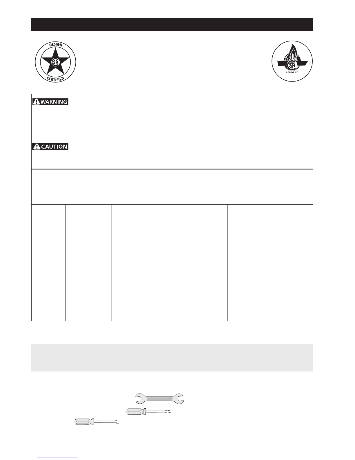
Before Starting - Tools You Will Need
For Leveling Legs and Anti-Tip Bracket:
• Adjustable wrench or channel lock pliers
• 5/16" Nutdriver or Flat Head Screw Driver
• Electric Drill & 1/8" Diameter Drill Bit (5/32" Masonry
Drill Bit if installing in concrete)
For gas supply connection:
• Pipe wrench
Important Safety Warning:
To reduce the risk of tipping of the range, the range must
be secured to the floor by a properly installed anti-tip
bracket and screws packed with the range. Failure to
install the anti-tip bracket will allow the range to tip over
if excessive weight is placed on an open door or if a child
climbs upon it. Serious injury might result from spilled
hot liquids or from the range itself.
If range is ever moved to a different location, the antitip brackets must also be moved and installed with the
range.
Instructions are provided for installation in wood or
cement fastened to either the floor or wall. When
installed to the wall, make sure that screws completely
penetrate dry wall and are secured in wood or metal.
When fastening to the floor or wall, be sure that screws
do not penetrate electrical wiring or plumbing.
For burner flame adjustment:
• Phillips head and
blade-type screwdrivers
For gas conversion (LP/Propane or Natural):
• Open end wrench - 1/2"
Additional Materials You Will Need:
• Gas line shut-off valve
• Pipe joint sealant that resists action of LP/Propane
gas
• A new flexible metal appliance conduit (1/2" NPT
x 3/4" or 1/2" I.D.) must be design certified by CSA
International. Because solid pipe restricts moving
the range we recommend using a new flexible
conduit (4 to 5 foot length) for each new installation
and additional reinstallations.
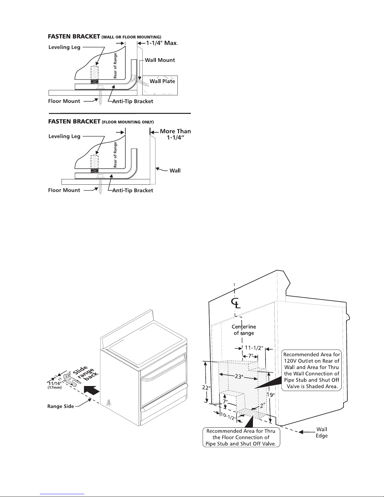
A. Locate the Bracket Using the Template - (Bracket
may be located on either the left or right side of the
range. Use the information below to locate the
bracket if template is not available). Mark the floor
or wall where left or right side of the range will be
located. If rear of range is against the wall or no
further than 1-1/4" from wall when installed, you
may use the wall or floor mount method. If molding
is installed and does not allow the bracket to fit
flush against the wall, remove molding or mount
bracket to the floor. For wall mount, locate the
bracket by placing the back edge of the template
against the rear wall and the side edge of template
on the mark made referencing the side of the
range. Place bracket on top of template and mark
location of the screw holes in wall. If rear of range
is further than 1-1/4" from the wall when installed,
attach bracket to the floor. For floor mount, locate
the bracket by placing back edge of the template
where the rear of the range will be located. Mark
the location of the screw holes, shown in template.
• Always use the (2) new flare union adapters (1/2"
NPT x 3/4" or 1/2" I.D.) supplied with the new
flexible appliance conduit for connection of the
range.
Normal Installation Steps:
1. Anti-Tip Bracket Installation Instructions
B. Drill Pilot Holes and Fasten Bracket - Drill a 1/8"
pilot hole where screws are to be located. If bracket
is to be mounted to the wall, drill pilot hole at an
approximate 20° downward angle. If bracket is to be
mounted to masonry or ceramic floors, drill a 5/32"
pilot hole 1-3/4" deep. The screws provided may be
used in wood or concrete material. Use a 5/16" nutdriver or flat head screwdriver to secure the bracket
in place.
16
pressure. A convertible pressure regulator is connected
to the manifold and MUST be connected in series with
the gas supply line. If the LP/Propane conversion kit has
been used, follow instructions provided with the kit for
converting the pressure regulator to LP/Propane use.
Care must be taken during installation of range not to
obstruct the flow of combustion and ventilation air.
For proper operation, the maximum inlet pressure to
the regulator should be no more than 14 inches of water
column pressure. The inlet pressure to the regulator
must be at least 1 inch greater than regulator manifold
pressure. Examples: If regulator is set for natural gas
4 inch manifold pressure, inlet pressure must be at
least 5 inches; if regulator has been converted for LP/
Propane gas 10 inch manifold pressure, inlet pressure
must be at least 11 inches.
Leak testing of the appliance shall be conducted
according to the instructions in step 4g.
C. Level and Position Range
Level range by adjusting the (4) leveling legs with a
wrench. Note: A minimum clearance of 1/8" is
required between the bottom of the range and the
leveling leg to allow room for the bracket. Use a spirit
level to check your adjustments. Slide range back
into position. Visually check that rear leveling leg is
inserted into and fully secured by the Anti-Tip
Bracket by removing lower panel or storage drawer.
For models with a warmer drawer or broiler
compartment, grasp the top rear edge of the range
and carefully attempt to tilt it forward.
The gas supply line should be 1/2" or 3/4" I.D.
3. Seal the openings.
Seal any openings in the wall behind the range and in the
floor under the range after gas supply line is installed.
2. Provide an adequate gas supply.
This unit is pre-set to operate on 4" natural gas manifold
17

4. Connect the range to the gas supply.
To prevent leaks, put a pipe joint sealant on all male
(outside) pipe threads. The regulator is in the location
shown below.
Do not allow regulator to turn on
pipe when tightening fittings.
f) Make sure service shut-off valve on pressure
regulator is in "ON" position.
g) Check for leaks. Turn the gas supply on to the
range and use a liquid leak detector at all joints
and conduits to check for leaks in the system.
Do not use a flame to check for gas
leaks.
Checking Manifold Gas Pressure
See page 23.
5. Read electrical connection details below and
connect electricity to range.
Before servicing, disconnect
electrical supply at circuit breaker, fuse or power
cord.
Electric Requirements:
An individual, properly grounded and polarized branch
circuit protected by a 15 amp. circuit breaker or time
delay fuse. See serial plate for proper voltage.
a) Install an external manual gas shut-off valve to
gas supply line in an easily-accessible location
outside of the range. Be sure you know how and
where to shut-off the gas supply to the range.
b) Attach appliance conduit to flare union on
regulator.
c) Attach appliance conduit to the flare union on
the regulator.
d) Install flare union adapter to external manual
shut-off valve.
e) Attach appliance conduit to flare union on shut-
off valve.
Extension Cord Precautions:
Because of potential safety hazards under certain
conditions, we strongly recommend against the use of
any extension cord. However, if you still elect to use an
extension cord, it is absolutely necessary that it be a UL
listed 3-wire grounding type appliance extension cord
and that the current carrying rating of the cord in amperes
be equivalent to or greater than the branch circuit rating.
Such extension cords are obtainable through your local
service organization.
PLEASE READ CAREFULLY! For
personal safety, this product must be properly
grounded.
Grounding Instructions:
The power cord of this appliance is equipped with a
3-prong (grounding) plug which mates with a standard
3-prong grounding wall receptacle to minimize the
possibility of electric shock hazard from this appliance.
The customer should have the wall receptacle and
circuit checked by a qualified electrician to make sure
the receptacle is properly grounded and polarized.
Where a standard two-prong wall receptacle is
encountered, it is the personal responsibility and
obligation of the customer to have it replaced with a
properly grounded three-prong wall receptacle.
18
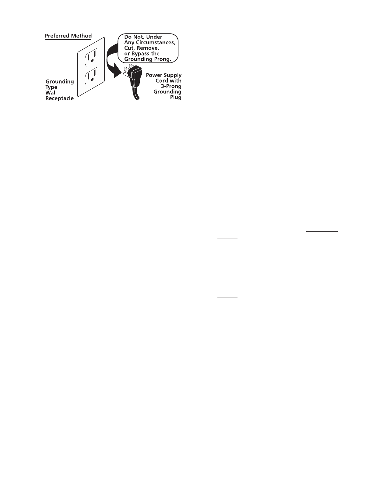
DO NOT, UNDER ANY CIRCUMSTANCES, CUT OR
REMOVE THE THIRD (GROUND) PRONG FROM
THE POWER CORD.
Surface Burners:
See Page 21.
6. Installation of Burner Cap Assembly
See Page 22.
9. Electric Ignition Burners:
Operation of electric igniters should be checked after
range and supply line connectors have been carefully
checked for leaks and range has been connected to
electric power.
The oven burner is equipped with an electric control
system as well as an electric oven burner igniter. If your
model is equipped with a waist-high broil burner, it will
also have an electric burner igniter. These control systems
require no adjustment. When the oven is set to operate,
current will flow to the igniter. It will "glow" similar to a
light bulb. When the igniter has reached a temperature
sufficient to ignite gas, the electrically controlled oven
valve will open and flame will appear at the oven burner.
There is a time lapse from 30 to 60 seconds after the
thermostat is turned ON before the flame appears at the
oven burner. When the oven reaches the dial setting, the
glowing igniter will go off. The burner flame will go "out"
in 20 to 30 seconds after the igniter goes "OFF." To
maintain any given oven temperature, this cycle will
continue as long as the dial (or display) is set to operate.
7. Electric Ignition Surface Burners
Operation of electric igniters should be checked after
range and supply line connectors have been carefully
checked for leaks and range has been connected to
electric power.
a) To check for proper lighting, push in and turn
a surface burner knob counterclockwise to the
LITE position. You will hear the igniter sparking.
b) The surface burner should light when gas is
available to the top burner. Purge air from supply
lines by leaving knob in the LITE position until
burner ignites. Each burner should light within
four (4) seconds in normal operation after air has
been purged from supply lines.
c) Visually check that burner has lit. Once the
burner lights, the control knob should be turned
out of the LITE position.
d) There are separate electrodes (igniters) for each
burner. Try each knob separately until all burner
valves have been checked.
e) If burner goes out, reset control to OFF.
8. Adjust the "LOW" Setting of Surface Burner
Valve (Linear Flow Valves Only):
See Page 23.
Operation of Oven Burners and Oven Adjustments
After removing all packing materials and literature
from the oven:
a) Set oven to BAKE at 300ºF. See Use & Care
Manual for operating instructions.
b) Within 60 seconds the oven burner should
ignite. Check for proper flame, and allow the
burner to cycle once. Reset controls to off.
c) If your model is equipped with a waist-high
broiler, set oven to BROIL. See Use & Care
Manual for operating instructions.
d) Within 60 seconds the broil burner should ignite.
Check for proper flame. Reset controls to off.
10. Air Shutter-Oven Burner
See Page 24
11. Air Shutter-Broil Burner
See page 24
12. Make Sure Range is Level.
Level the range by placing a level horizontally on an oven
rack. Check diagonally from front to back, then level the
range by either adjusting the leveling legs or by placing
shims under the corners of the range as needed.
13. After installation is complete, make sure all
controls are left in the OFF position.
19
Instructions for converting range to operate on Liquefied Petroleum Gas
INSTALLATION AND SERVICE MUST BE PERFORMED BY
A QUALIFIED INSTALLER.
IMPORTANT: SAVE FOR LOCAL ELECTRICAL INSPECTOR'S USE.
READ AND SAVE THESE INSTRUCTIONS FOR FUTURE REFERENCE.
This conversion kit must be installed by a qualified service technician in accordance with
the manufacturer's instructions and all applicable codes and requirements of the authority having
jurisdiction. Failure to follow instructions may result in fire, explosion or production of carbon monoxide
causing property damage, personal injury or loss of life. The qualified service agency is responsible for
the proper installation of this kit. The installation is not proper and complete until the operation of the
converted appliance is checked as specified in the manufacturer's instructions supplied with this kit.
Before proceeding with the conversion, shut off the gas supply before disconnecting
electrical power to the range. Be sure both power supplies are off before installing the conversion kit.
Failure to do so could cause serious bodily injury.
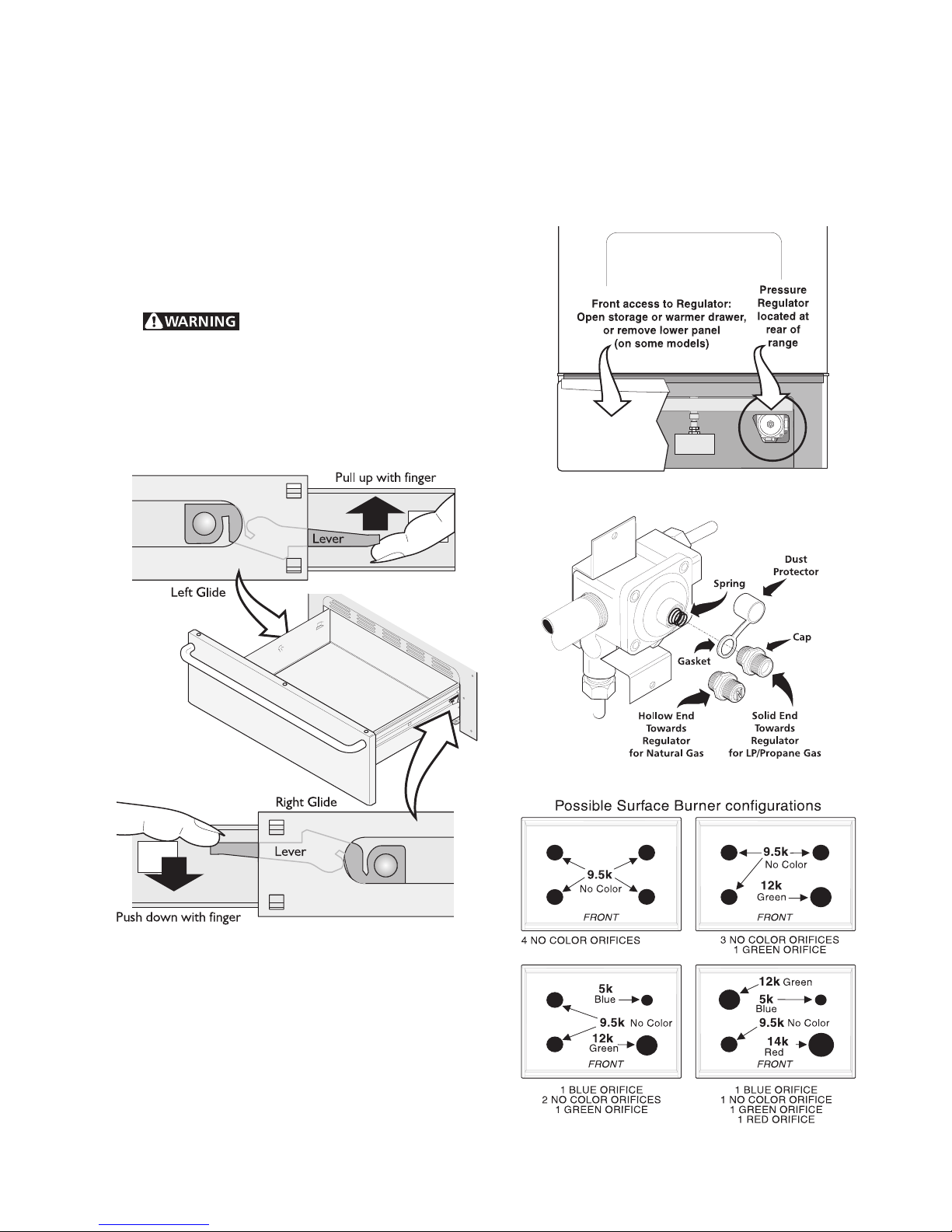
Determine the combination of top burners that are featured on your range. Then identify the parts you
need from this kit to completethe LP conversion. When burners are converted from Natural to LP the BTU
rating is as follows:
5,000 BTU* Natural Gas to 4,500 BTU* LP Gas 9,500 BTU* Natural Gas to 8,000 BTU* LP Gas
12,000 BTU* Natural Gas to 10,000 BTU* LP Gas 14,000 BTU* Natural Gas to 11,000 BTU* LP Gas
Quantity Part Number Part Description Notes
1 316037526 L.P. Conversion Kit Label English & French
1 316248105 Instructions for converting range to LP Gas English, French & Spanish
1 316005215 Rating Plate - English 4 - 8K
1 316005216 Rating Plate - English 3 + 1
1 316005217 Rating Plate - English 2 + 1 + 1
1 316005218 Rating Plate - English 1 + 1 + 1 + 1
1 316005219 Rating Plate - French 4 - 8K
1 316005220 Rating Plate - French 3 + 1
1 316005221 Rating Plate - French 2 + 1 + 1
1 316005222 Rating Plate - French 1 + 1 + 1 + 1
1 316241200 L.P. Conversion Label English, French & Spanish
1 316237904 Orifice - 11,000 BTU* RED
1 316237905 Orifice - 10,000 BTU* GREEN
1 316237906 Orifice - 8,000 BTU* NO COLOR
1 316237907 Orifice - 4,500 BTU* BLUE
*Note: For operation at elevations above 2000 ft., appliance rating shall be reduced at the rate of 4 percent
for each 1000 ft. above sea level.
IMPORTANT: After replacing the natural gas to LP orifices, be sure to keep the original factory installed
natural gas orifices for future range conversion back to natural gas. The factory orifices are marked with
101 for 5,000 BTU; 154 for 9,500 BTU; 175 for 12,000 BTU and 193 for 14,000 BTU.
Tools Required for L.P. Conversion:
3/8", 1/2" and 5/8" Open End Wrench
1/8" Wide Flat Blade Screwdriver
7mm Nutdriver
20
How to Convert the Range for use with LP/Propane
Gas
1. Convert the Pressure Regulator
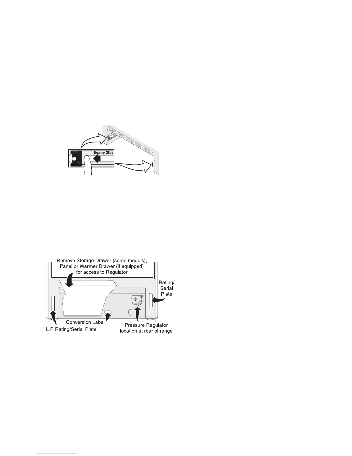
To access the gas regulator, remove the storage drawer
or warmer drawer. If equipped with a storage drawer,
open and remove the drawer completely. For models
equipped with a storage drawer or front panel, remove the
storage or front panel and skip steps a & b below. For
models equipped with warmer drawer, follow all the
instructions below to remove the warmer drawer.
a. Electrical Shock Hazard can occur
and result in serious injury or death. Disconnect
electrical power to the range before removing the
warmer drawer for servicing.
b. Locate glide lever on each side of drawer, pull up on
the left glide lever and push down on the right glide
lever (See Figure 1).
f. Turn the cap over so the hollow end faces outward.
Place the solid end of the cap into the loop end of the
dust protector (See Figure 3).
g. Replace the cap on the regulator. The letters LP
should be visible on the exposed end of the cap.
Snap the dust protector over the regulator cap.
Figure 2
Figure 1
c. Pull the drawer away from the range (See Figure 2).
d. Remove the regulator access cover if equipped. Do
not remove the Pressure Regulator or allow it to
turn.
e. Remove the dust protector from the cap. Using a 5/
8" wrench, unscrew the cap from the pressure
regulator. Do not remove the spring from the
regulator.
Figure 3
Figure 4
21
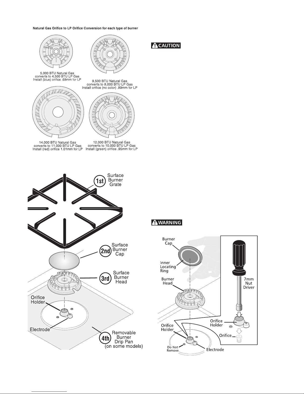
Figure 5
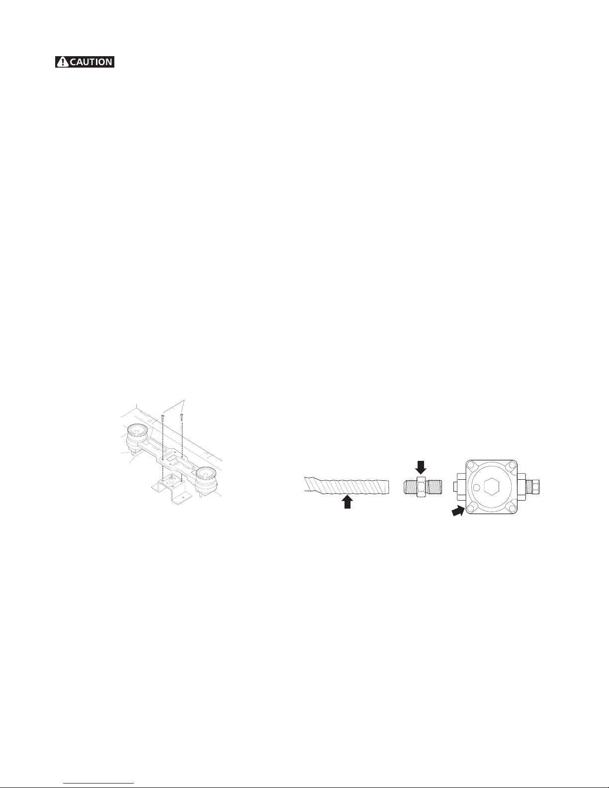
2. Convert Surface Burners for use with LP/
Propane Gas
Unlike the standard gas range, THIS
COOKTOP IS NOT REMOVABLE. Do not attempt to
remove this cooktop. Save the natural gas orifices
removed from the appliance for possible future conversions
to natural gas.
For all burner locations:
a. Remove the top grate and burner cap (See Figure 6).
b. Use your hand to remove the burner head.
c. Remove the four factory installed natural gas orifices
from the center of the orifice holders using a 7
mm nutdriver (See Figure 7). Remember to keep the
original Natural Gas Orifices for later conversion to
Natural Gas. Refer to page 1 under "IMPORTANT" to
identify their markings.
d. Replace the orifice in each of the four orifice holders
with the correct LP/Propane gas orifice (refer to the
LP Kit chart listed on page 1; also refer to Figures
4 and 5 for the correct LP orifice installation at
each of the four surface burner locations). Tighten
each orifice until snug. Use caution not to overtighten.
e. Replace the four burner heads (be sure burner head
mates correctly with each surface igniter) then replace
the burner caps and grates.
Use caution when replacing each burner
cap so the electrode is not damaged.
Figure 6
Figure 7
22
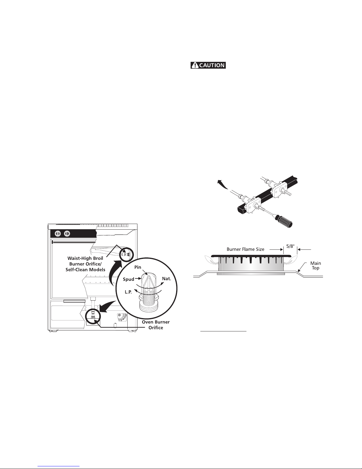
3. Convert Oven Burner Orifice for LP/Propane
Gas (16,000 BTU*)
a. Locate the oven burner spud (See Figure 8).
b. Using a 1/2" wrench, turn down the adjustable spud,
which injects gas into the oven burner, until snug
against the LP/Propane metering pin (approximately
2-1/2 turns). Do not over tighten.
4. Convert Waist-High Broiler Burner Orifice Flame
for LP/Propane Gas (13,500 BTU*) —Self-Cleaning
Models Only
a. Open the oven door.
b. Locate the broiler burner spud and turn down until
snug against the LP/Propane metering pin
(approximately 2-1/2 turns). Do not over tighten
(See Figure 8).
14" water column. When properly adjusted the manifold
water column pressure is 10" for LP/Propane gas or 4"
for Natural gas.
Do not use a flame to check for gas
leaks.
a. Disconnect the range and its individual shut-off valve
from the gas supply piping system during any
pressure testing of that system at test pressures
greater than 14" of water column pressure
(approximately 1/2" psig).
b. The appliance must be isolated from the gas supply
piping system by closing its individual manual shut-
off valve during any pressure testing of the gas
supply piping system at test pressures equal to or
less than 14" of water column pressure (approximately
1/2" psig).
5. Reconnect Gas and Electrical Supply to
Range.
Leak testing of the appliance shall be conducted according
to the Installation Instructions provided with the Range.
Figure 8
Checking Manifold Gas Pressure
To
Surface
Burner
Figure 9
Figure 10
Test to verify if “LOW” setting should be adjusted:
a. Push in and turn control to LITE until burner ignites.
b. Push in and quickly turn knob to LOWEST POSITION.
c. If burner goes out, reset control to OFF.
d. Remove the surface burner control knob.
If it should be necessary to check the manifold gas
pressure, remove the burner cap and connect a
manometer (water gauge) or other pressure device to the
top right front burner orifice. Using a rubber hose with
inside diameter of approximately 1/4," hold tubing down
tight over orifice. Turn burner valve on. For an accurate
pressure check, have at least two (2) other surface
burners burning. Be sure the gas supply (inlet) pressure
is at least one inch above specified range manifold
pressure. The gas supply pressure should never be over
e. Insert a thin-bladed screwdriver into the hollow valve
stem and engage the slotted screw inside. Flame
size can be increased or decreased with the turn of
the screw. Turn counterclockwise to increase flame
size. Turn clockwise to decrease flame size. (See
Figures 9 and 10).
Adjust flame until you can quickly turn knob from LITE to
LOWEST POSITION without extinguishing the flame.
Flame should be as small as possible without going out.
23
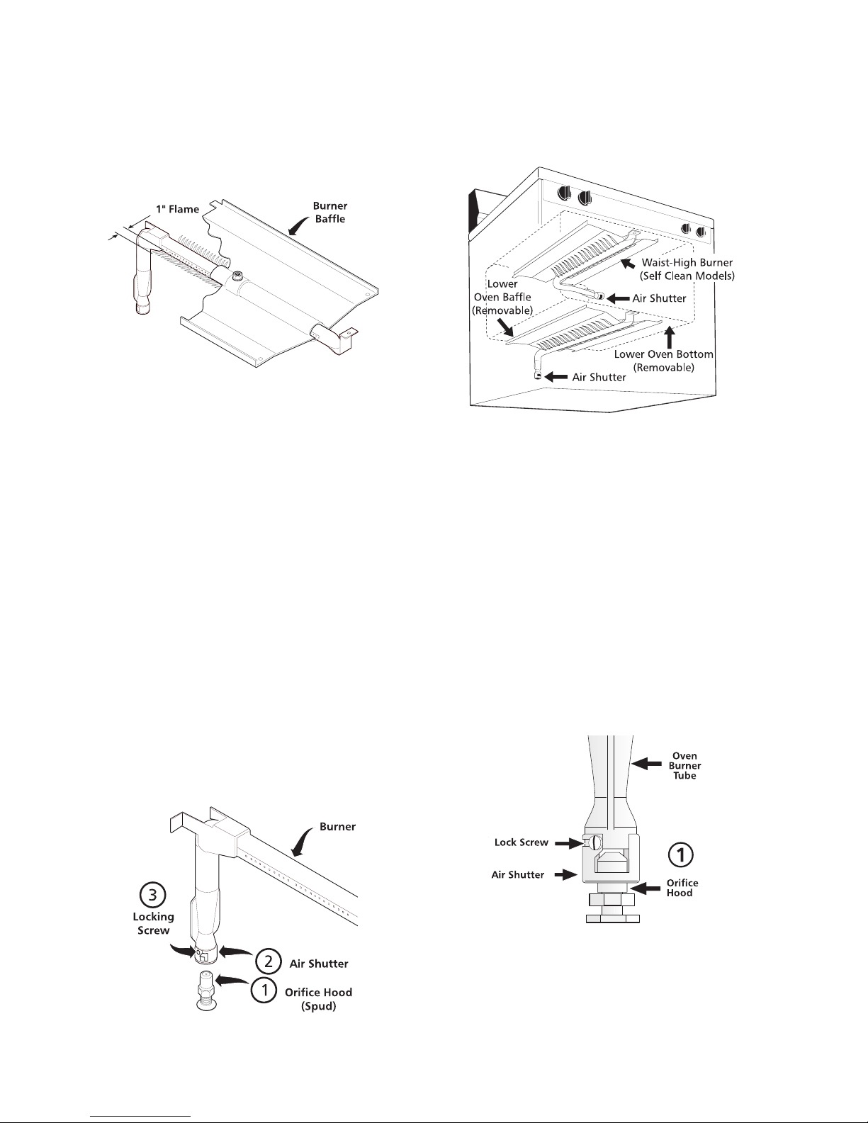
7. Air Shutter-Oven Burner
The air shutter for the oven burner may need adjustment,
especially if the unit has been converted for use with LP/
Propane gas. The approximate flame length of the oven
burner is 1 inch (distinct inner, blue flame) (See Figure
11).
Figure 11
To determine if the oven burner flame is proper:
a. To access the air shutter you must remove the
warmer drawer.
Retest the burner by repeating step “d” above. When the
burner flame is a distinct blue color burning steady, the
air shutter is adjusted correctly.
f. Replace burner baffle and oven bottom.
Figure 13
8. Air Shutter-Broil Burner
b. Remove the oven bottom by removing the screws at
rear of oven bottom. Lift up the rear of oven bottom
and slide toward back of range to disengage from
front of oven front frame.
c. Remove burner baffle by removing nut located on top
of baffle and two screws from front edge of oven front
frame. Lift baffle straight up and out of the oven.
d. Set the oven to bake at 350°F and observe the flame.
If the flame is yellow in color, increase air shutter
opening size. If the flame is a distinct blue color, but
lifting away from the burner; reduce the air shutter
opening size.
e. Turn off oven and allow to cool before adjusting air
shutter. To adjust loosen lock-screw (See Figure
12), reposition air shutter, and tighten lock-screw.
a. Observe the flame to determine if the broiler burner
flame is properly adjusted. It should be steady with
approximately 1" blue cones and no yellow or orange
flame tips (See Figure 13).
b. If adjustment to the air shutter is necessary, locate
the broiler burner air shutter (See figure 14), loosen
shutter lock screw, and adjust to obtain optimum
flame. This will normally be completely open for LP/
Propane gas. If the flame is yellow in color, increase
the air shutter opening size. If the flame is a distinct
blue, but lifting away from the burner, reduce the air
shutter opening size. Tighten the shutter set screw.
Figure 12
Figure 14
9. Replace Storage Drawer or Warmer Drawer
(instructions for warmer drawer if equipped):
24
a. Pull the bearing glides to the front of the chassis
glide (See Figure 15).
b. Align the glide on each side of the drawer with the
glide slots on the range.
c. Push the drawer into the range until levers “click”
(approximately 2”). Pull the drawer open again to
seat bearing glides into position. If you do not hear
the levers “click” or the bearing glides do not
feel seated remove the drawer and repeat
steps "a" through "c". This will minimize possible
damage to the bearing glides.
Figure 15
10. Installation of New LP/Propane Rating/Serial
Plate
c. Remove the four LP orifices using 7mm nutdriver and
replace with the four original factory installed natural
gas orifices at their original locations (See figure 4 for
locations).
d. Convert Oven Burner Orifice for Natural Gas by
loosening spud counter-clockwise (approximately
2-1/2 turns; See step 3).
e. Convert Waist-High Broiler Burner Orifice (Self-
Cleaning Models Only) for Natural Gas by loosening
spud counter-clockwise (approximately 2-1/2 turns).
(See step 4.)
f. Readjust “LOW” Setting for Surface Burner Valves
following instructions. (See step 6.)
g. Readjust Oven & Broil Burner Air Shutters. (See
steps 7 & 8.)
Record the model and serial number on the LP/Propane
Rating/Serial plate provided in this kit. The information
can be obtained from the existing Rating/Serial plate.
Place new plate as close as possible to the existing
Rating/Serial plate on range (See the recommended
locations shown in Figure 16).
Figure 16
CONVERSION TO NATURAL GAS
If it becomes necessary to convert the range back to
natural gas:
a. Disconnect gas and electrical supply from range.
b. Convert pressure regulator (See step 1), turn cap
over so the solid end of cap faces outward. Place the
hollow end of the cap into the loop end of the dust
protector.
25

36" GAS RANGE INSTALLATION INSTRUCTIONS
INSTALLATION AND SERVICE MUST BE PERFORMED
BY A QUALIFIED INSTALLER.
IMPORTANT: SAVE FOR LOCAL ELECTRICAL INSPECTOR'S USE.
READ AND SAVE THESE INSTRUCTIONS FOR FUTURE REFERENCE.
If the information in this manual is not followed exactly, a fire or explosion may result causing
property damage, personal injury or death.
FOR YOUR SAFETY:
— Do not store or use gasoline or other flammable vapors and liquids in the vicinity of this or any other appli-
ance.
— WHAT TO DO IF YOU SMELL GAS:
• Do not try to light any appliance.
• Do not touch any electrical switch; do not use any phone in your building.
• Immediately call your gas supplier from a neighbor's phone. Follow the gas supplier's instructions.
• If you cannot reach your gas supplier, call the fire department.
— Installation and service must be performed by a qualified installer, service agency or the gas supplier.
Dimensions and Clearance
Provide adequate clearance between range
and adjacent combustible surfaces.
TYPICAL CONTROL PANEL X. HEIGHT
HI Profile Control Panel 45 5/8" min.
LO Profile Control Panel 40 7/8" Min.
35 15/16”
X
45 3/8”
25 1/8”
36” +/- 1/8”
36”
Door open
Minimum to
wall on either
side of range
above 36”
height
36”
30” Minimum
2”
36 1/4”
Between Cabinets
Minimum to cabinets
on either side of
18”
range
0” Clearance at rear of
range below cooktop
Figure 1
26
Important Notes to the Installer
1. Read all instructions contained in these installation
instructions before installing the range.
2. Remove all packing material before connecting the
electrical supply to the appliance.
Standard, title 24CFR, part 3280 [Formerly the
Federal Standard for Mobile Home Construction
and Safety, title 24, HUD (part 280)] or when such
standard is not applicable, the Standard for Manufactured Home Installation 1982 (Manufactured
Home Sites, Communities and Set ups), ANSI
Z225.1
3. Observe all governing codes and ordinances.
4. Be sure to leave these instructions with the consumer.
Important Note to the Consumer
Keep these instructions with your Use and Care Guide
for future reference.
IMPORTANT SAFETY INSTRUCTIONS
Installation of this range must conform with local
codes, or in the absence of local codes, with the
National Fuel Gas Code ANSI Z223.1—latest edition.
This range has been design certified by American
Gas Association (A.G.A.). As with any appliance
using gas and generating heat, there are certain
safety precautions you should follow. You will find
them in the Use and Care Guide, read it carefully.
• Be sure your range is installed and grounded
properly by a qualified installer or service
technician.
• This range must be electrically grounded in
accordance with local codes, or in their absence, with the National Electrical Code ANSI/
NFPA No. 70—latest edition.
• The installation of appliances designed for manu-
factured (mobile) home installation must conform
with Manufactured Home Construction and Safety
• Before installing the range in area covered
with linoleum or any other synthetic floor
covering, make sure the floor covering can
withstand heat at least 90°F above room
temperature without shrinking, warping or
discoloring. Do not install the range over
carpeting unless you place an insulating pad
or sheet of ¼” thick plywood between the
range and carpeting.
• Make sure the wall coverings around the
range can withstand the heat generated by
the range.
• Do not obstruct the flow of combustion air at the
oven vent nor around the base or beneath the
lower front panel of the range. Avoid touching
the vent openings or nearby surfaces as they
may become hot. This range requires fresh air
for proper burner combustion.
• Do not store items of interest to children in the
cabinets above the range. Children could be
seriously burned climbing on the range to reach
items.
• To eliminate the need to reach over the sur-
face burners, cabinet storage space above the
burners should be avoided.
• Adjust surface burner flame size so it does
not extend beyond the edge of the cooking
utensil. Excessive flame is hazardous.
• Do not use the oven as a storage space. This
creates a potentially hazardous situation.
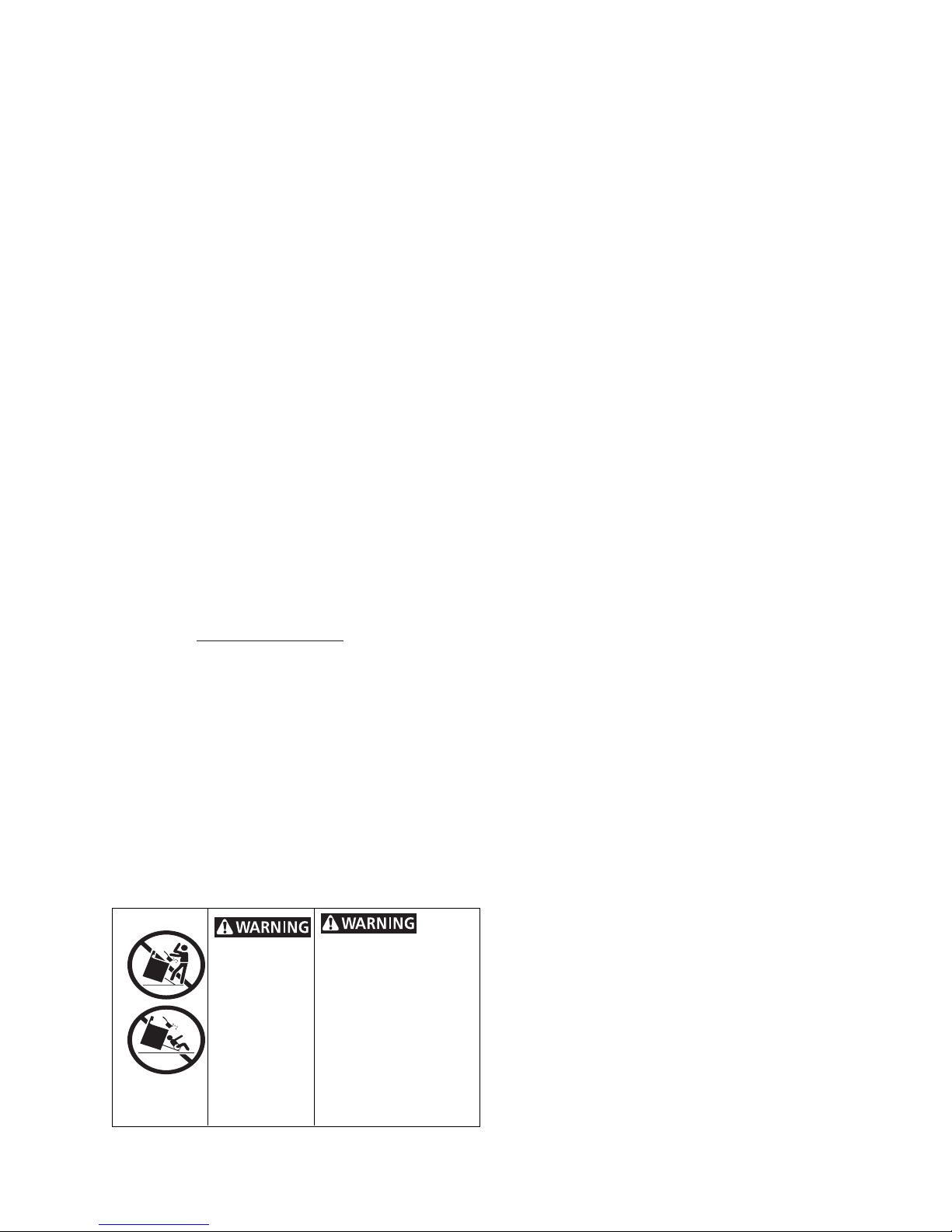
• All ranges
can tip.
• Injury to
persons
could result.
• Install antitip device
packed with
range.
To reduce the risk of
tipping of the range, the
range must be secured
by properly installed antitip bracket (s) provided
with the range. To check
if the bracket(s) is
installed properly, grasp
the top rear edge of the
range and carefully tilt it
forward to make sure the
range is anchored.
• Never use your range for warming or heating
the room. Prolonged use of the range without
adequate ventilation can be hazardous.
• Do not store or use gasoline or other flam-
mable vapors and liquids near this or any
other appliance. Explosions or fires could result.
• Remove broiler pan and other utensils and wipe
up excess spillage before self-cleaning the oven
(if equipped).
27
Do not make any attempt to oper-
ate the electric ignition oven during an electrical power failure. Resumption of electric power
when OVEN TEMP and OVEN SET controls are in
any position other than OFF will result in automatic
ignition of the oven or broiler burner.
For checking the regulator, the inlet pressure must
be at least 1" water column pressure greater than the
regulator manifold outlet setting. If the regulator is
set for 4" of manifold pressure, the inlet pressure
must be at least 5". If the regulator is set for 10", the
inlet pressure must be at least 11".
In case of a power outage, you can light the surface burners on your range with a match. Hold a
lighted match to the burner, then slowly turn the
knob to the LITE position. Use extreme caution
when lighting burners this way.
Surface burner in use when electrical power failure
occurs will continue to operate normally.
The oven burner and broil burner on your range
are lighted by electrical ignition. The oven and
broiler cannot be operated in the event of a
power failure.
1. Before Installing the Range
Remove shipping material
Remove all tape, shipping and packaging materials
and the oven rack packaging. Lift up cooktop and
remove the two shipping screws from the cooktop
burners (see figure 2).
Screws
The gas supply line into the range should be ½” or
¾” I.D. flexible metal appliance connector five feet
in length.
3. Seal the Openings
Seal any openings in the wall behind the range and
in the floor under the range when hookups are completed.
4. Connect the Range to Gas
Refer to Figures 4 to 7 for recommended connections.
A. Install a manual shut-off valve in the gas line in
an easily accessible location outside of the range.
Be sure you know how and where to shut-off the
gas supply to the range.
B.Install ½” flare union adaptor supplied with the
connector, to the ½” NPT internal thread on pressure regulator.
Gas Connection for Electric Ignition Models
Figure 2
2. Provide an Adequate Gas Supply
This range is designed to operate on natural gas at
4" of manifold pressure or on LP gas at 10" of
manifold pressure. It is shipped from the factory
set for natural gas. If it is to be used with LP gas,
adjustments must be made.
A convertible pressure regulator is connected in series with the manifold of the range and must remain
in series with the supply line regardless of whether
natural or LP gas is being used.
For proper operation, the maximum inlet pressure to the regulator must be no more than 14" of
water column (W.C.) pressure.
Flare Union Adaptor
Flexible Appliance
Connector
Pressure
Regulator
Figure 3
C.Because solid pipe restricts moving the range we
recommended use of A.G.A. design certified flexible metal appliance connector. Connect flexible
appliance to flare union.
D.Move range into approximate position and con-
nect flexible appliance connector to gas supply
line with proper flare union adaptor. The adaptor
supplied with the flexible connector must be used.
E. Check for leaks. Turn the gas supply on the
range and use a liquid leak detector at all joints
and connections to check for leaks in the system.
28
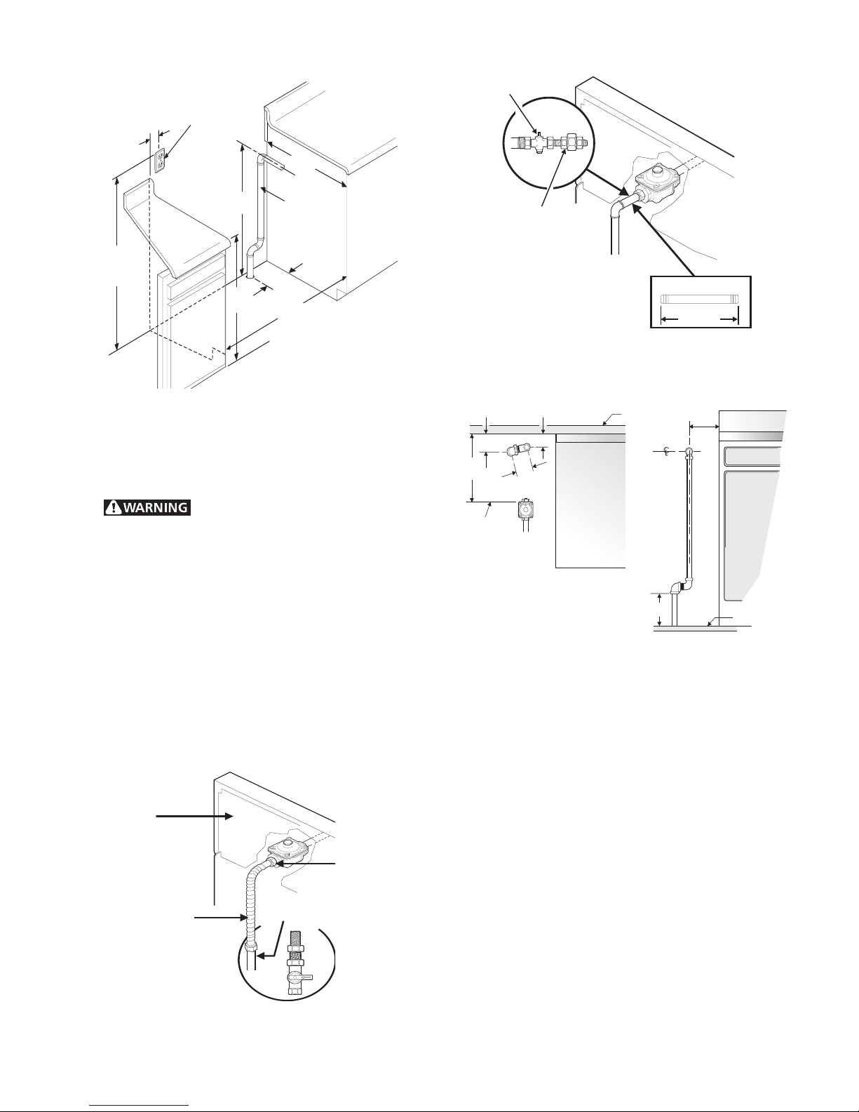
3"
3-Wire Polarized
120V. Outlet
32 7/8" ± ¼"
Gas Supply
Pipe
25"
Shut-Off Fitting
Union
Back of
Range
20"
or Lower
36"
Figure 4
Recommended locations for installing the electrical
outlet and pipe opening may be adjusted to meet
specific requirements.
Do not use a flame to check for
leaks from gas connections. Checking for leaks with
a flame may result in a fire or explosion.
Disconnect this range and its individual shutoff
valve from the gas supply piping system during any
pressure testing of that system at test pressures
greater than 14" of water column pressure (approx.
½” psig).
6 ¾"
36 ¼"
1 7/16"
11 ½ "
End of
Pressure
Regulator
Solid Pipe Hookup
¾
"
3 ¾"
TOP VIEW
Figure 6
Wall
Counter
To p
½" Nipple
Manifold
6"
FRONT VIEW
6 3/8"
2 5/8"
±¼"
Floor
Isolate the range from the gas supply piping
system by closing its individual manual shutoff
valve during any pressure testing of the gas supply
piping system at test pressures equal to or less than
14" of water column (approx. ½” psig).
Back of
Range
½" Close Nipple
Flexible
Connector
Flexible Connector Hookup
Recommended Shut-Off
Location
Figure 5
29
Solid Pipe Hookup Detail
Figure 7
5. LP/Propane Gas Conversion
A. Pressure Regulator Conversion
Do Not Remove the Pressure Regulator
Remove cap-screw and snap out the nylon gas
indicator by pushing it sideways. Turn the nylon
gas indicator for type gas (Natural or LP) and
snap it back in the cap-screw. Put cap-screw
back on gas regulator.

3.Lower main top and apply gas to check for proper flame
size. Flame should be steady with approximately ½”
blue inner cones and no yellow or orange tips.
L.P.
Figure 8
B. Surface Burner Valves Conversion
Air Shutter
Hood
NAT.
Cap Screw
Nat.
L.P.
Pin
Inner Cone Flame Length
½"
Figure 11
Proper Air Adjustment
If air shutter is adjusted so that too much air flows
into the burner, the flame will appear unsteady,
possibly not burning all the way around and will be
noisy (like a blow torch).
C. Readjust the “LOW” Setting Surface Burner
Valve
1. Turn control to LITE until burner ignites.
2. Quickly turn knob down to LOWEST SETTING.
Top Burner Adjustment
Figure 9
1. Lift cooktop to gain access to the surface
burner spuds.
2. With ½” wrench, turn spud down or clockwise
until snug (approximately 2 ½ turns). This restricts the flow of gas through spud to that allowed only by the hollow LP metering pin. Do
not overtighten.
Pin
Spud
Natural Gas
Increase Gas
Increase Flame
Size
(Pre-Set at Factory
for Natural Gas)
L.P. Gas
Decrease Gas
Decrease Flame
Size
Figure 10
3. If burner goes out, readjust valve as described
in “Adjust the LOW Setting Surface Burner
Valve” from Page .
D. Air Adjustment Shutter
Apply gas to the burner and adjust air shutter on
burner venturi tube to proper flame. For LP gas,
the air shutter is generally left completely open.
Air adjustment shutter
Figure 12
The air adjustment for each burner is located at
the open end of the venturi tube and sits on the
hood of the valve. The shutter is held in place by
friction fit.
30
 Loading...