


ELECTROLUX HOME PRODUCTS NORTH AMERICA
SERVICE MANUAL
NEXT GEN
30” ELECTRIC
FREESTANDING RANGES
5995361523
Whit e -W estin ghouse
December 2001
1
1111111

SAFE SERVICING PRACTICES - ALL APPLIANCES
To avoid personal injury and/or property damage, it is important that Safe Servicing
Practices be observed. The following are some limited examples of safe practices:
1. DO NOT attempt a product repair if you have any doubts as to your ability to
complete it in a safe and satisfactory manner.
2. Before servicing or moving an appliance:
• Remove the power cord from the electrical outlet, trip the circuit breaker to the
OFF position, or remove the fuse.
• Turn off the gas supply.
• Turn off the water supply.
3. Never interfere with the proper operation of any safety device.
4. USE ONLY REPLACEMENT PARTS CATALOGED FOR THIS APPLIANCE.
SUBSTITUTIONS MAY DEFEAT COMPLIANCE WITH SAFETY
STANDARDS SET FOR HOME APPLIANCES.
5. GROUNDING: The standard color coding for safety ground wires is GREEN, or
GREEN with YELLOW STRIPES. Ground leads are not to be used as current
carrying conductors. It is EXTREMELY important that the service technician
reestablish all safety grounds prior to completion of service. Failure to do so will
create a hazard.
6. Prior to returning the product to service, ensure that:
• All electrical connections are correct and secure
• All electrical leads are properly dressed and secured away from sharp edges,
high-temperature components, and moving parts
• All non-insulated electrical terminals, connectors, heaters, etc. are adequately
spaced away from all metal parts and panels
• All safety grounds (both internal and external) are correctly and securely
connected
• All panels are properly and securely reassembled
ATTENTION!!!
This service manual is intended for use by persons having electrical and mechanical training
and a level of knowledge of these subjects generally considered acceptable in the appliance
repair trade. Electrolux Home Products cannot be responsible, nor assume any liability, for
injury or damage of any kind arising from the use of this manual.
© 2001 White Consolidated Industries
2

TABLE OF CONTENTS
Safe servicing practices 2
Quick reference sheet 10
Maximum allowable surface temperatures 11
SECTION A - INSTALLATION 12 - 17
Clearances and dimensions 12
Important safety instructions 13
Tools you will need 13
Normal installation steps 13
Anti-tip bracket installation instructions 13
Electrical connection requirements 14
Grounding instructions 16
Model and serial number location 17
SECTION B - SURFACE ELEMENT CONTROL SYSTEM 18 - 23
Standard Infinite Switch 18 - 19
Troubleshooting 18 - 19
Element does not heat 18
Element does not cycle 19
Indicator light does not glow 19
Indicator light glows full brilliance with all switches off 19
Dual Infinite Switch 19 - 20
Troubleshooting 19 - 20
Both elements do not heat 20
Outer element doesn’t heat, but inner element does 20
Inner element doesn’t heat, but outer element does 20
Elements do not cycle 20
Indicator light does not glow 20
Indicator light glows full brilliance with all switches off 20
Top Element Electronic Control System 21 - 24
Components of the system 21
How it operates 22
Troubleshooting 22 - 24
F5 code 22
F6 code 23
F7 code 23
Blank display 23
Element not heating 23
Warm and Serve Zone 24
Troubleshooting 24
Element does not heat 24
Element does not cycle 25
Indicator light does not glow 25
Indicator light glows full brilliance with switch turned off 25
SECTION C - ELECTRONIC OVEN CONTROL SYSTEMS 26 - 66
The ES 100 Electronic Oven Control System 26 - 29
How to program the ES 100 26 - 27
To set the clock 26
To set the minute timer 26
To change the minute timer while it is in use 26
To cancel the minute timer before the set time has run out 26
To set the controls for baking 26
To change the oven temperature after baking has started 27
3

To broil 27
How the ES 100 operates 27
Bake 27
Broil 27
Calibration 28
The control cannot be calibrated 28
Troubleshooting 28 - 29
F1 code 28
F3 code 28
Control will not program 28
Control will not program 28
Blank Display 28
No heat 28
Bake element does not heat 28
Broil element does not heat 28
Sample schematic for ES100 control system 30
The ES 200 Electronic Oven Control System 31 - 36
How to program the ES 200 31 - 33
Temperature conversion 31
To change the temperature from °F to °C or from °C to °F 31
To set the clock 31
To set the minute timer 31
To change the minute timer while it is in use 32
To cancel the minute timer before the set time has run out 32
To set the controls for baking 32
To change the oven temperature after baking has started 32
To set control for continuous baking 32
To set control for oven lockout feature 32
To broil 32
To set the controls for a self-clean cycle 33
When the self-clean cycle is completed 33
Stopping or interrupting a self-cleaning cycle 33
How the ES 200 operates 33 - 34
Bake 33
Broil 34
Clean 34
Calibration 34
To change the calibration 34
Troubleshooting 34 - 36
F1 code 34
F3 code 34
F9 code 35
Control will not program 35
Blank display 35
Bake element does not heat 35
Broil element does not heat 35
Oven door does not lock when the oven is programmed for clean 35
Oven door locks but the oven does not heat 36
Lock motor runs continuously 36
Door latch is partly closed with door open 36
Sample schematic for ES200 control system 37
The ES 300 Electronic Oven Control System 38 - 45
How to program the ES 300 38 - 45
For a silent control panel 38
To change the temperature from °F to °C or from °C to °F 38
To set the clock 38
To set the minute timer 38
4

To change the minute timer while it is in use 39
To cancel the minute timer before the set time has run out 39
To set the controls for baking 39
To change the oven temperature after baking has started 39
To set control for continuous baking 39
To set control for oven lockout feature 39
To program the oven to begin baking immediately
and to shut off automatically 39
To program oven for a delayed start time
and to shut-off automatically 40
When the set bake time runs out 40
To change the oven temperature or bake
time after baking has started 40
Speed Bake™ 40
To set speed bake cooking system 41
To broil 41
To set the controls for a self-clean cycle 41
When the self-clean cycle is completed 42
Stopping or interrupting a self-cleaning cycle 42
How the ES 300 operates 42 - 45
Bake 42
Time bake 43
Speed bake 43
Broil 43
Clean 43
Calibration 43
To change the calibration 43
Troubleshooting 44 - 45
F1 code 44
F3 code 44
F9 code 44
Control will not program 44
Time bake does not operate 44
Blank display 44
Bake element does not heat 44
Broil element does not heat 45
Oven door does not lock when the oven is programmed for clean 45
Oven door locks but the oven does not heat 45
Lock motor runs continuously 45
Door latch is partly closed with door open 45
Fan in oven does not run when speed bake switch is turned on 45
Sample schematic for ES300 control system 46
The ES 400 Electronic Oven Control System 47 - 55
How to program the ES 400 47 - 52
Clock 47
To set the clock 47
Changing between 12 or 24 hour time of day display 47
Continuous bake or 12 hour energy saving 47
To set the control for continuous bake or 12 hour energy saving 47
Minute timer 48
To set the minute timer 48
To change the minute timer while it is in use 48
To cancel the minute timer before the set time has run out 48
Oven lockout feature 48
To activate the oven lockout 48
To reactivate oven operation 48
Temperature display - Fahrenheit or Celsius 48
5

To change the temperature from °F to °C or from °C to °F 48
Silent control operation 48
To change control from normal sound
operation to silent control operation 48
Preheat 49
48 To set preheat temperature 49
To change the preheat temperature while the oven is preheating 49
Bake 49
To set the bake temperature 49
To change the bake temperature 49
Timed bake 49
To program the oven to begin baking immediately
and to shut off automatically 49
Delay timed bake- cook time and stop time 50
To program oven for a delayed start time and
to shut-off automatically 50
To broil 50
To set the oven to broil 50
Convection bake 51
To set the convection bake feature 51
Convection roast 51
To set the convection roast feature 51
Self-clean cycle 51
To set the controls for the self-cleaning cycle
to start immediately and shut off automatically 51
When the self-clean cycle is completed 52
Stopping or interrupting a self-cleaning cycle 52
How the ES 400 operates 52 - 53
Preheat 52
Bake 52
Time bake 52
Convection bake 52
Convection roast 53
Broil 53
Clean 53
Calibration 53
To change the calibration 53
To adjust the oven temperature higher 53
To adjust the oven temperature lower 53
Troubleshooting 53 - 55
F1 code 53
F3 code 53
F9 code 54
Control will not program 54
Time bake does not operate 54
Convection bake and convection roast 54
Neither the fan motor or the assist element operates 54
If either the convection bake or roast operates
normal but the other does not 54
Fan motor does not operate 54
Assist element does not operate 54
Control does not operate in preheat 54
Blank Display 54
Bake element does not heat 54
Broil element does not heat 55
Oven door does not lock when the oven is programmed for clean 55
Lock motor runs continuously 55
6

Oven door locks but the oven does not heat 55
Door latch is partly closed with door open 55
Sample schematic for ES400 control system 56
The ES 450 Electronic Oven Control System 57 - 66
How to program the ES 450 57 - 62
Clock 57
To set the clock 57
Changing between 12 or 24 hour time of day display 57
Continuous bake or 12 hour energy saving 57
To set the control for continuous bake or 12 hour energy saving 57
Minute timer 58
To set the minute timer 58
To change the minute timer while it is in use 58
To cancel the minute timer before the set time has run out 58
Oven lockout feature 58
To activate the oven lockout 58
To reactivate oven operation 58
Temperature display - Fahrenheit or Celsius 58
To change the temperature from °F to °C or from °C to °F 58
Silent control operation 58
To change control from normal sound
operation to silent control operation 58
Preheat 59
58 To set preheat temperature 59
To change the preheat temperature while the oven is preheating 59
Bake 59
To set the bake temperature 59
To change the bake temperature 59
Timed bake 59
To program the oven to begin baking immediately
and to shut off automatically 59
Delay timed bake- cook time and stop time 60
To program oven for a delayed start time and
to shut-off automatically 60
To broil 60
To set the oven to broil 60
Convection bake 61
To set the convection bake feature 61
Setting food categories feature 61
To set the food categories feature 61
Self-clean cycle 61
To set the controls for the self-cleaning cycle
to start immediately and shut off automatically 62
When the self-clean cycle is completed 62
Stopping or interrupting a self-cleaning cycle 62
How the ES 450 operates 62 - 64
Preheat 62
Bake 62
Time bake 62
Convection bake 63
Fixed settings 63
Meats 63
Cakes 63
Breads 63
Broil 63
Clean 63
Calibration 63
7

To change the calibration 63
To adjust the oven temperature higher 63
To adjust the oven temperature lower 63
Troubleshooting 64 - 65
F1 code 64
F3 code 64
F9 code 64
Control will not program 64
Time bake does not operate 64
Convection bake 64
Neither the fan motor or the assist element operates 64
Fan motor does not operate 64
Assist element does not operate 64
Control does not operate in preheat 64
Blank Display 65
Bake element does not heat 65
Broil element does not heat 65
Oven door does not lock when the oven is programmed for clean 65
Lock motor runs continuously 65
Oven door locks but the oven does not heat 65
Door latch is partly closed with door open 65
Sample schematic for ES450 control system 66
Warmer drawer 67 - 68
To set the warmer drawer thermostat control 67
How the warmer drawer circuit works 67
Troubleshooting 67 - 68
Element does not heat 67
If the element heats during preheat, then stays off
until the temperature drops to about 130° F 68
If the element does not cycle off 68
If the warmer drawer is slow preheating 68
If the warmer drawer heats, but the indicator
light does not glow 68
SECTION D - DISASSEMBLY AND REPLACEMENT OF PARTS 69 - 86
Backguard 69 - 73
To remove the backguard back panel 69
To remove the infinite switches 69
To remove the knobs 69
To remove the potentiometers 69
To remove the user interface board 70
To remove the display window 70
To remove the top elements indicator light 71
To remove the electronic oven control 71
To remove the oven light switch 71
To remove the control panel 71
To remove the end caps 71
To remove the splasher panel 72
Main Top Area 73 - 76
To remove the main top with coil elements 73
To remove the main top on smooth top ranges 74
To remove the main top hinges 75
Top elements 75
To remove coil elements 75
To remove smooth top elements 75
To remove and replace terminal blocks for coil elements 76
To remove the lift and lock rods 76
8

To remove burner pan (coil element ranges only) 76
Oven door 76 - 78
To remove oven door seal 76
To remove oven door 77
Door hinge adjustment 77
Removal of the hinge opening cover 77
Door hinge removal 77
Oven door disassembly 77 - 78
Removing the upper door trim 77
Door handle 78
Outer door glass and trim 78
Center glass 78
Wool shield 78
Glass package and inner door liner 78
Components inside the oven 78 - 80
Bake element 78
Broil element 79
Fan blade (convection/speed bake models) 79
Convection assist element removal 79
Oven vent (coil element models) 79
Oven vent (smooth top models) 80
Removing the oven light cover (self-clean models) 80
Door latch removal (self-clean) 81
Door switch and rod removal (self-clean) 81
Components mounted to the back of the range 81 - 83
Removing the back cover 81
Removing lock motor assembly 81
Removing convection and speed bake motor assemblies 82
Removing oven sensor 82
Removing oven light socket 83
Removing mother board 83
Removing the bodyside panels 83
Storage drawer 84
Removing the storage drawer front panel 84
Removing inside drawer panel 84
Removing storage drawer glides 84
Removing the bottom heat shield 85
Removing bottom wool shield 85
Warmer drawer area 85
Removing the warmer drawer 85
Removing the warmer drawer side rail 85
Removing drawer rail from range frame 86
Removing warmer drawer low limit thermostat 86
Removing the warmer drawer element 86
9
Quick reference sheet
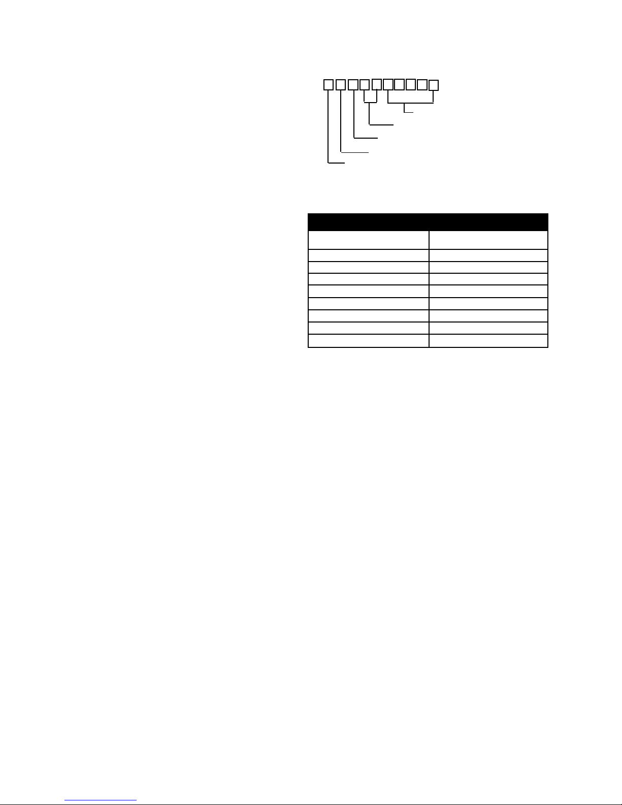
1. Serial number breakdown:
2. Oven sensor resistance chart:
N F 1 2 3 1 8 4 7 5
Incremented unit number
Production week
Last digit of production year
Product identification
Manufacturing Facility
RTD SCALE
Temperature Degrees F. Resistance (Ohms)
32 +/- 1.9 1000 +/- 4.0
75 +/- 2.5 1091 +/- 5.3
250 +/- 4.4 1453 +/- 8.9
350 +/- 5.4 1654 +/- 10.8
450 +/- 6.9 1852 +/- 13.5
550 +/- 8.2 2047 +/- 15.8
650 +/- 9.6 2237 +/- 18.5
900 +/- 13.6 2697 +/- 24.4
3. Element resistance
The wattage rating is stamped on the element. To determine the resistance divide the wattage by the voltage
rating on the element (either 250 or 120) to obtain the
amperage. Then divide the amperage into the voltage
rating to obtain the resistance. If for some reason you
cannot find the wattage rating, as a general rule most
element’s resistance will be between 15 and 45 Ohms.
10

Maximum allowable surface temperatures for gas & electric cooking products:
When Frigidaire tests side panels and doors for surface temperature, certain U.L. and/or A.G.A. guide lines
must be followed.
1. Product must be undamaged, correctly assembled and have the correct oven test temperature.
2. All surface temperatures are based on a room temperature of 77° F (25° C) and an oven set temperature of
400° F.
3. Oven must be cycling at 400° F for one hour before test is conducted.
4. Pyrometers (temperature testers) must be of high quality and properly adjusted.
5. An increase or decrease of 1° F in the room ambient temperature will allow a 1° F increase or decrease in
the maximum allowable surface temperature of the range.
Side Panel, Painted 152° F
Side Panel, Porcelain 160° F
Oven Door, Glass 172° F
Oven Door, Painted 152° F
Oven Door, Porcelain 160° F
Warmer Drawer, Painted 152° F
Warmer Drawer, Porcelain 160° F
Cooktop, No Temperature Limits Apply
Lower Console, No Temperature Limits Apply
Oven Vent Area, No Temperature Limits Apply
Knobs and Handles Skirt
Plastic* Metal Plastic* Metal
Conventional Gas & Electric 167 F 131 F 182 F 152 F
Self-Clean Gas at Clean Temperature 167 F 131 F 182 F 152 F
Self-Clean Gas at Clean Temperature 182 F 152 F 182 F 152 F
* Includes plastic with metal plating not more than 0.005" thick and metal with a plastic or vinyl covering not less
than 0.005" thick
11
SECTION A - INSTALLATION
INSTALLATION AND SERVICE MUST BE PERFORMED BY A QUALIFIED INSTALLER.
IMPORTANT: SAVE FOR LOCAL ELECTRICAL INSPECTOR'S USE.
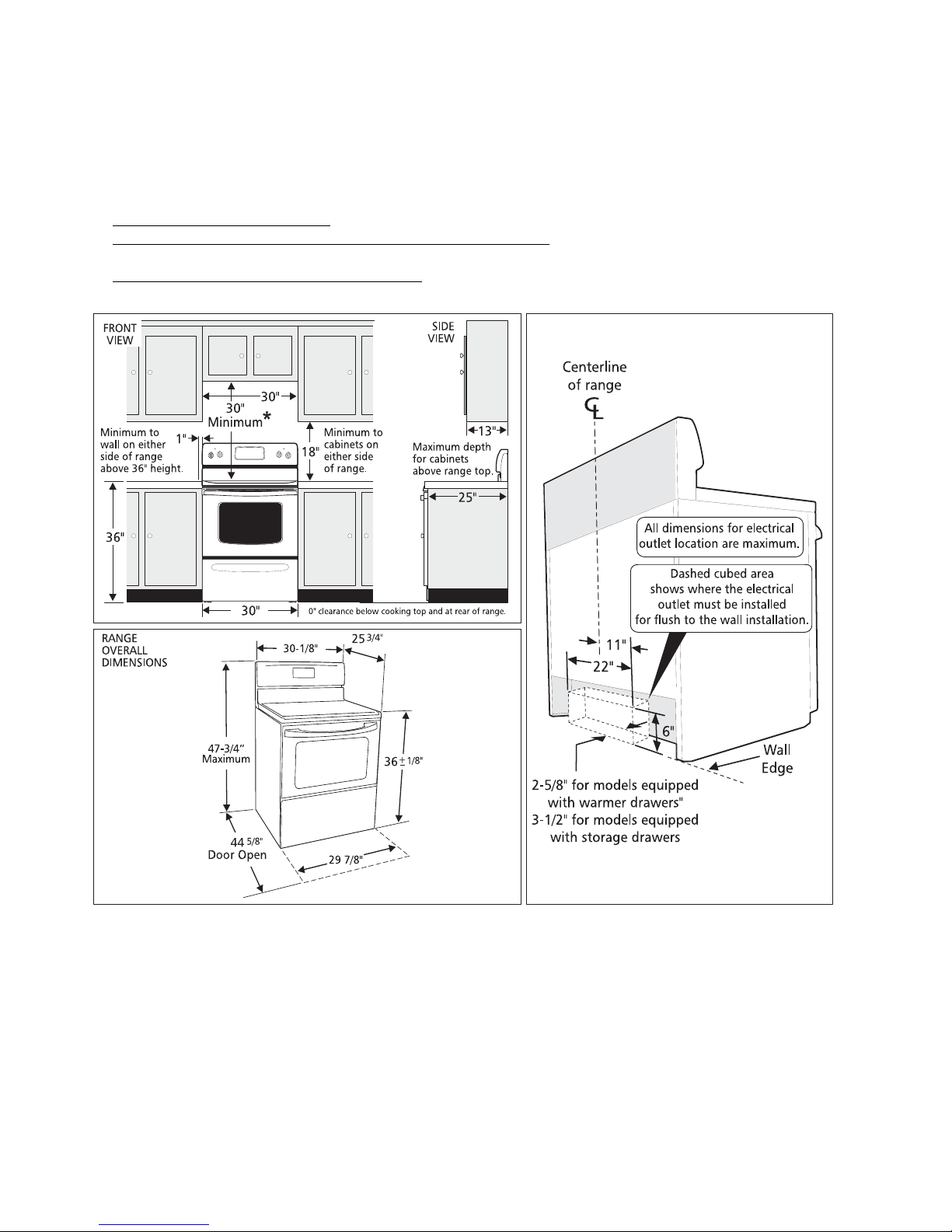
Clearances and Dimensions
1. Provide adequate clearances between the range and adjacent combustible surfaces.
2. Location—Check location where the range will be installed. Check for proper electrical supply, and
the stability of the floor.
3. Dimensions that are shown must be used. Given dimensions provide minimum clearance. Contact
surface must be solid and level.
*30" MINIMUM CLEARANCE BETWEEN THE TOP OF THE COOKING SURFACE AND THE BOTTOM OF AN
UNPROTECTED WOOD OR METAL CABINET; OR 24" MINIMUM WHEN BOTTOM OF WOOD OR METAL
CABINET IS PROTECTED BY NOT LESS THAN 1/4" FLAME RETARDANT MILLBOARD COVERED WITH NOT
LESS THAN NO. 28 MSG SHEET STEEL, 0.015" STAINLESS STEEL, 0.024" ALUMINUM OR 0.020" COPPER.
0" CLEARANCE IS THE MINIMUM FOR THE REAR OF THE RANGE. FOLLOW ALL DIMENSION REQUIREMENTS
PROVIDED ABOVE TO PREVENT PROPERTY DAMAGE, POTENTIAL FIRE HAZARD, AND INCORRECT
COUNTERTOP AND CABINET CUTS.
TO ELIMINATE THE RISK OF BURNS OR FIRE BY REACHING OVER HEATED SURFACE UNITS, CABINET
STORAGE SPACE LOCATED ABOVE THE SURFACE UNITS SHOULD BE AVOIDED. IF CABINET STORAGE
IS TO BE PROVIDED, THE RISK CAN BE REDUCED BY INSTALLING A RANGE HOOD THAT PROJECTS
HORIZONTALLY A MINIMUM OF 5" BEYOND THE BOTTOM OF THE CABINETS.
12
IMPORTANT SAFETY INSTRUCTIONS
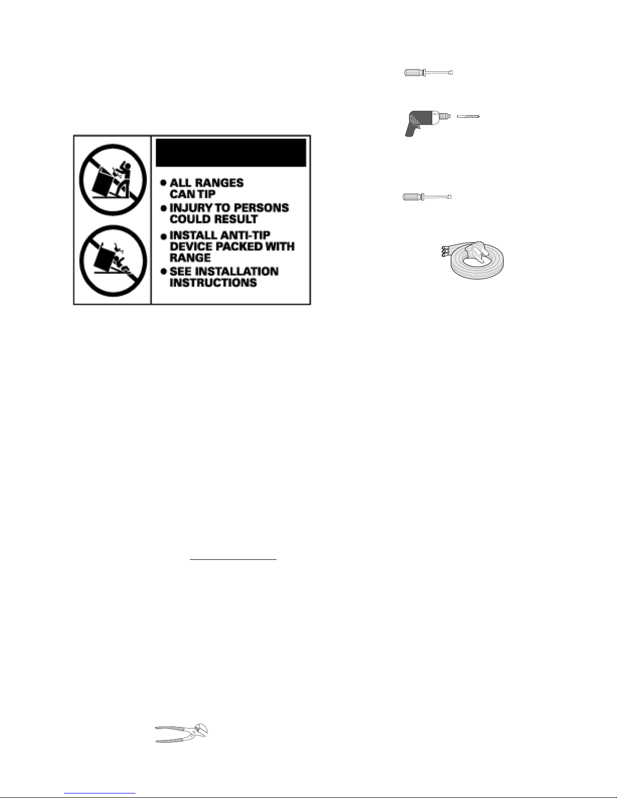
• 5/16" Nutdriver or Flat Head Screwdriver
WARNING: If the information in this manual is not
followed exactly, a fire or electrical shock may result
causing property damage, personal injury or death.
Important Notes to the Installer
1. Read all instructions contained in these installation
instructions before installing range.
2. Remove all packing material from the oven
compartments before connecting the gas and
electrical supply to the range.
3. Observe all governing codes and ordinances.
4. Be sure to leave these instructions with the
consumer.
• Electric Drill & 1/8" Diameter Drill Bit (MasonryDrill
Bit if installing in concrete)
For electrical supply connection:
• 1/4" & 3/8" Socket driver or Nutdriver
Additional Materials You Will Need
• Power Supply Cord or
• Copper Electrical Wiring & Metal Conduit (for hard
wiring)
Normal Installation Steps
1. Anti-Tip Bracket Installation Instructions
Important Safety Warning - To reduce the risk of
tipping of the range, the range must be secured to
the floor by properly installed anti-tip bracket and
screws packed with the range. Failure to install the
anti-tip bracket will allow the range to tip over if
excessive weight is placed on an open door or if a
child climbs upon it. Serious injury might result
from spilled hot liquids or from the range itself.
Important Note to the Consumer
Keep these instructions with your owner's guide for
future reference.
• As when using any appliance generating heat, there
are certain safety precautions you should follow.
These are listed in the
carefully.
• Be sure your range is installed and grounded properly
by a qualified installer or service technician.
• Make sure the wall coverings around the range can
withstand the heat generated by the range.
• To eliminate the need to reach over the surface
elements, cabinet storage space above the elements
should be avoided.
Before Starting - Tools You Will Need:
For leveling legs and Anti-Tip Bracket:
• Adjustable wrench or channel lock pliers
Use & Care Manual, read it
13
If range is ever moved to a different location, the
anti-tip brackets must also be moved and installed
with the range.
Instructions are provided for installation in wood or
cement fastened to either the floor or wall. When
installed to the wall, make sure that screws
completely penetrate dry wall and are secured in
wood or metal. When fastening to the floor or wall,
be sure that screws do not penetrate electrical
wiring or plumbing.
A. Locate the Bracket Using the Template -(Bracket
may be located on either the left or right side of the
range. Use the information below to locate the
bracket if template is not available). Mark the floor
or wall where left or right side of the range will be
located. If rear of range is against the wall or no
further than 1-1/4" from wall when installed, you may
use the wall or floor mount method. If molding is
installed and does not allow the bracket to fit flush
against the wall, remove molding or mount bracket
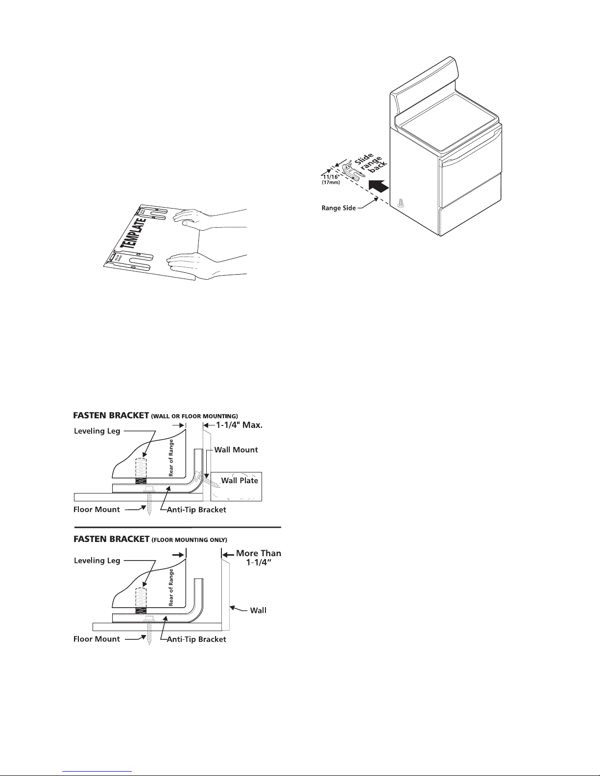
to the floor. For wall mount, locate the bracket by
placing the back edge of the template against the
rear wall and the side edge of template on the mark
made referencing the side of the range. Place
bracket on top of template and mark location of the
screw holes in wall. If rear of range is further than 11/4" from the wall when installed, attach bracket to
the floor. For floor mount, locate the bracket by
placing back edge of the template where the rear of
the range will be located. Mark the location of the
screw holes shown in template.
B. Drill Pilot Holes and Fasten Bracket - Drill a 1/8"
pilot hole where screws are to be located. If bracket
is to be mounted to the wall, drill pilot hole at an
approximate 20° downward angle. If bracket is to be
mounted to masonry or ceramic floors, drill a 5/32"
pilot hole 1-3/4" deep. The screws provided may be
used in wood or concrete material. Use a 5/16" nutdriver or flat head screwdriver to secure the bracket
in place.
the bottom of the range and the leveling leg to allow
room for the bracket. Use a spirit level to check your
adjustments. Slide range back into position. Visually
check that rear leveling leg is inserted into and fully
secured by the Anti-Tip Bracket by removing lower
panel or storage drawer. For models with a warmer
drawer or broiler compartment, grasp the top rear
edge of the range and carefully attempt to tilt it
forward.
2. Electrical Connection Requirements
This appliance must be properly installed and grounded
by a qualified technician in accordance with the National
Electrical Code ANSI/NFPA No. 70--latest edition--and
local electrical code requirements.
C. Level and Position Range - Level range by
adjusting the (4) leveling legs with a wrench. Note:
A minimum clearance of 1/8" is required between
This appliance may be connected by means of permanent
"Hard Wiring" or "Power Supply Cord Kit."
When hard wiring, do not leave excess wire in range
compartment. Excess wire in the range compartment
may not allow the access cover to be replaced properly,
and could create a potential electrical hazard if wires
become pinched. Connect only as instructed under
"WIRING INSTRUCTIONS" in section 4A or 4B. When
using flexible conduit or range cable use flex connector
or range cable strain relief.
NOTE: Only use copper wire in connection to terminal
block.
2A. Models with Factory Connected Power Supply
Cord
NOTE: Some models may be equipped with a factory
connected three (3) conductor power supply cord.
14
Mobile home installations, new branch circuit
installations (1996NEC) or areas where local codes do
not permit grounding through neutral require a four (4)
conductor power supply cord kit rated at 125/250 volts
minimum and marked for use with ranges. See Range
Connection Opening Size Chart for cord kit ampere
rating information. Terminals on end of wires must be
either closed loop or open-end spade lugs with upturned
ends.
Range Connection Opening Size Chart
Supply Cord Kit ampere rating information. See
serial plate on Range for kilowatt rating data.
See Serial Plate on
Range for KW Rating
120/240 Volts
120/208 Volts
Cord Kit
Ampere
Rating
Diameter (in.) of Range
Connection Opening
Cord Kit
Permanent
Wiring
2B. Models Requiring Power Supply Cord Kit
RISK OF FIRE OR ELECTRICAL SHOCK MAY OCCUR
IF AN INCORRECT SIZE RANGE CORD KIT IS USED,
THE INSTALLATION INSTRUCTIONS ARE NOT
FOLLOWED OR STRAIN RELIEF BRACKET IS
DISCARDED.
This appliance may be connected by means of a power
supply cord. Only a power supply cord kit rated at 125/
250 volts minimum, and marked for use with ranges
shall be used. See chart on page 3 for cord kit ampere
rating information. Cord must have either three (3) or four
(4) conductors. Terminals on end of wires must be either
closed loop or open-end spade lugs with upturned ends.
Cord must have strain relief clamp.
See section 4A for 3-wire or section 4B for 4-wire
connection.
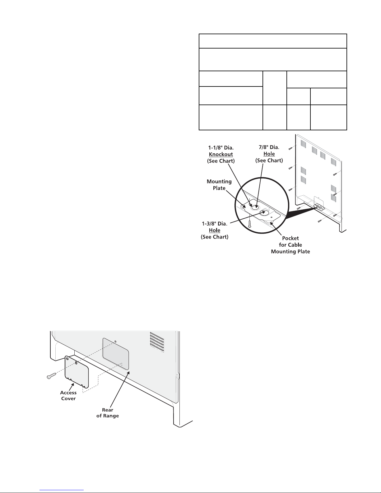
3. Electrical Connection to Range
The rear access cover must be removed. To remove,
loosen center screw (one screw) and remove access
cover. The terminal block will then be accessible.
8.8-16.5 KW/7.9-12.5 KW
16.6-22.5 KW/12.6-18.5 KW
40/50
Amp
1-3/8 in.
1-3/8 in.
1-1/8 in.
1-3/8 in.
NOTE: Range is shipped from factory with 1-3/8" dia.
hole as shown. To use either 7/8" dia. hole or 1-1/8" dia.
knockouts:
Access Cover
If a different diameter hole is required, please
follow the steps below:
1. Using a 1/4" socket driver, remove eight (8) screws
from Rear Wall Shield to release from the unit (as
shown). Save the screws for step 7 below.
2. Again using the 1/4" socket driver, remove one (1)
blunt point screw used to secure the Cable Mounting
Plate to the Rear Wall Shield. Save the screw for
step 6.
3. Remove the Cable Mounting Plate from the Rear
Wall Shield by sliding the plate out of the pockets.
4. If a 1-1/8" dia. hole is required, "punch-out" the
knockout.
5. Rotate the plate 180 degrees so that the desired
hole is placed on top of the opening located on the
bottom flange of the Rear Wall Shield.
15

6. Slide the Cable Mounting Plate into the Rear Wall
Shield. Re-secure using the blunt point screw
removed from step #2 above.
7. Reassemble the Rear Wall Shield to the unit using
eight (8) screws removed from step #1 above.
4A. Wiring Instructions (3-Wire Connection)
1. Remove the three (3) loose nuts on the terminal
block using a 3/8" nut driver or socket.
NOTE: Do not loosen the nuts which secure the
factory installed range wiring to the terminal block.
Electrical failure or loss of electrical connection may
occur if nuts are loosened.
GROUNDING INSTRUCTIONS:
A ground strap is installed on this range which connects
the center terminal of the terminal block (neutral) to the
chassis. The ground strap is shown in the 3-wire
connection picture below and is connected to the range
by the center, lowest screw. The ground link must not be
removed unless national or local codes do not permit
use of ground strap.
NOTE: If the ground strap is removed for any reason, a
separate ground wire must be connected to the separate
ground screw attached to the range chassis and to an
adequate ground source.
4B. Wiring Instructions (4-Wire Connection)
2. Using the nuts removed in step 1, connect the cable
or copper power supply cord to the three (3) studs on
the terminal block, as local codes require. The
neutral (white) wire or center wire must be connected
to the center terminal.
3. Make sure all nuts are tightened securely.
4. Replace the rear access cover
If connecting to a 4-wire electrical system (new branchcircuit or mobile home requires 4 wire connection):
1. Remove the three (3) loose nuts on the terminal
block using a 3/8" nut driver or socket. From the
center stud on the terminal block, remove the
second nut and the copper ground strap. Replace
the nut that held the ground strap to the terminal
block.
NOTE: Do not loosen the second nut on line 1 or line
2 which secure the factory installed range wiring to
the terminal block. Electrical failure or loss of electrical
connection may occur if nuts are loosened.
2. Remove the ground screw to release the copper
ground strap from the appliance.
3. Discard the ground strap. Connect the ground wire
(green) of the copper power supply cord to the frame
of the appliance with the ground screw,using the
same hole in the frame where the ground strap was
removed.
4. Using the nuts removed in step 1, connect the neutral
(white) wire of the copper power supply cord to the
center silver colored stud on the terminal block.
5. Connect the final two (2) wires to the outer studs on
the terminal block.
6. Make sure all nuts are tightened securely.
7. Replace the rear access cover.
16

Before You Call for Service
Read the "Before You Call" and operating instruction
sections in your
Use & Care Manual. It may save you
time and expense. The list includes common occurrences
that are not the result of defective workmanship or
materials in this appliance.
Model and Serial Number Location
The serial plate is located on the right-hand surface of the
oven front frame at the storage or warmer drawer; or the
lower panel area.
Refer to the warranty in your
Use & Care Manual for our
toll-free service number and address. Please call or write
if you have inquiries about your range product and/or
need to order parts.
When ordering parts for or making inquires about your
range, always be sure to include the model and serial
numbers and a lot number or letter from the serial plate
on your range.
Your serial plate also tells you the Kilowatt rating (power
requirements) and Voltage ratings
Care, Cleaning and Maintenance
Refer to the Use & Care Manual for cleaning instructions.
If removing the range is necessary for cleaning or
maintenance, disconnect the electrical power supply. If
the electrical supply is inaccessible, lift the unit slightly
at the front and pull out away from the wall. Pull only as
far as necessary to disconnect the electrical supply.
Finish removing the unit for servicing and cleaning.
Reinstall in reverse order making sure to level the range
and check electrical connections. See pages 13 and 14
for proper anchoring instructions.
17
SECTION B - SURFACE ELEMENT
CONTROL SYSTEMS
Three types of surface elements control systems are
covered in this manual.
1. Standard infinite switch.
2. Dual infinite switch.
3. Electronic top element system. (ESEC 5)
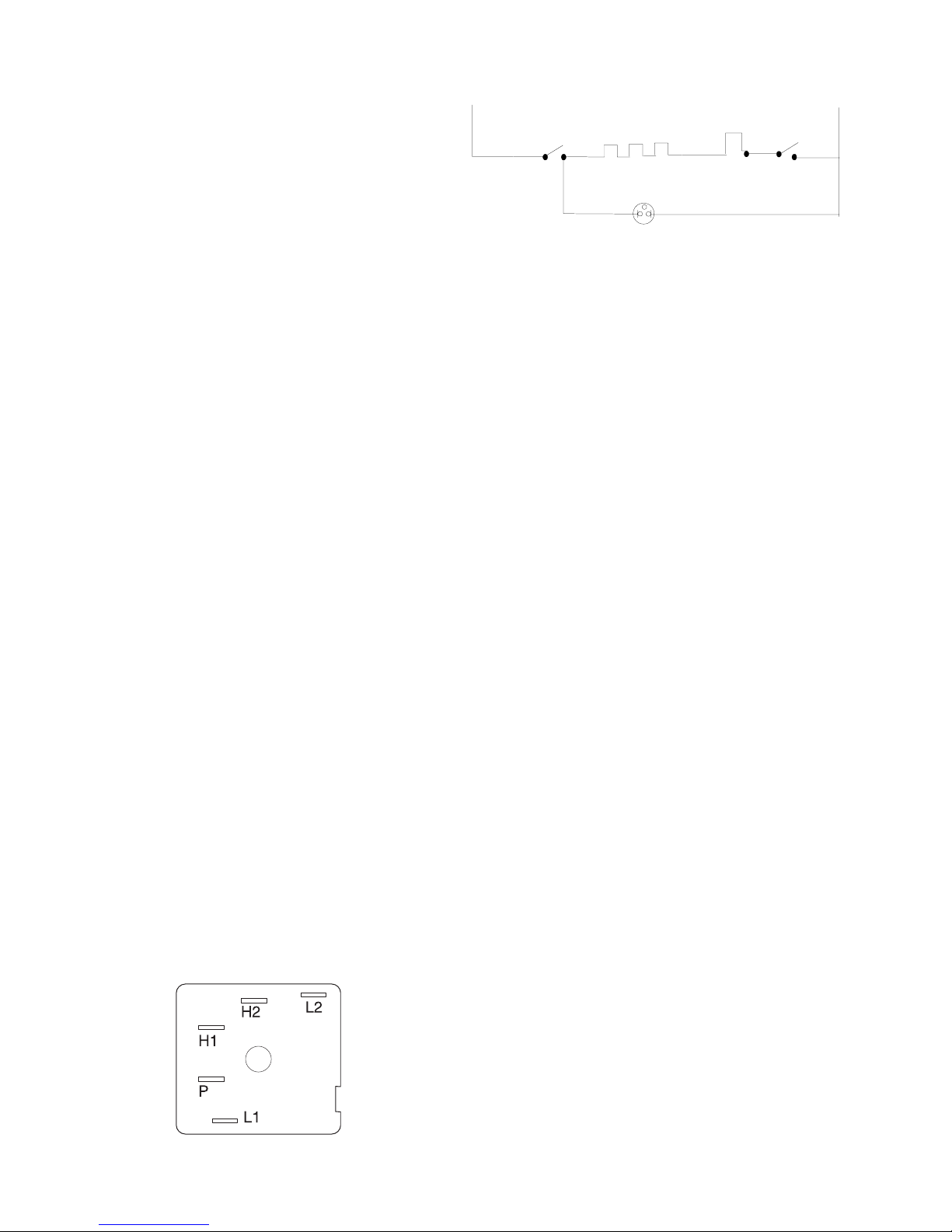
Standard infinite switch:
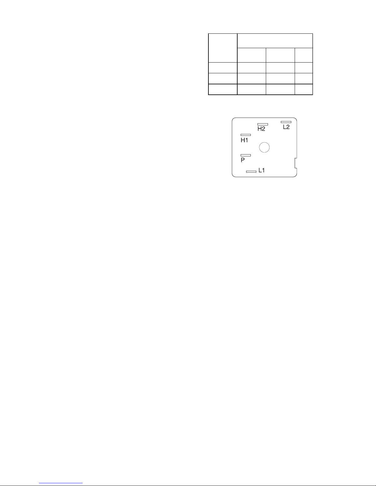
The surface elements and standard infinite switches provide an infinite choice of heat settings for cooking. Controls are safety type and must be pushed in before turning. All surface controls are marked on the control panel
for their respective heating element. Power is supplied
to the surface elements through the infinite switch contacts L1-H1 and L2-H2. During actual surface element
operation, if the control is set to the high position contacts L2-H2 are lock closed providing continuous power
to the element. In all other setting contacts L2-H2 will
cycle to maintain the correct heat setting. Contacts L1P provide power to the surface element indicator light.
Dial Position
Contacts
OFF LO-MED HI
L1 - P O X X
L1 - H1 O X X
L2 - H2 O X - C X
Element does not heat:
Checking the system with a Voltmeter, if the element
does not heat up.
Troubleshooting:
There are four ways a surface control system with a
standard infinite switch can fail.
1. The element does not heat.
2. The switch does not cycle the element off and
on when set to a position other than high.
3. The element operates correctly, but the
indicator light does not glow.
4. Indicator light glows with all infinite switches
in the off position.
NOTE: If the indicator light glows very dimly
with all the switches in the off position. This
problem is caused by a capacitive feed over in
the wiring and can be corrected by connecting
a 100,000 Ohm 1/4 watt resistor in parallel with
the light.
Continuity tests can be performed on the infinite switch
contacts. All tests should be performed with power to
the range disconnected, and wiring removed from the
switch. Set an ohmmeter on R X 1K scale and check
the contacts in the following chart and switch terminal
diagram.
1. Remove the back of the control panel to
expose the switch terminals.
2. With a Voltmeter set for AC on a scale higher
than 240 Volts measure the voltage drop
between terminals L1 and L2. If the meter
reads zero the wiring between the main
terminal block on the range and the switch is
open. If the meter reads line to line voltage
(around 240 VAC) go to step 3.
3. With the switch turned to the high position
measure the voltage drop between terminals
H1 and H2. If the meter reads zero the switch
is defective. If the meter reads line to line
voltage the switch is good. If the range has
standard elements go to step 4. If the range
has a glass smooth go to step 5.
4. Remove the element and measure the
voltage drop between terminals of the terminal
block. If the meter reads zero the terminal
block or the wiring between the switch and the
terminal block is open. If the meter reads line
to line voltage the element is defective.
NOTE: Always inspect the terminal block for
burnt spots that can cause poor connection.
5. Raise the top and locate the two terminals on
the element that the wires from H1 and H2 are
on. Measure the voltage drop between the two
terminals. If the meter reads zero the wires
18
between the switch and the element are open.
If the meter reads line to line voltage the
element is defective.
Element does not cycle:
If the element does not cycle when the switch is set in a
position other than high the switch is defective.
Indicator light does not glow:
If indicator light does not glow when the switch is turned
on, remove the back panel of the backguard, turn the
switch on, and measure the voltage drop between terminals P and L2. If the meter reads zero the switch is
defective. If the meter reads line to line voltage (around
240 VAC) the light or the wiring to the light is defective.
Indicator light glows full brilliance with all top
element switches off:
If indicator light glows full brilliance with all top element
switches off, one or more of the switches are defective.
Disconnect electrical power from the range, and remove
the back panel of the backguard. Disconnect the wire
from the P terminal on all switches but one switch. Reconnect power. If the indicator light glows with the switch
in the off position, the switch is defective. If the indicator
light does not glow, the switch is good. Check each
switch by disconnecting the wires from all the other P
terminals but the switch you are testing.
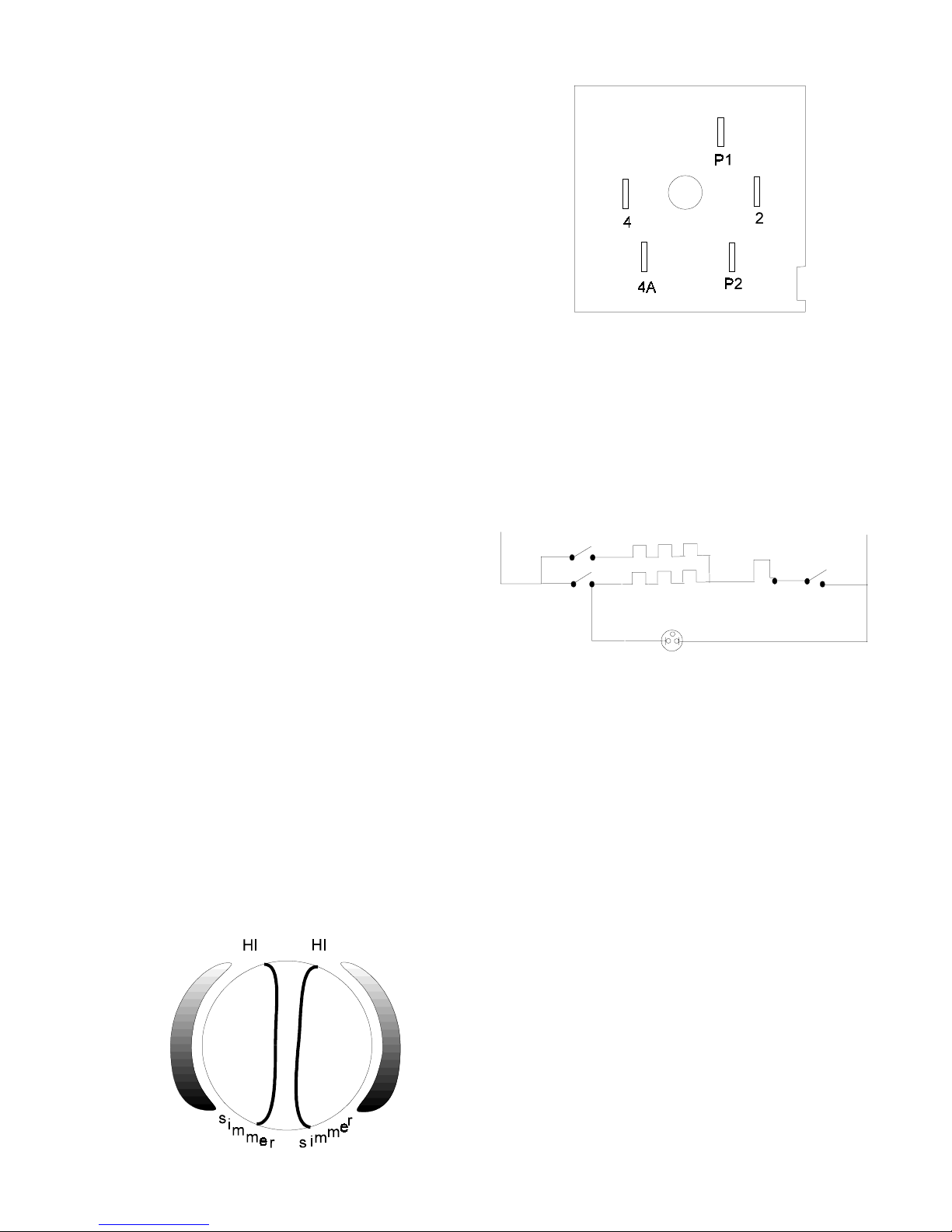
Dual infinite switch:
providing power to both elements. When the knob is
turned counterclockwise, less than 180 degrees, contacts P2 to 4 and P1 to 2 close providing power to the
inner element. During actual surface element operation, if the control is set to the high position contacts P1
to 2 are locked closed providing continuous power to
the element. In all other settings contacts P1 to 2 will
cycle to maintain the correct heat setting. Contact 4 to
L2 provides power to the surface element indicator light.
L1
P2
OUTER COIL
4A
4
INNER COIL
TEMPERATURE
LIMIT SWITCH
2
1A
2A
L2
P1
SURFACE INDICATOR
The dual infinite switch is used to control the expandable and bridge elements on electric smooth top ranges.
The dual infinite switches provide an infinite choice of
heat settings for cooking, and two selection of element
sizes. Controls are safety type and must be pushed in
before turning. All surface controls are marked on the
control panel for their respective heating element.
When the knob is turned clockwise, less than 180 degrees, contacts P2 to 4, P2 to 4A, and P1 to 2 closes
SMALL
ELEMENT
LARGE
ELEMENT
Troubleshooting:
There are six ways a surface control system with a dual
infinite switch can fail.
1. Both elements do not heat.
2. The outer element does not heat.
3. The inner element does not heat.
4. The switch does not cycle the element off and
on when set to a position other than high.
5. The element operates correctly, but the
indicator light does not glow.
6. Indicator light glows with all the infinite switches
in the off position.
NOTE: If the indicator light glows very dimly
with all the switches in the off position. This
problem is caused by a capacitive feed over in
the wiring and can be corrected by connecting
a 100,000 Ohm 1/4 watt resistor in parallel with
the light.
19
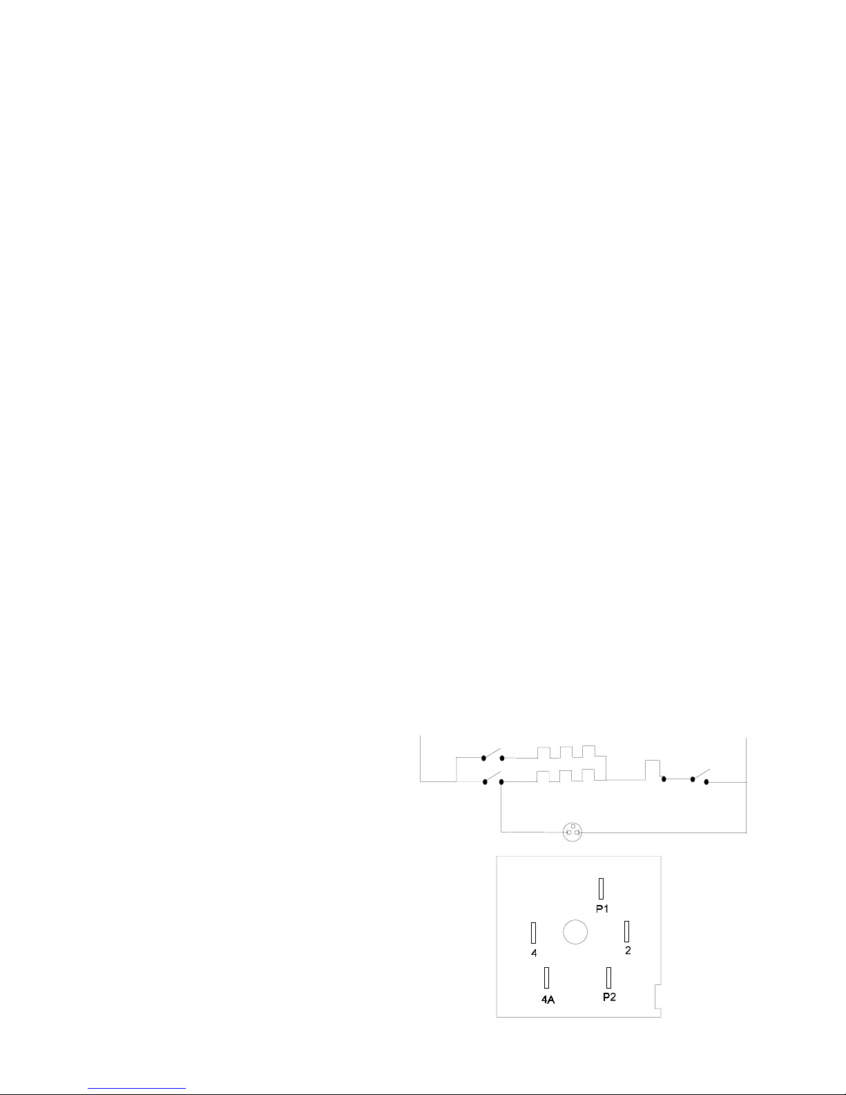
Both elements do not heat:
Checking the system with a Voltmeter, if the elements
do not heat up:
1. Remove the back panel of the backguard to
expose the switch terminals.
2. With a Voltmeter set for AC and a scale higher
than 240 Volts measure the voltage drop
between terminals P1 and P2. If the meter
reads zero the wiring between the main
terminal block on the range and the switch is
open. If the meter reads line to line voltage
(around 240 VAC) go to step 3.
2. With the switch turned clockwise to the high
position measure the voltage drop between
terminals 4 and 2. If the meter reads zero
the switch is defective. If the meter reads line
to line voltage, go to step 3.
3. Raise the top and locate the two terminals on
the element where the wires from terminals 4
and 2 are connected. Measure the voltage drop
between these two terminals. If the meter reads
zero the wires between the switch and the
element are open. If the meter reads line to
line voltage the element is defective.
Elements do not cycle:
3. With the switch turned clockwise to the HI
position, measure the voltage drop between
terminals 4 and 2. If the meter reads zero the
switch is defective. If the meter reads line to
line voltage measure the voltage drop between
terminals 4A and 2. If the meter reads line to
line voltage the switch is good. Go to step 4.
4. Raise the top and locate the two terminals on
the element with the wires from terminals 4
and 2 are connected. Measure the voltage drop
between these two terminals. If the meter reads
zero the wires between the switch and the
element are open. If the meter reads line to
line voltage the element is defective.
Outer element doesn’t heat, but inner element does:
Checking the system with a Voltmeter, if the outer element does not heat, but the inner element does:
1. Remove the back panel of the backguard to
expose the switch terminals.
2. With the switch turned clockwise to the high
position measure the voltage drop between
terminals 4A and 2. If the meter reads zero
the switch is defective. If the meter reads line
to line voltage, go to step 3.
3. Raise the top and locate the two terminals on
the element where the wires from terminals 4A
and 2 are connected. Measure the voltage drop
between these two terminals. If the meter reads
zero the wires between the switch and the
element are open. If the meter reads line to
line voltage the element is defective.
If the elements do not cycle when the switch is set in a
position other than high the switch is defective.
Indicator light does not glow:
If indicator light does not glow when the switch is turned
on, remove the back panel of the backguard, turn the
switch on, and measure the voltage drop between terminals 4 and L2. If the meter reads zero the switch is
defective. If the meter reads line to line voltage (around
240VAC) the light or the wiring to the light is defective.
Indicator light glows full brilliance with all top element switches off:
If indicator light glows full brilliance with all top element
switches off, one or more of switches are defective. Disconnect electrical power from the range, and remove the
back panel of the backguard. Disconnect the wire from
terminal 4 on the switches from all but one switch. Reconnect power. If the indicator light glows with the switch
in the off position the switch is defective. If the indicator
light does not glow the switch is good. Check each dual
infinite switch by disconnecting the wires from all the
other 4 terminals but the switch you are testing.
L1
P2
OUTER COIL
4A
4
INNER COIL
TEMPERATURE
LIMIT SWITCH
2
1A
2A
L2
P1
SURFACE INDICATOR
Inner element doesn’t heat, but outer element does:
Checking the system with a Voltmeter, if the inner element does not heat, but the outer element does:
1. Remove the back panel of the backguard to
expose the switch terminals.
20
Top Element Electronic Control System:
Some electric range models are equipped with electronic
top element controls, these controls are more accurate
and allow for a lower simmer temperature than the
conventional infinite switches.
CAUTION: ON MODELS WITH ELECTRONIC TOP
ELEMENT CONTROLS, LINE 1 IS CONNECTED TO
THE TOP ELEMENTS WHENEVER ELECTRICAL
POWER IS APPLIED TO THE RANGE.
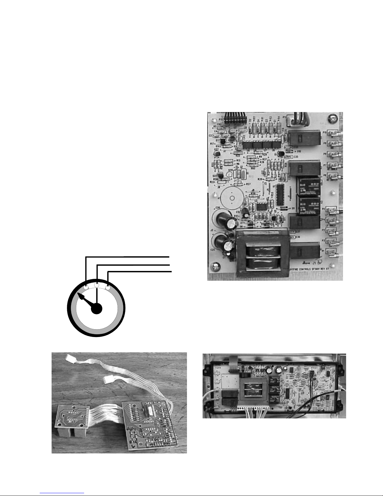
Components of the system:
The top element electronic control system (engineering
named ESEC 5) is made up of five components;
Potentiometers, User Interface Boards, Mother Board,
Electronic Oven Control, and Top Elements.
1. Four potentiometers (variable resistors) - one for each
top element, that the user changes the resistance of
when they turn the knob. Because of the different types
of elements two different potentiometers are used. A
potentiometer with a resistance of 20,000 Ohms is used
with the single element, and a potentiometer with a
resistance of 10,000 Ohms is used with the dual and
bridge elements. The potentiometers are identified by
the color of their base. The 20,000 Ohm potentiometer
has a gray base, the 10,000 potentiometer has a black
base.
the range, with four displays, one for each element that
shows the setting of the control. These work as interfaces
between potentiometers and the mother board.
3. One mother board - main circuit board that has a
transformer to provide low voltage for the system, a
microprocessor that controls and communicates with
the other components of the system, and relays that
control line to line voltage to the top elements.
Potentiometer
2. Two user interface boards (UIB) - one for each side of
User Interface Board
Mother Board
4. A section of the electronic oven control (EOC) communicates with the mother board to allow a lockout
feature on the EOC that prevents the oven or top elements
from operating when activated. It also prevents the top
elements from operating during a self clean cycle.
Electronic Oven Control
5. Top elements - three types are used; a single element,
a dual element, and a bridge element.
21
Bridge
NOTE: On glass top ranges the element may cycle in
the Hi position because of the limiter in the
element that protects the glass.
Expandable
NOTE: In the Lo position a 2500 watt element would
be operating at 25 watts.
Warmer
Small
Top elements
How it operates:
Whenever the range is connected to electrical power,
low voltage from the mother board is applied across the
two outside pins of the potentiometers. The
microprocessor then reads the resistance of the
potentiometers. When the switch knob is depressed
and turned the wipe arm attached to the center pin of the
potentiometer is turned to a resistance range that the
microprocessor can read. The microprocessor then
compares these two readings and displays the setting
in the UIB display window for that element. To prevent
the microprocessor from reading a short or an open, a
fixed resistance is connected to each end of the
adjustable resistor internally. The 10,000 Ohm
potentiometer has a 500 Ohm resistance on each end of
the winding and the 20,000 Ohm potentiometer has a
1,000 Ohm resistance on each end of the winding.
The display is also used as a hot surface indicator on
glass top ranges. The mother board is connected to the
hot surface contacts of the element’s limiter. When the
potentiometer is turned to the off position, and if the hot
surface contacts of the limiter are closed the display will
read HE for hot element until the element cools down
and the hot surface contacts of the limiter opens.
Troubleshooting the ESEC 5:
The ESEC 5 has some self diagnostics built into the
microprocessor to help in troubleshooting the system.
When a failure occurs one of three codes will appear in
all the display windows; F5, F6, or F7.
F5 code:
Indicates a harness, mother board, or user interface
board has failed. The harness is the first thing to check,
unplug the harness, inspect each connection and Ohm
out the harness.
The setting display in the UIB display window will read
from Hi to Lo with numbers in between (see chart below).
The microprocessor operates on a 15 second duty cycle.
When the knob is turned to the HI position the mother
board applies line to line voltage to the element all the
time. In any other setting other than Hi the
microprocessor will cycle line to line voltage to the element
by opening and closing the relay on the mother board for
that element.
Display % Of Display % Of
Reading On Time Reading On Time
Lo 1 4.0 35
1.0 2 4.5 40
1.2 3 5.0 45
1.4 4 5.5 50
1.6 5 6.0 60
1.8 6 6.5 70
2.0 8 7.0 75
2.2 10 7.5 80
2.4 12 8.0 85
2.6 15 8.5 90
2.8 20 9.0 95
3.0 25 Hi 100
3.5 30
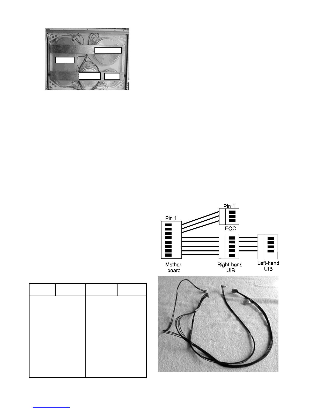
Harness
22
Reconnect the harness, if the F5 is still displayed, go to
the right hand user interface board as viewed from the
rear of the range. Notice that the harness to this board
has four wires and five pins. Disconnect the harness
plug from the board. With a voltmeter set to DC volts,
using a scale that will measure up to sixteen volts,
measure the voltage drop between pins one and two.
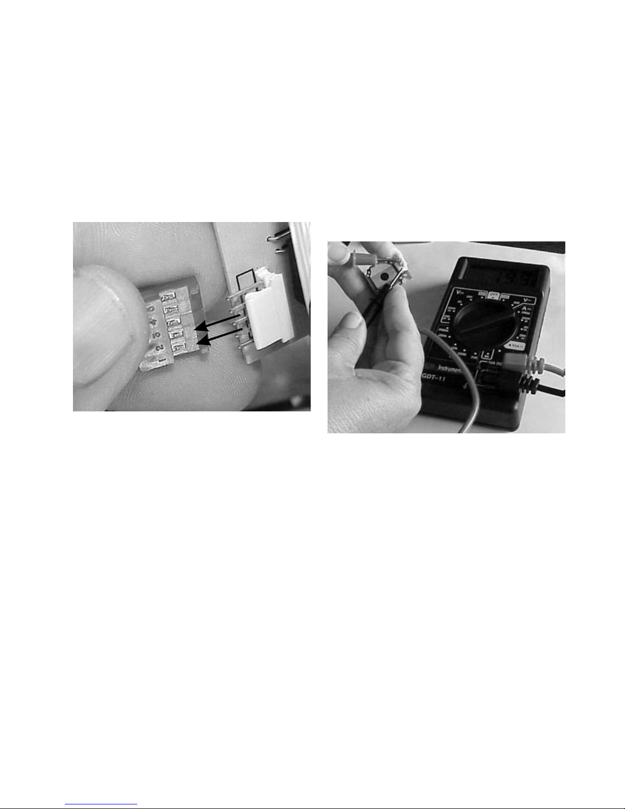
F7 code:
Indicates a failed potentiometer, a user interface board
or the harness between the mother board and the user
interface boards. To determine which has failed, check
the resistance of the potentiometers. The resistance
between the two outside pins should be within 10% of
the potentiometer value (black 10,000 Ohms, gray 20,000
Ohms). From the center pin to an outside pin the
resistance should vary between 500 and 9500 Ohms on
the black and 1000 and 19,000 Ohms on the gray, as
the shaft is turned.
Pins 1 & 2
If the reading is between 4 VDC and 12 VDC the mother
board is good. One at a time substitute a good user
interface board for the ones in the range. When the F5
code disappears that user interface board is defective. If
the reading is below four or above twelve volts DC replace
the mother board. If the F5 code does not disappear
recheck the harness and replace the user interface
boards one at a time.
F6 code:
Indicates a commnunication failure between the mother
board and the electronic oven control. This failure could
be caused by a defective wire harness between the EOC
and mother board, a faulty mother board, or faulty EOC.
Test the wire harness from the EOC to the mother board
with an ohm meter. If the harness checks good replace
the mother board. If the fault code is still present then
replace the EOC
Potentiometer test
NOTE: When testing from an outside pin to the center
pin the potentiometer must be turned on.
If the potentiometers test good, remove and Ohm out
the harness. If the harness checks good, reinstall the
harness and replace one of the user interface boards
with a new or known good board. Turn one of the top
elements on. If the element operates normal, replace
the user interface board. If the F7 reappears, turn the
top element off, reinstall the board that was replaced
and replace the other user interface board. Turn one of
the top elements on. If the element operates normal
replace that user interface board. If the F7 still appears,
recheck the harness.
Blank display:
If the display remains blank when an element is turned
on, listen to see if you hear a beep when the element is
turned on. If the range beeps, one of the user interface
23
boards or the harness between the mother board and
the user interface boards is defective. Remove and Ohm
out the harness. If the harness checks good, reinstall
the harness and replace one of the user interface board
with a new or known good board. Turn one of the top
elements on. If the element operates normal replace
that user interface board. If the display remain blank,
turn the top element off, reinstall the board that was
replaced and relpace the other user interface board. Turn
one of the top elements on. If the element operates
normal, replace that user interface board. If the display
remains blank, recheck the harness between the mother
board and the user interface boards. If you do not hear
the beep, replace the mother board.
Element not heating:
L1
Element
L1
H1
1A
2A
H2
L2
Indicator light
Troubleshooting:
There are four ways a warming zone system with a standard 120 VAC infinite switch can fail:
1. The element does not heat.
2. The switch does not cycle the element off and
on when set to a position other than high.
N
If an element or portion of an element does not heat but
the display shows the correct indication, either the mother
board, the element, or the element wiring is defective.
To determine which is defective:
1. Turn all surface element switches off.
2. Check the wiring diagram on the range to see
which terminal on the mother board is wired to
that element or portion of that element.
3. With a voltmeter measure the voltage drop
between that terminal and neutral on the
mother board. If the meter reads line to neutral
voltage (120 VAC) the mother board is
defective. If the meter reads zero the element
or wiring to the element is defective.
4. Turn the switch to high, raise the cooktop, and
measure the voltage drop across the element.
If the meter reads line to line voltage (240 VAC)
the element is defective. If the meter reads
zero the wiring is bad.
Warm and serve zone:
The warm and serve zone circuit on smooth top ranges
uses a line to neutral (120 VAC) standard infinite switch,
a line to neutral (120 VAC) element with a built-in limiter
to protect the glass, and an indicator light.
3. The element operates correctly, but the
indicator light does not glow.
4. Indicator light glows with all the infinite switches
in the off position.
NOTE: If the indicator light glows very dimly
with the switches in the off position, this is caused
by a capacitive feed over in the wiring and can be
corrected by connecting a 100,000 Ohm 1/4 watt
resistor in parallel with the light.
Element does not heat:
Checking the system with a Voltmeter, if the element
does not heat up:
1. Remove the back panel of the backguard to
expose the switch terminals.
2. With a Voltmeter set for AC on a scale higher
than 120 Volts measure the voltage drop
between terminals L1 and L2. If the meter
reads zero the wiring between the main
terminal block of the range and the switch is
open. If the meter reads line to neutral
voltage (around 120 VAC) go to step 3.
3. With the switch turned on to the high position
measure the voltage drop between terminals
H1 and H2. If the meter reads zero the switch
is defective. If the meter reads line to neutral
voltage the switch is good. Go to step 4.
4. Raise the top and locate the two terminals on
the element with the wires from H1 and H2.
Measure the voltage drop between the two
terminals. If the meter reads zero the wires
between the switch and the element are open.
If the meter reads line to neutral (120 VAC) the
element is defective.
24

Element does not cycle:
If the element does not cycle when the switch is set in a
position other than high the switch is defective.
Indicator light does not glow:
If indicator light does not glow when the switch is turned
on, remove the back panel of the backguard, turn the
switch on, and measure the voltage drop between terminals H1 and neutral. If the meter reads zero the switch
is defective. If the meter reads line to neutral voltage
(around 120 VAC) the light or the wiring to the light is
defective.
Indicator light glows full brilliance with the warm
and serve switch turned off:
If indicator light glows full brilliance with the warm and
serve switch off, the switch is defective.
25
SECTION C - ELECTRONIC OVEN
CONTROL SYSTEMS
This section covers five electronic oven control systems.
timer can be set for any amount of time from 1 minute
to 11 hours and 59 minutes. (Note: If you press the
Down Arrow first, the timer will advance to 11 hours
and 59 minutes.)
1. ES 100
2. ES 200
3. ES 300
4. ES 400
5. ES 450
The ES 100 Electronic Oven Control System:
The ES 100 electronic oven control system is used to
control ovens on non self-cleaning model ranges.
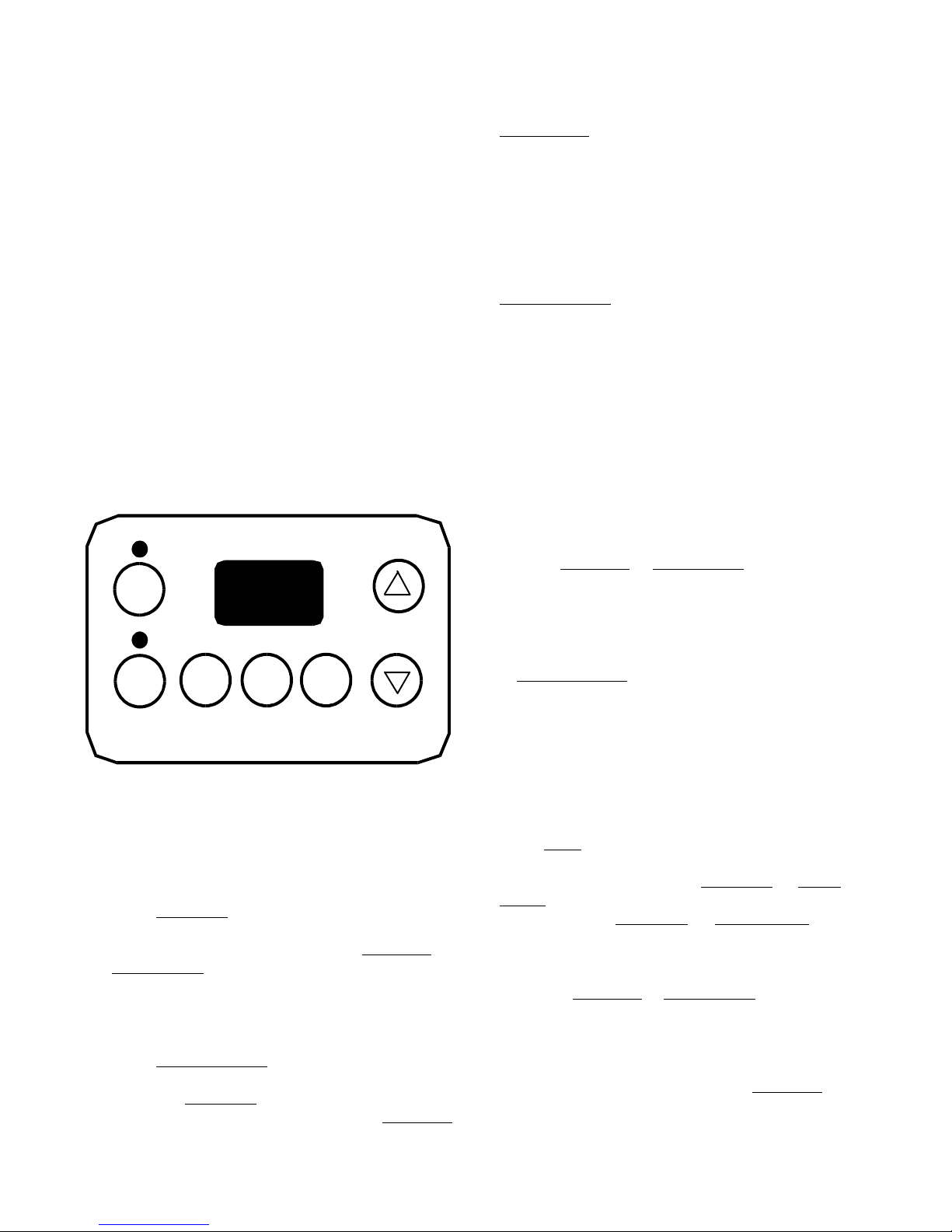
How to program the ES 100:
BAKE
3. The display shows the timer count down in minutes
until one minute remains. Then the display will count
down in seconds.
4. When the set time has run out, the timer will sound
a 3 second beep. 0:00 will appear in the display until
Timer ON/OFF is pressed.
NOTE: While the minute timer is counting down, the “:”
will flash. The minute timer does not start or stop
cooking. It serves as an extra timer in the kitchen that will
beep when the set time has run out. The minute timer can
be used alone or during any of the other oven functions.
When the minute timer is in use with any other function,
the minute timer will be shown in the display. To view
other functions, press the pad for that function.
To change the minute timer while it is in use:
While the timer is active and shows in the display, press
and hold the
Up Arrow or Down Arrow to increase or
decrease the time.
To cancel the minute timer before the set time has
run out:
BROIL
TIMER
ON/OFF
CLOCK
SET
CLEAR
OFF
To set the clock:
When the range is first plugged in, or when the power
supply to the range has been interrupted, the display will
flash "12:00".
1. Press Clock Set .
2. Within 5 seconds, press and hold the Up Arrow or
Down Arrow until the correct time of day appears
in the display.
To set the minute timer:
1. Press Timer ON/OFF .
2. Press the Up Arrow to increase the time in one
minute increments. Press and hold the Up Arrow
to increase the time in 10 minute increments. The
Press Timer ON/OFF .
To set or change the temperature for baking:
The oven can be programmed to bake at any temperature
from 170°F to 500°F.
To set the controls for baking:
1. Press Bake. "— — —°" appears in the display.
2. Within 5 seconds, press the Up Arrow or Down
Arrow. The display will show "350°F." By pressing
and holding the Up Arrow or Down Arrow, the
temperature can then be adjusted in small 5°F
increments.
3. When the Up Arrow or Down Arrow is released,
the oven will begin heating to the selected temperature.
When the displayed temperature reaches the desired
baking temperature, the control will beep 3 times.
4. To cancel the baking function, press Clear Off .
To change the oven temperature after baking has
started:
26

1. Press
Bake and make sure the bake temperature is
displayed.
2. Press the Up Arrow or Down Arrow to increase
or decrease the set temperature.
THE BAKE OR BROIL ELEMENT WITHOUT DISCONNECTING ELECTRICAL POWER FROM THE
RANGE. ELECTRICAL POWER IS CONNECTED
TO THE ELEMENTS WHENEVER ELECTRICAL
POWER IS CONNECTED TO THE RANGE.
To broil:
1. Arrange oven rack while oven is still cool. Position
the rack as suggested in the chart below.
Rack Position From Top Food
1 Rare steaks
2 Fish, medium
steaks,
hamburgers and
chops
3 Well-done foods
such as chicken
and lobster
2. Press
Broil.
3. Press and hold the Up Arrow or Down Arrow until
the desired broil setting level appears in the display.
Press the Up Arrow for HI broil or the Down Arrow
for LO broil. Most foods can be broiled at the HI broil
setting. Select the LO broil setting to avoid excess
browning or drying of foods that should be broiled to
the well-done stage.
4. Place the insert on the broiler pan, then place the
food on the insert. DO NOT use the broiler pan
without the insert or cover the insert with aluminum
foil. The exposed grease could ignite.
5. Place the pan on the oven rack. Open the oven
door to the broil stop position when broiling.
The ES 100 electronic oven control system is made up
of two parts that control the bake and broil elements.
1. Electronic oven control.
2. Oven temperature sensor.
Bake:
When the bake pad is touched, and a temperature is set
with the up or down arrows, the bake relay on the board
closes. This connects one side of the line to the bake
element. In the tip of the oven sensor is a positive
thermistor that increases in resistance as the oven
temperature increases. The microprocessor reads the
resistance of the oven sensor, and compares it with
programmed temperature set into the control. When the
resistance of the oven sensor indicates temperature in
the oven is about 10 degrees above the programmed
temperature, the microprocessor opens the relay, which
removes power from one side of the element. When
power is removed from the element the oven temperature
begins to lower. As the oven temperature lowers the
resistance of the oven sensor decreases. When the oven
drops to about 10 degrees below the programmed
temperature, the resistance of the sensor tells the
microprocessor to close the bake relay contacts, and
provide power to the bake element once again.
NOTE: Oven controls may have a temperature
swing of more or less than 20 degrees. The
important thing is the average temperature in the
oven. The average temperature in the center of the
oven should be within 10 degrees of the
programmed temperature.
6. Broil on one side until food is browned; turn and cook
on the second side. Note: Always pull the rack out
to the stop position before turning or removing food.
7. When broiling is finished, press Clear Off.
CAUTION: SHOULD AN OVEN FIRE OCCUR,
CLOSE THE OVEN DOOR AND TURN OFF THE
OVEN. IF THE FIRE CONTINUES, USE A FIRE
EXTINGUISHER. DO NOT PUT WATER OR FLOUR
ON THE FIRE. FLOUR MAY BE EXPLOSIVE.
How the ES 100 operates:
CAUTION: NEVER ATTEMPT TO REMOVE EITHER
Broil:
When the broil pad is touched, and High or Low is set
with the up or down arrows, the broil relay on the board
closes. This connects one side of the line to the broil
element. In the tip of the oven sensor is a positive
thermistor that increases in resistance as the oven
temperature increases. The microprocessor reads the
resistance of the oven sensor, and compares it with a
programmed temperature set into the control. Usually
you do not want the broil element to cycle so the oven
door is opened to the broil stop position. If the door is not
opened the broil element will cycle when the set
temperature is reached.
27
 Loading...