

Electrolux KELVINATOR KSV53HRA, KELVINATOR KSV62HRA, KELVINATOR KSV70HRA Diagnostic Manual
Copyright 2015 ELECTROLUX HOME PRODUCTS PTY L TD Technical Services
ELECTROLUX HOME PRODUCTS PTY LTD
ABN 51 004 762 341
KELVINATOR
SPLIT SYSTEM
AIR-CONDITIONER
MODELS:
KSV53HRA
KSV62HRA
KSV70HRA
Issue: 7
Technical Publication Nº KSSSI90 Date: 12/15
DIAGNOSTIC MANUAL

Indoor Unit & PCB test board Error Display.
DISPLAY LED STATUS PAGE
Not Operating
No operation by use of remote control
3 to 6
E0
EEPROM parameter error
7
E1
Indoor / outdoor units communication protection
8 to 17
E3
Indoor Unit Fan Stall
30 & 31
E5
Open or short circuit of outdoor condenser pipe & compressor temperature sensors
18 & 19
E52
Open or short circuit of outdoor ambient temperature sensor
18 & 19
E6
Open or short circuit of room or evaporator temperature sensor
20
L2 & PA
High-temperature protection of condenser
21 & 22
P0
Module protection
23 & 24
P1
Over voltage or too low voltage protection
25
P2
Temperature protection of compressor top - low refrigerant charge
26 & 27
P4
Inverter compressor drive error
28& 29
LO & P91
Evaporator high-frequency low-temperature limit
30 & 32
Page 2 KSSSI90

Not Operating:
# While the unit is in “stand by” mode, check if the green stand by light is flashing at 1 Hertz?
# Try operating the unit by the forced operations button: By pressing the button once, the unit should
activate in Auto mode. By pressing this button twice, within five seconds, the unit should activate in
Cooling mode.
If the unit can be operated by the forced operations button & the green stand by light was flashing on the
display PCB assembly, prior to pressing forced operation button, check the remote controller.
If the unit can be operated by the forced operations button & the green stand by light was off on the
display PCB, replace the display PCB assembly.
Stand by indicator on Display PCB assembly.
Button located on top right hand side of
indoor unit behind filter cover.
Page 3 KSSSI90
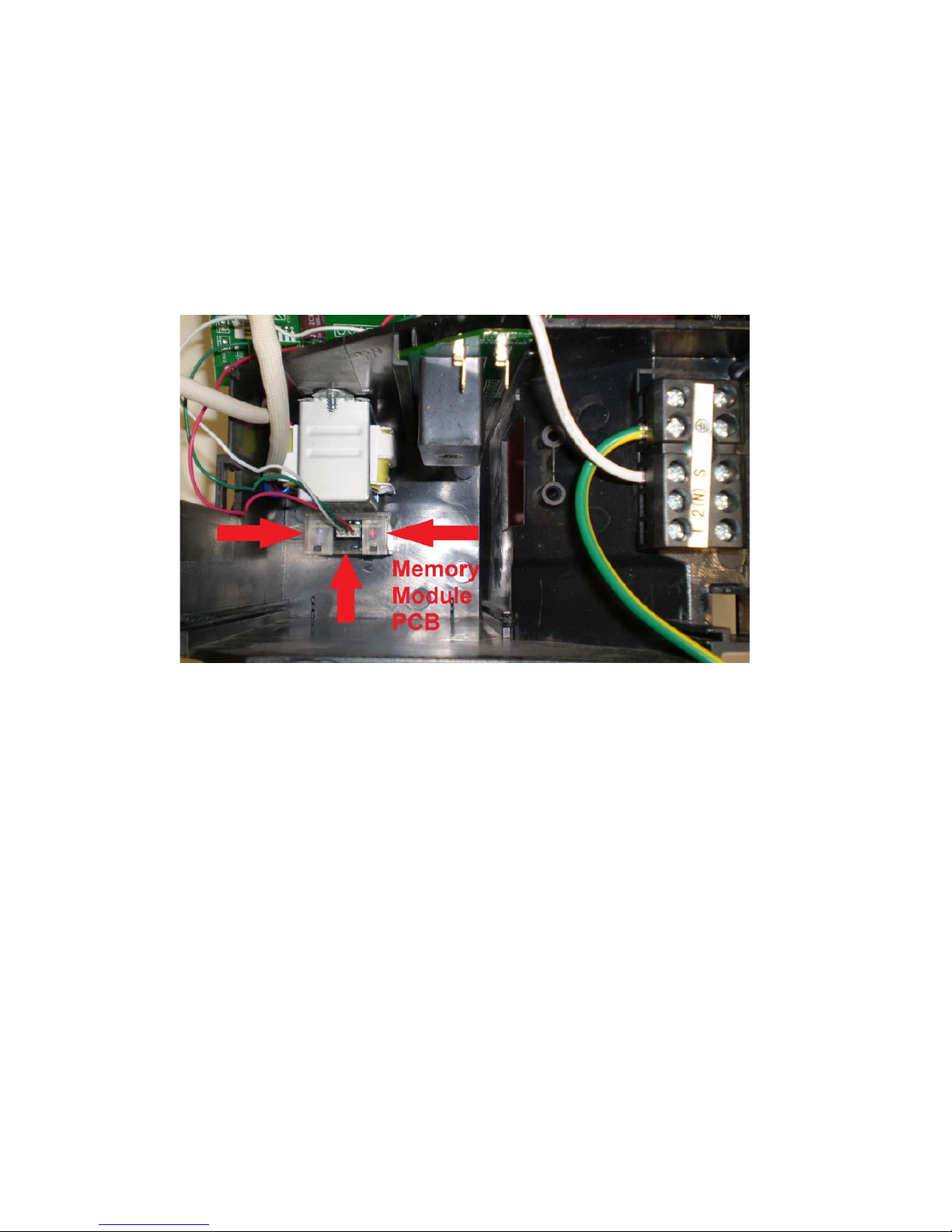
# If the frequency light is flashing & the unit can only be operated by the forced operations button.
The “Memory Module PCB” could be faulty. Refer attached photo’s
Note: There is no real way of isolating this Memory Module PCB & testing it, apart from replacing the
indoor control box assembly. As this component is not available as a induvial component.
Location of Memory Module PCB
(Indoor control box assembly)
Page 4 KSSSI90
# If the unit cannot be operated by the use of the remote control or the forced operation button, proceed
as follows:
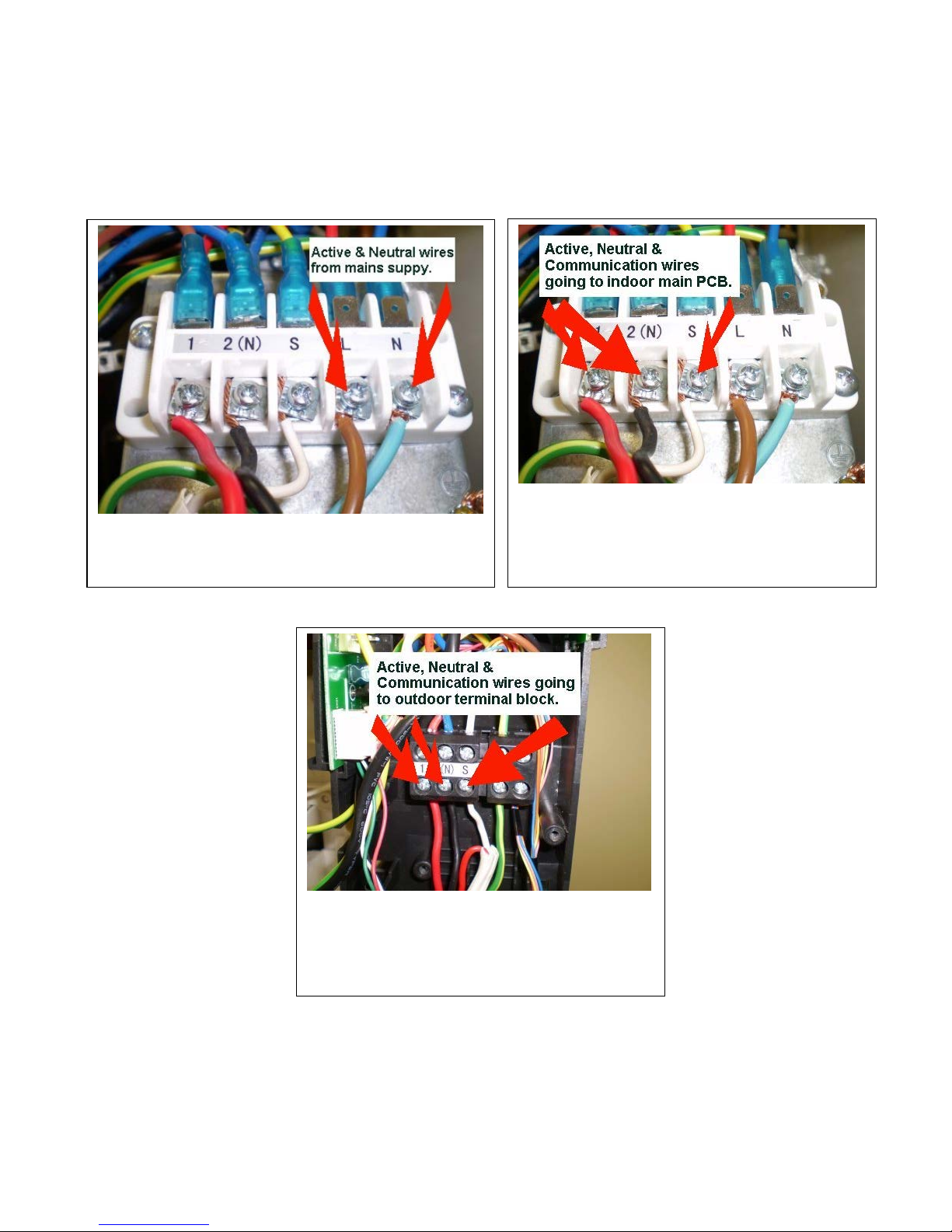
# Check the wiring configuration from the indoor unit to the outdoor unit. Is it wired up correctly in
accordance to the wiring diagram provided on the underside of the plastic outdoor terminal cover?
# Check the supply voltage to the outdoor terminal block.
# Check the supply voltage from the outdoor terminal block to the indoor terminal block.
Active & Neutral wires from mains supply.
Active, Neutral & Communication wires
connecting from outdoor terminal block to
indoor terminal block.
Active, Neutral & Communication wires from
outdoor terminal block.
Page 5 KSSSI90
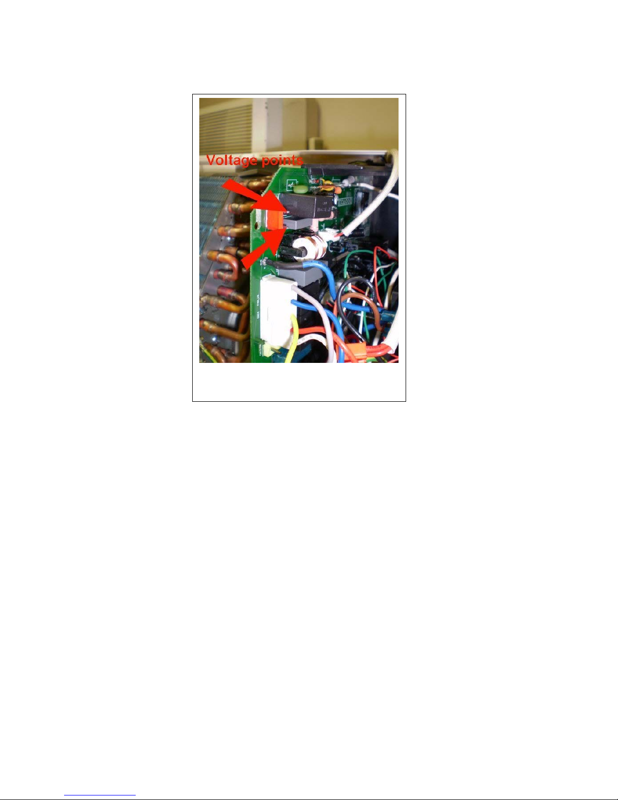
# Check the supply voltage from the indoor PCB to the transformer.
If there is 240 Volts AC from this connection point on the indoor PCB, replace the transformer.
If there is no supply voltage from this point, replace the indoor main PCB.
Transformer AC voltage connection points.
Page 6 KSSSI90
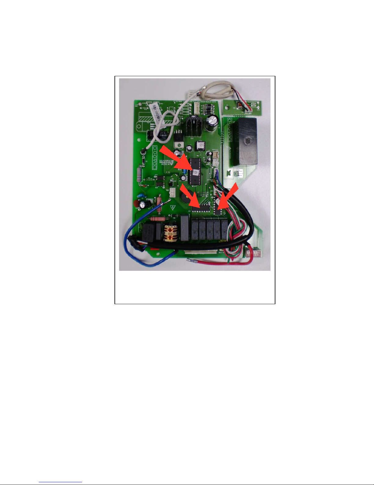
E0 error:
# The E0 error indicates there is a software issue/program chip fault on the main indoor PCB assembly.
# Replace the main indoor PCB assembly.
If any one of the program chips fail, as highlighted by
the red arrows, this could cause an E0 error.
Page 7 KSSSI90

E1 error:
(Indoor / outdoor units communication protection) error diagnosis and solution).
# Check for DC voltage at the following points:
• While in “standby mode”, disconnect the Signal Wire off the outdoor terminal block.
• With a multimeter, test the DC output from the signal wire connecting to the indoor unit &
earth.
• Then by using the same method, test the output signal on the terminal block from the outdoor
PCB & earth.
• If the meter reads a pulsing voltage in the 20's to the 40's (this can vary) the relevant PCB
should be okay.
• If the meter reads a 0 DC volts or a low stable voltage, this would indicate the PCB in
question is faulty.
Note: If both indoor & outdoor PCB’s appear okay, continue to the following page.
Page 8 KSSSI90
E1 error (Indoor Unit)
# Disconnect the main power supply to the outdoor unit by means of the isolation switch. After
approximately one minute, turn the power supply back on & attempt to operate the unit on heating or
cooling mode by the use of the remote control.
If E1 fault has not cleared:
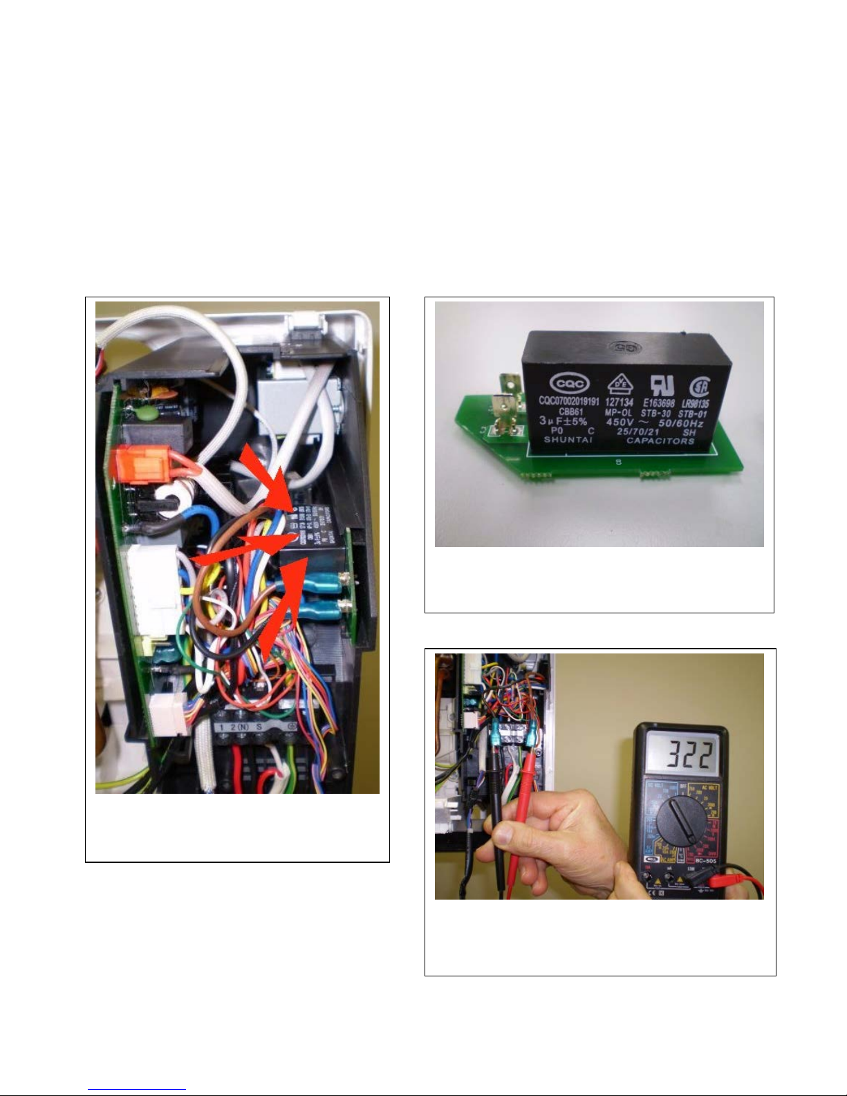
# Check the continuity of the (3uF) indoor fan capacitor mounted vertically inside the indoor control box
assembly.
# Measure the resistance of the Blue & Black wires that connect from the 3uF capacitor to the indoor fan
motor. The resistance reading should be approximately “322 Ohms”, at an ambient temperature of 22ºC.
3uF capacitor mounted inside the indoor
control box assembly.
3uF indoor fan capacitor.
Ohms reading of indoor fan motor.
Page 9 KSSSI90
E1 error (Outdoor Unit)
If E1 fault has not cleared:
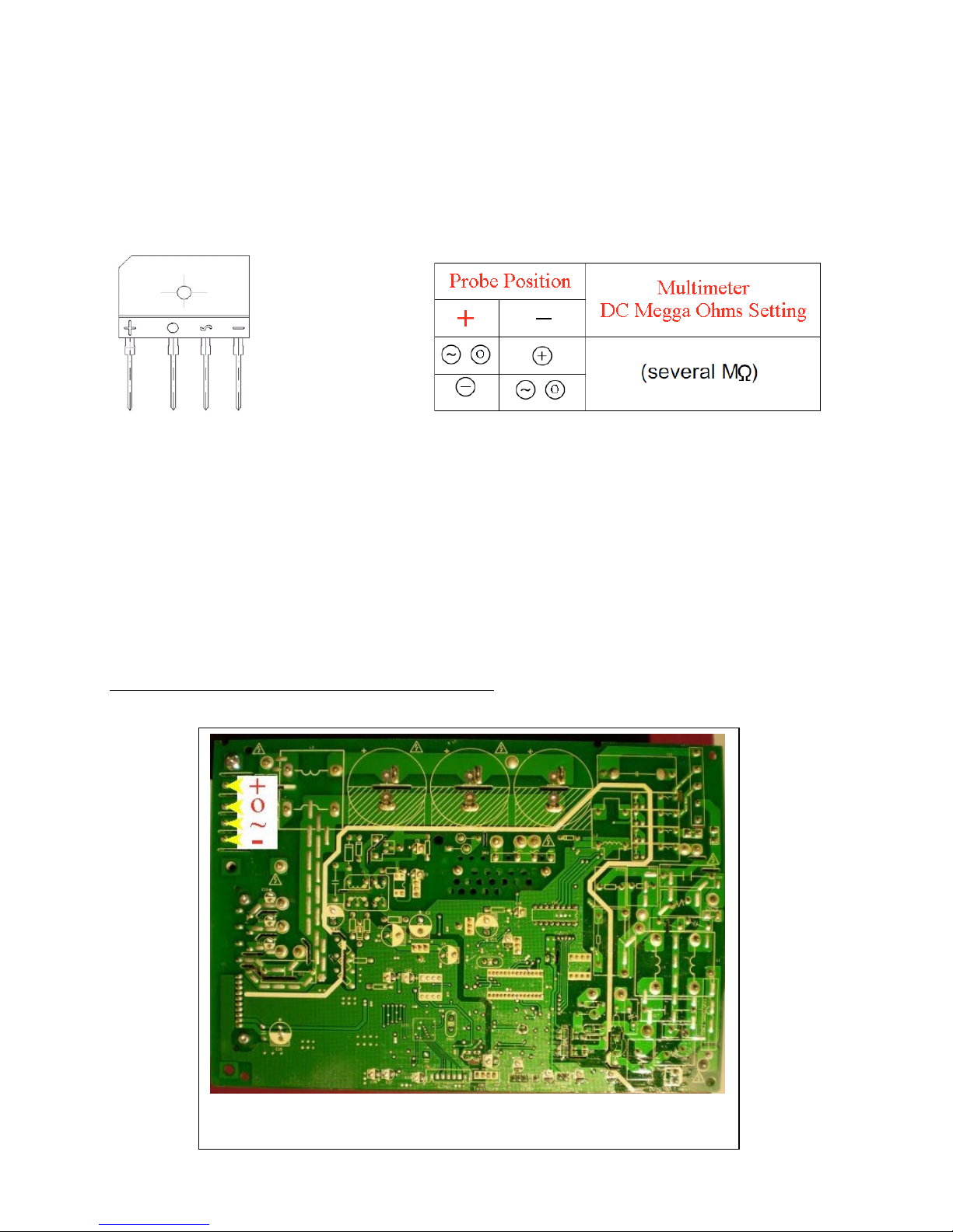
Check the continuity of the “Bridge Rectifier” as illustrated below.
Turn off the power & let the inverter electrolytic capacitors completely discharge.
Identify the diodes individual ‘Plus’ and ‘Minus’ connections so as to test each diode's forward and
reverse resistance values. The diagrams listed below illustrate the method of achieving this.
Relevant test points on the main outdoor PCB.
Set the multimeter to a DC Mega Ohms setting.
Place the Positive probe on the ~ pin of the rectifier & the Negative probe on the + pin of the rectifier.
Place the Positive probe on the O pin of the rectifier & the Negative probe on the + pin of the rectifier.
Place the Positive probe on the - pin of the rectifier & the Negative probe on the ~ pin of the rectifier.
Place the Positive probe on the - pin of the rectifier & the Negative probe on the O pin of the rectifier.
Note: Insure the multimeter probes are placed in their correct orientation as specified above.
Note: If any of the above tests indicate a “Short Circuit” replace the main PCB assembly.
All of the above tests should read several Mega Ohms.
Page 10 KSSSI90
 Loading...