

200100222
ISSUE 02/01
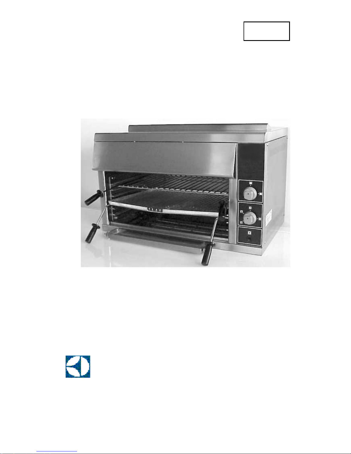
GAS SUPERGRILL/JET GRILL
USER’S INSTALLATION AND SERVICING MANUAL
Zanussi Professional
PNC: 283581; 283580
Model: GSG 580; JG/G580
Electrolux Foodservice
2
SPECIFICATIONS
Output 800 Model
Grilling(227gm steaks) 100/h
Toasting 400/h
Dimensions cm
Overall (wxdxh) 850x54x54
Heat Input
Btu/hkW (Natural Gas) 42,000/12.4
Net Weigh kg 50
GENERAL
The 600/800 GAS SUPERGRILL can be supplied for use
with either Natural Gas or LP (propane or butane). Details
will be found on the Data Plate fixed to the appliance. A
conversion kit is required to change from one gas supply to
the other. Supplied as kit at installation.
STANDARD EQUIPMENT
1. Toasting rack with crumb
2. Brander plate, frame and drip trough.
OPTIONAL EXTRAS
Bench stand
Wall bracket
Floor stand
Additional Branding plates
GAS DATA
MODEL TYPE OF GAS MODEL No
900 SUPERGRILL NATURAL GAS GSG 580NG
900 JETGRILL NATURAL GAS JG/G 580 NG
900 SUPERGRILL LPG GSG 580LP
900 JETGRILL LPG JG/G 580 LP
BURNER AND INJECTOR RATINGS
MAIN BURNER
MODEL TYPE OF GAS INJECTOR SIZE
900 Natural Gas 640 AMAL
900 Butane/Propane 200 AMAL
PILOT BURNER
MODEL TYPE OF GAS INJECTOR SIZE
900 Natural Gas N22
900 Butane/Propane N14
APPLIANCE PRESSURE
MODEL TYPE OF GAS PRESSURE
900 Butane 28mbar(11.2”WG)
900 Propane 37mbar(14.8”WG)
900 NG 20 mbar (8”wg)
BURNER RATING
MODEL TYPE OF GAS PRESSURE
900
Natural Gas
6.2kW/21,000Btu/h
900
Butane/Propane
6.2kW/21,000Btu/h
TOTAL RATING
MODEL TYPE OF GAS RATING
900
Natural Gas
12,4kW/42,000Btu/h
900
Butane/Propane
12,4kW/42,000Btu/h
SAFETY NOTES
1. It is the law that all gas appliances are installed by
competent person in accordance with the requirements of
the Gas Safety (Installation and Use) Regulations. Failure
to comply and install appliances incorrectly could lead to
prosecution. The Confederation for Resgistration of Gas
Installers (CORGI) requires its members to work to
recognised standards.
2. The installation of this appliance must be carried out in
accordance with these instructions, and meet with the
requirements of the Gas Safety Regulations, the Fire
Precautions Act, Local and National Building Regulations
and the recommendations contained in the revelant British
Standards Codes of Practice. The requirements of the
Health and Safety at Work Acts and Hygiene must be
observed.
3. This appliance is designed for commercial purposes only,
and must be operated by trained personnel.
4. This appliance is provided with an equipotential screw
fixing if required.
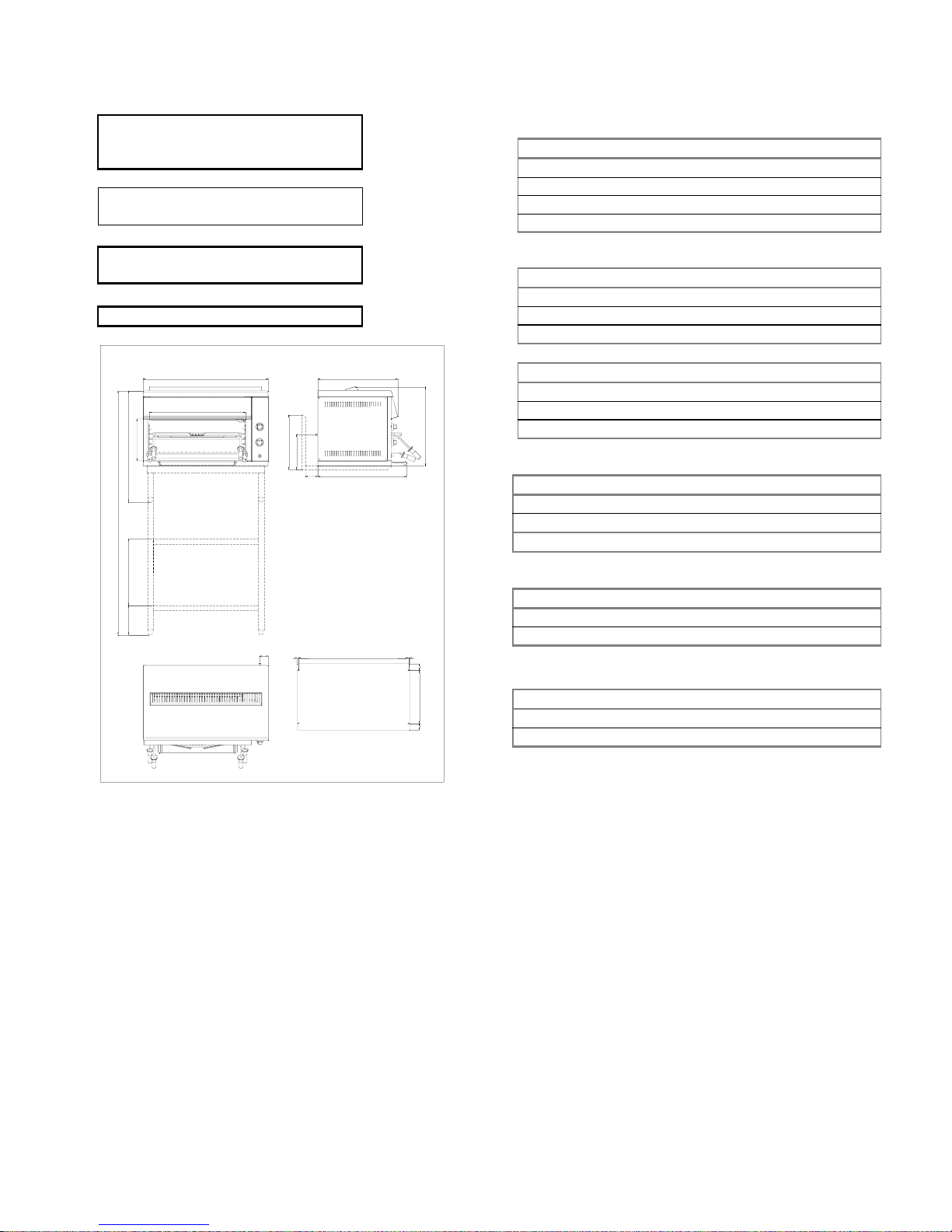
FIXING POINTS
2
8
5
850
5
3
8
540
4
0
0
5
0
5
0
33010 10
603
Dimension in mm.
Figure 1.
1
6
5
6
4
5
0
2
0
0
651
7
5
4
84
2
3
5
3
7
2
55

3
5. It is the responsability of the kitchen supervisor to warn
users of this appliance to wear suitable protective
clothing.
6. During normal operation, parts of this appliance will
become hot. Suitable precautions must, therefore, be taken
by the user to avoid accidental burns.
7. In the event of a fault developing, it is essential that the
appliance is isolated from the gas supply and a competent
person informed.
8. In the interest of safety and performance, regular
maintenance and servicing of the appliance is
important.To ensure that the appliance is in optimum
condition, periodical service and maintenance contracts
can be undertaken by the supplier. Equipment is inspected
and serviced by our engineers and, where necessary, faults
are rectified. Any replacement parts are quickly obtained
and fitted to bring the appliance into good working
condition.
GAS CONNECTION
Refer to the Date Badge (affixed to the lower Right Hand side
of the grill) to check that the appliance is compatible with the
available gas supply. The gas supply inlet is positioned at the
rear RH side of the appliance terminating in a Rp 3/8 (3/8”
BSP male taper) thread. For Natural Gas in UK, a gas
governor must be fitted in a supply as close to the appliance
as possible. For LP Gases, a low pressure regulator must be
fitted at the cylinder or supply tank.
The diameter of gas supply piping must not be smaller than
that of the appliance inlet (3/8” ID 9.5 mm). Long pipe runs
should be of a larger diameter in order to avoid excessive
pressure drops.
A gas Isolating Tap must be fitted in the gas supply pipe close
to the appliance for use in an emergency and to facilitate
servicing.
UPON COMPLETION OF THE INSTALLATION, THE
APPLIANCE AND SUPPLY PIPEWORK MUST BE
TESTED FOR GAS SOUNDNESS.
UPON SITING THIS APPLIANCE, AN
EQUIPOTENTIAL EARTH BOND CAN BE MADE
FROM THE GRILL AND ITS STAND TO ADJACENT
EQUIPMENT USING THE FIXED BOLTS LOCATED
AT THE REAR OF THE UNITS.
INSTALLATION
GENERAL
NOTE! It is necessary to employ a qualified engineer for the
installation and servicing of this appliance. It may be
necessary to change parts of appliance to suit the gas
supplied.
1. Before commencing installation remove all packaging.
Any protective film on the stainless steel panels may be
left on until installation is completed. HOWEVER all
protective film MUST BE REMOVED before the
appliance is commissioned.
2. Ensure that the area where the appliance is to stand is
level, and is capable of supporting the weight of the
appliance. If the support or surround is made of a
combustible material it is recommended that they shall be
clad by a suitable non-combustible heat insulating
material and that the local fire regulations are observed.
3. IMPORTANT: It is necessary to ensure an adequate
supply of fresh air to appliance for combustion and
ventilation. Kitchens require 20-40 changes of air per
hour.
4. THIS GRILL MUST NOT BE MOUNTED DIRECTLY
UPON A BENCH OR TABLE TOP, OR ON A SHELF.
The air necessary for safe combustion of the burners enters
from below the base of the appliance. Space, therefore,
must be allowed between the base of the appliance and the
supporting surface. A minimum of 50mm (2 inches) will
be sufficient. It is strongly recommended that use be made
of the optional Bench Stand, Wall Brackets, or Floor
Stand, in order to ensure a safe and comfortable working
height, and safe conditions.
THIS APPLIANCE MUST NOT BE MOUNTED ON A
SELF OR SUPPORT ABOVE A COOKING RANGE
WITHOUT SPECIAL SUPORT AND A GOOD
VENTILATION.
5. This appliance should preferably be installed below the
hood of an extraction system incorporating filters.
Should the installation be required without a ventilation
hood then a minimum distance of 1500mm (60 inches)
must be allowed between the top of the appliance and any
overlying shelf or ceiling. A distance of 150mm (6 inches
should be maintained between the back and sides or the
appliance and adjacent walls.
6. REMEMBER TO ALLOW SUFFICIENT ROOM AT
THE FRONT OF THE APPLIANCE TO ENABLE THE
SAFE WITHDRAWAL OF THE TOAST GRID AND
BRANDER PLATE.
COMMISSIONING
1. Remove all protective film and packaging from the
appliance.
2. Turn off the gas supply at the isolating tap.
3. Check that the appliance Main Control Tap is in the OFF
position.
4. Remove the gas Control Knobs.
5. Remove the Control’s Fascia and pull off the Piezo Cable.
6. Remove the pressure Test Point Sealing Screw.
7. Connect the pressure test gauge and replace Control
Knobs.
8. Turn ON the gas supply at Isolating tap.
9. Check for leaks at all joints inside the appliance AFTER
manually lighting Pilot and Main Burners. Following
lighting procedure.
10. Check than the gas pressure is correct when all Burners
are lit at FULL on. Adjust, if necessary, at the governor
(Natural Gas), or (if LP Gas) have the supplier of the gas
adjust the pressure at the tank or cylinder.
11. Check that the Main Burners and Pilot Burners extinquish
when the Main Control Tap is turned OFF.
12. Turn off appliance at the Control tap.
13. Turn OFF the gas supply at the Isolating Tap.

4
14. Remove the pressure test gauge and refit the Pressure Test
point Sealing Screw.
15. Turn ON the gas supply at the Isolating Tap and leak-test
the Pressure Test Point Sealing Screw.
16. Reconnect the Piezo Ignition Cable to the Igniter Unit on
the Control’s Fascia.
17. Turn the appliance Main Control Tap to the Ignition
position and operate the igniter button ensuring that the
Pilot Burner ignites safely.
18. Turn the Main Control Tap to OFF, remove the Control
Tap Knobs, and refit the Control’s Fascia Panel.
19. Check that the inner Top Panel can be easily removed and
refitted.
NOTE: When installation and commissioning is completed,
leave ALL the Instruction Manuals with a responsible person.
OPERATING
a) This appliance is designed for commercial purposes only
and must, therefore, be opereted by trained personnel.
b) It is the responsibility of kitchen supervisor to warn users
of this equipment to wear suitable protective clothing.
c) During normal operation, part of this appliance will
became hot, suitable precautions must, therefore, be taken
by users to avoid risk of accidental burns.
d) When using the Brander Plate, always fit the Drip/Basting
Trough, and empty it frequently, Don’t allow the Trough
to became too full or overflow, or too full to handle
safely.
e) Always pre-heat Brander Plate for approximately 20
minutes at FULL on before use.
NOTE: In event of a fault developing, it is essential to turn
OFF the gas at Isolating Tap, and inform a competent person.
LIGHTING PROCEDURE
IMPORTANT: SUPERGRILLS have two Main Burners with
a single Pilot Burner situated at the R.H. side within the
Grilling Compartment. Both Main Burners are controlled by a
Main Control Tap and a Front Burner Control Tap.
1. Check that the appliance Main Control Tap is in the OFF
position.
2. Turn ON the gas supply at the Isolating Tap.
3. Push the Main Control Knob in and turn to the IGNITION
position. An arrest will be felt to identify the position.
Keep the knob depressed.
4. Press the Ignition Button firmly (several times if
necessary) until the Pilot Burner flame ignites.
5. Hold the Main Control Knob pressed in for 20 seconds,
then release it. The Pilot Burner should stay alight. If the
Pilot Flame goes out, then repeat the procedure holding
the Main Control Knob pressed in for a longer period.
NOTE: The Pilot Burner can also be lit by applying a lit spell
or taper to the Pilot Burner whilst operating the Main Control
Tap as directed above.
TO OPERATE THE REAR BURNER
Once the pilot been established, the Rear Burner can be
turned on.
Turn the Main Control Knob anti-clockwise to the LOW
position. Rear Burner will automatically ignite from the Pilot
Burner.
The Main Control Tap will allow the Rear Burner to be
turned down to a low-flame setting for use when there is no
demand.
Turn the Main Control Knob further anti-clockwise from the
LOW to the HIGH position, for full on.
To revert to LOW, turn the Main Control Knob clockwise to
the LOW position.
TO OPERATE THE FRONT BURNER
The Front Burner Control Knob in position OFF the Front
Burner will be extinguished.
In position ON the Front Burner will be LOW/HIGH if the
Main Control Knob is in position LOW/HIGH.
TO TURN OFF
1. Turn the Main Control Knob clock-wise to the IGNITION
position, the Main Burner will extinguish BUT the Pilot
Burner will remain alight ready for Main Burner ignition
when required (standby).
2. Turn the Main Control Knob clock-wise to the OFF
position - both the Main Burner AND Pilot Burner will go
out.
COOKING
TOASTING
Follow lighting instructions.
Place the Toasting Grid - with the Crumb Tray in place on the
base of the Grill - in the third runner up from the grill base.
Place the bread on the Grid, as required. Alternative grid
positions are provided to suit individual preferences and the
thinckness of the bread.
GRILLING USING THE TOAST GRID
Grilling foods such as bacon, sausages, etc. can be carried out
using The Toast Grid, BUT always fit the Crumb Tray to
collect grease and juices.
The position of the Grid in the grilling compartment will
depend upon personal taste. Initially try the third runner up
from the base.
SALAMANDERING
For shallow dishes place them upon the Toasting Grid; for tall
(deep) dishes place upon the base of the grill. Use the Crumb
Tray - if there is any fear of spillage or boil over - placed
upon the base of the grill.
USING THE BRANDER PLATE
(Grilling Hearth)
The Brander Plate is thick cast aluminium plate having a
ribbed surface. It is mounted upon a special frame and has the
advantage to be able to be mounted flat or inclined in one of
several positions. The Crumb Plate should be stored upon the
base of the grill when using the Brander Plate.
 Loading...