

Page 1

ICE MAKER
SERVICE MANUAL
5995436457 5/2005
1
Page 2
SAFE SERVICING PRACTICES - ALL APPLIANCES
To avoid personal injury and/or property damage, it is important that Safe
Servicing Practices be observed. The following are some limited examples of
safe practices:
1. DO NOT attempt a product repair if you have any doubts as to your ability to
complete it in a safe and satisfactory manner.
2. Before servicing or moving an appliance:
• Remove the power cord from the electrical outlet, trip the circuit breaker to
the OFF position, or remove the fuse.
• Turn off the gas supply and allow any residual gas to dissipate for 10 to 20
minutes.
3. Never interfere with the proper operation of any safety device.
4. USE ONLY REPLACEMENT PARTS CATALOGED FOR THIS APPLIANCE.
SUBSTITUTIONS MAY DEFEAT COMPLIANCE WITH SAFETY
STANDARDS SET FOR HOME APPLIANCES.
5. GROUNDING: The standard color coding for safety ground wires is GREEN,
or GREEN with YELLOW STRIPES. Ground leads are not to be used as current
carrying conductors. It is EXTREMELY important that the service technician
reestablish all safety grounds prior to completion of service. Failure to do so
will create a hazard.
6. Prior to returning the product to service, ensure that:
• All electrical connections are correct and secure
• All electrical leads are properly dressed and secured away from sharp
edges, high-temperature components, and moving parts
• All non-insulated electrical terminals, connectors, heaters, etc. are
adequately spaced away from all metal parts and panels
• All safety grounds (both internal and external) are correctly and securely
connected
• All panels are properly and securely reassembled
ATTENTION!!!
This service manual is intended for use by persons having electrical and mechanical
training and a level of knowledge of these subjects generally considered acceptable in the
appliance repair trade. Electrolux Major Appliances cannot be responsible, nor assume
any liability, for injury or damage of any kind arising from the use of this manual.
© 2005 Electrolux Major Appliances
2
Page 3

Safe Servicing Practices 2
Quick Reference Sheet 4
Owner’s Guide and Parts Information 4
Contact Information 4
General information 5
Safety Precautions 5
Door Adjustment 5
Ice Production Rates 7
Customer Questions 7
Sequence of Operation 8
Automatic Shut-off 8
System and Time Chart 9
Leveling and Installation Requirements 10
Leveling the Unit 10
Installation Requirements 10
Gravity Drain Installation 11
Connecting a Drain Pump 12
Automatic Clean Cycle Instructions 12
Interior Storage Bin Cleaning 13
Sample Wiring Diagram 14
Compressor/Electrical Specifications 15
Compressor Pins 15
Specifications 15
Thermister 16
Check Light on Control Board 16
Low Side Pressure Changes 17
Ice Thickness Adjustment 18
Differences are as follows 18
Adjusting Ice Cube Thickness 19
Refrigeration System Diagnosis Guide 21
Troubleshooting 22
Unit does Not Operate
(with drain pump; light on control board is not illuminated) 22
Unit Does Not Operate
(withoutdrain pump; light on control board is not illuminated) 22
Unit Does Not Operate And light On Control Board Is Illuminated 22
No Ice Production 22
Low Ice Production 22
Will Not Eject Ice (water frozen) 23
Ice Is Slow To Release From Evaporator 23
Will Not Fill With Water 23
Continuous Ice Production 23
Low (Or No) Ice Production 24
Poor Ice Quality (soft or unclear cubes) 24
Unit Not Freezing (compressor and fan operating) 24
Unit Produces Shallow Or Incomplete Cubes Or The Ice
Fill Pattern On The Grid Is Incomplete 25
Not Freezing Compressor Not Running / Fan Operating 25
Not Freezing (compressor and fan not operating) 25
If the Unit Has A Drain Pump 25
Water Leak Under Unit 26
Water In Ice Bin 26
Water Will Not Stop Filling 26
Unit noisy 26
3
Page 4
QUICK REFERENCE SHEET
1. Owner’s guide and parts information may
be viewed or downloaded at:
2. Contact information:
Orders.
Canada Service, Warranty, General
Questions.
U.S.A. Service, Warranty, General
Questions.
Damage Claims.
Parts Orders.
Mailing Address.
www.electroluxusa.com
EHP Direct South: 1-800-845-4555
EHP Direct Northeast 1-800-611-4057
Fax 1-800-611-4058
EHP Direct North, Central & West 1-800-345-2566
Monday - Friday 8:00 AM - 5:00 EST 1-800-265-8352
Monday - Friday 8:00 AM - 5:00 EST
1-877-4Electrolux (435-3287) Electrolux ICON brands
1-800-456-4669 (option 3, then option 2)
1-800-320-0859
Electrolux Major Appliances
P.O. Box 212378
Martinez, GA. 30917
4
Page 5
GENERAL INFORMATION
Door Adjustment
Safety Precautions
Do not attempt to service or repair the unit until you
have read the entire procedure. Safety items throughout this manual are labeled with Danger, Warning or
Caution.
Risk of child entrapment. Before you throw away an
old refrigerator or freezer: Take off the doors, leave
shelves in place so that children may not easily climb
inside
• Never attempt to repair or perform
maintenance on the unit until the
electricity has been disconnected.
All model doors are aligned at the factory before shipment. Occasional readjustment may be necessary, especially if an Overlay Panel is installed. The following
procedure will correct for up to 1/4" alignment.
IMPORTANT
The door should never be flush with the top of the cabinet. Even when level, the top edge of the door will be
1/8" below the top of the cabinet
To adjust door:
• Altering, cutting of power cord,
removal of power cord, removal of
power plug, or direct wiring can
cause serious injury, fire and/or
loss of property and/or life and will
void the warranty.
CAUTION
• Do not lift unit by door handle.
• Never use an ice pick or other sharp
instrument to help speed up defrosting. These
instruments can puncture the inner lining or
damage the cooling unit.
• Failure to clean the condenser every three months
can cause the unit to malfunction. This could void
the warranty.
• Never install the unit behind closed doors. Be sure
front grille is free of obstruction. Obstructing free
air flow can cause the unit to malfunction, and may
void the warranty.
1. Compare the top edge of the door (opposite the
hinges) to the top edge of the cabinet and note the
type (up or down) of adjustment needed.
2. Remove the top hinge pivot pin with a 7/64" hex
wrench and lift door off bottom hinge
pin.
5
Page 6

Be careful not to lose door closer inserts.
Note: The hinge plate on some models do not
have the holes slotted for adjustment. New
hinge plates are available from Electrolux Parts.
3. With door upside-down, inspect the bottom hinge
plate mounting holes.
5. After adjustment is complete, remove the door
closers from the bottom hinge, clean thoroughly and
apply petroleum jelly to the mating surfaces of the
closers. Be sure that bosses on closers align with
holes in hinge and hinge plate. Mount door and
install top hinge pivot pin.
a. If your plate has slotted mounting holes, loosen
but do not remove the two hinge plate screws.
b. If your plate does not have slotted mounting
holes, remove the old plate and install the new
plate with the notch to the inside of the door.
4. If door edge opposite the hinges needs to move up,
move plate toward outside of door. If door edge
needs to move down, move plate toward inside of
door. Repeat until top edge of door is parallel with
top of cabinet and tighten screws securely.
6
Page 7
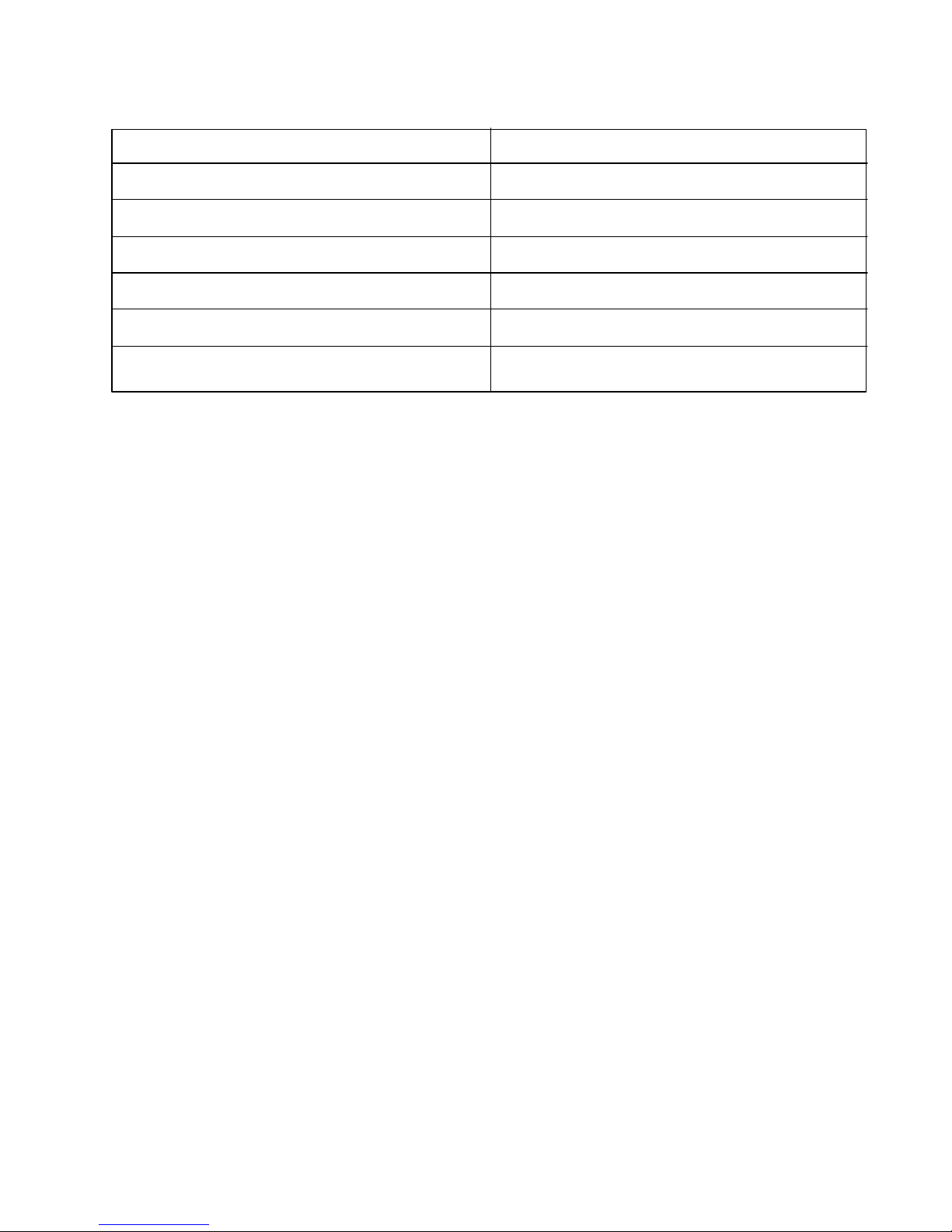
Ice Production Rates
Ambient Temp/Water Temp degrees F
50/50
60/50
70/50
80/50
90/70
100/70
NOTE: These characteristics will vary depending on
operating conditions, condenser cleanliness,
installation, and application.
Customer Questions
1. No ice or not enough ice!
Approximate Ice Production (lbs/day)
60
60
58
54
47
40
1. Factory specifications for ice production
60 lbs., bucket size 35 lbs.
2.Wet icecubes
3. The floor is very warm in front of the icemaker.
4. No ice, water pours into the trough and down into
the drain.
5. When the unit on is turned on, all I get is water fill.
6. My ice does not come out in a perfect cube shape
2. The storage bin that holds the ice is not
refrigerated. The cubes in the bin are slowly
melting down. The bin will maintain a temperature
of 32 to 34 degrees.
3. The unit is designed for a built-in application, so
the warm air will discharge out the bottom of the
unit below the door. There is a safety feature built
into the control board that will shut the unit down if
the warm air cannot be dissipated.
4. The standpipe needs to be inserted into the drain
hole of the water trough to maintain the proper
level of water inside the trough.
5. Check to be sure switch is in ice mode.
Once the unit is turned on, there will be a three
minute water fill. This will assure that a fresh batch
of water has filled the trough. If water flows more
than three minutes a service call will be required.
6. The manner in which the ice is made causes a
small hole or “dimple” to appear on the front or top
of the cube. Increasing or decreasing the time of
the freeze cycle will adjust the size of the dimple. A
service company will need to make this
adjustment.
7
Page 8

Customer Questions
7. The cubes do not fall into bin as individual cubes.
8. Not enough ice is stored in the bin.
Sequence of Operation
On initial start-up or restart, closing of bin thermostat,
the toggle switch is in the ICE position:
1. The water solenoid valve and hot gas solenoid
valve are opened (energized) for 180 seconds
(three minutes). This ensures the ice making cycle
starts with fresh water, and the refrigerant
pressures are equalized prior to compressor
start-up.
2. The compressor starts 175 seconds after the hot
gas solenoid valve and water solenoid valves are
opened.
3. The water pump and condenser fan motor are
energized. The hot gas solenoid valve and water
solenoid valves are de-energized (closed) five
seconds after the compressor starts. The unit is
now in the freeze cycle.
4. As the water pump circulates the water, an even
flow is directed across the evaporator and into
each cube cell, where it freezes. As the water
freezes, gravity causes any sediment to drop into
the water trough and not becoming imbedded in
the ice. This gives a clearer cube with low mineral
content.
7. Normal - You can use the scoop to break apart.
8. Check the level of the unit.
8. At the conclusion of the harvest cycle, the machine
returns to a new freeze cycle. The compressor
continues to run. The water pump and condenser
fan motor are energized. The hot gas solenoid
valve and water solenoid valves are de-energized
(closed).
Automatic Shut-off
The ice machine shut-off is controlled by the level of
ice in the ice storage bin. When the bin is full, ice
contacts the bin thermostat bulb holder, which senses
the cool temperatures, then opens which stops the
ice machine. The ice machine will remain off until the
ice cubes no longer contact the bin thermostat bulb
holder. This causes the bin thermostat to warm and
close, restarting the ice machine.
When the ice machine restarts, it returns to the startup sequence (steps 1, 2, and 3).
5. The control system automatically determines the
length of the freeze cycle by monitoring the
temperature of the refrigeration system “high side”
using a thermistor.
6. One minute prior to finishing the determined freeze
cycle, the control determines the length of the
harvest cycle by again monitoring the temperature
at the thermistor.
7. When the freeze cycle is completed, the control
de-energizes the water pump and the condenser
fan motor. The compressor remains running during
the harvest cycle. The control then energizes the
hot gas solenoid valve and water solenoid valve for
the duration of the harvest cycle. The hot
refrigerant gas warms the evaporator causing the
cubes to slide, as a sheet, off the evaporator and
into the storage bin. At the same time, the water
trough is being purged with fresh water.
8
Page 9
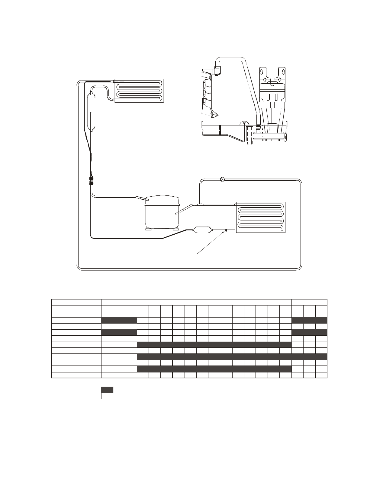
EVAPORATOR
EVAPORATOR
HOT GAS VALVE
CIRCULATION
NOTE: THE FREEZE/HARVEST CYCLE TIMES WILL VARY DUE TO OPERATING CONDITIONS.
System and Time Chart
ACCUMULATOR
PUMP
WATER
TROUGH
COMPRESSOR
CONDENSER
CYCLE DESCRIPTION
TIME (MINUTES)
WATER FILL VALVE
HOT GAS VALVE
WATER CIRCULATION PUMP
COMPRESSOR
CONDENSER FAN
ENERGIZED
NON-ENERGIZED
THERMISTOR SENSING POINT
INITIAL START UP
1 2 3
6 7 8 9 10 11 12 13 14 15 16 17 18 194
5
DRYER
FREEZE CYCLE
HARVEST CYCLE
9
Page 10

Leveling and Installation Requirements
It is extremely important that the unit is level.
If it is not level, the ice mold will not fill evenly. This can
cause a reduction in ice rate, uneven sized cubes or
water spilling into the storage area which will cause the
ice in the bin to melt prematurely.
Remember the floor surrounding a drain has a tendency
to slope towards the drain.
Leveling the Unit
2. If the ice maker is not level, adjust the feet on the
corners of the unit as necessary.
TURN FOOT TO ADJUST
3. Check after each adjustment and repeat the
previous steps as necessary until the unit is level.
Installation Requirements
• The unit may be built into a cabinet. There is no
minimum clearance requirement for the top, left or
right sides of the unit.
1. Use a level to check the ice maker from front to back
and from side to side.
• The location must allow enough clearance for water,
drain, and electrical connections in the rear of
the unit.
• The location must not obstruct air flow to the front of
the unit.
10
Page 11

Gravity Drain Installation
Caution: Plumbing installation must observe all state and local codes.
These guidelines must be followed when installing drain lines to prevent water from flowing back into the ice
maker storage bin and potentially flowing onto the floor causing water damage:
• Drain lines and fittings must have a 5/8" inside diameter.
• Drain lines must have a 1" drop per 48" of run (1/4" per foot) and must not create traps.
• The floor drain must be large enough to accommodate drainage from all drains.
• Insulate the bin drain line to prevent condensation.
Be sure to follow these guidelines to prevent water backing up into the storage bin.
Below are examples of gravity drain line installations. If a trap is in the drain line, the drain line must be vented to
assure proper draining. Without the vent, water will backup until enough pressure builds up to force the water
past the trap. Water may backup into the ice bin before the amount of pressure needed is achieved. Water in the
storage bin will cause the ice in the bin to melt prematurely.
The customer’s complaint will be slow ice production. The ice that has been made is melting prematurely
because water is backing up in the ice bin.
From Ice Maker To Floor Drain
1. Normal Drain.
Proper Drainage Pitched
from ice maker at least
1/4" per foot.
2. With Trap. Poor Drainage
Poor drainage. Water backs
up in drain line.
3. With Trap and Vent. Proper
Drainage Vent assures
proper drainage.
Examples of Gravity Drain Installations
Proper Drainage
Poor Drainage
Proper Drainage
11
Page 12

Connecting a Drain Pump
Caution: Plumbing installation must observe all
state and local codes. All water and drain
connections MUST BE made by a
licensed/qualified plumbing contractor.
Failure to follow recommendations and
instructions may result in damage and/
or harm.
If a gravity drain connection is not available, Electrolux
strongly recommends the use of the Electrolux drain
pump. If your ice maker is not equipped with a factory
installed pump, a drain pump is available through your
Dealer, or direct Electrolux. If a pump other than the
Electrolux drain pump is to be used, it must meet the
following specifications:
Caution: Use only Electrolux Ice Machine Cleaner.
It is a violation of Federal law to use this
solution in a manner inconsistent with
its labeling. Use of any other cleaner can
ruin the finish of the evaporator and will
void the warranty. Read and understand
all labels printed on the package before
use. Ice machine cleaner is used to
remove Lime scale and other mineral
deposits. Refer to the following steps for
mineral deposit removal.
1. Set the cycle selector switch (located in the center
of the grille) to OFF. Allow the ice to melt off of the
evaporator.
2. Remove all ice from the storage bin.
• It must be UL listed and have a UL listed, 120 VAC,
3-wire grounded power cord.
• Overall maximum outside dimensions of 8-3/4" wide
x 5-3/4" deep x 7-3/4" high.
• Minimum flow rate of 15 gallons per hour at 10 feet
of lift.
• It must have a sealed sump which does not allow
water leakage in the case of a power outage,
restricted drain or pump failure.
• It must have a check valve in the discharge line to
prevent waste water return to the pump.
• It must have an overflow protection control which
will shut off power to the ice maker in the event of
a pump failure.
• Operating temperature range of 50°F to 110°F (10°C
to 40°C).
If your ice maker is not equipped with an Electrolux drain
pump or an equivalent drain pump, severe damage and
costly repair could result in the event of a power outage, restricted drain or pump failure.
3. Remove inside front cover by gently pulling away
from side wall.
FRONT COVER
4. Remove the overflow tube by lifting it up while using
a slight back and forth motion to loosen it from the
drain hole.
Automatic Clean Cycle Instructions
To maintain operational efficiency, clean unit every six
months (depending on water conditions more or less
frequent cleaning may be necessary). If the ice maker
requires more frequent cleaning, consult a qualified
plumber to test the water quality and recommend appropriate treatment. Use only Electrolux Ice Machine
Cleaner.
OVERFLOW
The water in the reservoir will flow down the drain.
12
Page 13

5. Replace the overflow tube after all the water has been
drained from the reservoir.
6. Move the cycle selector switch to the CLN position.
7. When water begins to flow over the evaporator,
approximately three minutes, add one packet of
Electrolux Ice Machine Cleaner to the reservoir.
8. Reinstall inside front cover.
9. When the self cleaning process stops, approximately
45 minutes, it maybe desirable to clean the storage
bin. See INTERIOR STORAGE BIN CLEANING.
10.Move the cycle selector switch to the ICE position
to resume ice production.
Interior Storage Bin Cleaning
1. Disconnect power from the ice maker.
2. Remove any ice from the storage bin.
3. Wipe down the storage bin with a solution of
nonabrasive mild soap or detergent and warm
water. Rinse with clean water. Sanitize the bin with
a solution of one tablespoon of bleach and one
gallon of water. Rinse thoroughly with clean water.
4. Check that all drain connections are in place.
5. Reconnect power to the unit.
13
Page 14

Sample Wiring Diagram
Note: Always refer to diagram on ice maker.
14
Page 15

Electrical Specifications
R S
C
Compressor Pins:
To measure start winding resistance, measure across the C-S pins.
To measure run winding resistance, measure across the C-R pins. These pins should never measure any
resistance to ground. This would indicate a shorted compressor.
Specifications:
Compressor Start Winding: 12.0 OHMS.
Compressor Run Winding: 2.9 OHMS.
STARTING
RELAY
3/4" OVERLOAD
PROTECTION
Water Valve Coil Resistance: 280 OHMS.
Bypass Coil Resistance: 380 OHMS.
Pump Motor Winding Resistance: 71.5 OHMS.
15
Page 16

Thermistor
Check Light on Control Board
The thermistor senses the refrigeration system “high
side” temperature. This is used in conjunction with
the control board to determine the length of the freeze
and harvest cycles.
Thermistors generally fail due to moisture or physical
damage. Electrolux “high side” thermistors are
encased in a specially-designed, moisture-sealed aluminum block. The thermistor is also mounted to
the “high side” or “dry” portion of the refrigeration system. This eliminates physical damage and
moisture concerns.
The LED light on the control board serves three functions.
1. Steady light - The control board has power to it and
operation is normal.
2. Slow flash - The control board has detected a
sensor problem. This will happen if the thermistor’s
plug is disconnected from the control board. This
will also happen if the thermistor fails open.
3. Rapid flashing - This indicates the control board is
receiving a high heat signal from the thermistor. This
can be caused by a dirty condenser, inadequate air
flow (unit installed behind closed doors), failed
condenser fan motor, etc.
In both the slow flash and rapid flashing situations, the
unit will stop operation.
LED Light
16
Page 17

Low Side Pressure Changes
The chart below shows the low side pressure changes
through the cycles of a Electrolux ice maker. It shows
that during a harvest cycle, the low side pressures climb
to nearly 60 psig. When the freeze cycle starts, the pressure quickly drops to approx. 17 psig and throughout
the freeze cycle it continues to slowly drop to approximately 7 psig just before the harvest cycle.
This unit was operating in a 75° Fahrenheit ambient temperature and the incoming water temperature was 50° farenheit.
If a unit is operating in conditions other than
these, the low side pressures will be different.
17
Page 18

Ice Thickness Adjustment
The Clear Ice Maker uses advanced technology to make
ice that is crystal clear. This technology cascades a flow
of water over a chilled ice mold that is mounted vertically so no water sits in it. Because of this ice making
technology, clear ice cubes differ significantly from regular ice cubes.
Differences are as follows:
• Dimples. Electrolux clear ice cubes have “dimples”
on one side from the cascading water process.
• Cube Variations. Cubes made from different batches,
or even cubes within the same batch may have
varying dimples, thicknesses and/or sizes due to the
cascading water process.
• Cube “slabbing”. The Electrolux clear ice maker
makes a “slab” of ice that falls from the vertical mold
relying on gravity to break the ice bridges.
Depending on the control setting, and the fullness of
the ice bucket, it maybe necessary to tap the ice
slab with the scoop to break it apart.
The ice cube thickness control is factory set for best
overall performance. The factory setting is designed to
maintain an ice bridge of approximately 1/16" to 1/8"
under normal conditions resulting in a dimple of
approximately 1/4" to 1/2" in depth.
1/4" TO 1/2"
DIMPLE
GOOD
A fuller cube with less of a dimple results in a thicker ice
bridge. As the ice bridge becomes thicker, the tendency
for the cubes to stay together as a slab increases.
BRIDGE
DIMPLE
TOO THIN
TOO DEEP
LITTLE OR
NO DIMPLE
1/16" TO 1/8"
ICE BRIDGE
BRIDGE
TOO THICK
ICE BRIDGE
DIMPLE
BAD
A bridge thicker than 1/8" may cause cubes to overfill
the ice bucket.
18
Page 19
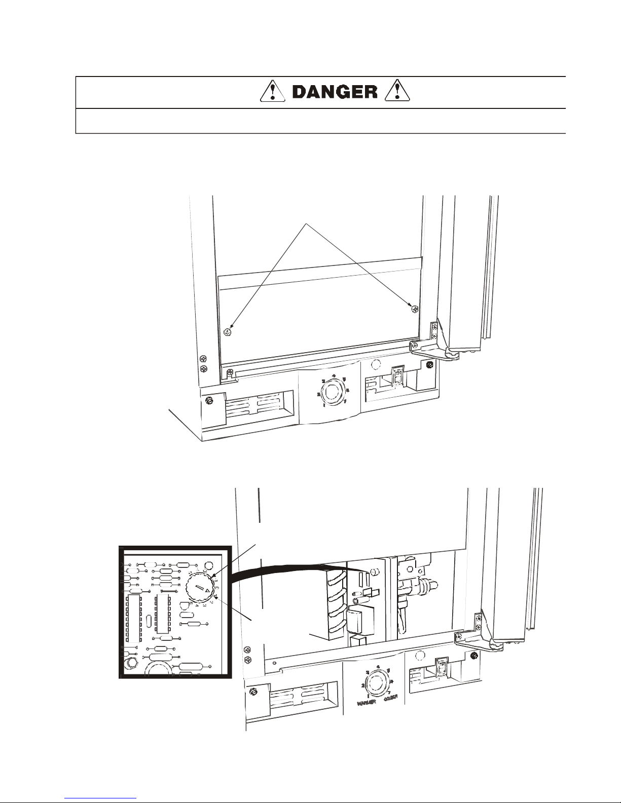
Disconnect power to the ice maker before making any ice thickness adjustments.
Adjusting Ice Cube Thickness:
1. Disconnect power to the unit.
2. Remove the screws securing the front access panel.
ACCESS PANEL SCREWS
WARMER
R
E
D
L
O
C
3. Locate the ice cube thickness adjustment dial on the control board. Turn the dial
clockwise (+ number) to thicken or counterclockwise (- number) to thin the ice bridge.
ICE CUBE THICKNESS
ADJUSTMENT
DIAL
DIAL IS FACTORY
SET TO +1
19
Page 20

IMPORTANT: The door should never be flush with the top of the cabinet. Even when level, the top
edge of the door will be 1/8" below the top of the cabinet.
SAMPLE AREA
4. Reinstall front access cover.
5. Reconnect power to ice maker.
6. Empty ice bucket.
20
Page 21

21
Page 22

Troubleshooting
DANGER
DO NOT service the unit until the main
electrical power has been disconnected.
Problem
1. Unit does not operate (with
drain pump; light on control
board is not illuminated).
2. Unit does not operate (without
drain pump; light on control board
is not illuminated).
3. Unit does not operate and light
on control board is illuminated.
Cause
a. No electrical power to the unit.
b. Rocker switch set incorrectly.
c. Drain tube is kinked or
obstructed.
d. Bad pump. Diagnose by
bypassing the pump. Pull both
pink wires from control board
and jump the two terminals
together. If unit starts up, then t
he pump is bad.
a. No power to unit.
a. Bad bin thermostat.
Correction
a. Make sure unit is plugged in and
outlet has power.
b. Check switch wiring. Set to “ICE.”
c. Clear the tubing. If water cannot
drain from pump, unit will shut
down due to safety design of
pump.
d. Change pump. Jumping the two
terminals together on the control
board with a jumper wire will
eliminate pump from the circuit.
a. Jumper plug off power cord.
Remedy
a. Replace bin thermostat. The unit
is falsely sensing a full bin.
Cause
4. No ice production.
Cause
5. Low ice production.
Cause
Cause
NOTE: Light on control board will indicate if condenser is too dirty. A rapid flash of light indicates high
heat conditions which could be caused by either an inadequate air flow or a dirty condenser.
b. Bin thermostat set incorrectly.
a. No water supplied to unit.
b. Stand pipe not inserted in water
trough.
c. Re-circulating pump is defective.
a. High ambient temperatures
around unit.
b. Deposit build-up on evaporator
grid.
c. Ice thickness dial set incorrectly.
d. Dirty condenser coil.
b. Set bin thermostat at the 10:00
position.
Remedy
a. Check that water is connected
and turned on.
b. Insert stand pipe securely into
water trough.
c. Replace re-circulating pump.
Remedy
a. Lower ice rate is normal with high
ambient temperatures.
b. Run the unit through a clean
cycle. Use only Electrolux Ice
Machine Cleaner.
c. Adjust ice thickness dial
accordingly.
d. Clean condenser coil.
Remedy
Cause
22
Page 23

Problem
6. Will not eject ice (water frozen).
Cause
Cause Correction
a. Bin thermostat set incorrectly.
a. Set bin thermostat at 10:00
position.
7. Ice is slow to release from
evaporator.
Cause
8. Will not fill with water.
Cause
b. Wiring plug off of bypass valve
coil.
c. Defective bypass valve.
d. Deposit build-up on evaporator
grid.
a. Deposit build-up on evaporator
grid.
b. Unit not level.
a. No stand pipe in water trough.
b. Water valve is defective.
c. Water solenoid unplugged or wire
to solenoid has internal break.
b. Re-install plug.
c. Replace bypass valve.
d. Run unit through the clean cycle.
Use only Electrolux Ice Machine
Cleaner. If scale or mineral
deposits accumulate on grid,
cubes will not fall freely.
Remedy
a. Run unit through the clean cycle.
Use only Electrolux Ice Machine
Cleaner.
b. Level unit for even water flow.
Uneven water flow will reduce ice
rate and cause water to spill in
ice bin.
Remedy
a. Install stand pipe.
b. Replace valve.
c. Repair wiring defect.
Remedy
9. Continuous ice production.
Cause
a. Bin thermostat set too cold.
b. Bin thermostat sensing bulb out
of alignment.
c. Bin thermostat stuck in closed
position.
d. Ice slab too thick.
a. Set bin thermostat to the 10:00
position.
b. Insert bulb inside aluminum
sensor tube.
c. Replace bin thermostat.
d. Set ice thickness adjustment dial
to a lower setting. If cubes
release from grid and are too
thick, cubes might not make
contact with sensor tube
(inside of bin); therefore bin
thermostat would never be
satisfied.
Remedy
23
Page 24

Problem
10. Low (or no) ice production.
Cause Correction
a. Dirty condensing coil (Control
board light shows rapid flash).
a. Clean condensing coil.
11. Poor ice quality (soft or unclear
cubes)
Cause
12.Unit not freezing (compressor
and fan operating)
Cause
b. Stalled condenser fan blade
(Control board light shows a rapid
flash).
c. No water in water trough.
d. Bypass valve stuck in open
position.
e. Ice forms on a portion of
evaporator grid.
a. Poor incoming water quality.
b. Deposit build-up on evaporator
grid.
c. Water splashing on cubes.
a. Little or no cooling.
b. Free up the blade or replace fan
motor.
c. Install stand pipe securely in
trough.
d. Replace bypass valve.
e. Check unit for system under
charge or leak.
NOTE: See chart of suction
pressures in manual.
a. Consult a plumber.
b. Run the unit through a clean
cycle. Use only Electrolux Ice
Machine Cleaner.
c. Adjust water flow above
evaporator.
Remedy
a. Check sealed system for leak or
restriction.
NOTE: See chart of suction
pressures in manual.
Cause
b. Bypass valve stuck in open
position.
Cause
24
b. Replace bypass valve.
Remedy
Page 25

Problem
13.Unit produces shallow or
incomplete cubes or the ice fill
pattern on the grid is incomplete.
Cause
Cause Correction
a. Low water level.
b. Low water pressure.
a. Check that standpipe is fully
seated inside water trough.
b. Check water pressure into water
valve (pressure should be 20 to
120 psi).
14.Not freezing compressor not
running / fan operating.
Cause
15.Not freezing (compressor and
fan not operating)
c. Unit is not level.
d. Operating unit without back or
front panel.
e. Bad thermister.
f. Bad control board.
a. Bad overload (open).
b. Bad compressor.
a. No electrical power to unit.
c. Level unit to assure even water
flow. Uneven water flow will
reduce ice rate and cause
incomplete cubes. See Leveling
Instructions in manual.
d. Install back or front panel. The
unit will harvest ice according to
temperatures of tubing at
condensing coil. Increased air
flow will give the thermister false
information. This info could cause
the ice to eject prematurely.
e. Replace thermister.
f. Replace control board.
Remedy
a. Replace overload.
b. Replace compressor.
Remedy
a. Make sure unit is plugged in and
outlet has power.
16.If the unit has a drain pump.
Cause
b. Rocker switch defective or wired
incorrectly.
a. Drain tube kinked or obstructed.
b. Bad pump. Diagnose by
bypassing the pump. Pull both
pink wires from control board and
jump the two terminals together.
If unit starts up, then the pump is
bad.
c. Open wire in wiring harness.
Cause
b. Make sure switch is wired
correctly and set in “ICE” position.
a. Clear the tubing. If water cannot
drain from pump, unit will shut
down due to safety design of
pump.
b. Change pump. Jumping the two
terminals on control board
together with a jumper wire will
eliminate pump from the circuit.
c. Trace defective wire and repair
or replace parts accordingly.
25
Page 26

Problem
17.Water leak under unit.
Cause
Cause Correction
a. Incoming water supply line
leaking.
a. Make sure brass connection is
screwed tight to valve and
threaded correctly.
18.Water in ice bin.
Cause
19.Water will not stop filling.
Cause
b. Fill tube leaking.
a. Bin drain kinked or restricted.
b. External drain is restricted.
c. Bad pump.
a. Water solenoid stuck in open
position.
b. Open relay on control board.
NOTE: A defective relay on
control board would
cause both the water
valve and reversing
valve to stay open,
therefore, this failure
would not allow the unit
to freeze.
b. Tighten fill tube connection to
water line.
c. Unit not repairable. Contact
Electrolux tech line for
assistance.
Remedy
a. Clear drain of obstruction or kink.
b. Clear restriction.
c. Replace pump.
Remedy
a. Replace water valve.
b. Replace control board.
Remedy
20.Unit noisy.
Cause
a. Fan motor not secured to
bracket.
b. Fan blade bent.
c. Vibration from refrigerant lines.
d. Obstruction in fan blade.
a. Tighten motor.
b. Realign or replace blade.
c. Secure tubing.
d. Remove obstruction.
26
Page 27
NOTES
27
Page 28

28
 Loading...