

Page 1

27
Foreword
The installation, use and maintenance Manual (hereinafter Manual) provides the user with information
necessary for correct and safe use of the machine (hereinafter “machine”, “refrigerator” or “appliance”).
The following must not be considered a long and exacting list of warnings, but rather a set of instructions
suitable for improving machine performance in every respect and, above all, preventing injury to persons
and animals and damage to property due to improper operating procedures.
All persons involved in machine transport, installation, commissioning, use and maintenance, repair and disassembly
must consult and carefully read this manual before carrying out the various operations, in order to avoid wrong and
improper actions that could compromise the machine’s integrity or endanger persons. Make sure to periodically inform
the appliance user regarding the safety regulations. It is also important to instruct and update personnel authorised to
operate on the machine, regarding its use and maintenance.
The manual must be available to operators and carefully kept in the place where the machine is used, so that it is
always at hand for consultation in case of doubts or whenever required.
If, after reading this manual, there are still doubts regarding machine use, do not hesitate to contact the Manufacturer or
the authorised after-sales service centre, to receive prompt and precise assistance for better operation and maximum
efciency of the machine.
During all stages of machine use, always respect the current regulations on safety, work hygiene and environmental
protection. It is the user’s responsibility to make sure the machine is started and operated only in optimum conditions
of safety for persons, animals and property.
The manufacturer declines any liability for operations carried out on the appliance without respecting the
instructions given in this manual.
No part of this manual may be reproduced.
EN
Page 2
28
A.1 GENERAL INFORMATION
A.1.1 INTRODUCTION
Given below is some information regarding the machine’s intended
use, its testing, and a description of the symbols used (that identify
the type of warning), the denitions of terms used in the manual
and useful information for the appliance user.
A.1.2 INTENDED USE AND RESTRICTIONS
Our appliances are designed and optimised in order to obtain
high performance and efciency. This appliance is designed
for the refrigeration and preservation of foods. Any other use is
deemed improper.
The appliance must not be used by people (including children)
with limited physical, sensory or mental abilities or without
experience and knowledge of it, unless instructed in its use by
those responsible for their safety.
ATTENTION: The machine is not suitable for installation outdoors
and/or in places exposed to atmospheric agents (rain, direct
sunlight, etc.).
ATTENTION!
Do not store explosive substances, such as
pressurisedcontainerswithammablepropellant
( ), in this appliance.
The manufacturer declines any liability for improper use of
the product.
A.1.3 TESTING AND INSPECTION
Our appliances are designed and optimised, with laboratory
testing, in order to obtain high performance and efciency. The
product is shipped ready for use.
Passing of the tests (visual inspection - electrical test - functional
test) is guaranteed and certied by the specic enclosures.
A.1.4 DEFINITIONS
Listed below are the denitions of the main terms used in the
manual. Read them carefully before using the manual.
Operator
machine installation, adjustment, use, maintenance, cleaning,
repair and transport personnel.
Manufacturer
Electrolux Professional SPA or any other service centre
authorised by Electrolux Professional SPA.
Operator for normal machine use
an operator who has been informed and trained regarding the
tasks and hazards involved in normal machine use.
Technical assistance or specialised technician
an operator instructed/trained by the Manufacturer and who,
based on his professional and specic training, experience and
knowledge of the accident-prevention regulations, is able to
appraise the operations to be carried out on the machine and
recognise and prevent any risks. His professionalism covers the
mechanical, electrotechnical and electronics elds.
Danger
source of possible injury or harm to health.
Hazardous situation
any situation where an operator is exposed to one or more
hazards.
Risk
a combination of probabilities and risks of injury or harm to health
in a hazardous situation.
Protection devices
safety measures consisting of the use of specic technical means
(guards and safety devices) for protecting operators against
dangers.
Guard
an element of a machine used in a specic way to provide
protection by means of a physical barrier.
Safety device
a device (other than a guard) that eliminates or reduces the risk;
it can be used alone or in combination with a guard.
Customer
the person who purchased the machine and/or who manages
and uses it (e.g. company, entrepreneur, rm).
Electrocution
an accidental discharge of electric current on a human body.
A.1.5 TYPOGRAPHICAL CONVENTIONS
For best use of the manual, and therefore the machine, it is
advisable to have good knowledge of the terms and typographical
conventions used in the documentation.
The following symbols are used in the manual to indicate and
identify the various types of hazards:
ATTENTION!
DANGER FOR THE HEALTH AND SAFETY OF
OPERATORS.
ATTENTION!
DANGER OF ELECTROCUTION DANGEROUS VOLTAGE.
ATTENTION!
RISK OF DAMAGE TO THE MACHINE.
Words further explaining the type of hazard are placed next to
the symbols in the text. The warnings are intended to guarantee
the safety of personnel and prevent damage to the machine or
the product being worked.
The drawings and diagrams given in the manual are not in scale.
They supplement the written information with an outline, but
are not intended to be a detailed representation of the machine
supplied.
The numerical values given on the machine installation diagrams
refer to measurements expressed in mm.
A.1.6 MACHINE AND MANUFACTURER’S IDENTIFICATION
DATA
A reproduction of the marking or dataplate on the machine is
given below:
Potenza Sbrinamento / Defrost Power xxxxx kW
x kW
Resistenza Evaporazione / Evaporation Heater El.
x W
Illuminazione / Lighting
Classe / Class x
xxx KgRefrigerante / Refrigerant xxxxx
Cap. xxx
IP21
Electrolux Professional SPA - Viale Treviso, 15 - 33170 Pordenone (Italy)
2015
Volt xxx xx xxHz
Ser.Nr. xxxxxxxx
Comm.Mod.
FOCLBT
F.Mod. xxxxxxxxx
PNC 9VTX xxxxxx xx
W Tot. xxxx kW
Cyclopentane
Total Current xx A
The dataplate gives the product identication and technical data.
The meaning of the various information given on it is listed below:
F.Mod.
factory description of product
Comm.Model
commercial description
FOCLBT(*)
certication group
PNC
production number code
Ser.Nr.
serial number
V
power supply voltage
Hz
power supply frequency
kW
max. power input
Cyclopentane
expanding gas used in insulation
Total Current
current absorbed
Page 3
29
Defrost Power
defrost power
Evaporation
Heater El.
heating element power
Lighting
inside light power
Class
climatic class
Refrigerant
type of refrigerant gas
Cap.
nominal capacity
IP21
dust and water protection
rating
CE
CE marking
Electrolux
Professional SPA
Viale Treviso 15
33170 Pordenone
Italy
Manufacturer
* Description of certication group
FO
horizontal refrigerator
CL
Range :CL= Concept Line ; SB= Standard Benet
BT
Temperature range (TN=refrigerated; BT=freezer)
When installing the appliance, make sure the electrical connection
is carried out in compliance with that specied on the dataplate.
ATTENTION!
Do not remove, tamper with or make the machine
“CE” marking illegible.
ATTENTION!
Refer to the data given on the machine “CE”
marking for relations with the Manufacturer (e.g.
when ordering spare parts, etc.).
ATTENTION!
When scrapping the machine, the “CE” marking
must be destroyed.
A.1.7 APPLIANCE IDENTIFICATION
This manual applies to various refrigerator/freezer models.
For further details regarding your model, refer to par. A.2.2
DIMENSIONS, PERFORMANCE AND CONSUMPTION.
A.1.8 COPYRIGHT
This manual is intended solely for consultation by the operator
and can only be given to third parties with the permission of
Electrolux Professional SPA.
A.1.9 RESPONSIBILITY
The Manufacturer declines any liability for damage and
malfunctioning caused by:
• non-compliance with the instructions contained in this manual;
• repairs not carried out in a workmanlike fashion, and
replacements with parts different from those specied in
the spare parts catalogue (the tting and use of non-original
spare parts and accessories can negatively affect machine
operation and invalidates the warranty);
• operations by non-specialised technicians;
• unauthorised modications or operations;
• inadequate maintenance;
• improper machine use;
• unforeseeable extraordinary events;
• use of the machine by uninformed and untrained personnel;
• non-application of the current provisions in the country of use,
concerning safety, hygiene and health in the workplace.
The Manufacturer declines any liability for damage caused by
arbitrary modications and conversions carried out by the user
or the Customer.
The employer, workplace manager or service technician are
responsible for identifying and choosing adequate and suitable
personal protection equipment to be worn by operators, in
compliance with regulations in force in the country of use.
Electrolux Professional SPA declines any liability for any
inaccuracies contained in the manual, if due to printing or
translation errors.
Any supplements to the installation, use and maintenance manual
the Customer receives from the Manufacturer will form an integral
part of the manual and therefore must be kept together with it.
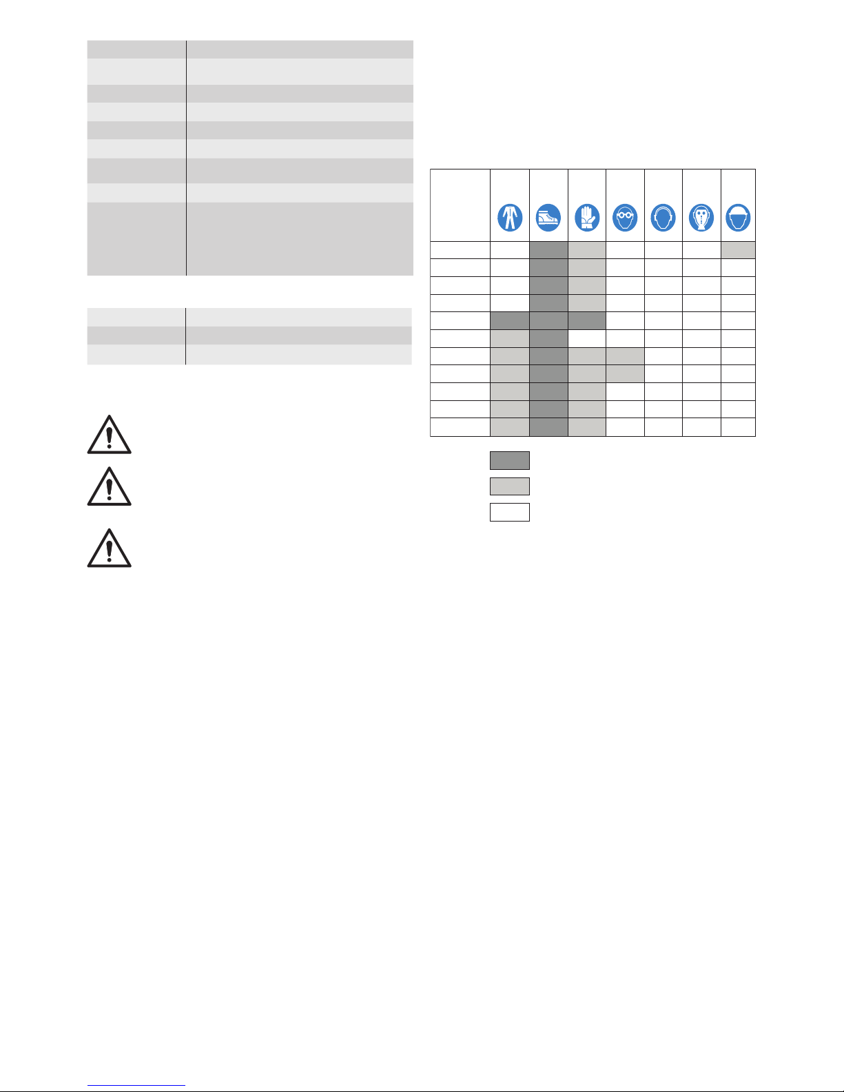
A.1.10 PERSONAL PROTECTION EQUIPMENT
Given below is a summary table of the Personal Protection
Equipment (PPE) to be used during the various stages of the
machine’s service life.
X
Safety
footwear
Protective
garments
Gloves Glasses
Ear
protectors
Mask
Safety
helmet
Stage
Transport
Handling
Unpacking
Assembly
Normal use
Adjustments
Routine
cleaning
Extraordinary
cleaning
Maintenance
Dismantling
Scrapping
X
X
X
X
X
X (*)
X
X (*)
X
X
X
X
X
X
Key:
X
PPE REQUIRED
PPE AVAILABLE OR TO BE USED IF NECESSARY
PPE NOT REQUIRED
(*) During Normal use, gloves protect hands from the cold tray
when being removed from the appliance.
NOTE: The gloves to be worn during Cleaning are the type
suitable for contact with the cooling ns (metal plates).
Failure to use the personal protection equipment by operators,
specialised technicians or users can involve exposure to chemical
risk and possible damage to health.
A.1.11 KEEPING THE MANUAL
The manual must be carefully kept for the entire life of the
machine, until scrapping.
The manual must stay with the machine in case of transfer, sale,
hire, granting of use or leasing.
A.1.12 RECIPIENTS OF THE MANUAL
This manual is intended for:
• the carrier and handling personnel;
• installation and commissioning personnel;
• the employer of machine users and the workplace manager;
• operators for normal machine use;
• specialised technicians - after-sales service (see service
manual).
Page 4

30
A.2 TECHNICAL DATA
A.2.1 MATERIALS AND FLUIDS USED
The areas in contact with the product are in steel or coated
with non-toxic plastic material. An HFC (R134a(GWP:1430)/
R404a(GWP:3922)) refrigerant uid complying with the current
regulations is used in the refrigeration units. The type of refrigerant
gas used is given on the dataplate.
A.2.2 DIMENSIONS, PERFORMANCE AND CONSUMPTION
REFRIGERATED MODELS
Capacity 2 compartments 3 compartments 4
compartments
External dimensions:
- width mm 1236 1720 2203
- depth: mm 700 700 700
door open mm 1101 1101 1101
drawers open mm 1251 1251 1251
- height: mm 850 850 850
with splashback mm 950 950 950
Compartment dimen sions :
- width mm 365X2 365X3 365X4
- depth mm 580 580 580
- height mm 543 543 543
Rack dimensions mm 325X530 325X530 325X530
Power
supply voltage V/ph/Hz. 230/1+N/50 230/1+N/50
Equivalent sound pressure level Leq (*) dB(A) <70
(*) The value could increase depending on the workplace where
measured.
Negative temperature counters
2 compartments
Weight kg 87
Temp. range in compartment °C -2/+10
Max. room temp era ture °C +43
3 compartments
Weight kg 126
Temp. range in compartment °C -2/+10
Max. room temp era ture °C +43
4 compartments
Weight kg 151
Temp. range in compartment °C -2/+10
Max. room temp era ture °C +43
Negative temperature counters
(arranged for remote unit)
Capacity 2 compartments 3 compartments 4
compartments
External dimensions:
- width mm 1106 1590 2073
- depth: mm 700 700 700
door open mm 1101 1101 1101
drawers open mm 1251 1251 1251
- height: mm 850 850 850
with splashback mm 950 950 950
Compartment dimen sions :
- width mm 365X2 365X3 365X4
- depth mm 580 580 580
- height mm 543 543 543
Rack dimensions mm 325X530 325X530 325X530
2 compartments
Weight kg 87
Temp. range in compartment °C -2/+10
Max. room temp era ture °C +43
3 compartments
Weight kg 126
Temp. range in compartment °C -2/+10
Max. room temp era ture °C +43
4 compartments
Weight kg 151
Temp. range in compartment °C -2/+10
Max. room temp era ture °C +43
- Recommended condensing unit for counter 2/3
compartments
model CML60TB3N
Power supply voltage V/ph/Hz. 230/1+N/50
Refrigerant used type R404a
Thermostatic valve (DANFOSS) type 067U2076
- Recommended condensing unit for counter 4
compartments
model CML80TB3N
Power supply voltage V/ph/Hz. 230/1+N/50
Refrigerant used type R404a
Thermostatic valve (DANFOSS) type 067U2076
FREEZER MODELS
Ca pa ci ty 2 compartments 3
compartments
External dimensions
-width mm 1234 1718
-depth mm 700 700
door open mm 1098 1098
drawers open mm 1245 1245
-height mm 850 850
Compartment di men sions
-width mm 365X2 365X3
-depth mm 580 580
-height mm 543 543
Rack dimensions mm 325X530 325X530
Power
supply voltage V/ph/Hz. 230/1+N/50 230/1+N/50
Equivalent sound pressure level Leq (*) dB(A) <70
(*) The value could increase depending on the workplace where
measured.
Counter with 2 doors
Weight kg 145
Temp. range in compartment °C -20/-15
Max. room temp era ture °C +43
Counter with 1 door and 2 ½ drawers
Weight kg 150
Temp. range in compartment °C -20/-15
Max. room temp era ture °C +43
Counter with 3 doors
Weight kg 216
Temp. range in compartment °C -20/-15
Max. room temp era ture °C +43
Counter with 2 doors and 2 ½ drawers
Weight kg 221
Temp. range in compartment °C -20/-15
Max. room temp era ture °C +43
A.2.2.1 CLIMATIC CLASS
The climatic class given on the dataplate refers to the following
values:
5 (or 7) = 43°C (IEC/EN 60335-2-89)
5 = 40°C room temp. with 40% relative humidity (IEC/EN ISO
23953)
7 = 35°C room temp. with 75% relative humidity (IEC/EN ISO
23953)
Page 5
31
B.1 TRANSPORT, HANDLING AND STORAGE
B.1.1 INTRODUCTION
Transport (i.e. transfer of the machine from one place to another)
and handling (i.e. transfer inside workplaces) must occur with the
use of special and adequate means.
ATTENTION!
Due to their size, the machines cannot be stacked
on top of each other during transport, handling
and storage; this eliminates any risks of loads
tipping over due to stacking.
The machine must only be transported, handled and stored by
qualied personnel, who must:
- have specic technical training and experience in the use of
lifting systems;
- have knowledge of the safety regulations and applicable laws
in the relevant sector;
- have knowledge of the general safety rules;
- ensure the use of personal protection equipment suitable for
the type of operation carried out;
- be able to recognise and avoid any possible hazard.
B.1.2 TRANSPORT: INSTRUCTIONS FOR THE CARRIER
ATTENTION!
Do not stand under suspended loads during load-
ing/unloading operations.
Unauthorised personnel must not enter the work
area.
ATTENTION!
The machine’sweightaloneis not sufcient to
keep it steady. The transported load can shift:
- when braking;
- when accelerating;
- in corners;
- on rough roads.
B.1.3 HANDLING
Arrange a suitable area with at oor for machine unloading and
storage operations.
B.1.4 PROCEDURES FOR HANDLING OPERATIONS
For correct and safe lifting operations:
• use the type of equipment most suitable for characteristics
and capacity (e.g. electric pallet truck or lift truck);
• cover sharp edges;
Before lifting:
• send all operators to a safe position and prevent persons
from entering the handling area;
• make sure the load is stable;
• make sure no material can fall during lifting. Manoeuvre vertically in order to avoid impacts;
• handle the machine, keeping it at minimum height from the
ground.
ATTENTION!
For machine lifting, do not use movable or weak
parts such as: casings, electrical raceways, pneumatic parts, etc.
ATTENTION!
For information regarding weight, packing and
handling of the remote unit, refer to the manufacturer’s instructions.
B.1.5 TRANSLATION
The operator must:
• have a general view of the path to be followed;
• stop the manoeuvre in case of hazardous situations.
ATTENTION!
Do not push or pull the appliance to move it, as it
may tip over.
B.1.6 PLACING THE LOAD
Before placing the load, make sure the way is free and that the
oor is at and can take the load. Remove the appliance from
the wooden pallet, move it to one side, then slide it onto the oor.
B.1.7 STORAGE
The machine and/or its parts must be stored and protected against
damp, in a non-aggressive place free of vibrations and with room
temperature between -10°C and 50°C.
The place where the machine is stored must have a at support
surface in order to avoid any twisting of the machine or damage
to the support feet.
ATTENTION!
Machine positioning, installation and disassembly
must be carried out by a specialised technician.
ATTENTION!
Donotmakemodicationstothepartssupplied
with the machine. Any missing or faulty parts must
be replaced with original parts.
B.2 INSTALLATION AND ASSEMBLY
To ensure correct operation of the appliance and maintain safe
conditions during use, carefully follow the instructions given
below in this section.
ATTENTION!
The operations described below must be carried
out in compliance with the current safety regulations, regarding the equipment used and the operating procedures.
ATTENTION!
Before moving the appliance make sure the load
bearing capacity of the lifting equipment to be
used is suitable for its weight.
B.2.1 THE CUSTOMER’S RESPONSIBILITIES
The Customer must:
- provide an earthed power socket of suitable capacity for the
input specied on the dataplate;
- provide a high sensitivity manual-reset differential thermalmagnetic switch. For information regarding the electrical
connection, refer to par. B.2.8 “Electrical connection”;
- check the atness of the surface on which the machine is
placed.
B.2.2 MACHINE SPACE LIMITS
A suitable space must be left around the machine (for operations,
maintenance, etc.). This space must be increased in case of use
and/or transfer of other equipment and/or means or if exit routes
are necessary inside the workplace. Make sure to position the
appliance at least 50 mm from any other machines present in the
room (in fact, close proximity can create problems of condensate
forming on the walls of the appliance), also taking into consideration
the space needed for door opening.
B.2.3 POSITIONING
Install the appliance, taking all the safety precautions required for
this type of operation, also respecting the relevant re-prevention
instructions.
Install the appliance in a ventilated place, away from heat sources
such as radiators or air conditioning systems, to allow correct
cooling of the refrigeration unit components. Never cover the
condenser, even temporarily, as this can compromise correct
operation of the appliance. If the machine is installed in a place
where there are corrosive substances (chlorine, etc.), it is advisable
to go over all the stainless steel surfaces with a rag soaked in
parafn oil in order to create a protective lm. The appliances
maintain their performance characteristics at a room temperature
of +43°C; in any case the max. room temperature at which they
Page 6
32
can operate is +43°C.
The machine must be taken to the place of installation and the
packing base removed only when being installed.
Arranging the machine:
• position the machine in the required place;
• adjust the height and levelling with the adjustment feet, also
checking correct door and drawer closing:
ATTENTION!
The appliance must be levelled; otherwise its
operation could be affected.
NOTE:
The plug must be accessible even after the appliance
is positioned in the place of installation.
• wear protective gloves and unpack the machine, carrying out
the following operations:
- cut the straps and remove the protective lm, taking care
not to scratch the surface if scissors or blades are used;
- remove the cardboard top, the polystyrene corners and
the vertical protection pieces.
For appliances with stainless steel cabinet, remove the protective
lm very slowly without tearing it, to avoid leaving glue stuck to
the surface. Should this happen, remove the traces of glue with
a non-corrosive solvent, rinsing it off and drying thoroughly; it is
advisable to go over all the stainless steel surfaces with a rag
soaked in parafn oil in order to create a protective lm.
B.2.4 DISPOSAL OF PACKING
The packing must be disposed of in compliance with the current
regulations in the country where the appliance is used.
All the packing materials are environmentally friendly. They can be
safely kept, recycled or burnt in an appropriate waste incineration
plant. Recyclable plastic parts are marked as follows:
PE
polyethylene: outer wrapping, instruction
booklet bag
PP
polypropylene: straps
PS
polystyrene foam: corner protectors
The parts in wood and cardboard can be disposed of, respecting
the current regulations in the country where the machine is used.
ATTENTION: With remote versions, connect the appliance to
the drainage system for the defrost water (kits with automatic
condensate evaporation are available).
B.2.5 POSITIONING MODELS FOR USE WITH REMOTE UNITS
ATTENTION!
Installation of the appliance and the refrigerant
condensing unit must only be carried out by the
manufacturer’s service personnel or by a specialised technician.
Place the condensing unit in a well-ventilated room away from
heat sources.
If the remote unit is installed outdoors, it must be protected against
the action of atmospheric agents with adequate covering, in any
case ensuring correct ventilation of the condensing unit.
Choose pipe widths according to that given in the technical data
(for recommended units).
Lay the copper piping, choosing the shortest path and avoiding
bends, elbows and vertical sections as much as possible, keeping
to the following:
- in horizontal sections, the inlet line must slope down towards
the condensing unit at an angle of not less than 2%;
- traps must be installed before all upward sections of the inlet
line, at a distance of 3-3.5 metres from each other;
- insulate the inlet line with suitable lagging;
- it is advisable to install the remote unit at a max. pipe length
of between 15 m and 20 m from the appliance.
NOTE: If the distance exceeds 20 m, ask the technical depart-
ment for details or use a more powerful refrigeration unit.
• Install on the delivery line, in the following order: a suitably
sized dehydration lter, a liquid ow indicator and a solenoid
valve, if not present.
B.2.6 EVACUATING THE LINES AND CHARGING WITH
REFRIGERANT GAS
(for installation with remote refrigeration unit)
ATTENTION!
CHARGING WITH REFRIGERANT MUST BE DONE
BY PROFESSIONALLY QUALIFIED PERSONNEL.
B.2.6.1 Leakage test
- Wash the inlet and delivery pipes with pressurised dry nitrogen;
- connect a nitrogen cylinder to the high and low pressure connectors, making sure to also install a pressure gauge (using
a “T” union), and charge the high and low pressure lines with
gas to a pressure of approx. 15 bar. Close the cylinder cock
and, after at least 1 hour, check that the pressure has not
dropped below the previous reading value.
B.2.6.2 Vacuum
- Empty the circuit manually by opening the cocks on the unions;
- connect the pipes to a vacuum pump (preferably a two-stage
model with vacuum gauge and high and low pressure connectors). Reach a vacuum level equal to or lower than 70mTorr
(0.0931 mbar). On reaching this level, maintain it for about 15
minutes and then proceed with charging the unit as described
below.
B.2.6.3 Charging with refrigerant
- Charge the high pressure (HP) line with liquid refrigerant for
R404A (to ensure addition of the correct mixture) until bringing
the pressure above 0 bar (atmospheric pressure);
- then shut off the high pressure (HP) line, start the compres-
sor and charge with liqueed gas slowly with short impulses
from the low pressure (LP) line until the bubbles in the liquid
indicator disappear, being careful not to freeze the inlet pipe
(LP) near the compressor.
B.2.7 CHECKS WHEN STARTING UP THE APPLIANCE
Check on the liquid ow indicator that the circuit is sufciently
charged. Otherwise, complete charging following the instructions
in § B.2.6.3.
Using a digital thermometer, check that the temperature reading
on the control panel matches the instrument reading.
B.2.8 ELECTRICAL CONNECTION
Connection to the power supply must be carried out in compliance
with the regulations and provisions in force in the country of use.
ATTENTION!
Work on the electrical systems must only be car-
riedoutbyaqualiedelectrician.
The ap pliance works on a single phase 230V 50Hz power supply .
To connect to the power supply, in sert the power cable plug in
the corr esponding mains so cket , rstmakingsure:
- the so cket has an ef ci ent earth contact and the mai ns voltage
and frequency match that given on the dataplate. In case of
any doubts regarding the efciency of the earth connection
have the system checked by qualied personnel;
- the system power supply is arranged and able to take the
actual current absorption and that it is correctly executed
according to the regulations in force in the country of use;
- a differential thermal-magnetic switch suitable for the input
specied on the dataplate, with contact gap enabling complete disconnection in category III overvoltage conditions and
complying with the regulations in force, is installed between
the power cable and the electric line. For the correct size of
the switch, refer to the absorbed current specied on the appliance dataplate.
Page 7
33
• After making the connection, with the machine running check
that the power supply does not uctuate by ±10% the rated
voltage.
Note: In models arranged for operation with remote units, make
the
electrical connection to the condensing unit and solenoid valve
as shown in the wiring diagram attached to the appliance.
The connection must be made with cable of adequate
section.
If the power cable is damaged, it must be replaced by the
after-salesserviceorinanycasebyqualiedpersonnel,in
order prevent any risk.
The manufacturer declines any liability for damage or injury
resulting from breach of the above rules or non-compliance
with the electrical safety regulations in force in the country
where the machine is used.
B.2.9 ELECTRICAL CONNECTION (ONLY FOR APPLIANCES WITH CABLE WITHOUT PLUG)
Connection to the power supply must be carried out in compliance with the regulations and provisions in force in the country
of use.
ATTENTION!
Work on the electrical systems must only be car-
riedoutbyaqualiedelectrician.
The information regarding the appliance power supply voltage
is given on the dataplate.
Before connecting, make sure:
the connection point has an efcient earth contact and the mains
voltage and frequency match that given on the data plate. In
case of doubts regarding the efciency of the earth wire, have
the system checked by qualied personnel;
the system power supply is arranged and able to take the actual
current absorption and that it is correctly executed according
to the regulations in force in the country of use;
the appliance must be permanently connected to the power
supply, respecting the polarities:
- brown: phase
- yellow/green: earth
- blue: neutral;
a differential thermal-magnetic switch (or plug) suitable for the
absorption specied on the data plate, with contact gap enabling
complete disconnection in category III overvoltage conditions
and complying with the regulations in force, is installed between
the power cable and the electric line. For the correct sizing of
the switch or plug, refer to the absorbed current specied on
the appliance data plate. The chosen device must be lockable
in the open position in case of maintenance.
ATTENTION: When using a plug, it must comply with the
national installation rules. The plug must also be:
accessible after the appliance has been positioned
in the place of installation;
in a position always visible to the operator performing the intervention during maintenance operations.
After making the connection, with the appliance running check
that the power supply does not uctuate by ±10% the rated
voltage.
ATTENTION!
An H05VV-F power cable (designation 60227 IEC
53) is used for the permanent connection to the
power supply; when replacing it, use a type having
at least these characteristics.
ATTENTION!
When replacing the cable, the earth wire must be
kept longer than the live and neutral wires.
If the power cable is damaged, it must be replaced by the
servicecentreorinanycasebyqualiedpersonnel,in
order prevent any risk.
The manufacturer declines any liability for damage or
injury resulting from breach of the above rules or noncompliance with the electrical safety regulations in force
in the country where the machine is used.
ATTENTION: THE DOORS ARE NOT REVERSIBLE.
C.1 CONTROL PANEL
C.1.1 CONTROL PANEL
(see Fig.1)
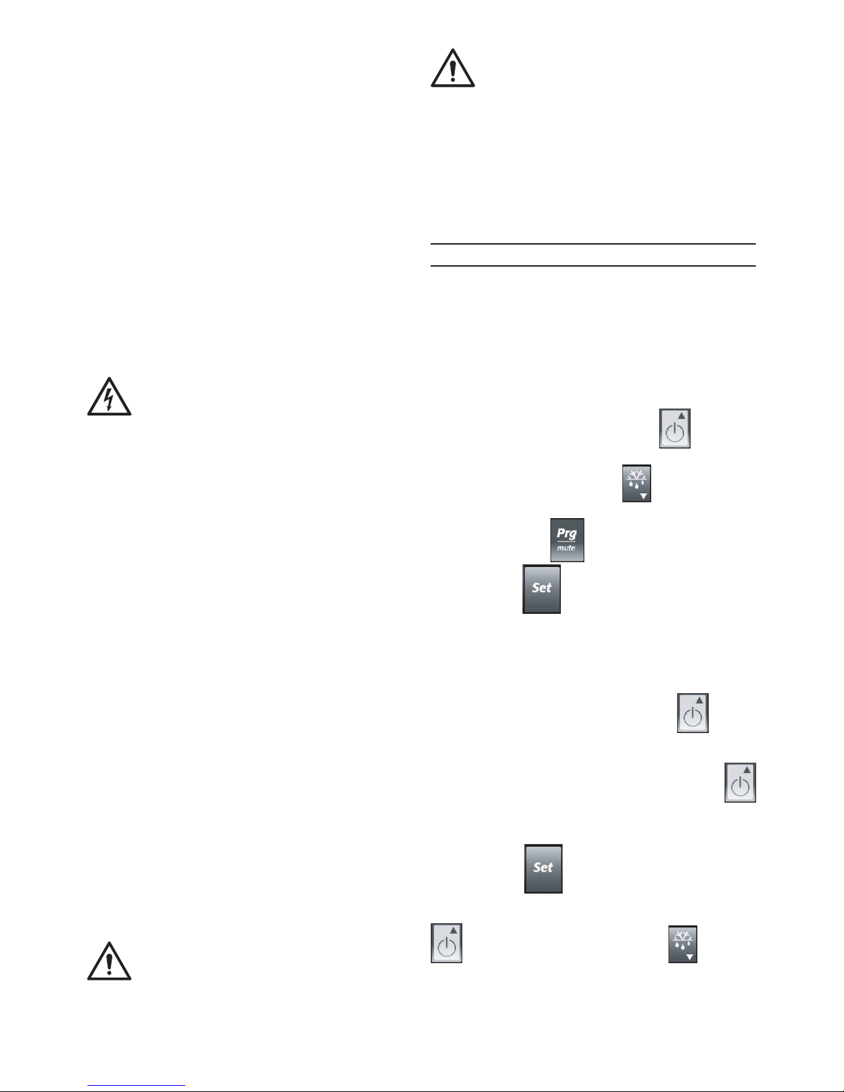
C.1.2 DIGITAL THERMOSTAT DISPLAY
The digital thermostat has a 3-digit electronic display for showing
the temperature measured by the probe, and six ICONS (see
g.1 and par. C.1.5).
C.1.3 BUTTONS
The digital thermostat has 4 buttons for control and programming
the instrument.
- Multifunction “ON/OFF” and “UP” button for switching
the appliance on or off and increasing the values.
- “DOWN” and “DEFROST” button for activating manual
defrost and decreasing the values.
- “Prg/mute” button for silencing the alarm buzzer.
- “SET” button for accessing the Set point.
C.1.4 SWITCHING ON AND TEMPERATURE ADJUSTMENT
When switched on, the instrument performs a Lamp Test, i.e.
for a few seconds the display and Icons ash, verifying its
correct functioning. If the instrument displays the compartment
temperature when switched on, the appliance is already on; if
“OFF” is displayed, press the “ON/OFF” button for a few
seconds to activate the appliance; the display shows the message
“ON” and then the compartment temperature.
To switch the appliance off, press the “ON/OFF” button
for a few seconds ; the message “OFF” appears on the display.
To SET the compartment temperature, proceed as follows:
- Press the button for a few seconds and theSET POINT
value appears on the display.
- To change the SET value, press the “UP” increase value button
or the “DOWN” decrease value button .
If no button is pressed for 60 seconds (“TIME OUT”), or by
pressing the “SET” button once, the digital thermostat memorises
the last set value and the normal display is restored.
The temperature range is set from a
minimum to a maximum, according to the following values:
Page 8
34
Maximum pos. = - 2 °C
Minimum pos. = + 10 °C
Maximum pos. = - 15°C
Minimum pos. = - 20°C
C.1.5 DIGITAL THERMOSTAT ICONS
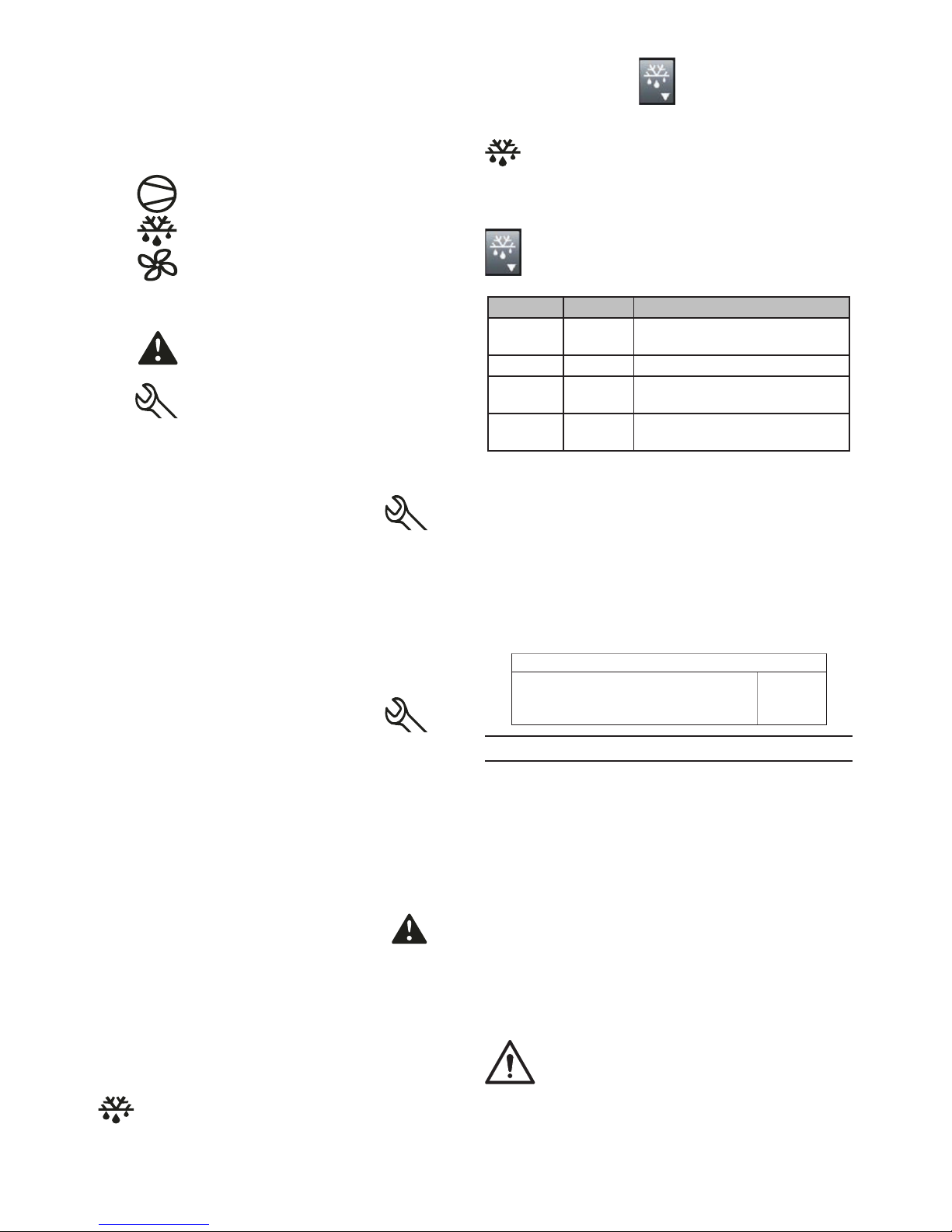
The digital thermostat has 5 signalling ICONS:
- Icon lit up indicates compressor activation.
- Icon lit up indicates manual defrost in progress.
- Icon lit up indicates activation of compartment fans (if
present).
- Icon “aux” lit up indicates activation of auxiliary users (if
present).
- Icon indicates that a temperature alarm has occurred
during appliance operation.
- Icon indicates that a service alarm has occurred during
appliance operation.
C.1.6 ALARMS AND SIGNALLING
C.1.6.1 Service alarms and signalling for models
0°C/+10°C
The alarm is signalled by lighting up of the Icon alarm
signalling is also indicated by the alarm code appearing on the
display.
Example: Alarm signalling due to a faulty probe (compartment
probe) appears directly on the instrument display with the
message “E0” and “rE” ashing alternately (refer to position 1
of the alarms table).
When the alarm condition ceases, the alarm goes off. Otherwise,
contact the After-Sales Service.
C.1.6.2 Signalling alarms for models -15°C/-22°C and
-2°C/+10°C
The alarm is signalled by lighting up of the Icon alarm
signalling is also indicated by the alarm code appearing on the
display.
Example: Alarm signalling due to a faulty probe (compartment
probe) appears directly on the instrument display with the
message “E0” and “rE” ashing alternately (refer to position 1
of the alarms table).
Alarm signalling due to a faulty evaporator probe (evaporator
probe) appears directly on the instrument display with the indication
“E1” ashing (refer to position 2 of the alarms table).
C.1.6.3 Temperature alarms and signalling (common to all
appliances)
The alarm is signalled by lighting up of the Icon alarm
signalling is also indicated by the alarm code appearing on the
display.
Temperature alarm signalling, regarding the thermostatting probe,
appears directly on the instrument display with the indication “HI”
(max. temperature alarm) and “LO” (min. temperature alarm).
C.1.7DEFROST(g.1)
- Automatic defrost
The appliance has an automatic defrost function.
This function is signalled by lighting up of the DEFROST icon
.
Thedefrost water is run into a tray and automatically evaporated.
- Manual defrost activation
Keep the “DOWN” button pressed for at least 5 seconds
to start a manual defrost cycle.
This function is signalled by lighting up of the DEFROST icon
.
If defrost conditions do not exist, the display shows the message
“dFb”, indicating that the operation will not be carried out (only
for models -15°C/-22°C and -2°C/+10°C).
Defrost can be stopped manually by pressing the “DOWN” button
for a few seconds the display shows the message “dFE”.
Defrost cannot be activated in the programming stage.
POSITION DISPLAY ALARM
1 E0/rE
Compartment probe fault
alarm
2 E1 Evaporator probe fault alarm
3 HI
Compartment high
temperature alarm
4 LO
Compartment low temperature
alarm
C.1.8 LOADING THE PRODUCT
Distribute the product evenly inside the compartment (away from
the door, back and side walls) in order to ensure good air circulation.
Co ver or wr ap food bef ore pla cing it in the re frige rat or and avoid pu tti ng ve ry hot fo ods or ste am ing liq uids inside. Do not
leave the door open any longer than necessary when loading
or removing food.
Keep the keys out of reach of children.
Regarding the max. load for each shelf, respect that given in the
table below:
MAX. LOAD FOR PAN
HORIZONTAL
REFRIGERATORS WITH
DIGITAL CONTROL
40 Kg
C.3 GENERAL SAFETY RULES
C.3.1 INTRODUCTION
The machines are provided with electric and/or mechanical safety
devices for protecting workers and the machine itself. Therefore
the user must not remove or tamper with such devices.
The Manufacturer declines any liability for damage due to
tampering or their non-use.
C.3.2 PROTECTION DEVICES INSTALLED ON THE MACHINE
C.3.2.1 Guards
The guards on the machine are:
- xed guards (e.g. casings, covers, side panels, etc.), xed
to the machine and/or frame with screws or quick-release
connectors that can only be removed or opened with tools;
- interlocked movable guards (front panels) for access inside
the machine;
- machine electrical equipment access doors, made from
hinged panels openable with tools. The door must not be
opened when the machine is connected to the power supply.
ATTENTION!
Several illustrations in the manual show the ma-
chine, or parts of it, without guards or with guards
removed. This is purely for explanatory purposes.
Do not use the machine without the guards or with
the protection devices deactivated.
Page 9
35
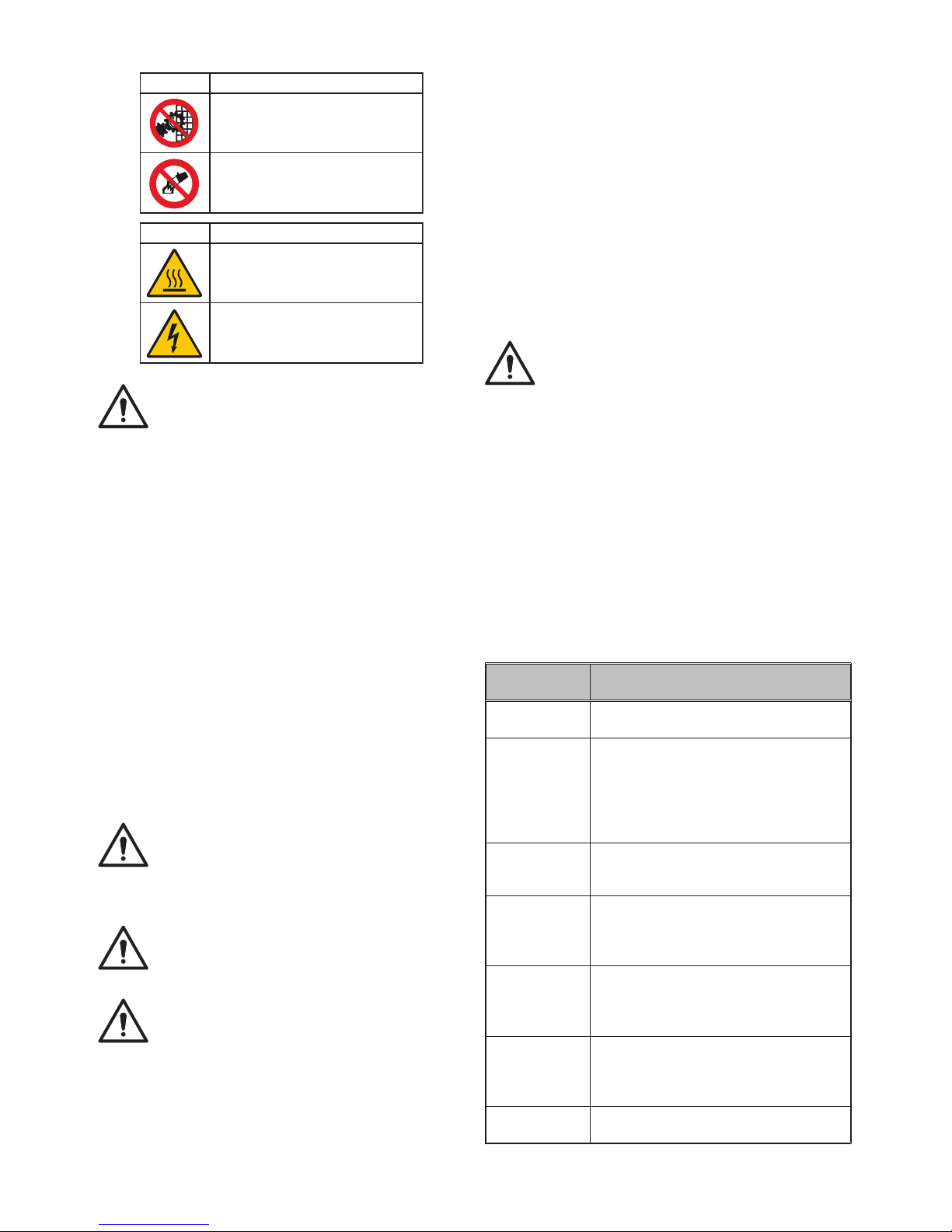
C.3.3 SAFETY SIGNS TO BE PLACED ON THE MACHINE OR
NEAR ITS AREA
PROHIBITION
Do not remove the safety
devices.
Do not use water
to extinguish fires (shown on
electrical parts).
DANGER OF BURNS.
DANGER OF ELECTROCUTION
(shown on electrical parts with
indication of voltage).
DANGER MEANING
MEANING
ATTENTION!
Do not remove, tamper with or make illegible the
safety, danger and instruction signs and labels
on the machine.
C.3.4 END OF USE
When the appliance is no longer to be used, make it unusable
by removing the power supply wiring.
C.3.5 INSTRUCTIONS FOR USE AND MAINTENANCE
Risks mainly of a mechanical, thermal and electrical nature are
present in the machine.
Where possible the risks have been neutralised:
• directly, by means of adequate design solutions,
• indirectly by using guards, protection and safety devices.
Any anomalous situations are signalled on the control panel
display.
During maintenance several risks remain, as these could not
be eliminated, and must be neutralised by adopting specic
measures and precautions.
Do not carry out any checking, cleaning, repair or maintenance
operations on moving parts.
Workers must be informed of the prohibition by means of clearly
visible signs. To guarantee machine efciency and correct
operation, periodical maintenance must be carried out according
to the instructions given in this manual. In particular, make sure
to periodically check correct operation of all the safety devices
and the insulation of electrical cables, which must be replaced
if damaged.
ATTENTION!
Machine maintenance operations must only be
carried out by specialised Technicians provided
with all the appropriate personal protection equipment (safety shoes, gloves, glasses, overalls,
etc.), tools, utensils and ancillary means.
ATTENTION!
Never operate the machine, removing, modifying
or tampering with the guards, protection or safety
devices.
ATTENTION!
Before carrying out any operation on the machine,
always consult the manual which gives the correct
procedures and contains important information
on safety.
C.3.6 REASONABLY FORESEEABLE IMPROPER USE
Improper use is any use different from that specied in this
manual. During machine operation, other types of work or
activities deemed improper and that in general can involve risks
for the safety of operators and damage to the appliance are not
allowed.
Reasonably foreseeable improper use includes:
• lack of machine maintenance, cleaning and periodical checks;
• structural changes or modications to the operating logic;
• tampering with the guards or safety devices;
• failure to use personal protection equipment by operators,
specialised technicians and maintenance personnel;
• failure to use suitable accessories (e.g. use of unsuitable
equipment or ladders);
• keeping combustible or ammable materials, or in any case
materials not compatible with or pertinent to the work, near
the machine;
• wrong machine installation;
• placing in the machine any objects or things not compatible
with refrigeration, freezing or preservation, or that can damage the machine, cause injury or pollute the environment;
• climbing on the machine;
• non-compliance with the requirements for correct machine
use;
• other actions that give rise to risks not eliminable by the
Manufacturer.
ATTENTION!
The previously described actions are prohibited!
C.3.7 RESIDUAL RISKS
The machine has several risks that were not completely
eliminated from a design standpoint or with the installation of
adequate protection devices.
Nevertheless, through this manual the Manufacturer has taken
steps to inform operators of such risks, carefully indicating the
personal protection equipment to be used by them.
Sufcient spaces are provided for during the machine installation
stages in order to limit these risks.
To preserve these conditions, the areas around the machine
must always be:
• kept free of obstacles (e.g. ladders, tools, containers, boxes,
etc.);
• clean and dry;
• well lit.
For the Customer’s complete information, the residual risks
remaining on the machine are indicated below: such actions are
to be considered incorrect and therefore strictly forbidden.
RESIDUAL RISK
DESCRIPTION OF HAZARDOUS
SITUATION
Slipping or falling
The operator can slip due to water or dirt on
the oor.
Burns/abrasions
(e.g. heating
elements, cold
tray, cooling
circuit plates and
pipes)
The operator deliberately or unintentionally
touches some components inside the
machine without using protective gloves.
Electrocution
Contact with live parts during maintenance
operations carried out with the electrical
panel powered.
Falling from
above
The operator works on the machine using
unsuitable systems to access the upper part
(e.g. rung ladders, or climbs on it).
Crushing or injury
The specialised Technician may not
correctly x the control panel when
accessing the technical compartment. The
panel could close suddenly.
Tipping of loads
When handling the machine or the packing
containing it, using unsuitable lifting systems
or accessories or with the load unbalanced.
Chemical
(refrigerant gas)
Inhalation of refrigerant gas. Therefore
always refer to the appliance labels.
Page 10
36
C.4 NORMAL MACHINE USE
C.4.1 CHARACTERISTICS OF PERSONNEL TRAINED FOR
NORMAL MACHINE USE
The Customer must make sure the personnel for normal machine
use are adequately trained and skilled in their duties, as well as
ensuring their own safety and that of other persons.
The Customer must make sure his personnel have understood
the instructions received and in particular those regarding work
hygiene and safety in use of the machine.
C.4.2 CHARACTERISTICS OF PERSONNEL ENABLED TO
OPERATE ON THE MACHINE
The Customer is responsible for ensuring that persons assigned
to the various duties:
• read and understand the manual;
• receive adequate training and instruction for their duties in
order to perform them safely;
• receive specic training for correct machine use.
C.4.3 OPERATOR FOR NORMAL MACHINE USE
He must have at least:
• knowledge of the technology and specic experience in
operating the machine;
• adequate general basic education and technical knowledge
for reading and understanding the contents of the manual;
• including correct interpretation of the drawings, signs and
pictograms;
• sufcient technical knowledge for safely performing his duties
as specied in the manual;
• knowledge of the regulations on work hygiene and safety.
In case of a signicant fault (e.g. short circuits, wires coming out
of the terminal block, motor breakdowns, worn electrical cable
sheathing, etc.) the operator for normal machine use must:
• immediately deactivate the machine.
D.1 MACHINE CLEANING AND
MAINTENANCE
ATTENTION!
Before carrying out any cleaning or maintenance
operation, disconnect the appliance from the
power supply and carefully unplug it.
Disconnect the appliance from the power supply at
least 30 minutes before carrying out any cleaning
or maintenance operation.
ATTENTION!
During maintenance, the cable and plug must be
kept in a visible position by the operator carrying
out the work.
ATTENTION!
Do not touch the appliance with wet hands or
feet or when barefoot. Do not remove the safety
guards.
ATTENTION!
Use suitable personal protection equipment (pro-
tective gloves).
D.1.1 ROUTINE MAINTENANCE
ATTENTION!
Disconnect the power supply before cleaning the
appliance.
D.1.1.1 Precautions for maintenance
Routine maintenance operations can be carried out by nonspecialised personnel, carefully following the instructions
given below. The manufacturer declines any liability for
operations carried out on the machine without following
these instructions.
D.1.1.2 Cleaning the cabinet and accessories
Be fo re us ing the appli ance, cl e an all the in si de pa rts an d ac cessor ies wi th lukewa rm wa ter an d ne ut ral so ap or pr odu cts th at
are over 90% bio degra dable (in order to reduce the emission of
pollutants into the envi ronment), then rinse and dry thoroughly.
Do not use so lvent-based deter gents (e.g. tri chl oro-ethylene) or
abrasive powders for cleaning.
It is advisable to go over the stainless steel surfaces with a rag
moistened with parafn oil in order to create a protective lm.
Check the power cable regularly and replace it in case of signs
of wear.
Have the appliance checked periodically (at least once a year).
ATTENTION!
Do not clean the machine with jets of water.
ATTENTION!
Do not use steel wool or similar material to clean
stainless steel surfaces. Do not use detergents
containing chlorine, solvent-based detergents
(e.g. trichloro-ethylene) or abrasive powders.
D.1.1.3 Compartment cleaning
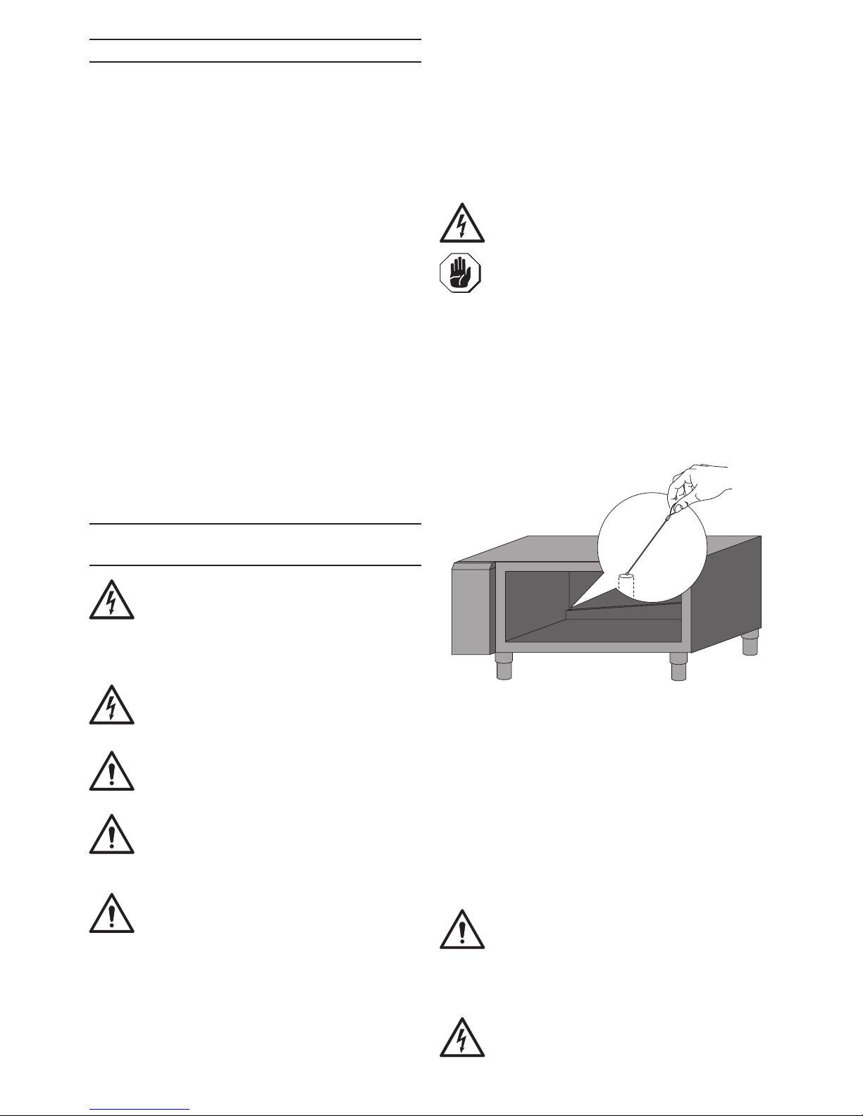
To clean the com partment, remove all the racks, remove the
screws xing the wire structures, clean the compartment with
products that are over 90% bio deg rable, th en rin se and dry thoro ug hly .
ATTENTION: These appliances do not have a water drain hole.
For refrigerated models: periodically clean the defrost water
drain hole (located on the back of the compartment) by
means of the “swab” provided, it order to clear the hole if
clogged(seegurebelow)
ATTENTION! After cleaning, do not leave the “swab” in the
drain hole.
NOTE: This operation cannot be carried out on freezer
models.
D.1.1.4 Precautions in case of long idle periods
If the ap pli an ce is not go ing to be us ed for so me ti me, ta ke the
fo ll ow ing precautions:
• unplug it ;
• remove all food from the compartment and clean the inside
and accessories;
• le ave the do or aj ar so th at a ir can ci rc ul ate in si de, pr even ti ng
th e fo rm at ion of un pl ea sant odours;
• a ir th e premises p e ri od ic al ly.
ATTENTION!
Machine maintenance, checking and overhaul op-
erations must only be carried out by a specialised
Technician or the After-Sales Service, provided
with adequate personal protection equipment
(safety shoes and gloves), tools and ancillary
means.
ATTENTION!
Work on the electrical equipment must only be
carried out by a specialised electrician or the
After-Sales Service.
Page 11
37
ATTENTION!
Put the machine in safe conditions before starting
any maintenance operation.
After carrying out maintenance make sure the machine is able
to work safely and, in particular, that the protection and safety
devices are efcient.
ATTENTION!
Respect the requirements for the various routine
and extraordinary maintenance operations.
Non-compliance with the instructions can create
risks for personnel.
D.1.2 EXTRAORDINARY MAINTENANCE
ATTENTION!
WEAR PROTECTIVE GLOVES AND A MASK WHEN
CARRYING OUT ANY EXTRAORDINARY MAINTENANCE OPERATIONS.
Extraordinary maintenance must be carried out by
specialised personnel, who can ask the manufacturer to
supply a servicing manual.
D.1.2.1 Periodical condenser cleaning
For the appliance to work efciently, the refrigeration unit
condenser lter, located under the control panel, must be cleaned
at least once every 3 months.
If the appliance is installed in a dusty or poorly ventilated place,
the condenser lter must be cleaned more frequently, about
once a month.
Note: It is advisable to use a brush or vacuum cleaner to remove
the dirt accumulated on the lter.
ATTENTION!
Do not clean the appliance with jets of water.
D.1.2.2 Replacing the power cable
To replace the power cable, proceed as follows:
• Disconnect the power supply;
• Remove the electrical system guard;
• Replace the power cable;
• Ret the guard;
• Reconnect the power supply.
D.1.2.3 Quick troubleshooting guide
In some cases, faults can be eliminated easily and quickly; The
following is a list of possible problems with their solutions:
A. The appliance does not switch on:
- make sure the plug is properly inserted in power socket.
- make sure the socket is powered.
B. The inside temperature is too high:
- check the thermostat setting;
- make sure there is no heat source near the appliance;
- make sure the door closes properly.
C. The appliance is too noisy:
- make sure the appliance is properly levelled.An
unbalanced position can set off vibrations.
- make sure the appliance is not touching other appliances
or parts which could reverberate.
D. Water in the compartment:
- make sure the drain is clean. If necessary, clean it by
following the instructions given in par. D.1.1.3.
If the fault persists after carrying out the above checks, contact
the After-Sales Service, remembering to give the following details:
• the type of fault;
• the appliance PNC (production number code);
• the Ser. No. (appliance serial number).
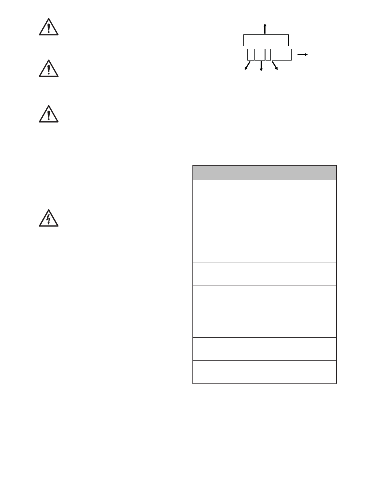
Note: The code and serial number are essential for
identifying the type of appliance and date of manufacture:
appliance identication code
fourth digit of the year
of production (2015)
third digit of the year
of production (2015)
week
50
10th piece
produced
in the week
Ser. No. 5 50 1 0010
PNC
728304 23
D.1.3 MAINTENANCE INTERVALS
The inspection and maintenance intervals depend on the actual
machine operation conditions and ambient conditions (presence
of dust, damp, etc.), therefore precise time intervals cannot be
given. In any case, to minimise interruptions of the service, careful
and periodical machine maintenance is advisable.
It is advisable to stipulate a preventive and scheduled
maintenance contract with the after-sales service.
D.1.3.1 Maintenance frequency
In order to guarantee constant machine efciency, it is advisable to
carry out the checks with the frequency given in the following table:
MAINTENANCE, INSPECTIONS, CHECKS
AND CLEANING
FREQUENCY
Routine cleaning
Daily
General cleaning of machine and surrounding
area
Mechanical protection devices
Monthly
Check condition, and for any deformation,
loosening or removed parts.
Control
Yearly
Check mechanical part, for any breakage
or deformation, tightening of screws. Check
readability and condition of words, stickers and
symbols and restore if necessary.
Machine structure
Yearly
Tightening of main bolts (screws, xing
systems, etc.) of machine.
Safety signs
Annuale
Check readability and condition of safety signs.
Electrical control panel
Yearly
Check electrical components installed inside
the Electrical Control Panel. Check wiring
between the Electrical Panel and machine
parts.
Electrical connection cable and plug
Yearly
Check connection cable (replace it if
necessary) and plug.
Extraordinary machine maintenance
Every 10
years (*)
Check all components, electrical equipment,
corrosion, pipes, ……
(*) the machine is designed and built for a duration of about 10
years. After this period of time (from machine commissioning)
the machine must undergo a general inspection and overhaul.
Some examples of checks to be carried out are given below.
- check for any oxidised electrical components or parts; if
necessary, replace them and restore the initial conditions;
- check the structure and welded joints in particular;
- check and replace bolts and/or screws, also checking for any
loose components;
- check the electrical and electronic system;
- check the functionality of safety devices;
- check the general condition of protection devices and guards.
Page 12
38
ATTENTION!
Machine maintenance, checking and overhaul op-
erations must only be carried out by a specialised
Technician or the After-Sales Service, provided
with adequate personal protection equipment
(safety shoes and gloves), tools and ancillary
means.
ATTENTION!
Work on the electrical equipment must only be
carried out by a specialised electrician or the
After-Sales Service.
D.1.4 DISASSEMBLY
If the appliance has to be disassembled and then reassembled,
make sure the various parts are assembled in the correct order
(if necessary mark them during disassembly).
Before disassembling the machine, make sure to carefully check
its physical condition, and in particular any parts of the structure
that can give or break. Before starting disassembly:
- remove all the pieces (if present) in the machine;
- disconnect the power supply;
- enclose the work area;
- place a sign on the Main Electrical Panel indicating that the
machine is undergoing maintenance and not to carry out
manoeuvres;
- carry out the disassembly operations.
ATTENTION!
All scrapping operations must occur with the ma-
chine stopped and cold and the electrical power
supply disconnected.
ATTENTION!
Work on the electrical equipment must only be car-
riedoutbyaqualiedelectrician,withthepower
supply disconnected.
ATTENTION!
To carry out these operations, appropriate PPE
must be used.
ATTENTION!
During disassembly and handling of the various
parts,theminimumheightfromtheoormustbe
maintained.
D.1.5 DECOMMISSIONING
If the machine cannot be repaired, carry out the decommissioning
operations, signalling the failure with a suitable sign, and request
assistance of the manufacturer’s after-sales service.
D.2 MACHINE DISPOSAL
ATTENTION!
DISMANTLING OPERATIONS MUST BE CARRIED
OUT BY QUALIFIED PERSONNEL.
ATTENTION!
WORK ON THE ELECTRICAL EQUIPMENT MUST
ONLY BE CARRIED OUT BY A QUALIFIED ELECTRICIAN, WITH THE POWER SUPPLY DISCONNECTED.
D.2.1 WASTE STORAGE
At the end of the product’s life-cycle, make sure it is not dispersed
in the environment. The doors must be removed before scrapping
the appliance.
Special waste materials can be stored temporarily while awaiting
treatment for disposal and/or permanent storage. In any case,
the current environmental protection laws in the country of use
must be observed.
D.2.2 PROCEDURE REGARDING APPLIANCE DISMANTLING
MACRO OPERATIONS
Before disposing of the machine, make sure to carefully check
its physical condition, and in particular any parts of the structure
that can give or break during scrapping. The machine’s parts
must be disposed of in a differentiated way, according to their
different characteristics (e.g. metals, oils, greases, plastic, rubber,
etc.). Different regulations are in force in the various countries,
therefore comply with the provisions of the laws and competent
bodies in the country where scrapping takes place.
In general, the appliance must be taken to a specialised
collection/scrapping centre. Dismantle the appliance, grouping
the components according to their chemical characteristics,
remembering that the compressor contains lubricant oil and
refrigerant uid which can be recycled, and that the refrigerator
components are special waste assimilable with urban waste.
The symbol placed on the product indicates that it should
not be considered as domestic waste, but must be correctly
disposed of in order to prevent any negative consequences for
the environment and the health of people.
For further information on the recycling of this product, contact
the local dealer or agent, the after-sales assistance service or
the local body responsible for waste disposal.
ATTENTION!
Make the appliance unusable by removing the pow-
er cable and any compartment closing devices,
to prevent the possibility of someone becoming
trapped inside.
ATTENTION!
When scrapping the machine, the “CE” marking,
this manual and other documents concerning the
machine must be destroyed.
D.3 ENCLOSED DOCUMENTS
• Set of test and inspection documents
• Wiring diagram
• Installation diagram
 Loading...