

Page 1
PIANI COTTURA PUZZLE
PUZZLE HOBS
FPZ1OV
FPZ2OV
FPZ4OV
Istruzioni per l’installazione e l’uso
Instructions for installation and use
073701990 IT-UK
Page 2
L’uso di questa nuova apparecchiatura é facile. Tuttavia, é importante leggere per intero questo libretto, prima di installare e di usare
l’apparecchiatura per la prima volta. In questo modo, potrete ottenere le migliori prestazioni, evitare comportamenti errati, usare l’apparecchiatura in assoluta sicurezza e rispettare l’ambiente.
Per la Vostra sicurezza
Installazione
L’installazione dell’apparecchiatura ed il collegamento al la rete
elettrica devono essere eseguiti solamente da PERSONALE
QUALIFICATO. Prima di qualsiasi intervento,è necessario
verificare che l’apparecchiatura sia DISINSERITA dalla rete
elettrica.
AssicurateVi che l'aria possa circolare liberamente attorno
all'apparecchiatura. Una scarsa ventilazione produce carenza
di ossigeno.
AssicurateVi che l'apparecchiatura sia alimentata con il tipo di
gas indicato sull'apposita etichetta adesiva, posta nelle
immediate vicinanze del tubo di allacciamento alla rete del
gas.
L'utilizzo di un apparecchio di cottura a gas produce calore e
umidità nel locale in cui è installato. Assicurate una buona
aerazione del locale, mantenendo aperte ed efficienti le prese
d'aria o installando una cappa di asp irazione con condotto di
scarico.
Se utilizzate l'apparecchiatura intensamente e per un tempo
prolungato, dovete rendere più efficace l'aerazione, per
esempio aprendo una finestra o aumentando la potenza
dell'aspiratore elettrico, se presente.
Dopo aver tolto l’apparecchiatura dall’imballaggio, ass icurateVi
che il prodotto non risulti danneggiato e che il cavo di
alimentazione elettrica sia in perfette condizioni.
In caso contrario, rivolgeteVi al rivenditore prima di mettere in
funzione l’apparecchiatura.
La Casa costruttrice declina ogni responsabilità nel caso le
norme antinfortunistiche non vengano rispettate.
Sicurezza per i bambini
Questa apparecchiatura deve essere adoperata solo da
persone adulte. AssicurateVi che i bambini non tocchino i
comandi o non giochino con l’apparecchiatura.
Le parti esposte di questa apparecchiatura si riscaldano
durante la cottura e rimangono calde per un certo tempo
anche dopo lo spegnimento. Tenete lontani i bambini fino a
quando l’apparecchiatura non si è raffreddata.
Durante l'uso
È molto importante che questo libretto di istruzioni sia
conservato assieme all'apparecchiatura per qualsiasi futura
consultazione. Se l'apparecchiatura dovesse essere venduta o
trasferita ad un'altra persona, assicurateVi che il libretto venga
consegnato al nuovo utente, affinché possa essere messo al
corrente del funzionamento della macchina e delle relative
avvertenze.
Questo prodotto è stato realizzato per cuocere cibi, all'interno
di abitazioni comuni a scopo non professionale. Evitate di
usarlo per qualsiasi altro scopo. E’ rischioso modificare o
tentare di modificare le caratte-ristiche di questo prodotto.
Tenete ben pulita l’apparecchiatura. I residui di c ibo possono
causare rischi di incendio.
In caso di guasti, non cercate mai di riparare l’apparecchiatura
di persona. Le riparazioni effettuate da persone non
competenti possono causare danni e incidenti.
consultate il contenuto di questo libretto. Se non trovate le
informazioni che Vi interessano, contattate il Centro di
Assistenza più vicino. L’assistenza a questa apparecchiatura
deve essere effettuata da un Centro di Assistenza Tecnica
autorizzato. Richiedete sempre l’impiego di ricambi originali.
Dopo aver utilizzato l’apparecchiatura, assicurateVi che tutti i
comandi siano in posizione “CHIUSO” o “SPENTO”.
Se usate una presa di corrente nelle vicinanze di questa
apparecchiatura, fate attenzione che i cavi degli elettrodomestici che state usando non la tocchino e siano
sufficientemente lontani dalle parti calde di questa apparecchiatura.
Per prima cosa,
Consigli per la protezione
dell'ambiente
Tutti i materiali utilizzati sono compatibili con l’ambiente e
riciclabili. Vi preghiamo di dare il Vostro contributo alla
conservazione dell’ambiente, utilizzando gli appositi canali di
raccolta differenziata.
Gli apparecchi dismessi o non più utilizzabili non sono rifiuti
senza valore. Attraverso lo smaltimento ecologico, diversi
materiali impiegati nella produzione della Vostra
apparecchiatura possono essere recuperati.
InformateVi sulla attuali possibilità di smaltimento presso il
Vostro rivenditore specializzato, oppure presso la Vostra
Amministrazione Comunale.
Prima di rottamare l’apparecchiatura, tagliate il cavo di
alimentazione e rendetela inservibile.
Guida alla lettura delle istruzioni
Questi simboli Vi aiuteranno a trovare velocemente le informazioni più importanti.
Informazioni sulla sicurezza
Istruzioni "passo dopo passo"
Consigli utili e suggerimenti
Informazioni legate alla protezione dell'ambiente
Questa apparecchiatura è conforme alle seguenti
Direttive CEE:
- 73/23 e 90/683 (relative alla Bassa Tensione);
- 89/336 (relativa alla Compatibilità Elettromagne-
tica);
- 90/396 (relativa alla Apparecchiature a Gas)
- 93/68 (relativa alle Norme Generali) e successive
modificazioni.
Queste istruzioni sono valide solamente per i paesi
di destinazione i cui simboli di identificazione
figurano sulla copertina del libretto istruzioni e
sull'apparecchio.
2
Page 3
Indice
Per l'Utente
Per la Vostra sicurezza 2
Istruzioni per l’uso 3
Pulizia e manutenzione 4
Manutenzione periodica 4
Assistenza e ricambi 5
Condizioni di garanzia 5
Istruzioni per l'uso
Prima di usare l'apparecchiatura, rimuovete
tutti i materiali di imballo, comprese le
etichette pubblicitarie e le eventuali pellicole
protettive.
Le manopole di comando
del piano di cottura
Nella parte frontale del piano si trovano le manopole per
il funzionamento dei fornelli a gas. I simboli posti sulle
manopole hanno il seguente significato:
nessuna erogazione di gas
Per l'Installatore
Caratteristiche tecniche 5
Istruzioni per l'installatore 6
Collegamento alimentazione gas 7
Collegamento elettrico 8-9
Adattamento ai diversi tipi di gas 10-11
L'incasso nei mobili componibili 12-13-14-15
massima erogazione di gas
minima erogazione di gas
Accensione dei fornelli
Per ottenere più facilmente la fiamma,
accendete il fornello prima di mettere un
recipiente sulla griglia.
Spingete a fondo la manopola corrispondente al
fornello e ruotatela in senso antiorario fino al
simbolo di "massima erogazione". La fiamma si
accenderà automaticamente.
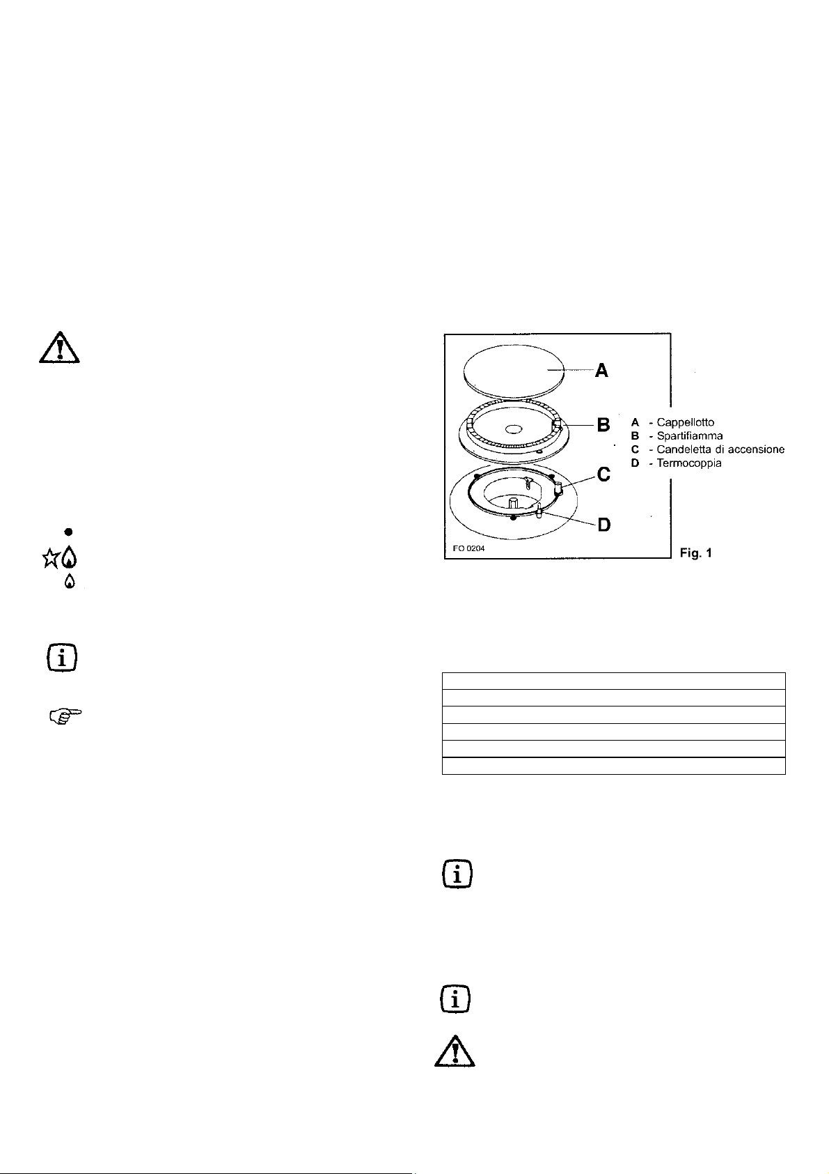
Dopo aver acceso la fiamma, tenete premuta la
manopola per circa 5 secondi; questo tempo è
necessario per riscaldare la "termocoppia"
(Fig.1, lettera D) e disattivare la valvola di
sicurezza, che altrimenti fermerebbe
l'erogazione del gas.
Quindi, controllate che la fiamma sia regolare
e ruotate la manopola fino ad ottenere l'intensità
desiderata.
Se dopo alcuni tentativi la fiamma non si accende,
controllate che il "cappellotto" (indicato nella
figura 1 con la lettera A) e lo "spartifiamma"
(lettera B) siano nella corretta posizione.
Per spegnere la fiamma, ruotate la manopola in
senso orario fino al simbolo .
3
Per un corretto uso dei fornelli
Per un minor consumo di gas ed un migliore rendimento, usate solamente recipienti a fondo piatto e di dimensioni adatte ai fornelli, come evidenziato nella tabella.
Bruciatore diametro diametro
minimo massimo
Ultra-rapido 160 mm. 260 mm.
(tripla corona)
Medio (semirapido) 120 mm. 220 mm.
Piccolo (ausiliario) 80 mm. 160 mm.
Inoltre, non appena un liquido inizia a bollire, fate attenzione a ridurre la fiamma quanto basta per mantenere
l'ebollizione.
L’acciaio inox, se sottoposto ad eccessivo
riscaldamento, puó brunire. Pertanto, si
consiglia la cottura prolungata con pietre
ollari, teglie in terracotta o piastre in ghisa.
È da evitare anche l’impiego di fogli di
alluminio a protezione del piano durante il
funzionamento.
Prima di togliere i recipienti dai fornelli,
abbassate sempre la fiamma o spegnetela.
Durante le cottura in cui vengono impiegati
grassi od olii, sorvegliate attentamente le
Vostre pietanze, perché queste sostanze,
portate ad alte temperature, possono
incendiarsi.
Page 4
Pulizia e manutenzione
Prima di ogni operazione disinserite l’apparecchiatura dalla rete elettrica.
Pulizia generale
Lavate le parti smaltate con acqua tiepida e detersivo,
evitando di usare prodotti abrasivi che potrebbero
rovinarle.
Lavare frequentemente gli spartifiamma e i cappellotti
con acqua bollente e detersivo, avendo cura di togliere
ogni incrostazione.
Risciacquate bene con acqua le parti in acciaio inox,
dopo l’uso, ed asciugatele con un panno morbido.
Per le macchie persistenti usare i normali detersivi non
abrasivi o prodotti specifici, comunemente reperibili in
commercio.
Vi raccomandiamo di non usare per la pulizia pagliette,
lane di acciaio o acidi.
Pulizia dell'accenditore elettrico
L'accensione automatica dei fornelli è assicurata dalla
presenza di una "candeletta" in ceramica ed un elettrodo
in metallo (indicati nella Fig. 1 con la lettera C).
Procedete periodicamente ad una accurata pulizia di
queste parti del piano. Inoltre, per evitare difficoltà di
accensione, controllate che i fori della corona
spartifiamma (lettera B) non siano otturati.
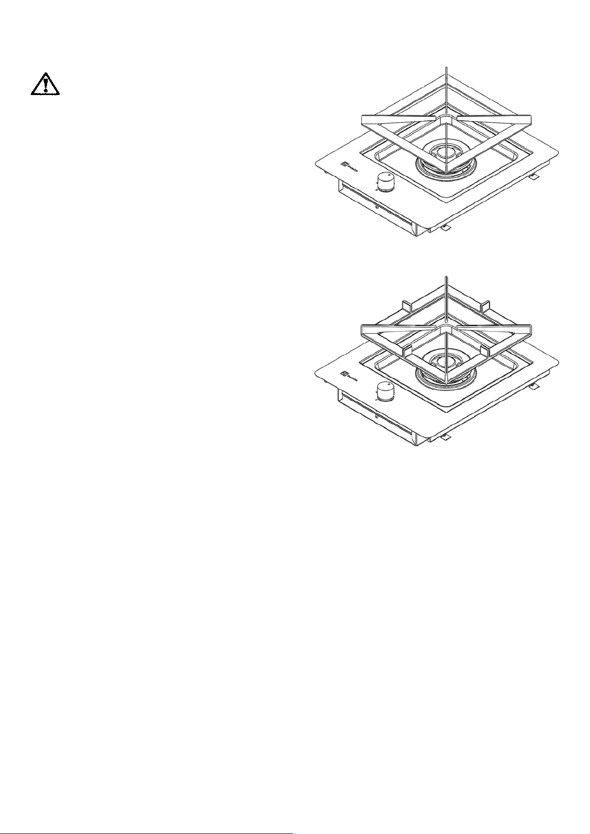
Fig.2
Le griglie del piano di cottura
I piani di cottura possono essere dotati di griglie acciaio
inox (vedi Fig. 2), oppure di griglie in ghisa (più grosse e
pesanti – vedi Fig. 3).
Le griglie possono essere tolte dal piano di cottura per
consentire una migliore pulizia. Sollevate le griglie dal
piano.
Le griglie e i cappellotti cromati
Le griglie e i cappellotti cromati tendono a scurirsi con
l'uso. Questo é un fenomeno del tutto normale ed
inevitabile, ma non compromette assolutamente la
funzionalità del piano.
Sono tuttavia disponibili su richiesta, presso il Vostro
rivenditore od i nostri Centri di Assistenza Tecnica,
griglie e cappellotti smaltati.
4
Fig.3
Manutenzione periodica
Fate controllare periodicamente lo stato di conservazione e di efficacia del tubo del gas, e se presente, del
regolatore di pressione. Qualora venissero riscontrate
anomalie, non richiedete riparazioni, ma fate sostituire la
parte difettosa. A garanzia del buon funzionamento e
della sicurezza, è necessario procedere periodicamente
all’ingrassaggio dei rubinetti di regolazione del gas.
La lubrificazione periodica dei rubinetti deve essere
eseguita SOLAMENTE DA PERSONALE
QUALIFICATO al quale ci si deve rivolgere anche nel
caso si riscontrassero anomalie nel funzionamento
dell’apparecchiatura.
Page 5

Assistenza e ricambi
Questa apparecchiatura, prima di lasciare la fabbrica, è
stata collaudata e messa a punto da personale esperto
e specializzato, in modo da dare i migliori risultati di
funzionamento. Ogni riparazione o messa a punto che si
rendesse in seguito necessaria, deve essere fatta con la
massima cura e attenzione.
Per questo motivo raccomandiamo di rivolgerVi sempre
al Concessionario che ha effettuato la vendita o al
nostro Centro di Assistenza più vicino, specificando il
tipo di inconveniente, il modello dell'apparecchiatura
(Mod.), il numero di prodotto (Prod. No.) ed il numero di
fabbricazione (Ser. No.). Questi dati sono riportati nella
targhetta collocata sull'ultima pagina di questo libretto.
I ricambi originali, certificati dal costruttore del prodotto,
e contraddistinti da questo marchio si trovano solo
presso i nostri Centri di Assistenza Tecnica e Negozi di
Ricambi Autorizzati.
Condizioni di garanzia
La Sua nuova apparecchiatura è coperta da garanzia.
Le condizioni di garanzia sono riportate per esteso
nell'opuscolo "TOP SERVICE" che trovate all'interno
dell'apparecchiatura.
Conservi con cura, insieme all'opuscolo "TOP
SERVICE", la ricevuta o lo scontrino fiscale, oppure
ancora la bolla di accompagnamento, che servono a
documentare l'acquisto della Sua apparecchiatura e la
data in cui é avvenuto.
In caso di intervento del Servizio di Assistenza, esibite
questi documenti al personale incaricato. Senza il
rispetto di questa procedura, il Servizio di Assistenza
sarà costretto ad addebitare qualsiasi eventuale
riparazione.
Il Servizio di Assistenza Tecnica, attraverso i suoi
numerosi Centri autorizzati, presta in Italia assistenza
alle più prestigiose marche di elettrodomestici. In caso di
necessità, potrà cercare il Centro più vicino consultando
l'opuscolo "TOP SERVICE" oppure le Pagine Gialle
nella rubrica Elettrodomestici/ Riparazione, alla voce
“Electrolux Service”.
Caratteristiche tecniche
Potenza bruciatori Gas
Bruciatore ultra-rapido tripla corona (grande) 4,0 kW
Bruciatore ausiliario (piccolo) 1,0 kW
Bruciatore semirapido (medio) 2,0 kW
Categoria
II2H3+
5
Taratura apparecchio Gas Metano 20 mbar
Raccordo di entrata gas G 1/2"
Tensione di alimentazione 230 V 50 Hz
Dimensioni dell'apertura per
l'incasso
Larghezza 447 mm
Profondità 382 mm
Page 6
Istruzioni per l'installatore
ATTENZIONE: Questo apparecchio può essere
installato e funzionare solo in locali
permanentemente ventilati secondo UNI 7129 e UNI
7131.
L’installazione dell’apparecchiatura ed il collegamento
alla rete elettrica devono essere eseguiti solamente da
PERSONALE QUALIFICATO. Prima di qualsiasi
intervento,è necessario verificare che l’apparecchiatura
sia DISINSERITA dalla rete elettrica.
LA SOCIETA’ COSTRUTTRICE DECLINA OGNI
RESPONSABILITÀ’ PER EVENTUALI DANNI DE-
RIVANTI DA UNA INSTALLAZIONE NON
CONFORME ALLE NORME VIGENTI O DA UN
MANCATO RISPETTO DELLE NORME
ANTINFORTUNISTICHE.
Locale di installazione
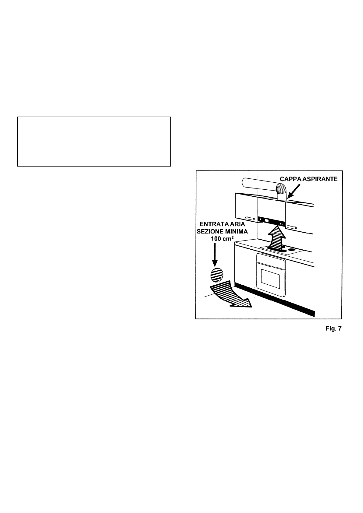
Per il buon funzionamento dell’apparecchio a gas è indispensabile che nel locale possa affluire, in modo naturale, l’aria necessaria alla combustione del gas (l’installatore deve seguire le norme in vigore UNI-CIG 7129
- 7131).
L’afflusso di aria nel locale deve avvenire direttamente
attraverso aperture praticate su pareti esterne (come
indicato nella Fig. 7).
Queste aperture devono avere una sezione libera di
passaggio di almeno 100 cm
Questa apertura deve essere cos truita in modo da non
venire ostruita sia dall’interno che dall’esterno e posizionata vicino al pavimento, preferibilmente al lato opposto all’evacuazione dei prodotti della combustione.
2. .
Nel caso questa apertura non sia fattibile nel locale dove
è installata l’apparecchiatura, l’aria necessaria può
provenire da un locale adiacente, purchè:
questo locale non sia una camera da letto o un ambiente
pericoloso;
questo locale non sia in depressione;
la ventilazione fra il locale dove è installato l'apparecchio
ed il locale adiacente sia assicurata mediante aperture
permanenti (UNI-CIG 7129).
Se si installa il piano di cottura sotto una cappa da
cucina, fare riferimento alle istruzioni per l'installazione
della cappa per la distanza minima tra le
apparecchiature.
6
Page 7
Scarico dei prodotti della combustione
Gli apparecchi di cottura a gas devono scaricare i prodotti della combustione attraverso cappe collegate direttamente a canne fumarie o direttamente all’esterno
(Fig. 7).
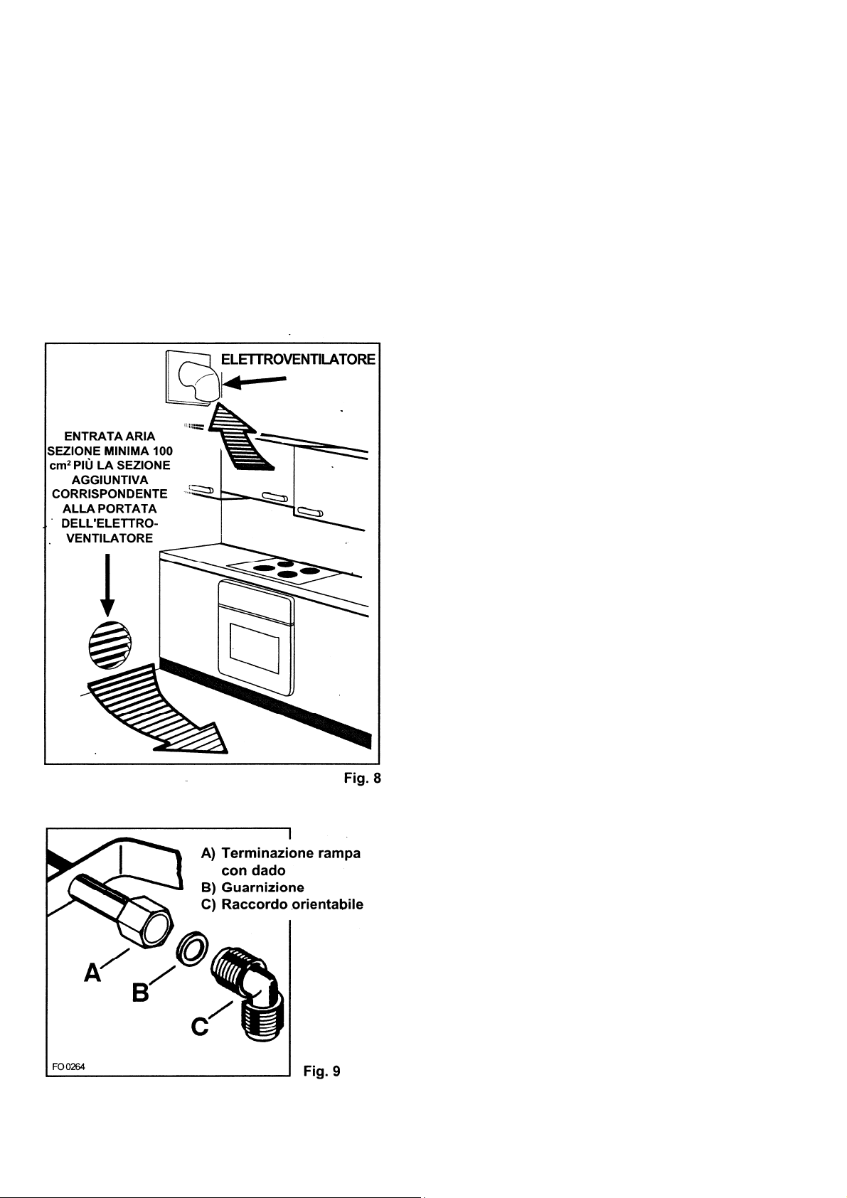
In caso non sia possibile installare la cappa, è necessario l’impiego di un elettroventilatore applicato alla
parete esterna o alla finestra dell’ambiente, purchè esistano le condizioni affinchè l’apertura per la ventilazione
possa essere aumentata (vedi Fig. 8) in proporzione alla
portata dell’elettroventilatore stesso (UNI-CIG7129).
Questo elettroventilatore deve avere una portata tale da
garantire, per un ambiente cucina, un ricambio orario
d’aria pari a 3 - 5 volte il suo volume.
7
Collegamento alimentazione gas
Il collegamento gas deve essere eseguito in conformità
con le norme UNI-CIG 7129 - 7131. L’apparecchiatura
esce dalla fabbrica collaudata e regolata per il tipo di
gas indicato nella targhetta che si trova nella protezione
inferiore, vicino al tubo di collegamento gas.
AccertateVi che il tipo di gas con cui sarà alimentata
l’apparecchiatura sia lo stesso indicato nella targhetta.
In caso contrario procedete secondo le indicazioni
riportate nel paragrafo “Adattamento a diversi tipi di
gas”.
Per il massimo rendimento ed il minor consumo,
assicurateVi che la pressione di alimentazione del gas
rispetti i valori indicati nella tabella delle “Caratteristiche
dei bruciatori”.
Qualora la pressione del gas impiegato sia diversa (o
variabile) rispetto a quella prevista, è necessario installare, sulla tubazione di ingresso, un appropriato
regolatore di pressione per gas canalizzati (NON GPL)
conforme alla norma UNI-CIG 7430.
L’utilizzo di regolatori di pressione per gas liquidi (GPL)
è consentito purchè questi siano conformi alla norma
UNI-CIG 7432.
Sulla zona terminale della rampa, comprensiva di dado
filettato G 1/2", viene montato il raccordo, interponendo
fra i componenti la guarnizione come rappresentato in
Fig. 9. Avvitate le parti senza forzare, orientate il
raccordo nella direzione voluta e quindi serrate il tutto.
Allacciamento
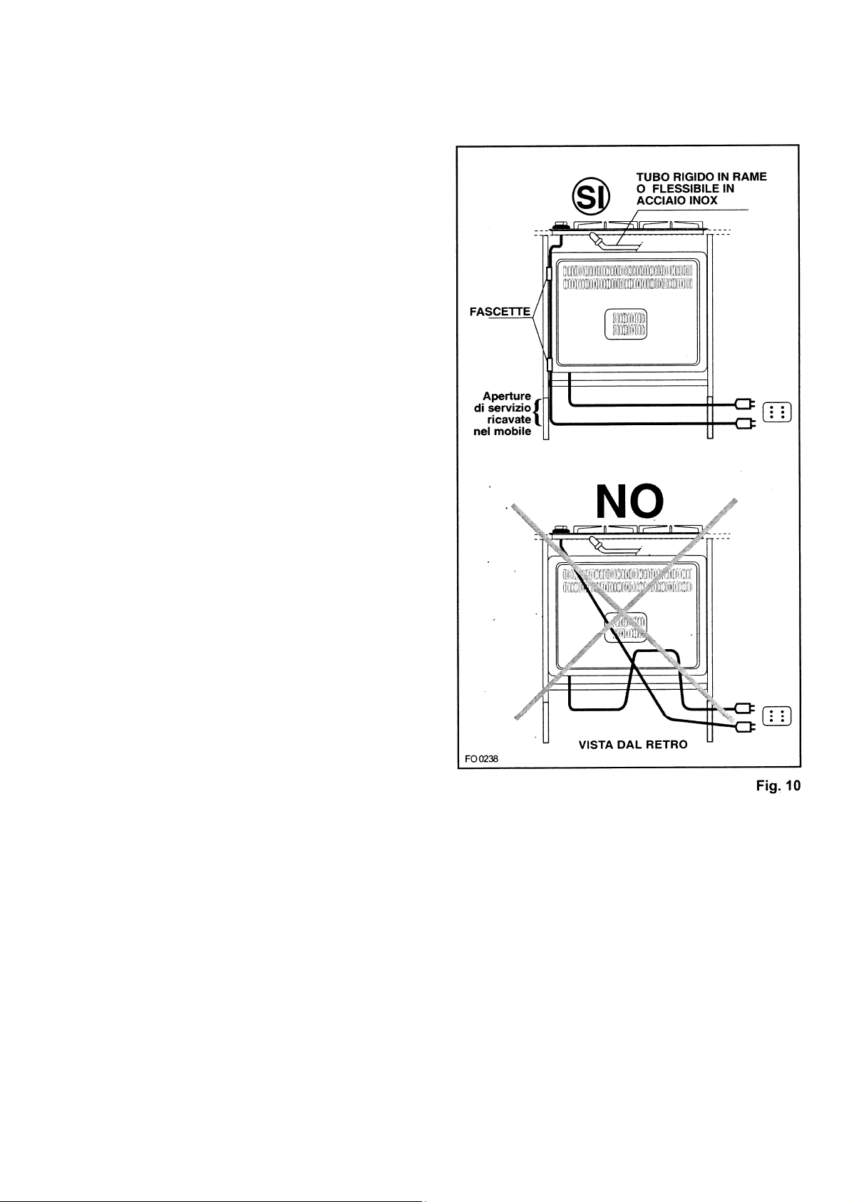
Eseguite l’allacciamento all’impianto gas mediante tubo
metallico rigido e raccordi conformi alla norma UNI-CIG
7129, oppure con tubo flessibile di acciaio inox conforme
alla norma UNI-CIG 9891, limitatamente a quelli la cui
massima estensione è di 2 metri. Fate attenzione che,
nel caso di impiego di tubi metallici flessibili, gli stessi
non vengano a contatto con parti mobili o schiacciati.
Prestate la medesima attenzione anche quando è
previsto un abbinamento forno e piano.
Il raccordo di entrata gas nelle apparecchiature è
filettato 1/2" maschio cilindrico.
Eseguite l’allacciamento evitando sollecitazioni di qualsiasi genere all’apparecchio.
Ad installazione ultimata, verificate sempre la
perfetta tenuta di tutti i raccordi usando una
soluzione saponosa. Non eseguite mai questo
controllo con una fiamma.
Page 8
Collegamento elettrico
L’apparecchiatura è predisposta per un funzionamento
con una tensione di alimentazione di 230 V monofase.
Il collegamento deve essere eseguito in conformità con
le norme e le disposizioni di legge in vigore.
Prima di effettuare il collegamento accertateVi che:
la valvola limitatrice e l’impianto elettrico possano
sopportare il carico dell’apparecchio (vedere targhetta
matricola);
l’impianto di alimentazione sia munito di efficace
collegamento di terra secondo le norme vigenti;
la presa o l’interruttore omnipolare usati siano facilmente raggiungibili con l’ apparecchiatura installata.
Montate sul cavo una spina adatta al carico e collegarla
ad una adeguata presa di sicurezza.
Desiderando un collegamento diretto alla rete, è
necessario interporre fra l’apparecchio e la rete un interruttore omnipolare con apertura minima fra i contatti di 3
mm, dimensionato al carico e rispondente alle norme in
vigore.
Il cavo di terra giallo/verde non deve essere interrotto
dall’interruttore.
Il cavo di fase di colore marrone (proveniente dal
morsetto “L” della morsettiera) deve sempre essere
collegato alla fase della rete di alimentazione.
In ogni caso il cavo di alimentazione deve essere posizionato in modo che in nessun punto raggiunga una
temperatura superiore di 90°C.
Un esempio di percorso ottimale è rappresentato in
Fig.10. Il cavo viene guidato mediante l’utilizzo di fascette fissate lateralmente al mobile, in modo da evitare
qualsiasi contatto con l’apparecchiatura sottostante al
piano di cottura.
8
Page 9
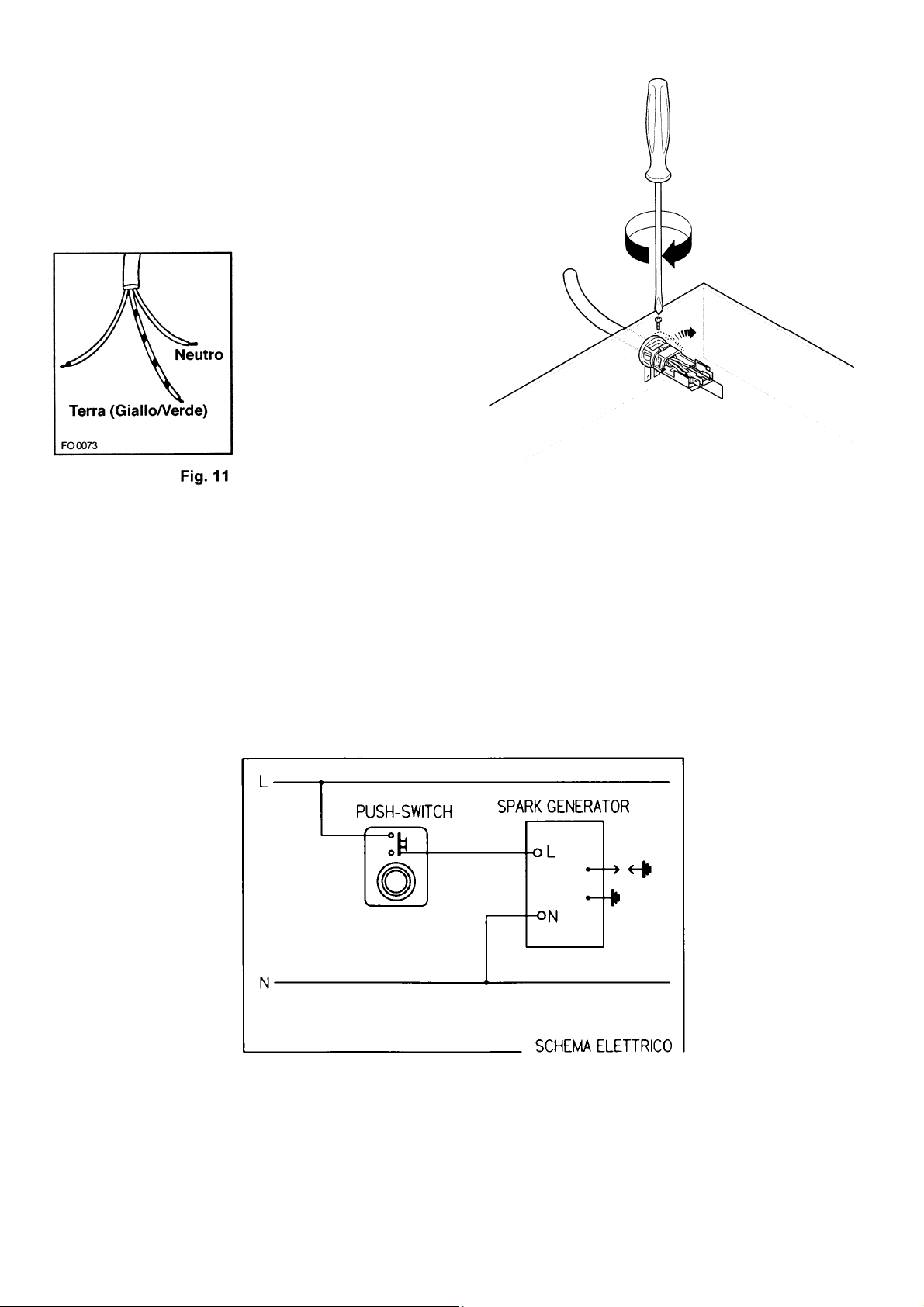
Sostituzione del cavo di alimentazione
Nel caso di sostituzione del cavo è necessario usare
solo cavi del tipo H05V2V2-F T90 adatti al carico e alla
temperatura di esercizio. Inoltre, è necessario che il
cavetto di terra giallo/verde sia più lungo di circa 2 cm.
dei cavetti di fase e neutro (Fig. 11)- (Fig. 12).
Dopo l’allacciamento provare gli elementi riscaldanti
facendoli funzionare per circa 3 minuti.
Schema elettrico piano
Fig.12
9
Page 10

Adattamento ai diversi tipi di gas
Sostituzione degli ugelli
1. Togliete le griglie.
2. Togliete i cappellotti e gli spartifiamma dai bruciatori.
3. Con una chiave a tubo da 7 svitate e togliete (Fig. 13)
gli ugelli, sostituendoli con quelli corrispondenti al tipo di
gas di funzionamento (vedi tabella nella pagina
seguente).
4. Rimontate le parti eseguendo all’inverso le operazioni descritte.
5. Sostituite quindi la targhetta taratura (posizionata
vicino all’attacco della rete gas) con quella corrispondente al nuovo tipo di gas. Quest’ultima si trova nel
sacchetto degli iniettori a corredo.
Qualora la pressione del gas impiegato sia diversa (o
variabile) rispetto a quella prevista, è necessario installare sulla tubazione di ingresso, un appropriato
regolatore di pressione per gas canalizzati (NON GPL)
conformi alla norma UNI-CIG 7430.
L’utilizzo di regolatori di pressione per gas liquidi (GPL)
è consentito purchè questi siano conformi alla norma
UNI-CIG 7432.
Regolazione del minimo
Per regolare il minimo, procedete come segue.
1. Accendete il bruciatore come precedentemente
descritto.
2. Portate il rubinetto sulla posizione di minima fiamma.
3. Estraete le manopole.
4. Agite sullo spillo by-pass indicato nella figura 15.
• Se operate una trasformazione da gas metano a gas
Gpl, avvitate a fondo in senso orario lo spillo bypass.
• In ogni caso il risultato dovrà essere una piccola
fiamma omogenea e regolare su tutta la corona del
bruciatore.
5. Verificate infine che, ruotando rapidamente il
rubinetto dalla posizione di massimo a quella di
minimo, non si abbiano spegnimenti del bruciatore.
Le operazioni di adattamento sopra descritte si possono
effettuare agevolmente, qualunque sia il posizionamento
o il fissaggio del piano di cottura al mobile da cucina.
10
Page 11

DIAMETRI DEL BY-PASS
Ø By-pass
Bruciatore
Ausiliario
Semi-rapido
Ultra-rapido con
tripla corona
del rubinetto
in centesimi
28
32
56
CARATTERISTICHE DEI BRUCIATORI
TIPO DI
GAS
TIPO DI
BRUCIATORE
MARCATURA
UGELLI 1/100
mm
PORTATA
TERMICA
NOMINALE
kW
PORTATA
TERMICA
RIDOTTA kW
GAS
NATURALE
(Metano)
Ultra-rapido
(grande)
Semirapido
(medio)
Ausiliario (piccolo)
146
96
70
4,0
2,0
1,0
1,2
0,45
0,33
GAS
LIQUIDO
(Butano/
Propano)
Ultra-rapido
(grande)
Semirapido
(medio)
Ausiliario (piccolo)
98
71
50
4,0
2,0
1,0
1,2
0,45
0,33
11
PORTATA
NOMINALE IN
m3 /h g/h
0,381
0,190
0,095
-
-
-
-
-
-
288
144
72
PRESSIONE
NOMINALE
mbar
20
28-30/37
Page 12

Tipologie piani cottura
Piani con griglie in ghisa Piani con griglie Inox
Ausiliare
Semirapido
Tripla Corona
12
Page 13

Inserimento e allacciamento
I piani di cottura possono essere montati in un mobile
avente un’apertura per l’incasso dalle dimensioni illustrate
nella figura Fig.17
Il fissaggio del piano al mobile deve essere effettuato
come segue:
Posizionate la guarnizione o l’apposito sigillante (non
forniti in dotazione), sul bordo dei lati frontale,
posteriore e laterali della sfondatura (come mostrato
nella figura 16).
Sistemate il piano nella sfondatura del mobile
curandone la centratura.
Fissate il piano al mobile con le apposite piastrine
(vedi Fig.20).
Nella Fig.18 e Fig.19 è illustrato lo schema di
allacciamento alla linea elettrica e alla rete del gas.
Per l’installazione a semi-filo eseguire, sul top,
solo il foro con dimensione 382x447 senza il
ribassamento da 2 mm.
Fig.18
Fig.19
A) Terminazione rampa con dado
B) Guarnizione
C) Tappo
Fig.16
13
Fig.20
Fig.17
Page 14

Possibilità di inserimento e allacciamento
Tipo1 Tipo2 Tipo3
14
Page 15

Il simbolo
sul prodotto o sulla confezione indica che il prodotto non deve essere considerato come un
normale rifiuto domestico, ma deve essere portato nel punto di raccolta appropriato per il riciclaggio di
apparecchiature elettriche ed elettroniche. Provvedendo a smaltire questo prodotto in modo appropriato, si
contribuisce a evitare potenziali conseguenze negative per l’ambiente e per la salute, che potrebbero derivare da
uno smaltimento inadeguato del prodotto. Per informazioni più dettagliate sul riciclaggio di questo prodotto,
contattare l’ufficio comunale, il servizio locale di smaltimento rifiuti o il negozio in cui è stato acquistato il
prodotto.
15
Page 16

The use of this new appliance is east. Nevertheless it is important to read carefully this handbo ok before installing and using the a ppliance
for the first time. In this way you can obtain the best performance, a void wrong beha ving, using the applianc e in absolute safet y and respect
the environment.
For your safety
Installation
The installation of the appliance and the connection to the
electricity supply has to be carried out by QUALIFIED
PERSONNEL ONLY. Before any intervention it is necessary to
control the appliance is UNCONNECTED from the electricity
supply..
Make sure the air can easily flow around the appliance. A bad
ventilation produces an oxygen defeat.
Make sure the appliance is alimented by the type of gas
indicated on the related adhesive label, in the closeness of th e
connection pipe of the gas supply..
The use of a gas cooker produces heat and humidity in the
room where it is installed
Make sure there is a proper ventilation in the room, by
maintaining opened and efficient the air intakes or by installing
an extraction hood with a discharge conduct.
If you use intensively the appliance or for a prolonged time,
you have to make the ventilation more efficient, for example b y
opening the window or by increasing the power of the electri cal
ventilator if available.
After having unpacked the appliance, make sure the product is
not damaged and that the alimentation cable is in perfect
conditions.
On the contrary. Please contact your retailed before install ing
the appliance.
The manufacturer declines any responsibility in case of not
respecting the accident prevention rules.
First of all consult the content of this handbook.
If you do not find the information you need, please contact the
closest Assistance Centre.
The assistance to this appliance has to be carried out by the
authorized Technical Assistance Centre. Please ask for
original spare parts only.
After having used this appliance please make sure all controls
are in “OFF” position.
If you use an electrical outlet near this equipment, be careful
the cables the appliances you are using do not touch it and are
enough far away from the warm parts of this equipment.
Suggestions for the
environment protection.
All the materials used are compatible with the environm en t an d
recyclable. We be you to give your contribute for the
environment conservation, using the proper waste disposals
channels.
The unused appliances are not waste without value. T hrough
the ecological disposal, different materials used for the
production of Your appliance can be reclaimed.
Please take information on the actual possibilities for the
ecological disposal by your specialized retailer, or through your
local city office.
Before scrapping the appliance, cut the cable the supply cable
in order to make it useless.
Guide to the instructions
Children safety
This appliance has to be used only by adults. Make sure
children do not touch the controls or play with this appliance.
The exposed/external elements of this appliance get hot while
cooking and remain hot for a certain period after bl owing out.
Keep children away from the equipment until when the
equipment get cold.
While using
It is really important to keep this handbook with the equipment
for any future consultation. If you sell or give the equipment to
any other person, make sure you give to the new user this
handbook in order to be informed on the correct working of the
machine and related warnings.
This appliance is designed solely for household use for
cooking food, inside private houses and not for professional
purpose. Avoid to use this appliance for any other purpose. It
may cause hazard to modify or try to modify the features of this
product.
Keep properly cleaned the equipment. Food remaining may
cause fire risks.
In case of faults do not try to repair personally the equipment.
Repairs carried out by non competent personnel may cause
damages or fire risks.
2
reading
These symbols will help you in finding quickly the most
important information.
Safety information
“Step by step” instructions
Useful advices and suggestions
Information related to the environment protection
This appliance is in conformity with the following
Directives CEE:
- 73/23 e 90/683 (related to the Low Voltage);
-89/336 (related to the Electromagnetic
Compatibility);
- 90/396 (related to the Gas working appliances)
- 93/68 (related to the General Directives and
following modifications.
These instructions are only valid for the countries
indicated by the symbols on the cover of the
instruction handbook and the appliance.
Page 17

Index
For the User
For your safety 2
Use instructions 3
Cleaning and maintenance 4
Periodic maintenance 4
Assistance and spare parts 5
Guarantee conditions 5
Use instructions
Before using the appliance, remove all the
packing materials, advertising labels
included and eventual protective film.
The control knobs of the cooker
top
On the front side of the top you will see the knobs for the
gas burners’ running/working. The symbols indicated on
the knobs have the following meaning:
No gas supply (knob turned off)
For the installer
Technical features 5
Installer instructions 6
Connection to the gas supply 7
Connection to the electricity supply 8-9
Adjustment to the different types of gas 10-11
Recess on modular furniture 12-13-14-15
Maximum gas supply
Minimum gas supply
Burners ignition
To obtain the flame easily, turn the burner on
before putting saucepan on the grid.
Push the knob of the corresponding burner
firmly and turn it in an anti- clockwise direction
until the symbol of “maximum gas supply”. The
flame lights up automatically.
Once the burner is on, keep the knob press for
about 5 seconds; This time in necessary to the
thermocouple to warm up. (picture 1, letter D)
and deactivate the safety valve which otherwise
would shut off the gas flow.
At this point , control the flame is regular and
turn the knob up to the requested intensity.
If after some attempts the flame does not light
up, control that the “grid cap” (indicated in
picture 1 with letter A) and the "crown" (letter B)
are on the right position.
To shut of the flame, turn the knob in a
clockwise direction until the symbol.
3
For a correct use of the burners.
For a less gas consume and a better performance, use
only flat-bottomed pots and pans which fit the burners,
see below table.
Burner Pot diameter Pot diameter
minimum maximum
Ultra-rapid (treble crown)160 mm. 260 mm.
Rapid (rapid) 160 mm. 240 mm.
Medium (semi-rapid) 120 mm. 220 mm.
Small (auxiliary) 80 mm. 160 mm.
Also, when a liquid starts boiling, pay attention to lower
the flame as much as suitable to keep it boiling.
The stainless steel, if under excessive heating,
can burnish. Therefore, for the prolonged cooking
ollari stones, earthenware pans or slabs in cast
iron are recommended. Avoid also the
employment of aluminium sheets as protection of
the plan during its working.
Before taking out the pans from the burner,
turn the flame down or shut it off.
During the cooking where greases of oils are
used, look carefully at your cooking as these
substances can cause fire if brought to an high
temperature.
Page 18

Cleaning and maintenance
Before any intervention it is necessary to control
the appliance is UNCONNECTED from the electricity
supply.
General cleaning
Wash the enamelled parts with warm water and detergent,
avoiding to use abrasive products which could scratch it.
Wash often the crowns and the grid caps with boiling
soapy water, pay attention to scrape every scale off.
After the use rinse the stainless steel parts carefully using
water, and dry them with a soft cloth.
For persistent spots use normal non abrasive detergent
easy commonly to be found in commerce. We recommend
you not to use for the cleaning straw hats, steel wools or
acids.
Cleaning of the electrical ignition
The automatic ignition of the burners is assured by the
presence of a ceramic “glow plug” and by a metal longdistance line. (indicated on picture 1 with letter C).
Periodically proceed with an accurate cleaning of these
parts of the hob. In order to avoid any difficulty in the
ignition, control that the holes of the crown (letter B) are
not clogged
Picture 2
Hob’s grids.
Hobs can be equipped by stainless steel grids (see picture
2) or cast iron grids (bigger and heavy – see picture 3).
The grids can be taken off to enable a better cleaning. Lift
the grids up form the hob.
Grids and chromium-plated grids
caps.
Grids and chromium-plated grids caps tend to darken with
their use. This is an absolute regular and unavoidable
phenomenon but it does not absolutely compromise the
hob functionality..
By the way, upon request, there are enamelled grids and
grids caps available by your retailer or our Technical
Assistance Centres.
4
Picture 3
Periodic maintenance.
The condition of the gas-supply pipe should be checked
periodically and, if present, the condition of the pressure
control. If you find any irregularities do not ask to repair
them but ask for their replacement. To grant the proper
working and safety it is necessary to periodically grease
the gas regulation cocks.
The periodic lubrication of the gas cocks must be
done by QUALIFIED PERSONNEL ONY whom has to
be contacted in case of anomalies to the appliance
working.
Page 19

Assistance and spare parts.
This appliance, before leaving the warehouse, has been
tested and set by qualified personnel to obtain the best
working performance. If any repairs are required, they
have to be done with the maximum care and attention.
For this reason we recommend you to contact the
retailer who dealt with the sale or the closest Assistance
Centre, specifying the type of inconvenience, the
appliance model (Mod.), the product number (Prod.
No.) and the manufacturing number (Ser. No.). These
datum are indicated on the label on the last page og the
handbook.
Original spare parts, certified by the product
manufacturer and countersigned by this brand, are
available by our Technical Assistance Centres and
Authorized Spare Parts Shops only.
Guarantee conditions
This new appliance is covered by guarantee. The
guarantee conditions are fully indicated on the leaflet
“TOP SERVICE”, which will be found on the inside of the
appliance.
Hold carefully, with the leaflet “TOP SERVICE” the
receipt or the transport bill, useful to support the
purchase of his appliance and the date of it.
In case of intervention by the Assistance Service, show
these documents to the charged personnel. Without the
respect of this procedure, the Assistance Service will be
obliged to debit you any eventual repairs.
The Technical Assistance Service, throughout its
numerous authorized Centres, gives assistance in Italy
to the most prestigious brands of appliances. If
necessary you can look for the closest Centre by
consulting the “TOP SERVICE” leaflet.
Technical features
Gas burners power
Ultra-rapid treble crown burner (big) 4,0 Kw
Rapid burner (big) 3,0 Kw
Auxiliary burner (small) 1,0 kW
Semi-rapid burner (medium) 2,0 kW
Category
5
II2H3+
Appliance Calibration Methane Gas 20 mbar
Gas inlet connector G 1/2"
Feeling tension 230 V 50 Hz
Dimensions for the recess
opening
Width 447 mm
Depth 382 mm
Page 20

Instructions for the installer
WARNING: This appliance can be installed and can
work only in permanently well-ventilated rooms in
accordance with o UNI 7129 e UNI 7131 regulations.
The installation of the appliance and the connection to
the electric network must be carried out exclusively by
QUALIFIED PERSONNEL ONLY. Before doing any
sort intervention it is important to verify the equipment is
disconnected from the electrical network
THE CONSTRUCTOR COMPANY DECLINES
FROM ANY RESPONSABILITY IN CASE OF
DEMAGES CAUSED BY AN INSTALLATION NOT
IN COMPLIANCE WITH THE CURRENT
REGULATIONS AND WITHOUT RESPECTING
THE ACCIDENT PREVENTION RULES.
Room of installation
In order to have a proper working of the gas appliance it
is of main importance to grant a natural air circulation in
the room, the air necessary for the gas combustion. (the
installer must strictly follow the current directives UNICIG 7129 - 7131).
The air circulation must be ensured through openings in
walls to the outside (as indicated in picture 7).
These openings must have a free passing section of at
least 100 cm
This opening must be made in such a way that cannot
be obstructed from the outside, near the floor level and
positioned on the opposite side of the exhaust system.
2.
If this opening cannot be made in the room where the
appliance is installed, the necessary air can come from a
near room, but:
this room cannot be a bedroom;
this room cannot be in depression;
the ventilation between the room where the appliance is
installed and the near room has to be insured by
permanent openings. (UNI-CIG 7129).
If you install the hob under a hood, please see the
installation instructions of the hood for the minimum
distance between the appliances.
Picture 7
6
Page 21

Discharge of flue gases
Cooking appliances must always discharge the flue
gases into special hoods, which must be connected to
chimneys or have direct access to the outside.(picture7).
If it is not possible to install a hood, it is necessary the
employment of an electric fan fitted to the external wall
or to the window, as long as there are the conditions for
the increase of the ventilation (see picture 8), reported to
the power of the fan itself. (UNI-CIG7129).
This electric fan must have the necessary power to
grant, for a kitchen, an hour air change of 3-5 times its
volume.
Picture 8
Picture 9
7
Connection to the gas-supply.
The cooker should be connected according UNI-CIG
7129 – 7131 directives. The appliance is tested and
adjusted to operate with the type of gas stated on the
rating plate applied in the inferior protection, closed to
the connection gas-supply pipe.
Make sure the type of gas you will use to feed the
appliance is the same indicated on the label.
In the contrary case proceed referring to the paragraph “
Adjustment to the different gas types”.
For the best performance and the lowest consume,
make sure that the gas pressure respect the values
indicated in the table “Features of the burners”.
If the applied gas pressure is different (or variable) from
the scheduled one, it is necessary to install, on the inlet
pipe, a proper gas pressure regulator for gas (NON
GPL) in compliance with UNI-CIG 7430.
The use of pressure regulators for liquid (GPL) is
permitted but it has to be in appliance to the UNI-CIG
7432 Directive.
On the terminal part of the ramp with a thread nut G 1/2”
the pipe fitting has to be mounted, putting between the
parts, the washer as indicated in picture 9. Screw the
parts without forcing, position the washer toward the
requested direction and tighten everything.
Gas connection
The connection of the hob to the gas pipe network must
be made by means of a rigid metallic pipe complying
with the UNI-CIG 7129 directive or using a flexible
connection according the UNI-CIG 9891 directive, which
can be extended to a maximum length of 2 metres. Pay
attention, in case of employment of flexible metal pipes,
they do not get in touch with moving parts or get
crushed. Pay attention even if you combine a hob and
an oven. The gas inlet washer in the appliances is
thread ½” male cylinder. Carry out the gas connection
avoiding any sort of stress to the appliance.
At complete gas connection, always verify the
perfect hold of all the washers by using a soapy
solution. Never carry out this control using a flame
Page 22

Electrical connection
The appliance is set up for a single-phase 230V feeling
voltage. The connection has to be carried out in
compliance with the current directives and law
dispositions.
Before connecting the hob make sure that:
The shaping valve and the electrical system can stand
the appliance load (see the serial number indicated on
the rating plate):
The feed system of the appliance has a proper earth
connection, according the laws in force;
The tap or the single-pole circuit breaker are easy to be
reached from the installed appliance.
Mount on the cable a suitable tap for the load and
connect it to a proper safety tap.
If a straight connection to the electricity is desired, it is
necessary to put a single-pole, with a minimum opening
of 3mm dimensioned to the load and in compliance with
the current directives, between the appliance and the
network.
The brown phase wire (coming out from the L terminal
on the terminal board) must be always connected to the
phase of the feeding network.
In any case the feeding wire has to be positioned so that
it cannot reach, anywhere in its length, a temperature
higher than 90°C.
An example of optimal current path is indicated on
picture 10. The wire is guided by the employment of
clamps fixed on the side of the furniture, in order to
avoid any contact with the appliance under the hob
8
Picture 10
Page 23

Replacing the electrical power
cable
If necessary the electrical power must be replaced
exclusively with power cables type H05V2V2-F T90
suitable for the load and temperature rating.
It is also important that the earth wire (Yellow/Green)
must be at least 2 cm longer than the other phase
neutral (picture 11)- (picture 12).
After the connection test the heating elements letting
them work bout 3 minutes.
Picture 11
Electrical diagram of the top
Picture 12
9
Page 24

Adjustment to different types of gas
Replacing the nozzles
1. Remove the grids.
2. Remove the grid caps and burnes’ crowns.
3. With a 7 socket spanner unscrew and take out the
nozzles (picture 13), substitute them with those
corresponding to the working gas type (see table next
page).
4. Reassemble the parts/elements by executing the
above described operations in the opposite direction.
5. Substitute the calibration rating plate (positioned near
the feed ear). This last one is in the small bag of the
injectors’ kit.
If the pressure of the gas applied is different (or variable)
from the scheduled one, it is necessary to install on the
inlet tube, a proper pressure regulator for gases (NOT
GPL) in compliance with the UNI-CIG 7430.
The employment of pressure regulators for liquid gas
(GPL) is allowed if complying with UNI-CIG 7432.
Adjusting the minimum gas setting of taps.
To adjust the minimum setting proceed as follows:
2. Light up the burners as previously described.
2. Turn the gas cock to the minimum position.
3. Take the knobs out..
4. Work on the by-pass pin indicated on picture 15.
• If you pass from Methane to GPL gas, screw tight
the by-pass pin in the clockwise direction.
• In any case the result must be a small,
homogeneous and regular flame in the entire
burner’s crown. .
5. Verify then that by turning quickly the tap from the
maximum to the minimum position, no burner’s
blowing-out occurs.
The described adjustment’s operations can be easily
done in any positioning of the hob on the kitchen
furniture.
10
Picture 13
Picture 15
Page 25

BY-PASS DIAMETRES
Ø By-pass
Burner
Auxiliary
Semi-rapid
Rapid
Ultra-rapid with
treble crown
tap
in hundredth
28
32
40
56
BURNERS SPECIFICATIONS
TYPE OF
GAS
TYPE OF
BURNER
NOZZLES
MARKING
1/100 mm
NOMINAL
THERMIC
RATE kW
REDUCED
TERMIC
RATE kW
NATURAL
GAS
(Methane)
Ultra-rapid (big)
Rapid
Semi-rapid
(medium)
Auxiliary (small)
146
119
96
70
4,0
3,0
2,0
1,0
1,2
0,65
0,45
0,33
1,2
0,65
0,45
0,33
LIQUID
GAS
(Butane/
Propane)
Ultra-rapid (big)
Rapid
Semi-rapid
(medium)
Auxiliary (small)
98
86
71
50
4,0
3,0
2,0
1,0
11
NOMINAL IN RATE
m3 /h g/h
0,381
0,305
0,190
0,095
-
-
-
-
-
-
-
-
288
202
144
72
NOMINAL
PRESSURE
mbar
20
28-30/37
Page 26

Typesofcookertops
TopswithstainlessgridsTopswithironsteelgrids
Auxiliary
Semi‐rapid
Triplecrown
12
Page 27

Positioning and connection
Cookers can be mounted on a furniture with a recess
opening with dimensions shown in picture 17
The fixing of the hob to the top has to be done as follows:
Position the suitable dope or gasket (not issued), on
the front, back and side edges of the worktop’s
opening (as shown in picture 16).
Ad just the hob on the opening of the furniture paying
attention to centre it.
Fix the hob to the furniture using provided brackets
(see picture 20).
In picture 18 and picture 19 are illustrated the outline
of the connection to the electric supply and the gas
supply.
For thick edge installation, execute on the top, only
the hole with dimension 382x447millimetres without
the ribassamento from 2 millimetres stubbling.
Picture 18
Picture 19
A) Ending of the ramp and nut
B) Gasket
C) Tap
Fig.16
13
Fig.20
Picture 17
Page 28

Possibilities of positioning and connection
Type1 Type2 Type3
14
Page 29

The symbol
on the product, or on the documents accompanying the product, indicates that this
appliance may not be treated as household waste. Instead it shall be handed over to the applicable collection
point for the recycling of electrical and electronic equipment.
Disposal must be carried out in accordance with local environmental regulations for waste disposal.
For more detailed information about treatments, recovery and recycling of this product, please contact your
local city office, your household waste disposal service or the shop where you purchased the product.
15
 Loading...