

Electrolux FPRH17D7KF All Refrigerator Professional Series, FPUH17D7KF All Freezer Professional Series Servicing
Page 1
All about
Servicing
All Refrigerator and
All Freezer Professional
17 Cu. Ft. Units
With Mechanical Controls
™
Electrolux Major Appliances; North America
250 Bobby Jones Expwy
Augusta, GA 30907
Publication #5995556338 Revision A December 2009
Page 2

Page 3

Section 1 Basic Information
This Manual has been prepared to provide Electrolux Service Personnel with Operation and Service Information for the
following models.
FPRH17D7KF All Refrigerator Professional Series
FPUH17D7KF All Freezer Professional Series
Safe Servicing Practices
Avoid personal injury and/or property damage by observing important Safe Servicing Practices.
Following are some limited examples of safe practices:
1. DO NOT attempt a product repair if you have any doubts as to your ability to complete the repair in a safe and
satisfactory manner.
2. Always Use The Correct Replacement Parts as indicated in the parts documentation. Substitutions may defeat
compliance with Safety Standards Set For Home Appliances.
3. Before servicing or moving an appliance:
• Remove power cord from the electrical outlet, trip circuit breaker to OFF position, or remove fuse.
• Turn off water supply if unit has an icemaker.
4. Never interfere with the proper operation of any safety device.
5. Use ONLY REPLACEMENT PARTS CATALOGED FOR THIS APPLIANCE. Substitutions may defeat
compliance with Safety Standards Set For Home Appliances.
6. GROUNDING: The standard color coding for safety ground wires is GREEN, or GREEN with YELLOW
STRIPES. Ground leads are not to be used as current carrying conductors.
It is EXTREMELY important that the service technician reestablish all safety grounds prior to completion of
service. Failure to do so will create a hazard.
7. Prior to returning the product to service, ensure that:
• All electrical connections are correct and secure.
• All electrical leads are properly dressed and secured away from sharp edges, high temperature components,
and moving parts.
• All non-insulated electrical terminals, connectors, heaters, etc. are adequately spaced away from all metal
parts and panels.
• All safety grounds (both internal and external) are correctly and securely connected.
• All panels are properly and securely reassembled
• Water supplies are turned ON if shut off prior to service.
ATTENTION!!!
This service manual is intended for use by persons having electrical and mechanical training and a
level of knowledge of these subjects generally considered acceptable in the appliance repair trade.
Electrolux Home Products, Inc. cannot be responsible, nor assume any liability, for injury or damage
of any kind arising from the use of this manual.
© 2009 Electrolux Home Products, Inc.
1-1
Page 4

Section 1 Basic Information
Section 1 - Basic Information ......................... 1-1
Safe Servicing Practices ....................................... 1-1
Table of Contents ................................................ 1-2
Child Safety ........................................................ 1-3
Model and Serial Number Breakdown ................... 1-4
Serial Plate ......................................................... 1-4
Model FPUH17D7K Unit Features.......................... 1-5
Model FPRH17D7KF Unit Features ....................... 1-6
Section 2 - Installation Information .............. 2-1
Important Safety Instructions .............................. 2-1
Location ............................................................. 2-3
Electrical Information .......................................... 2-4
Leveling .............................................................. 2-4
Electrical Information .......................................... 2-4
Cut-Out Dimensions ............................................ 2-5
Water Supply ...................................................... 2-6
Connecting the Water Valve to the Ice Maker ....... 2-7
Trim And Riser Kit Installation Instructions ........... 2-8
Setting Up The Trim And Grill Assembly ............... 2-9
Installing Trim & Grill Assembly Into Cabinetry ..... 2-10
Installing The Riser Kit ........................................ 2-11
Leveling The Refrigerator And Freezer .................. 2-14
How To Adjust Levelers ....................................... 2-14
Final Positioning .................................................. 2-14
Care & Cleaning Of Your Trim Kit ......................... 2-15
Door Removal ..................................................... 2-15
Door Handle Mounting Instructions ...................... 2-15
Section 3 - Mechanical Control ....................... 3-1
Temperature Control ........................................... 3-1
Defrost Timing .................................................... 3-1
Section 4 - Refrigeration System .................. 4-1
Definitions ......................................................... 4-1
Safety Warnings ................................................. 4-1
Compressor Testing ........................................... 4-1
Charging Sealed Systems .................................... 4-1
Soldering ........................................................... 4-2
Basic Components .............................................. 4-2
Refrigerant Cycle................................................ 4-2
Low/High Side Leak or Undercharge .................... 4-3
Testing for Refrigerant Leaks .............................. 4-3
Compressor Oil Contamination ............................ 4-3
To Flush the System........................................... 4-4
To Use Dry Nitrogen to Flush the System ............ 4-4
To Use Refrigerant to Flush the System ............... 4-4
Installing a New Compressor .............................. 4-5
Condenser Replacement ..................................... 4-6
Filter-Drier Installation ........................................ 4-7
Evaporator and Suction Line Replacement ........... 4-7
Equipment Needed for Evacuation & Recharging .. 4-8
Installing Evacuation and Recharging Equipment .. 4-8
Evacuating System ............................................. 4-9
Charging the System .......................................... 4-9
Preparing the Charging Cylinder .......................... 4-9
Final Leak Test .................................................. 4-10
Verify Refrigerant Type in the System ................. 4-11
Dedicated Equipment ......................................... 4-11
R-134a Refrigeration Systems ............................. 4-11
Miscibility of R-134a and Ester Oil ....................... 4-11
Water in the Refrigeration System ....................... 4-12
Vacuum Pump Maintenance ................................ 4-13
Refrigerant Leaks ............................................... 4-13
Leak Detection ................................................... 4-14
R-134a Properties .............................................. 4-14
HFC-134a, CFC-12 Pressure Temp. Chart ............. 4-15
Inhalation Toxicity .............................................. 4-16
Cardiac Sensitization .......................................... 4-16
Spills or Leaks .................................................... 4-16
Skin and Eye Contact ......................................... 4-16
Combustibility of HFC-134a ................................. 4-17
Leak Testing ...................................................... 4-17
Bulk Delivery and Storage ................................... 4-17
Filling and Charging Operations........................... 4-17
Refrigerant Recovery Systems ............................. 4-17
Thermal Decomposition ...................................... 4-17
1-2
Page 5
Section 1 Basic Information
Section 5- Component Teardown .................... 5-1
Warnings and Cautions ......................................... 5-1
Exterior Components ............................................ 5-2
Door Handle .................................................... 5-2
Kickplate ......................................................... 5-2
Door Hinge and Door Assembly ........................ 5-2
Door Stop Assembly ......................................... 5-3
Door Gasket and Inner Panel ........................... 5-3
Door Storage Components .................................... 5-4
Adjustable Door Bins ........................................ 5-4
Dairy Door ...................................................... 5-4
Gallon Door Bin ............................................... 5-4
Door Switch .................................................... 5-4
Interior Components ............................................ 5-5
Adjustable Interior Shelves ............................... 5-5
Crisper Drawer ................................................ 5-5
Crisper Cover Assembly .................................... 5-5
Light Shield ..................................................... 5-6
Light Fixture .................................................... 5-6
Baffle Plate...................................................... 5-6
Evaporator Cover ............................................. 5-6
Thermostat Control .......................................... 5-7
Evaporator Fan Assembly ................................. 5-7
Defrost Thermostat .......................................... 5-8
Defrost Heater ................................................. 5-8
Evaporator ...................................................... 5-9
Compressor Area Components
All Refrigerator and All Freezer-Pro Models
Power Cord ..................................................... 5-10
Water Valve .................................................... 5-10
Defrost Timer .................................................. 5-11
Filter-Drier ...................................................... 5-11
Compressor ..................................................... 5-12
Drain Pan ........................................................ 5-13
Condenser Fan Motor ....................................... 5-13
Condenser ....................................................... 5-14
Section 6 - Parts List ........................................ 6-1
FOR YOUR SAFETY
Do not store or use gasoline, or other fl ammable vapors
and liquids in the vicinity of this or any other appliance.
Read product labels for fl ammability and other warnings.
CHILD SAFETY
• Destroy carton, plastic bags, and any exterior
wrapping material immediately after the freezer is
unpacked. Children should never use these items to
play. Cartons covered with rugs, bedspreads,
plastic sheets or stretch wrap may become airtight
chambers, and can quickly cause suffocation.
• Remove all staples from the carton. Staples can
cause severe cuts, and destroy finishes if they come
in contact with other appliances or furniture.
• An empty, discarded ice box, refrigerator, or freezer
is a very dangerous attraction to children.
• Remove and discard any spacers used to secure the
shelves during shipping. Small objects are a choke
hazard to children.
• Remove the door(s) of any appliance that is not in
use, even if it is being discarded.
RISK OF CHILD ENTRAPMENT
Child entrapment and suffocation are not problems of the
past. Junked or abandoned refrigerators or freezers are
still dangerous – even if they will sit for “just a few days”.
If you are getting rid of your old refrigerator or freezer,
please follow the instructions below to help prevent accidents:
• Remove the door/lid.
• Leave shelves in place so children may not easily
climb inside.
All Refrig. Door Exploded View & Parts List ........... 6-1
All Refrig. Cabinet Exploded View & Parts List ........ 6-2
All Refrig. System Exploded View & Parts List ....... 6-4
All Freezer Door Exploded View & Parts List ......... 6-6
All Freezer Cabinet Exploded View & Parts List ..... 6-8
All Freezer System Exploded View & Parts List ...... 6-10
Section 7 - Troubleshooting ............................ 7-1
Troubleshooting Chart ......................................... 7-1
Section 8 - Wire Diagrams ............................... 8-1
All Refrigerator Wiring Diagram ............................ 8-1
All Freezer Wiring Diagram ................................... 8-2
• Have the refrigerant removed by a qualified
technician.
1-3
Page 6
Section 1 Basic Information
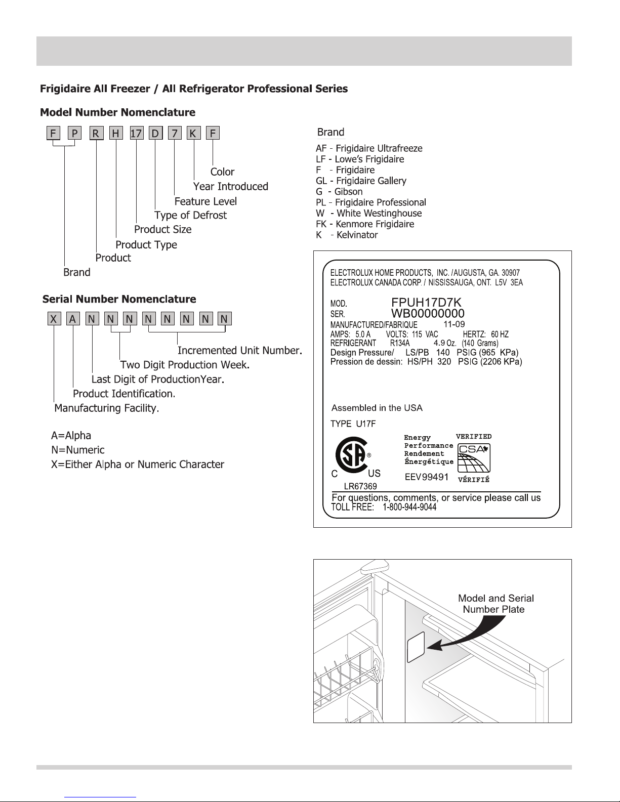
Serial Plate
The serial plate is located inside the cabinet on the left
sidewall. The technician should always refer to the
serial plate to assure refrigerant type and quantity, as
well as electrical ratings and operating pressures.
1-4
Page 7
Section 1 Basic Information
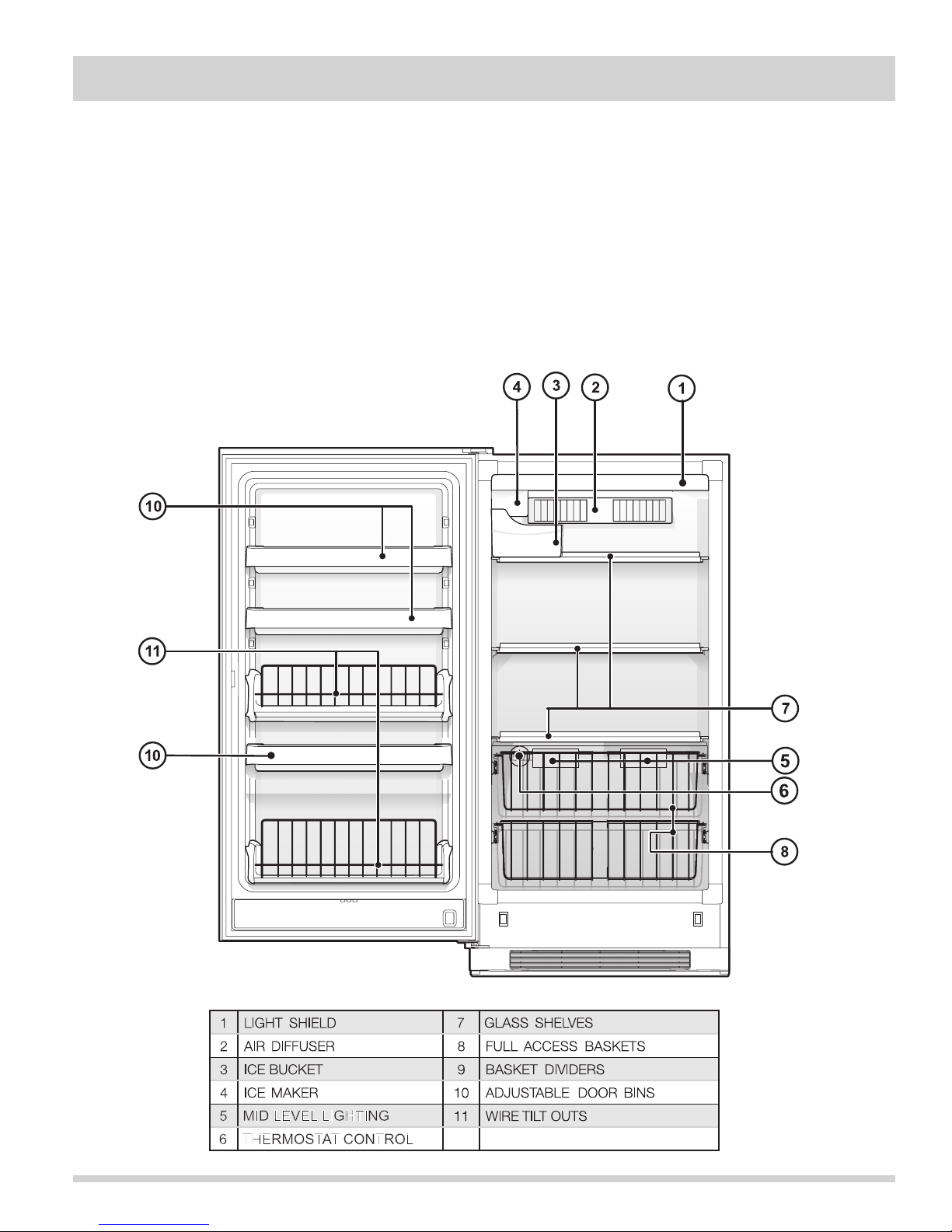
All Freezer Professional Series with Mechanical Control
Performance
Temperature Control
7ºF cut-in, -5ºF cut-out @ number 1 setting.
Room Ambient ....................................................... 70°F 90°F
Freezer Compartment Temperature ......................... 5 to 12°F 5 to 12°F
Percent Running Time ............................................ 30 - 40% 45 - 55%
*Wattage Range (Last 1/3 of cycle) ........................ 110 - 125 115 - 130
Suction Pressure (Cut-in, cut-out), PSIG .................. 14 - 0 14 - 0
High Side Pressure (Last 1/3 of cycle), PSIG ............ 100 - 125 150 - 165
Model FPUH17D7K Unit Features
1-5
Page 8
Section 1 Basic Information
All Refrigerator Professional Series with Mechanical Control
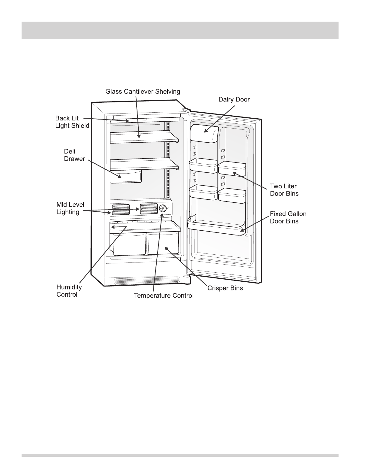
Model FPRH17D7KF Unit Features
1-6
Page 9
Section 2 Installation Information
Recognize safety symbols, words and labels:
Safety items throughout this manual are labeled with a WARNING or CAUTION based on the risk type as described
below:
WARNING
This symbol alerts you to situations that may cause serious body harm, death or
property damage.
CAUTION
This symbol alerts you to situations that may cause bodily injury or property damage.
WARNING
To reduce the risk of fire, electrical shock, or injury when using a freezer and/or refrigerator, follow
basic safety precautions including the following:
- Read all instructions before operating the freezer and/or refrigerator.
- Before performing any type of service or installation, make sure that electric power to the freezer
and/or refrigerator is disconnected.
- To avoid the possibility of explosion or fire, do not store or use combustible, flammable, or
explosive liquids or vapors (such as gasoline) inside or in the vicinity of this or any other appliance.
- This appliance is equipped with a three-prong grounding plug for protection against possible
electric shock hazards. Plug it only into a dedicated, grounded electrical outlet. When only a
standard two-prong electrical outlet is available, the customer must have it replaced with a
dedicated, properly grounded three-prong electrical outlet before using this Appliance.
Do not under any circumstances, cut or remove the third (ground) prong from the power cord.
Do not use an adapter plug.
Do not use an extension cord.
Do not use a power cord that is frayed or damaged.
The use of a ground fault interrupter (GFI) is not recommended.
- Do not install or use a damaged appliance. If you receive a damaged appliance, immediately
contact your dealer or builder.
- The installer must show the customer the location of the power plug so that they know where and
how to disconnect power to the freezer and/or refrigerator.
- Do not install, repair, or replace any part of the freezer and/or refrigerator unless specifically
recommended in the literature accompanying it. A qualified service technician should perform all
other service.
WARNING
Electrolux Home Products Inc. cannot be held responsible for damage to property or injury to persons caused by
failure to comply with the installation, maintenance and safety instructions contained in this Service Manual.
2-1
Page 10
Section 2 Installation Information
Doors
Handles are secure and tight.
Door seals completely to cabinet on all sides.
Freezer and/or refrigerator door is level across top.
Leveling
Freezer and/or refrigerator is level, side-to-side
and tilted 1/4” (6mm) front-to-back.
Toe grille is properly attached to freezer and/or
Cabinet is setting solid on all corners.
Electrical Power
House power turned on.
Freezer and/or refrigerator plugged in.
Final Checks
Shipping material removed.
Freezer and/or refrigerator temperatures set.
Registration card sent in.
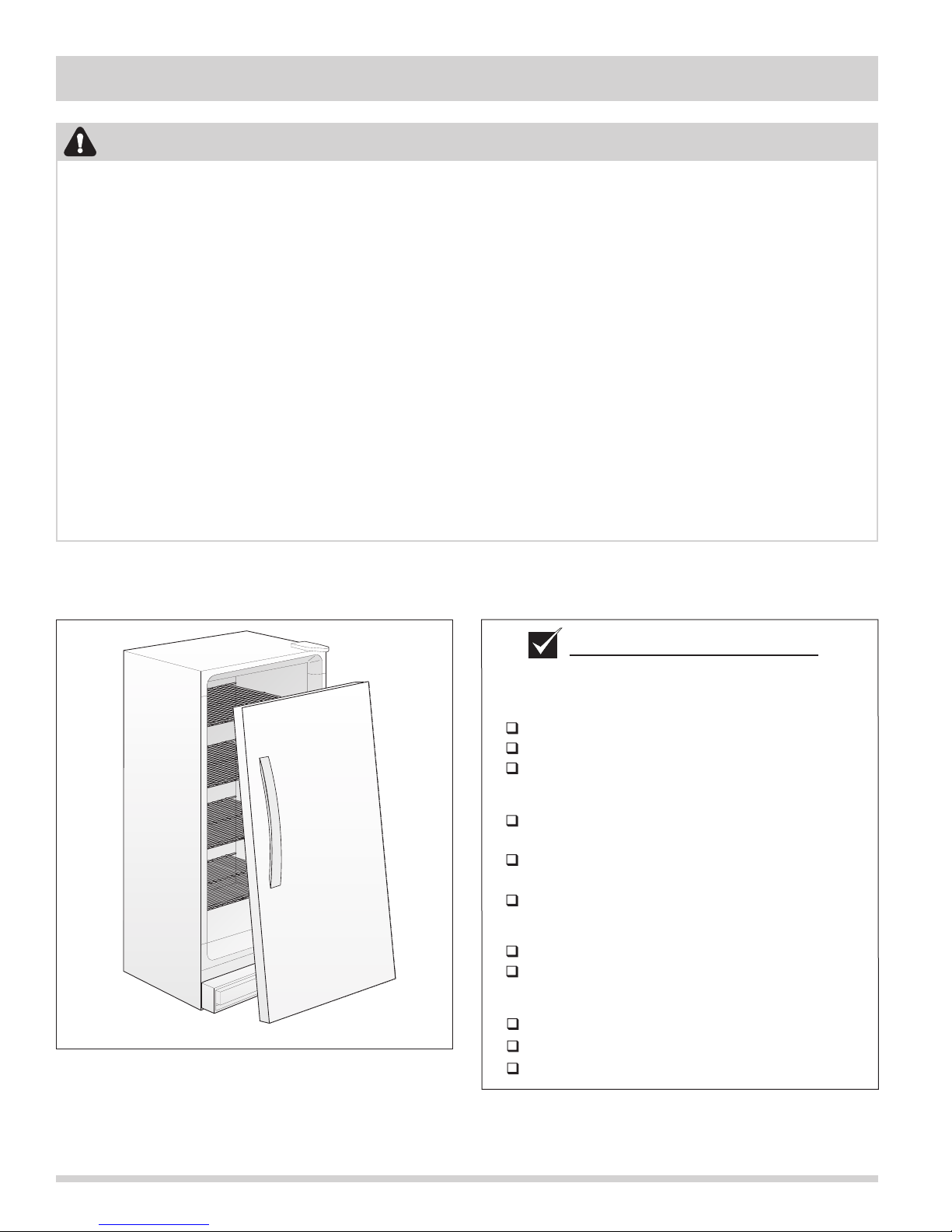
Installation Checklist
refrigerator.
WARNING
Destroy carton, plastic bags, and any exterior wrapping material immediately after the refrigerator/
freezer is unpacked. Children should never use these items for play. Cartons covered with rugs,
bedspreads, plastic sheets or stretch wrap may become air tight chambers and can quickly cause
suffocation.
A child might suffocate if he crawls into the freezer to hide or play. Remove the door/lid of the
refrigerator/freezer when not in use, even if you plan to discard the freezer. Many communities have
laws requiring you to take this safety precaution.
Remove or discard any spacers used to secure the shelves during shipping. Small objects are a choke
hazard to children.
Child entrapment and suffocation are not problems of the past. Junked or abandoned refrigerators or
freezers are still dangerous– even if they will sit for “just a few days”. If you are getting rid of your
old refrigerator or freezer, please follow the instructions below to help prevent accidents:
•Remove the door/lid.
•Leave shelves in place so children may not easily climb inside.
•Have the refrigerant removed by a qualified technician.
2-2
Page 11
Section 2 Installation Information
Location
1. Choose a place that is near a grounded electrical
outlet. Do Not use an extension cord or an adapter
plug.
2. If possible, place the freezer and/or refrigerator
out of direct sunlight and away from the range,
dishwasher or other heat sources.
3. The freezer and/or refrigerator must be installed on
a floor that is level and strong enough to support a
fully loaded freezer.
4. Consider water supply availability for models
equipped with an automatic ice maker.
5. The freezer and/or refrigerator should be located
where surrounding temperature will not exceed
110ºF (43ºC) or drop below 40°F (5°C).
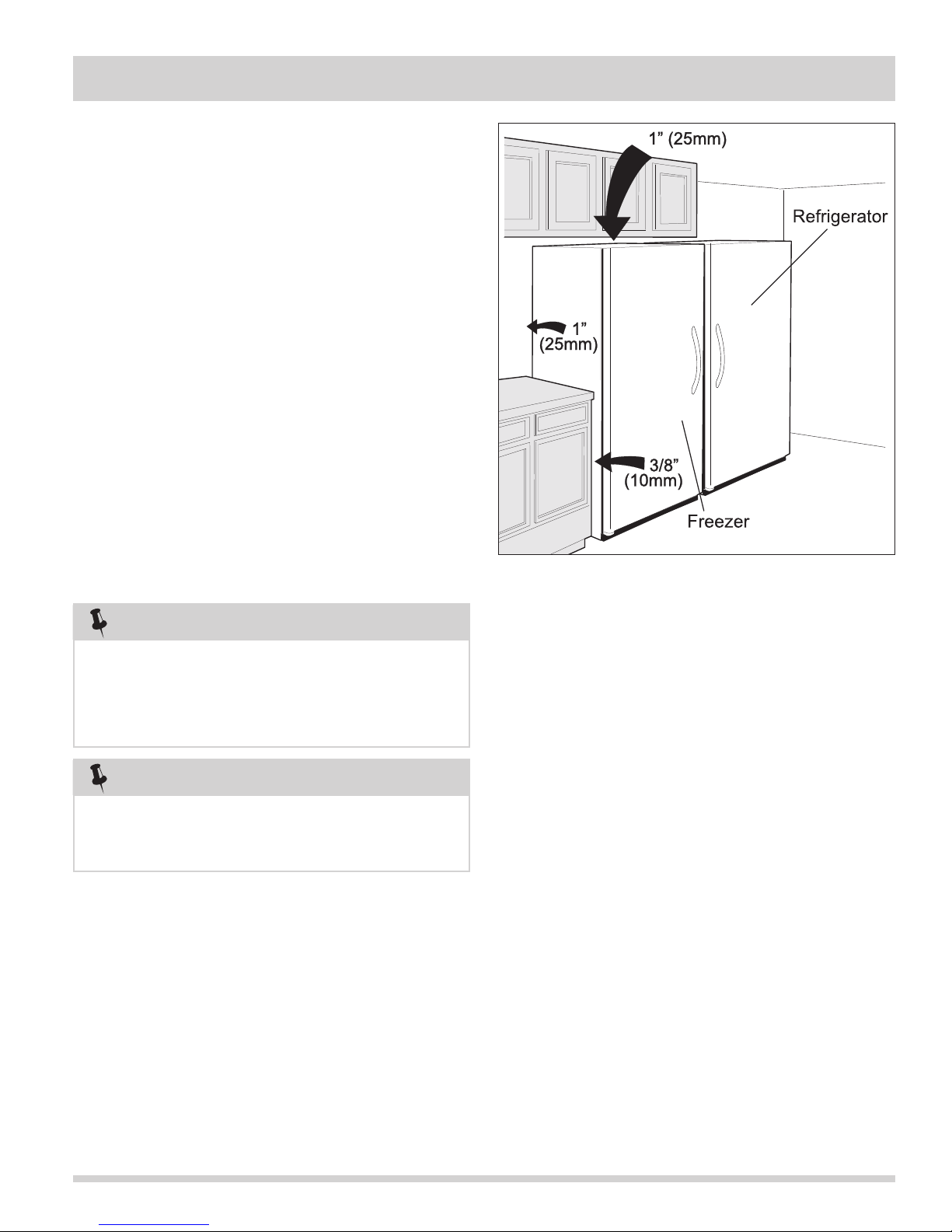
6. For ease of installation, proper air circulation and
electrical connections, see Figure 2-1 for
recommended clearances.
7. For dynamic condenser models, DO NOT block
the toe grille on the lower front of your freezer.
Sufficient air circulation is essential for the proper
operation of your freezer and/or refrigerator.
Figure 2-1. Installation Clearances
NOTE
The exterior walls of the refrigerator/freezer may
become quite warm as the compressor works to
transfer heat from the inside. Temperatures as much
as 30°F warmer than room temperatures can be
expected.
NOTE
If your refrigerator and/or freezer is placed with the
door hinge side against a wall, you may have to allow
additional space so the door can be opened wider.
2-3
Page 12
Section 2 Installation Information
Electrical Information
These guidelines must be followed to ensure that safety
mechanisms in the design of this freezer will operate
properly.
Refer to the serial plate for correct electrical rating. The
power cord of the unit is equipped with at three-prong
grounding plug for protection against shock hazards. It
must be plugged directly in to its own properly grounded
three-prong receptacle, protected with a 15 amp time
delay fuse or circuit breaker. The receptacle must be
installed in accordance with the current edition of the
National Electrical Code (NFPA 70) the local codes and
ordinances. Consult a qualified electrician. Receptacles
with Ground Fault Circuit Interrupters (GFCI) are NOT
RECOMMENDED. DO NOT USE AN EXTENSION CORD
OR AN ADAPTER PLUG.
If the voltage varies by 10% or more, freezer and/or
refrigerator performance may be affected. Operating the
freezer with insufficient power can damage the motor.
Such damage is not covered under the warranty. If you
suspect your voltage is high or low, consult your power
company for testing.
To prevent the freezer from being turned off accidentally,
do not plug the unit in to an outlet controlled by a wall
switch or pull cord.
Do not pinch, knot, or bend the power cord in any
manner.
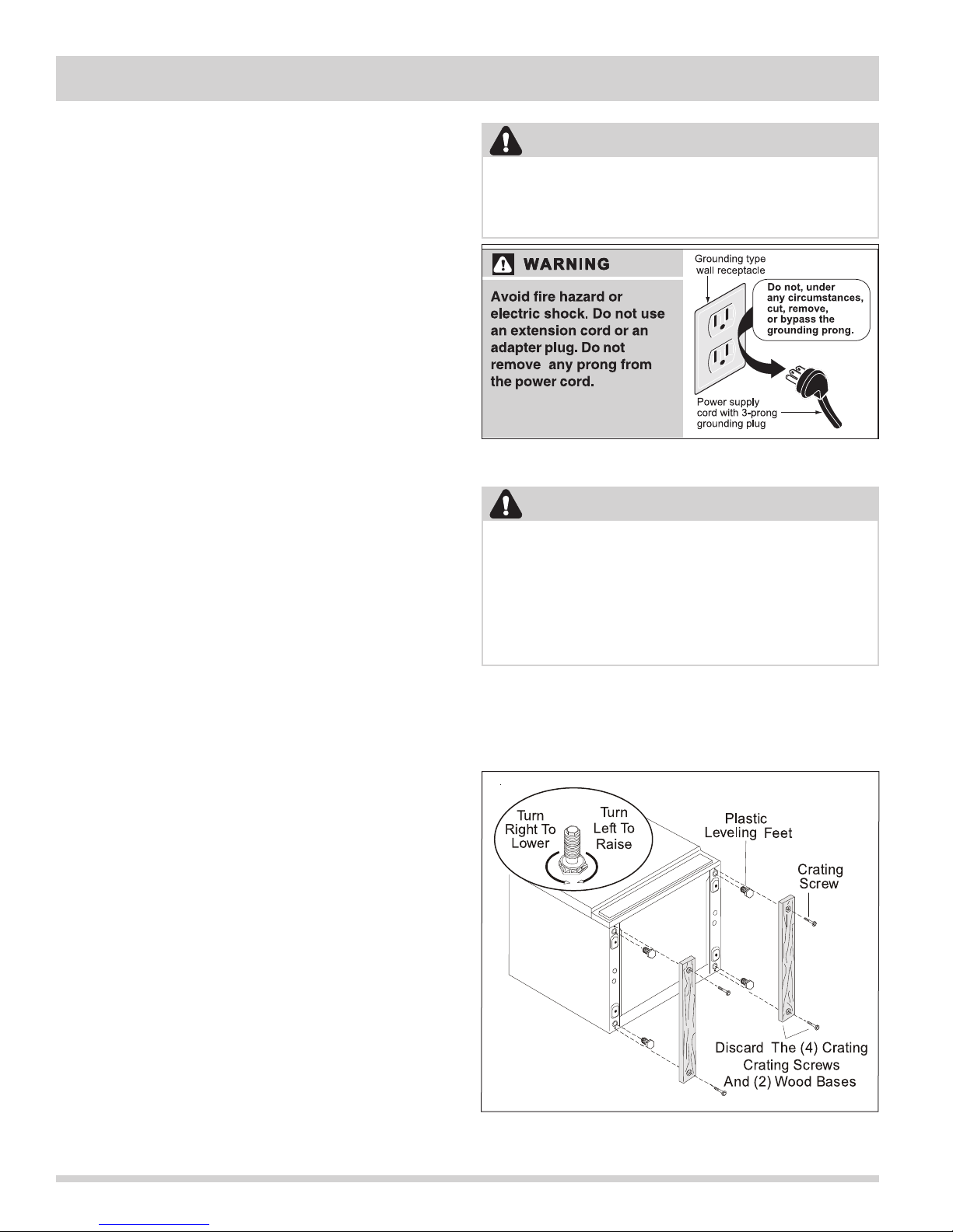
WARNING
Avoid fire hazard or electric shock. Do not use
an extension cord or an adapter plug. Do not
remove any prong from the power cord.
Figure 2-2. Electrical Receptacle
WARNING
Never unplug the freezer by pulling on the
power cord. Always grip the plug firmly and pull
straight out from the receptacle.
Turning the control to “OFF” turns off the compressor but does not disconnect power to other
electrical components.
Leveling
The freezer and/or refrigerator must have all bottom
corners resting firmly on a solid floor. The floor must be
strong enough to support a fully loaded freezer and/or
refrigerator.
It is VERY IMPORTANT for your freezer and/or
refrigerator to be level in order to function properly. If
the unit is not leveled during installation, the door/lid
may be misaligned and not close or seal properly,
causing cooling, frost or moisture problems.
After discarding crating screws and wood base, use a
carpenter’s level to level the unit from front to back.
Adjust the plastic leveling feet in front, ½ bubble higher,
so that the door closes easily when left half way open.
2-4
Figure 2-3. Leveling Unit
Page 13
Section 2 Installation Information
Cut-Out Dimensions
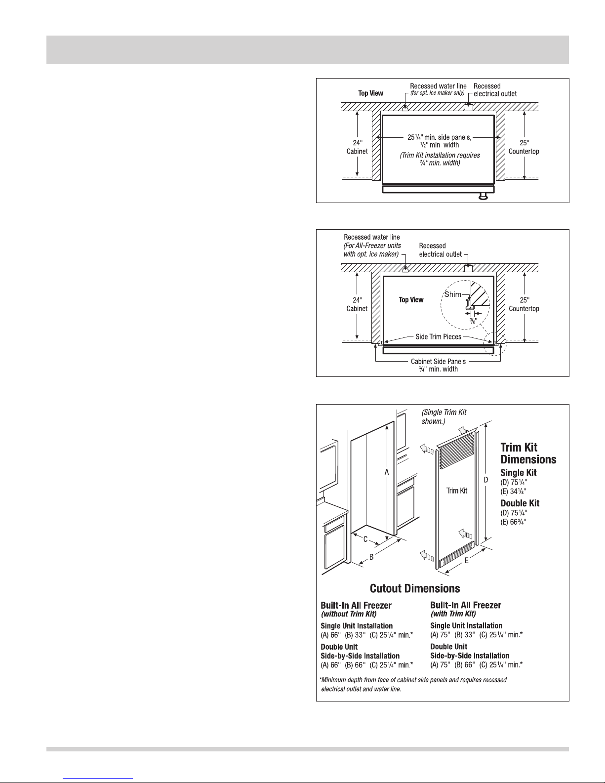
1. Minimum opening of 66” High x 33” Wide x 25-1/4”
Deep opening required for single-unit “Built-In Look”
installation. 66” Wide required for double-unit
installation. (66” High to be measured from finished
floor to underside of soffit or overhead cabinet.)
2. Minimum 25-1/4” depth requires recessed electrical
outlet and copper water line.
3. Remove all wall / floor molding prior to built-in
installation.
4. When installing a unit adjacent to wall, cabinet or
other appliance that extends beyond front edge
of unit, 20” minimum clearance is recommended
to allow for optimum 140° door swing, providing
complete crisper access and removal. (Absolute 4”
minimum clearance will ONLY allow for 90° door
swing which will provide limited crisper access with
restricted removal.)
5. Water line for ice maker can enter opening through
floor or rear wall. Copper tubing recommended
between cold water line and water connection
location. Water line tubing recommended is 48”
minimum length by 1/4” diameter. Installation of
easily accessible shutoff valve in water line required.
6. To allow for ease of moving out side-by-side units
after installation, 84” minimum length of coiled
copper tubing recommended.
7. If optional Single or Double Trim Kit is to be used,
different cutout dimensions are required.
Figure 2-4. Freezer Unit Cut-out
Figure 2-5. Refrigerator Unit Cut-out
Optional Accessories
• Single Trim Kit – (PN# ALLFRZKIT).
• Double Trim Kit – (PN# DUOTRIMKIT).
• Ice Maker Kit – (PN# IM501).
Figure 2-6. Trim Kits
2-5
Page 14
Section 2 Installation Information
Water Supply
The ice maker (if equipped) requires a permanent
water supply to function correctly. During installation,
establish this water supply by connecting a copper tube
from the household water system to a valve at the rear
of the unit.
WARNING
To avoid property damage:
• Use copper tubing for the water supply line
(plastic tubing is more likely to leak).
Manufacturer is not responsible for any
damage if plastic tubing is used for supply
line.
• Ensure water supply and installation comply
with state and local laws and regulations.
• DO NOT install water supply tubing where
temperatures fall below freezing.
• Chemicals from a malfunctioning softener can
damage the ice maker. If the ice maker
is connected to soft water, ensure that the
softener is maintained and working properly.
Requirements:
• Access to a cold water line with pressure of 20-120
psi. (System supplied with cold water only.)
• Copper tubing with ¼ inch (6.4mm) Outside
Diameter (OD). Length is the distance from the rear
of the unit to your household water supply line, plus
seven (7) feet (2.1 meters).
• A shut-off valve for the connection between your
household water line and the refrigerator supply line.
DO NOT use a self-piercing shut-off valve.
• A compression nut and ferrule (sleeve) for the water
supply connection at the water valve inlet.
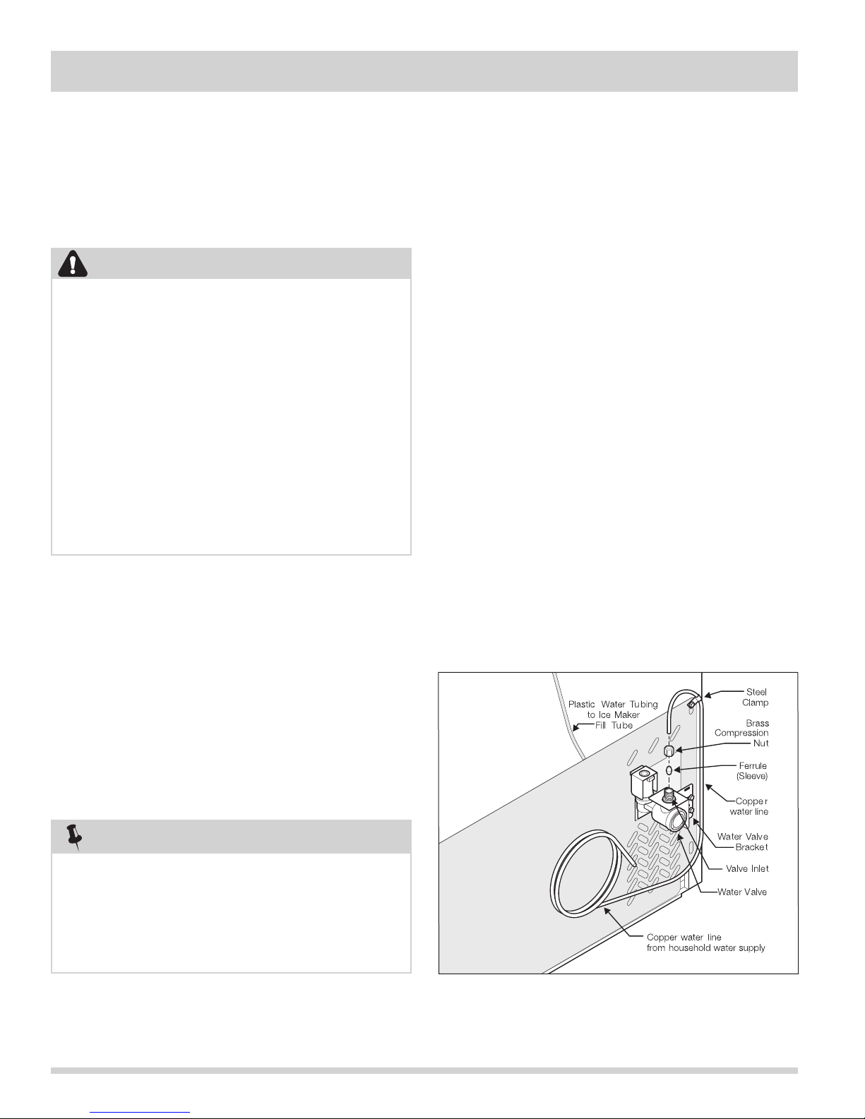
To connect the water supply to the rear of the
unit (See Figure 2-7a):
1. Ensure that the unit is unplugged.
2. Flush the supply line until water is clear by placing
the end of the copper tube in a sink or bucket and
opening the shut-off valve. Close shut-off valve
when flushing is complete.
3. Remove and discard the plastic cap from the water
valve inlet at the rear of the unit.
4. Slide the brass compression nut, then the ferrule
(sleeve) onto the copper tube.
5. Push the copper tube into the water valve inlet as
far as it will go (¼ inch or 6.4mm).
6. Slide the ferrule (sleeve) into the water valve and
finger-tighten the compression nut onto the valve.
Tighten another half turn with a wrench but DO NOT
over-tighten.
7. Secure the copper tube to your units’ rear panel with
a steel clamp and screw.
8. Coil the excess copper tubing (about 2½ turns)
behind your refrigerator as shown. Arrange coiled
tubing to avoid vibration or wear against other
surfaces.
9. Open water supply shut-off valve and tighten any
connections that leak.
10. Connect unit to home power supply.
11. To turn ice maker On, lower wire signal arm. (See
ice maker front cover for On/Off position of arm.
NOTE
Water line kit number 5303917950, available from
the appliance dealer at additional cost, contains 25
feet (7.6 meters) of 1/4” OD copper tubing, a saddle
type shut-off valve (non piercing), (2) 1/4” brass
compression nuts, (2) ferrules/sleeves, and instructions
for installing a water supply line.
2-6
Figure 2-7a. Water Connection
Page 15
Section 2 Installation Information
Connecting the Water Valve to the Ice Maker
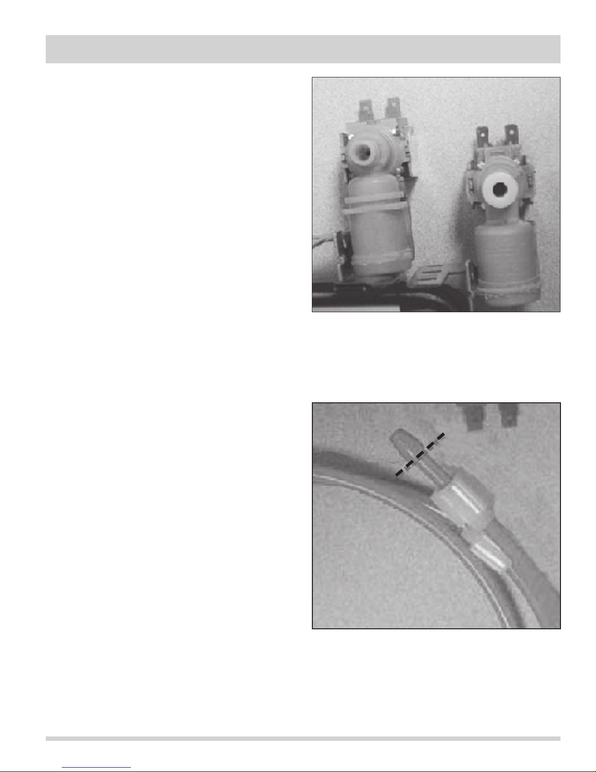
For models Serial Number WB92254219 and greater built
after June 1, 2009, the units will have a different water
valve than earlier production models. The new water
valves have a quick connect outlet fitting which takes a
standard .255 diameter plastic tube. The old style of
water valves required a flanged tube and a threaded nut
to make the water connection. (See Figure 2-7b)
Water Line Kit PN 297114101 will still be used to make
the water line connections between the new style water
valve and ice maker, however the flanged tube will have
to be modified as described in the steps below:
1. Using a box cutters or knife, cut the pointed end
from the water line just below the raised point. Be
sure to cut straight across the water line. Do not
leave open/cut end at an angle. (See Figure 2-7c)
2. Remove the cut end and plastic nut from the water
line and discard.
3. Measure 11/16” from the end of the water line and
place a mark on the line with a permenent marker.
4. Insert the modified water line into the push-type
fitting on the new valve, making sure that the water
line is pushed in up to the mark.
5. Inspect for leaks once water supply is turned on.
The water valve on the left is the old style
threaded outlet connection. The water valve on
the right has the push-type outlet fitting.
Figure 2-7b. Water Valves
Figure 2-7. Water Connection
Figure 2-7c. Cut along dotted line to modify
tubing.
2-7
Page 16
Section 2 Installation Information
Trim And Riser Kit Installation
Instructions
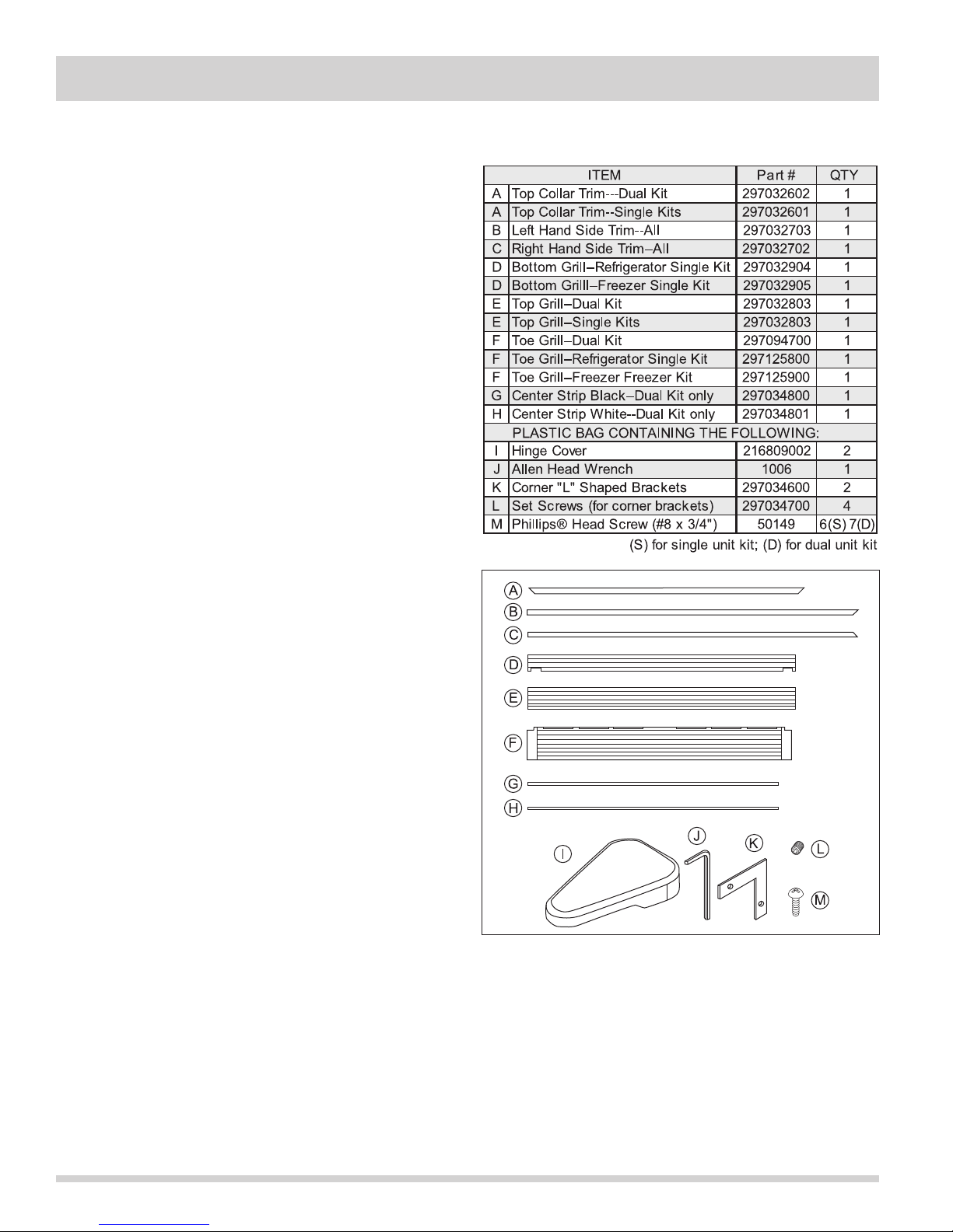
The Dual Trim and Riser Kit consists of the following:
• Riser Kit - 2 packages
• Hardware Kit - 1 bag
• Trim Kit - 1 package
• Installation Instructions
The Single Trim and Riser Kit consists of the following:
• Riser Kit - 2 packages
• Hardware Kit - 1 bag
• Trim Kit - 1 package
• Installation Instructions
Before starting installation, have the following tools on
hand:
• PhillipsTM Screwdriver
• Shims - Wooden or Plastic
• Tape Measure (min. 7” length)
• Safety Glasses
• Tape (Duct or Masking)
• Carpenter’s Level
• Drill & 1/8” Bit
• 1/2” Socket Wrench
The following items should be with the collar kit option:
Before You Begin
• Be careful when unpacking components. Do not use
sharp objects when removing packaging material.
This may scratch the surface of trim components.
• Make sure that your rough opening is:
Double-wide kit: 66” wide by 79” tall (from top of
flooring) by at least 25-1/4” deep from the cabinet’s
front face. Outside dimensions of the installed kit
are 66-3/4” wide by 79-1/4” high.
Single-wide kit: 33” wide by 79” tall (from top of
flooring) by at least 25-1/4” deep from the cabinet’s
front face. Outside dimensions of the installed kit
are 33-3/4” wide by 79-1/4” high.
• Make sure there is a large, clear area of floor
(approx. 10’ by 8’) to assemble the trim kit. Place a
drop cloth over the floor to prevent scratching of the
trim kit and/or floor.
• Use extreme care when handling the metal trim
pieces. Corners are very sharp and easily damaged
if dropped.
Figure 2-8. Trim Kit Components
2-8
Page 17
Section 2 Installation Information
Setting Up The Trim And Grill Assembly
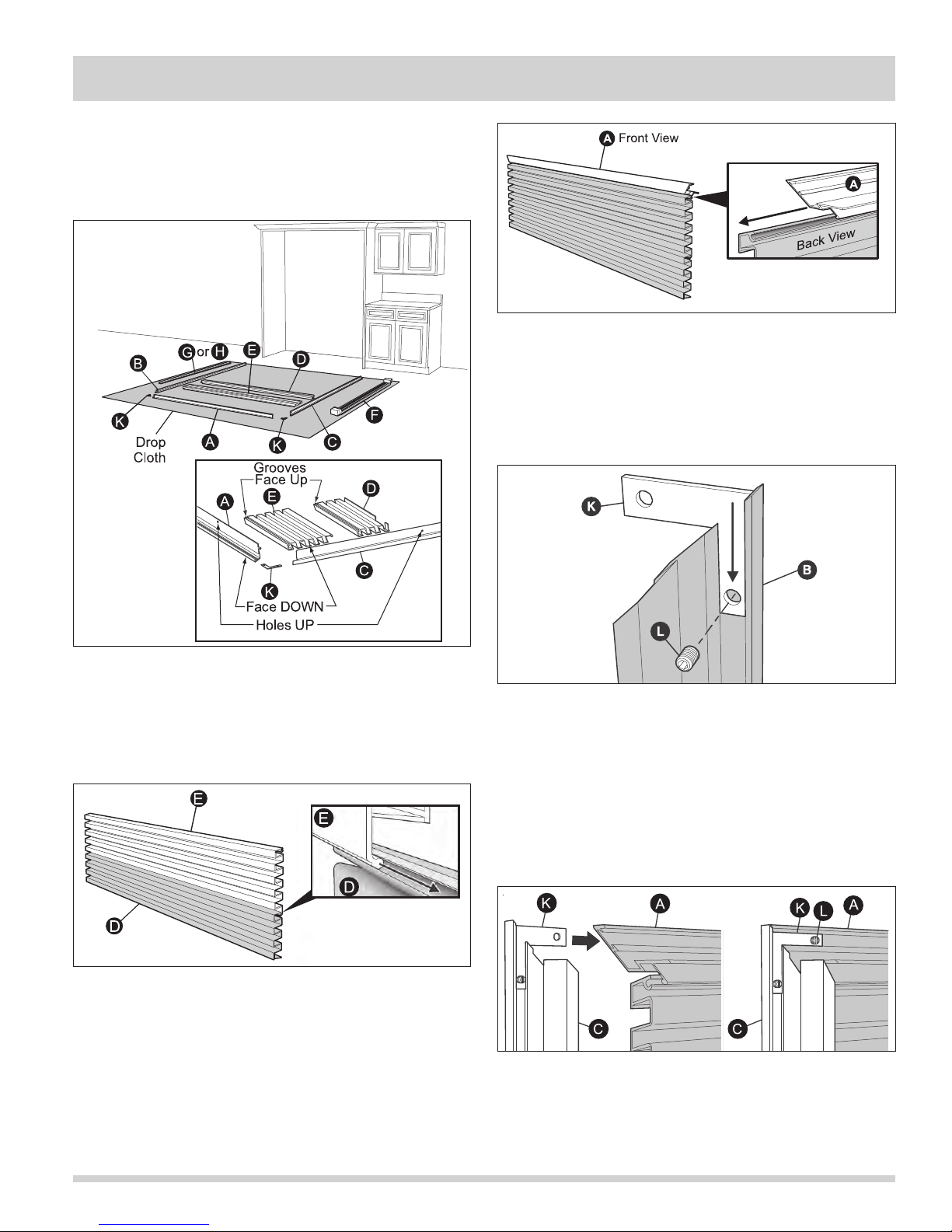
1. Lay the parts out on a cleared area face down. Be
sure to place a drop cloth over the floor to prevent
scratching the trim kit and/or floor. (See Figure 2-9).
Figure 2-11.
4. Attach brackets (K) to the angled end of each side
trim (B and C). Gently secure brackets to side trim
by tightening set screws (L) only until snug to avoid
dimpling the extrusion face. DO NOT overtighten.
(See Figure 2-12).
Figure 2-9.
2. Slide top grill (E) and bottom grill (D) together.
Make sure the ends are flush then tape together to
prevent parts from sliding. (See Figure 2-10).
Figure 2-10.
3. Slide grill assembly into top collar trim (A). Tape
together to prevent from sliding. (See Figure 2-11).
Figure 2-12.
5. Join each side trim (B and C) to the top trim (A).
Make sure the ends of the Grill Assembly are
captured in the channel of each side trim, then tape
in place. Gently secure brackets (K) to top trim (A)
by tightening set screws (L), only until snug to avoid
dimpling the trim face. DO NOT overtighten. (See
Figure 2-13).
.
Figure 2-13.
2-9
Page 18
Section 2 Installation Information
Installing Trim & Grill Assembly Into Cabinetry
1. First, place protective covering where side trim will
contact the floor near rough opening. Then, stand
up the grill and frame assembly and center in rough
opening. You may need to use several pieces of
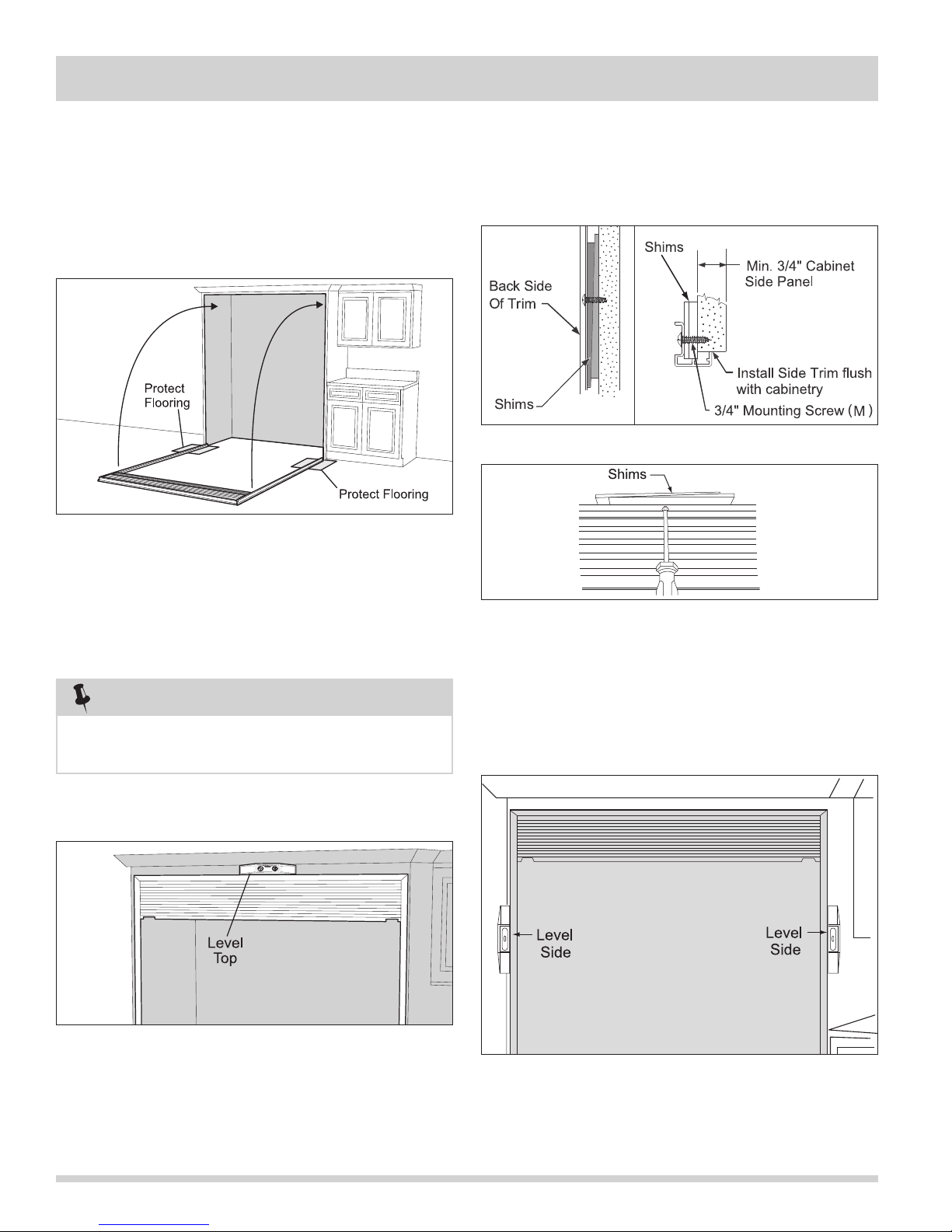
tape at the top corners and top center to temporarily
hold the assembly in place. (See Figure 2-14).
Figure 2-14.
4. Shim as necessary (shims are not included). (See
Figures 2-16 and 2-17). Next, secure both ends of
top trim (A) to cabinetry using two 3/4” mounting
screw (M) through the holes at each end. Make sure
all screws are snug across the top.
Figure 2-16.
2. Making sure the frame is flush up against the front
surface of cabinetry, carefully run one mounting
screw (M) through the center hole of the top trim
(A) and into the cabinetry. DO NOT tighten at this
time.
NOTE
Some cabinet substrates may require pre-drilling holes
using a 1/8” diameter drill bit.
3. Level the top of the trim frame using a carpenter’s
level. (See Figure 2-15).
Figure 2-17.
5. Using a carpenter’s level, check that each side
is vertical. Shim as necessary (shims are not
included). Next, secure top and bottom of each side
trim to cabinetry using two 3/4” mounting screws
(M). (See Figure 2-18).
Figure 2-15.
2-10
Figure 2-18.
Page 19
Section 2 Installation Information
Installing The Riser Kit On Early Models
(See Figure 2-19 to identify)
1. First, place a protective covering on the floor to
prevent damaging either the refrigerator unit, freezer
unit or the floor.
2. Lay the unit on its side, making sure the side with
the handle is laying closest to the floor to prevent
door from falling open.
3. Remove the two plastic leg levelers on the bottom
front side of the units.
4. Remove riser from its box. Locate plastic bag
containing the mounting hardware needed to install
the riser kit to the unit. The bag should contain four
mounting bolts and four washers for each riser.
5. Position the riser on the bottom of the unit, making
sure the slanted end is toward the back of the unit.
6. Place a washer on the bolt and feed the bolt
through the hole in the top of the riser kit and into
the threaded hole in the foot of the unit. DO NOT
TIGHTEN AT THIS TIME.
7. Repeat the above procedure for the three remaining
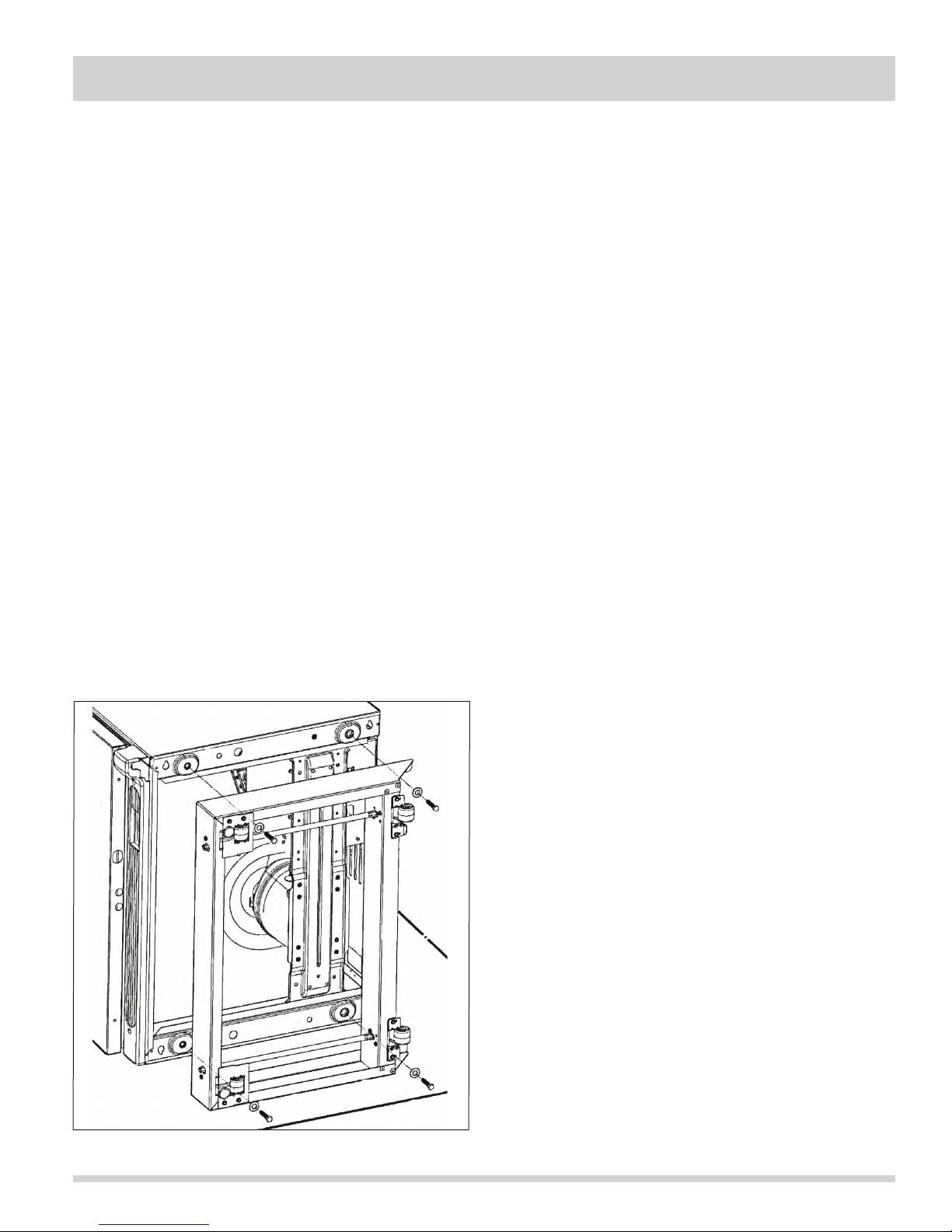
attachment points. (See Figure 2-19).
8. Once all four bolts are secured to the four feet of the
unit, tighten the bolts using a 1/2” socket or open
end wrench.
9. After installation, carefully upright the unit with the
help of an assistant.
Installing The Riser Kit On Late Models
(See Figure 2-20 to identify)
1. First, place a protective covering on the floor to
prevent damaging either the refrigerator unit, freezer
unit or the floor.
2. Lay the unit on its side, making sure the side with
the handle is laying closest to the floor to prevent
door from falling open.
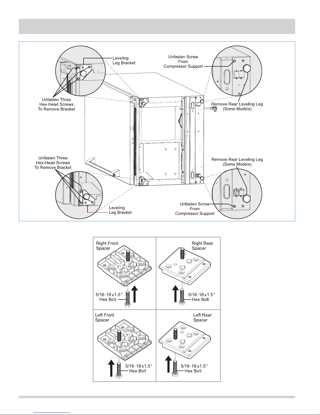
3. Remove the two front leg leveler brackets, (2)
compressor support screws and rear leg levelers, if
applicable, as shown in Figure 2-20.
4. Remove plastic spacers and Hex Bolt 5/16-18UNC x
1.5” from the box and assemble the two together as
shown in Figure 2-21.
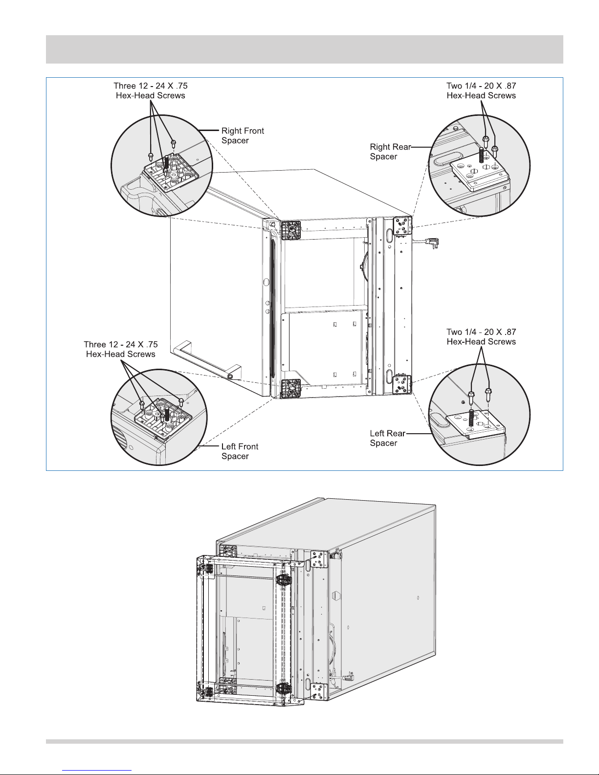
5. Using three HWD #12-24 X .70 screws, fasten the
right front Riser Kit Spacer & Hex Bolt Assembly as
shown in Figure 2-22.
6. Using three HWD #12-24 X .70 screws, fasten the
left front Riser Kit Spacer & Hex Bolt Assembly as
shown in Figure 2-22.
7. Using two HWD ¼ -20 x .87 screws, fasten the right
rear Riser Kit Spacer & Hex Bolt Assembly as shown
in Figure 2-22.
8. Using two HWD ¼ -20 x .87 screws, fasten the left
rear Riser Kit Spacer & Hex Bolt Assembly as shown
in Figure 2-22.
9. Now that all the spacers are assembled on the unit,
you may position the riser on the bottom of the unit,
making sure the slanted end is toward the back of
the unit. See Figure 2-23.
10. Once in position, feed the riser through the four
bolts. Properly mounted riser should hang in place.
11. Place a washer on the bolt and thread into the
provided Nut (6/16” UNC). DO NOT TIGHTEN AT
THIS TIME.
12. Once all four nuts are secured to the four bolts,
tighten using a socket or an open wrench.
13. After installation, carefully upright the unit with the
help of an assistant.
Figure 2-19.
2-11
Page 20
Section 2 Installation Information
Figure 2-20.
2-12
Figure 2-21.
Page 21
Section 2 Installation Information
Figure 2-22.
Figure 2-23.
2-13
Page 22
Section 2 Installation Information
Leveling The Refrigerator And Freezer
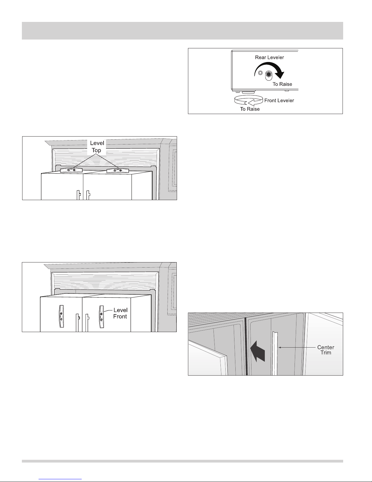
1. Remove the plastic top hinge covers and replace
with the supplied silver hinge covers (I).
2. Remove the plastic toe grill panels at the bottom of
each unit. Save the four screws as they will be used
later in the installation.
3. Place a carpenter’s level across the top of the door.
Using a tape measure, adjust all four levelers so that
each door is level and to a height of 69-3/8” across
top front edge of door. (See Figures 2-24 and 2-25).
Figure 2-24.
4. Place a carpenter’s level vertically on the front of
the door and level so that the front surface of door
is vertical. Recheck to make sure top front edge
of door is still at a height of 69-3/8”. Adjust as
necessary. (See Figures 2-24 and 2-25).
Figure 2-26.
Final Positioning
1. Connect the ice maker water lines (if so equipped).
Refer to the “Connecting Ice Maker To Water Supply”
in the literature bag for proper hook-up of water
filter and ice maker to your household water supply
before sliding the units in place. Plug power cords
into their receptacles prior to pushing unit fully
into place. If your receptacle is not centered in
the space, make sure to slide the unit on the side
opposite the receptacle into place first. Slide units
into place one at a time. Slide units carefully to
avoid pinching or damaging the ice maker and water
filter hoses on the back of the unit.
2. Re-check the level of each unit. Depending on the
flatness of your floor, you may need to readjust
several times before achieving an acceptable state
of levelness and alignment. Allow 3/8” gap between
units for center trim (G or H). (See Figure 2-27 ).
3. In the case of a side-by-side installation of two units,
install the magnetic center trim piece (G or H) in the
gap between both units. The trim piece should be
flush with tops of units and fit just above toe grill.
Figure 2-25.
How To Adjust Levelers
1. To adjust the height of the cabinet back, use
an adjustable wrench and turn the leveling bolt
clockwise to raise or counterclockwise to lower.
(See Figure 2-26).
2. To adjust the height of the cabinet front, turn the
front leg leveler clockwise to raise or
counterclockwise to lower. (See Figure 2-26).
2-14
Figure 2-27.
4. Attach metal toe grill (F) using the screws saved
during removal of the plastic grill panel(s). It may
help to open door of each unit to aid alignment
of screws. Run screws through the left-most and
right-most grill holes and tighten until slightly snug.
Adjust so the top of toe grill is parallel with the
bottom of both door(s). For a dual unit installation,
install two inner screws. Tighten all screws.
Page 23
Section 2 Installation Information
Care & Cleaning Of Your Trim Kit
Hinge Cover
The trim and grill kit surfaces are best cleaned with a
cotton cloth dampened with a mixture of water and mild
detergent. Avoid using abrasive cleaners as they will
mar the surface of the metal components.
3/8” Bolts
Door Removal
For some installations it may be necessary to remove the
door to fit through the entrance of the installation site.
To remove the door, follow the steps below.
1. Make sure electrical plug is disconnected from the
wall outlet.
2. Gently lay freezer on its back on a soft clean
surface.
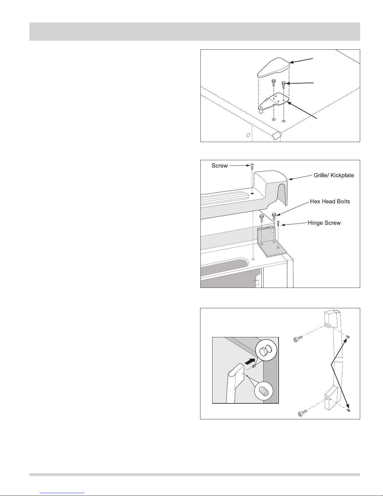
3. Lift plastic cover off upper hinge assembly.
(See Figure 2-28)
3. Using a 3/8” socket or wrench, extract the two bolts
securing the upper hinge to the unit frame.
4. Remove kickplate.
5. Using a 3/8” socket or wrench, extract the two bolts
securing the lower hinge to the unit frame. Use a
phillips head screwdriver to extract the remaining
screw from the lower hinge assembly.
(See Figure 2-29).
7. Lift the door assembly off of the unit frame.
Hinge Plate
Figure 2-28. Top Hinge Removal
Figure 2-29. Bottom Hinge Removal
Door Handle Mounting Instructions
For some installations the door handle may need to be
removed. (See Figure 2-30)
To remove the door handle:
1. Remove screw cover plates by pushing in and
sliding the screw cover plate off of the door handle.
2. Using a phillips head screwdriver, extract the screws
securing the door handle to the door assembly.
3. Push upwards until the screw button assembly is free
of the dovetail inside the handle assembly.
Set Screws
Figure 2-30. Handle Removal
2-15
Page 24
Section 2 Installation Information
Notes
2-16
Page 25
Section 3 Mechanical Control
Temperature Control
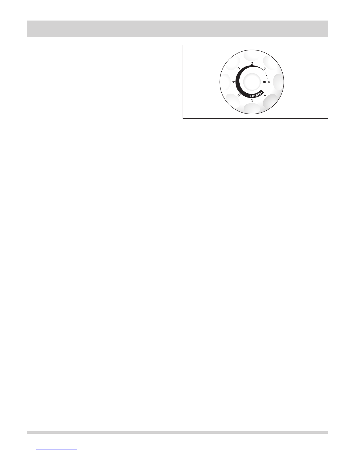
The temperature control is located inside the refrigerator
compartment. The temperature is factory preset to
provide satisfactory food storage temperatures. However,
the temperature control is adjustable to provide a range
of temperatures for your personal satisfaction. If a
colder temperature is desired, turn the temperature
control knob toward COLDEST and allow several hours
for temperatures to stabilize between adjustments.
Figure 3-1. Control Knob
Defrost Timing
An automatic 30 minute defrosting period is initiated
after every 12 hours of compressor running time. During
the defrosting period, a thermostat will switch the
defrost heater off after the frost on the evaporator has
melted. The defrost thermostat closes at 10ºF and opens
at 50ºF.
3-1
Page 26
Section 3 Electronic Control
Notes
3-2
Page 27
Section 4 Refrigeration
NOTE
Instructions given here are furnished as a guide.
Persons attempting to use these instructions to make
repairs to the sealed refrigeration system should have
a working knowledge of refrigeration and previous
training on sealed system repair, and an EPA
certification for servicing refrigeration systems.
IMPORTANT
Effective July 1, 1992, the United States clean air act
governs the disposal of refrigerants such as R-134a.
Therefore, when discharging or purging the sealed
system use an EPA approved refrigerant recovery
system as outlined in the final rule on the protection
of stratospheric ozone and refrigerant recycling, which
was published in the Federal Register May 14, 1993.
NOTE
Electrolux Home Products Inc. does not permit the use
of recovered refrigerant in the servicing of our products
for in-warranty and out-of-warranty repairs or for
products covered by service contracts. Therefore, only
new refrigerant or refrigerant that has been reclaimed
back to new specifications by a refrigerant
manufacturer is to be used.
Definitions
Recovery:
To remove refrigerant in any condition from a system
and store it in an external container without necessarily
testing or processing it in any way.
Recycling:
To clean refrigerant for reuse by oil separation and
single or multiple passes through devices, such as
replaceable core filter-driers, which reduce moisture,
acidity and particulate matter. This term usually applies
to procedures implemented at the field job site or at a
local service shop.
Safety Warnings
Compressor Testing
Whenever testing a compressor, extreme caution
should be used to prevent damaging the terminals. A
compressor with a damaged terminal or a grounded
winding can expel a terminal from its insulated housing
when the compressor is energized. If this happens, a
mixture of refrigerant and oil will be released that could
be ignited by an external heat source (open flame,
heater, etc.). Also, if there is air in the system when this
happens, a spark at the compressor shell could ignite the
refrigerant and oil mixture.
Charging Sealed Systems
Overcharging a refrigeration system with refrigerant can
be dangerous. If the overcharge is sufficient to immerse
the major parts of the motor and compressor in liquid
refrigerant, a situation has been created which, when
followed by a sequence of circumstances can lead to the
compressor shell seam separating.
A hydraulic block occurs, preventing the compressor from
starting. This condition is known as locked rotor. Electric
current continues to flow through the compressor motor
windings which become, in effect, electric resistance
heaters. The heat produced begins to vaporize the
excess refrigerant liquid causing a rapid increase in
system pressure. If the compressor protective devices
fail, the pressure within the system may rise to extremes
far in excess of design limits. Under these conditions,
the weld seam around the compressor shell can separate
with explosive force, spewing oil and refrigerant vapor
which could ignite.
To eliminate this exceedingly rare but potential hazard,
never add refrigerant to a sealed system. If refrigerant is
required, evacuate the existing charge and recharge with
the correct measured amount of the refrigerant specified
for the system.
Reclaim:
To reprocess refrigerant to new product specifications by
means which may include distillation, will require
chemical analysis of the refrigerant to determine that
appropriate product specifications are met. This term
usually implies the use of processes or procedures
available only at a reprocessing or manufacturing facility.
4-1
Page 28
Section 4 Refrigeration
Soldering
WARNING
Wear approved safety glasses when working
with or on any pressurized system or equipment.
Have an approved dry type fire extinguisher
handy when using any type of gas operated
torch.
1. All joints to be soldered must have proper fit.
Clearance between tubes to be soldered should be
from .001” to .006”. It is not practical to actually
measure this; however, you do not want a dry fit or
loose fit. Tubing joints should overlap about the
distance of their diameter except for restrictor tubes,
which should be inserted 1.25”.
2. Clean all joint areas with fine steel wool or
preferably an abrasive cloth, such as grit cloth
No. 23 or Scotch-Brite.
3. Apply a thin film of liquid flux recommended for
silver soldering to surfaces to be joined and to
surfaces immediately adjacent to joint.
CAUTION
During application of heat, use wet cloths to
prevent heat from conducting to areas other
than the soldered joint. Use a sheet of metal
or torch guard pad as a heat deflector to keep
flame away from inflammable materials and
painted surfaces.
Basic Components
The basic components of a refrigerator/freezer are a
compressor, condenser, evaporator, heat exchanger
(capillary tube and suction line) and drier.
Refrigerant Cycle
The refrigerant cycle is a continuous cycle that occurs
whenever the compressor is in operation. Liquid
refrigerant is evaporated in the evaporator by the heat
that enters the cabinet through the insulated walls and
by the heat from product load and door openings. The
refrigerant vapor is then drawn from the evaporator,
through the suction line to the compressor. Compression
raises the pressure and temperature of the vapor in the
compressor and the vapor is then forced through the
discharge valve into the discharge line and into the
condenser. Air passing over the condenser surface
removes heat from the high pressure vapor which then
condenses to a liquid. The liquid refrigerant then flows
from the condenser to the evaporator through the small
diameter liquid line (capillary tube). Before it enters
the evaporator, the liquid refrigerant is sub-cooled in the
heat exchanger by the low temperature suction vapor
in the suction line. When refrigerant is added, the frost
pattern will improve, the suction and discharge
pressures will rise, the condenser will become hot and
the wattage will increase.
4. Align tubing so no stress is on joint. Do not move
tubing while solder is solidifying or leaks will result.
5. Use a torch of adequate capacity so joint can be
quickly heated with a minimum of heat travel to
other points. Use a good grade of silver solder.
6. Solder connections. If tubing is properly cleaned
and fluxed, solder will flow readily. Use only enough
solder to make a good bond.
7. Allow joint to cool, then wash exterior with water to
remove flux.
4-2
Page 29
Section 4 Refrigeration
Low/High Side Leak or Undercharge
A loss of refrigerant can result in any of the
following:
1. Excessive or continuous compressor operation.
2. Above normal freezer compartment temperature.
3. A partially frosted evaporator (depending on amount
of refrigerant loss).
4. Below normal freezer compartment temperature.
5. Low suction pressure (vacuum).
6. Low wattage.
The condenser will be “warm to cool”, depending on the
amount of refrigerant lost.
In the case of a low side refrigerant leak resulting in
complete loss of refrigerant, the compressor will run but
will not refrigerate. Suction pressure will drop below
atmospheric pressure and air and moisture will be drawn
into the system saturating the filter drier.
If there is reason to believe the system has operated for
a considerable length of time with no refrigerant and the
leak occurred in the low side of the system, excessive
amounts of moisture may have entered the system.
In such cases the two stage service Dryer Filter part
number 5303918288 and vacuum procedure listed under
Refrigerant Leaks need to be followed to prevent
repetitive service.
If a slight undercharge of refrigerant is indicated and no
leak can be found after a thorough leak test, the charge
can be corrected without changing the compressor.
If a high side leak is located and some refrigerant
remains in the system it is not necessary to change the
compressor.
Testing for Refrigerant Leaks
NOTE
The line piercing valve (clamp-on type) should be
used for test purposes only. It must be removed from
system after it has served its purpose.
If the system is diagnosed as short of refrigerant and the
system has not been recently opened, there is probably
a leak in the system. Adding refrigerant without first
locating and repairing the leak or replacing the
component will not permanently correct the difficulty.
The leak must be found. Sufficient refrigerant may have
escaped to make it impossible to leak test effectively.
In such cases, add a ¼” line piercing valve to the
compressor process tube. Add sufficient refrigerant
vapor to increase the pressure to 40 to 50 lb. per sq.
in. Check the low side for leaks. Run the compressor 2
or 3 minutes and check the high side for leaks. Recover
refrigerant using an EPA approved recovery system.
Compressor Oil Contamination
To check for contamination, obtain oil sample from old
compressor.
1. If the oil has burned odor, but no color change or
residue — follow instructions on page 4-5 “Installing
A New Compressor”.
2. If oil has a burned odor and a sugar or gritty feel as
well as showing signs of contamination (dark color),
follow instructions in next section, To Flush The
System. Remove as much of contamination as
possible from system before installing new
compressor and filter-drier.
CAUTION
NEVER install a new compressor without first
checking for possible system contamination.
NOTE
It is recommended that system be flushed with dry
Nitrogen. However, if refrigerant is used to flush the
system you must look at the serial plate to see what
type of refrigerant is used in the system. This is the
only refrigerant that can be used to flush the system
and it must be recovered.
4-3
Page 30
Section 4 Refrigeration
To Flush The System
CAUTION
Use extreme care when using Dry Nitrogen to
flush systems. Pressure in nitrogen cylinder
could be as high as 2000 psi. Nitrogen cylinder
must be equipped with approved pressure
regulator and pressure relief valve. Ensure that
your hoses have adequate ratings for pressure
involved and that all of your equipment is in
good condition. The end of the flushing hose
on this tank regulator must be equipped with
a hand shut-off valve (Robinair No. 40380).
Close hand shut-off valve and adjust nitrogen
regulator to correct pressure before proceeding
with flushing procedure.
To Use Dry Nitrogen To Flush The System:
1. Remove compressor and filter-drier. Connect process
coupling to outlet tube of condenser.
2. Fasten cloth over other end of coil to prevent old oil
from spraying over room.
3. Connect hand shut-off valve on flushing hose to
process coupling.
4. Slowly open hand shut-off valve and allow nitrogen
to flow through condenser until discharge is clear.
CAUTION
DO NOT exceed 300 Psi.
To Use Refrigerant To Flush The System:
CAUTION
Refrigerant used for flushing must be recovered
into a recovery system. Meter amount of
refrigerant used for flushing with your charging
cylinder. DO NOT OVERFILL THE BAG.
1. Disconnect the suction and discharge lines from the
compressor and remove the filter-drier. Connect
process coupling to outlet and inlet tube of
condenser.
2. Connect hose to outlet process coupling and
charging cylinder. Connect another hose to inlet
coupling and recovery system.
3. Open charging cylinder and allow refrigerant to flow
through condenser until discharge into bag is clear.
NOTE
The line piercing valve (clamp-on type) should be
used for test purposes only. It must be removed from
system after it has served its purpose.
4. Disconnect capillary tube from evaporator. Flush
evaporator in same manner as condenser.
5. Flush cap tube. This is only possible if you have
proper service valve adapter.
6. Reassemble system.
5. Disconnect cap tube from evaporator. Flush
evaporator in same manner as condenser.
CAUTION
DO NOT exceed 150 Psi.
6. Flush cap tube. This is only possible if you have
proper service valve adapter.
CAUTION
DO NOT exceed 300 Psi.
7. Reassemble system.
4-4
Page 31
CAUTION
Section 4 Refrigeration
Installing a New Compressor
NOTE
Entirely new compressors have been developed or use
with R-134a and Ester oil refrigeration systems. Both
compressor and electric motor have been modified.
Old compressors intended for R-12 refrigerant must not
be used for new systems charged with R-134a.
Replacement of compressor and installation of filter-drier
must be done in a continuous sequence so system is
exposed to atmosphere no longer than necessary.
All replacement compressors are shipped with rubber
plugs in the suction, discharge and process tubes and
contain the correct oil charge and a holding charge of
inert gas. Compressors have a low-side process tube
attached to the compressor shell. A high-side process
tube is attached to the filter-drier.
WARNING
Do not operate reciprocating compressor when
charging liquid refrigerant into system through
its process tube.
Replacement compressors for refrigerators/freezers may
have an oil cooler even if the original compressor did
not. If the product is not equipped for an oil cooler,
leave the plastic caps in place and install the compressor
connecting only to the suction and discharge lines of the
new compressor.
NOTE
The following instructions are generalized to help the
technician understand the procedures of sealed
system repairs. See Section 5 Component Teardown
on the exact steps of accessing the components of the
refrigeration system.
A new compressor which is cold (e.g. after having been
kept in a cold service van) should be left to warm to the
surrounding temperature before the plugs on the
compressor connections are removed. This will help
prevent condensation from forming in the oil and the
compressor. Also, avoid opening the system when any
of the components or lines are cold.
NOTE
Release holding charge (release slowly to avoid oil
discharge) on new compressor to ensure there is no
leak in seam or tubing. Reinstall rubber plug.
1. Disconnect electrical supply to refrigerator/freezer.
2. Remove compressor access panel.
3. Remove all components needed to pull the
compressor assembly from the unit.
4. Pull compressor assembly straight out.
5. Recover refrigerant by using EPA approved
recovery system.
NOTE
Before installing the replacement compressor remove the
discharge plug and check for the pop sound of the inert
gas leaving the compressor.
DO NOT use compressor if you do not hear this
sound.
If the compressor checks OK, reinstall the plug. Do not
remove any of the plugs again until the compressor is in
position and you are ready to braze the lines.
CAUTION
On R-134a systems, compressor must NOT
be left open to atmosphere for more than 10
minutes to prevent moisture contamination of
oil.
If low-side process tube is too short, silver solder four
inch piece of tubing onto process tube at this time.
6. Remove leads from compressor motor terminals.
7. Remove mounting clips and washers.
8. After refrigerant is completely recovered, cut
suction and discharge lines as close to compressor
as possible. Leave only enough tubing to pinch off
and seal defective compressor. Plug or tape any
open system tubing to avoid entrance of moisture
and air into system. Remove inoperable
compressor and transfer mounting parts to new
compressor.
9. Install new compressor in exact same manner as
original compressor.
4-5
Page 32
Section 4 Refrigeration
10. Reform both suction and discharge lines to align
with new compressor. If they are too short, use
additional lengths of tubing. Joints should overlap
0.5” to provide sufficient area for good solder joint.
Clean and mark area where tubing should be cut.
Cut tubing with tubing cutter. Work as quickly as
possible to avoid letting moisture and air into the
system.
11. Solder all connections according to soldering
procedure.
12. Remove original filter-drier.
CAUTION
DO NOT unbraze old filter-drier from system.
This will vaporize and drive moisture from
desiccant back into system. The old filter-drier
should be cut out of system.
13. Install new filter-drier at condenser outlet.
14. Evacuate and charge system using recommended
procedure described under Evacuating and
Recharging.
15. Reconnect compressor terminal leads in
accordance with refrigerator wiring diagram.
16. Reassemble unit.
Condenser Replacement
NOTE
The following instructions are generalized to help the
technician understand the procedures of sealed
system repairs. See Section 5 Component Teardown
on the exact steps of accessing the components of the
refrigeration system.
1. Disconnect electrical supply to refrigerator/freezer.
2. Remove compressor access panel.
3. Recover refrigerant by using EPA approved
recovery system.
4. Remove condenser fan mounting screws.
5. Unplug fan motor harness located in back of fan
motor.
6. Remove fan motor and fan blade.
7. After refrigerant is completely recovered,
disconnect inlet and discharge lines from condenser.
8. Lift front of condenser and pull out of retainers
mounted to the drain pan.
9. Remove old condenser out the back of cabinet.
10. Install replacement condenser.
11. Remove original filter-drier.
CAUTION
DO NOT unbraze old filter-drier from system.
This will vaporize and drive moisture from
desiccant back into system. The old filter-drier
should be cut out of system.
12. Install new filter-drier at condenser outlet.
13. Evacuate and charge the system using
recommended procedure described under Evacuating
and Recharging.
14. Reassemble unit.
4-6
Page 33
Section 4 Refrigeration
Filter-Drier Installation
Any time the sealed system is opened and the
refrigerant charge is removed, the liquid line filter-drier
must be replaced and the system thoroughly evacuated
before replacing refrigerant.
CAUTION
DO NOT unbraze old filter-drier from system.
This will vaporize and drive moisture from
desiccant back into system. The old filter-drier
should be cut out of system.
NOTE
The following instructions are generalized to help the
technician understand the procedures of sealed
system repairs. See Section 5 Component Teardown
on the exact steps of accessing the components of the
refrigeration system.
1. Disconnect electrical supply to refrigerator/freezer.
2. Recover refrigerant by using EPA approved
recovery system.
3. Using a 3 cornered file, score a groove around
capillary tube as close to old filter-drier as possible.
Break capillary tube along score mark from
filter-drier.
4. Cut condenser outlet tube at filter-drier. Discard
filter-drier.
5. Thoroughly clean condenser outlet tube and
capillary tube.
6. Place inlet connection of filter-drier over condenser
tube approximately ¼” and solder.
7. Insert capillary tube input end into filter-drier outlet.
Do not allow tube to bottom against screen. Solder
carefully so that solder does not plug capillary tube.
8. Install process tube adapter to filter-drier.
9. Evacuate and charge system using the
recommended procedure described under Evacuating
and Recharging.
10. Reassemble unit.
Evaporator and Suction Line Replacement
NOTE
The following instructions are generalized to help the
technician understand the procedures of sealed
system repairs. See Section 5 Component Teardown
on the exact steps of accessing the components of the
refrigeration system.
1. Disconnect electrical supply to refrigerator/freezer.
2. Recover refrigerant by using EPA approved
recovery system.
3. Remove shelving.
4. Remove evaporator cover.
5. Remove evaporator from its installation position.
6. Cut or remove suction line from compressor.
7. Cut filter-drier from condensing unit.
CAUTION
DO NOT unbraze old filter-drier from system.
This will vaporize and drive moisture from
desiccant back into system. The old filter-drier
should be cut out of system.
8. Remove sealant from cabinet where suction line
enters.
9. Remove evaporator and suction line as one piece.
10. Install new evaporator with attached suction line.
11. Seal cabinet.
12. Install new filter drier at condenser outlet.
13. Evacuate and charge system using the
recommended procedure described under Evacuating
and Recharging.
4-7
Page 34
Section 4 Refrigeration
CAUTION
Check the serial plate for the correct refrigerant
type. It is extremely important to verify the
type of refrigerant in the system before starting
any sealed system repairs.
With the possible exception of the vacuum
pump, all service equipment that comes in
contact with R-134a during evacuation and
recharging must be dedicated. Accordingly,
R-134a will require a dedicated charging
cylinder, manifold gauge set, process tube
adapters, and hoses. Any residual mineral oil
on other tools (tubing cutter, etc.) must be
thoroughly cleaned off before using on R-134a/
Ester oil systems. It will be necessary to check
with the manufacturer of your vacuum pump for
refrigerant and oil compatibility issues.
If you use a vacuum pump with mineral oil to
evacuate an R-134a system, it is ABSOLUTELY
ESSENTIAL to have a shut-off valve between the
pump and your manifold gauge set as shown
on page 4-10. The hand valve must be closed
during all times when the vacuum pump is
not operating. This will prevent the migration
of mineral oil vapor into the R134a/Ester oil
system. If the vacuum pump should stop during
evacuation for any reason, the hand pump
shut-off valve must be closed immediately.
Insure that your refrigeration hoses are specified
for use with R-134a refrigerant. Research has
shown that compounds in standard refrigeration
hoses may enter sealed systems and ultimately
restrict the cap tube in an R-134a system.
Equipment Needed for Evacuation &
Recharging:
• Heated charging cylinder
• Standard 3-port manifold gauge set:
- 4 charging hoses
- Tee fitting with valve core stem removed
(Robinair No. 40396)
- Hand shut-off valve (Robinair No.40380)
• Two stage vacuum pump
• Process tube adapter kit (Robinair No.12458)
• Tubing cutter
• Pinch-off tool capable of making leak proof seal
• Complete brazing torch set
• Small 3-corner file
• Grit cloth or Scotch-Brite
• 45% silver solder and flux
• Heat Gun
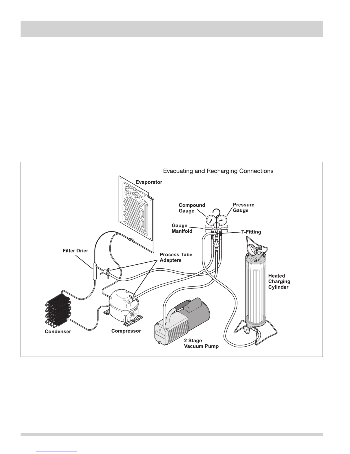
Installing Evacuation and Recharging
Equipment
1. Disconnect refrigerator/freezer from electrical supply.
2. If compressor was replaced, install correct sized
process tube adapter on process tube.
If compressor was not replaced, cut process tube
with tubing cutter leaving as much tube as possible
and install correct size process tube adapter.
3. Install correct sized process tube adapter on
high-side process tube.
4. Attach refrigeration service gauge manifold to
system in following order:
• Low-side (compound gauge) hose to suction
side process tube adapter.
• High-side (pressure gauge) hose to high-side
process tube adapter.
• Center port manifold hose before hand shut-off
valve to charging cylinder.
• Center port manifold hose after hand shut-off
valve to vacuum pump.
4-8
Page 35
Section 4 Refrigeration
WARNING
R-134a systems are particularly susceptible to
moisture contamination which can only be
prevented by evacuating the System for a
minimum of 30 minutes to attain a minimum
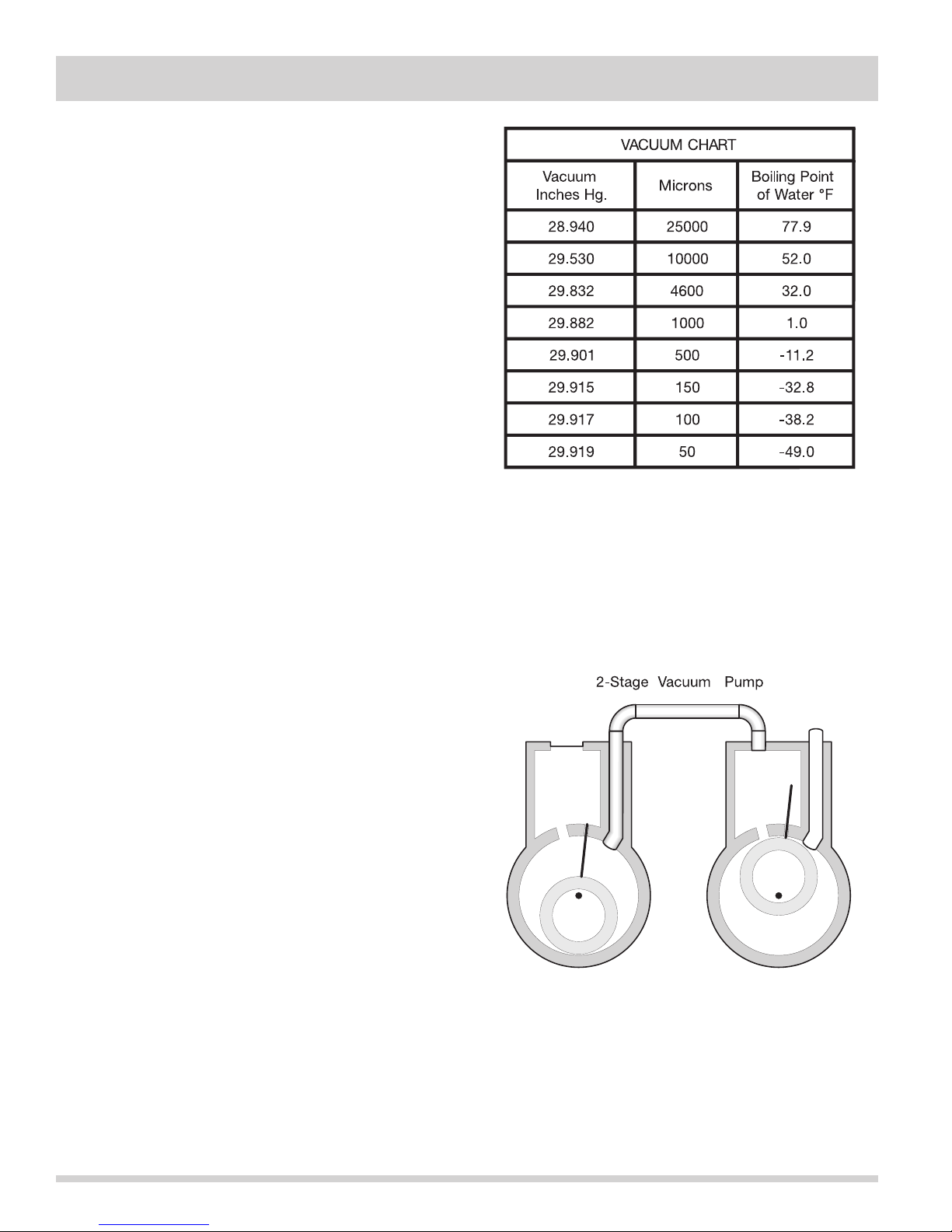
29.9 inch (500 micron or lower) vacuum.
Evacuating System
To achieve the required levels of evacuation, a properly
maintained two stage vacuum pump in good condition is
required. It is absolutely essential to maintain your
vacuum pump according to the manufacturer’s
instructions including required oil changes at the
recommended intervals. Vacuum pump oil should always
be changed after evacuating a contaminated system.
Vacuum pump performance should be checked
periodically with a micron gauge.
1. Make certain that charging cylinder valve, hand
shut-off valve, and manifold gauge valves are closed.
2. Start vacuum pump.
3. Open hand shut-off valve and slowly open both
manifold valves, turning counterclockwise, for two
full rotations.
CAUTION
If high vacuum equipment is used, just crack
both manifold valves for a few minutes and
then open slowly for the two full turns
counterclockwise. This will prevent the
compressor oil from foaming and being drawn
into the vacuum pump.
4. Operate vacuum pump for a minimum of 30
minutes to a minimum of 29.9” (500 micron)
vacuum.
5. Close hand shut-off valve to vacuum pump. Watch
compound gauge for several minutes. If reading
rises, there is a leak in the system, go to step 6. If
no leak is indicated, stop vacuum pump. System is
now ready for charging.
6. If a leak is indicated, stop vacuum pump and
introduce a small charge of refrigerant into system
by cracking valve on bottom of charging cylinder
until system is pressurized to 40 or 50 lbs psi.
7. Leak test low-side. Close compound gauge. Run
compressor for a few minutes and leak test
high-side. When leak is found, recapture refrigerant
using EPA approved recovery system. Repair and go
back to step 1.
Charging The System
CAUTION
Check the serial plate for the correct refrigerant
type. It is extremely important to verify the
type of refrigerant in the system before starting
any sealed system repairs. After charging the
system with liquid be certain to wait at least 5
minutes before starting the compressor to give
the refrigerant a chance to disperse throughout
the system. Otherwise the compressor could
be damaged by attempting to pump excessive
quantities of liquid.
Preparing The Charging Cylinder:
1. Make certain that hand shut-off valve to vacuum
pump is closed.
2. Close high-side manifold gauge valve.
3. Set charging cylinder scale to pressure indicated on
cylinder pressure gauge.
4. Observe refrigerant level in sight glass. Subtract
amount to be charged into system and note shut off
point.
5. Open charging cylinder valve slowly and allow
proper charge to enter system.
6. As soon as refrigerant in sight glass has gone down
to predetermined level, close charging cylinder valve.
WARNING
Disconnect the charging cylinder heater at this
time to prevent the cylinder pressure from
exceeding its maximum limits.
7. Allow system to sit for five minutes.
8. Turn on refrigerator compressor. Run compressor for
a few minutes and monitor system pressures.
9. When satisfied that the unit is operating correctly,
clamp the high-side process tube with the pinch-off
tool while the unit is still running.
4-9
Page 36
Section 4 Refrigeration
10. Slowly open the high-side manifold gauge valve
to allow the compressor to remove any refrigerant
trapped in the high-side hose and the process
fitting.
11. Close both of the manifold gauge valves. If the
high-side gauge reading rises, the pinch-off must be
corrected before proceeding.
12. Remove the high-side process tube adapter and
solder the process tube closed.
13. Clamp the low-side process tube with the pinch-off
tool while the unit is running. Remove the low-side
process tube adapter and solder the process tube
closed.
14. Check the process tubes for refrigerant leaks.
Final Leak Test
1. With the refrigerator/freezer turned OFF, leak test all
low-side system components.
2. Turn the unit ON and run until the condenser is
warm. Leak test the high-side system components.
4-10
Page 37
Section 4 Refrigeration
Verify Refrigerant Type In The System
CAUTION
R-134a and R-12 are completely incompatible.
Before starting any sealed system repair, it is
extremely important to check serial plate of
product to verify the type of refrigerant in the
system.
Dedicated Equipment
R-134a must not be mixed with other types of
refrigerants. R-134a must be recovered in dedicated
and properly identified recovery bags and tanks.
It will be necessary to check with the manufacturer of
your recovery equipment to determine R-134a
compatibility. Some recovery equipment manufacturers
have changeover instructions for switching between
refrigerant types. Protect yourself and your equipment
by following all manufacturer guidelines.
Also, ensure that your refrigeration hoses are specified
for use with R-134a refrigerant. Research has shown
that compounds in standard refrigeration hoses may
enter sealed systems and ultimately restrict the cap tube
in an R-134a system.
R-134a Refrigeration Systems
The sealed refrigeration system will consist of the same
basic components being utilized in the R-12 systems.
There is a 10% to 15% discharge pressure increase
using R-134a, with a 5% to 10% decrease in suction
pressure when compared to the same product with an
R-12 system operating at 90°F (32°C) ambient
temperature conditions. Lower suction pressures result
from the lower density of R-134a refrigerant which
effects refrigerant flow rate. R-134a systems commonly
operate in a 1”-2” vacuum on the suction side.
Products using R-134a refrigerant will generally have a
longer capillary tube to maintain a similar flow rate and
some models will have a larger condenser to reduce the
discharge pressures and lower start-up sound
transmission.
Miscibility of R-134a and Ester Oil
A special synthetic oil known as Ester oil is used as a
lubricant in refrigeration systems operating on R-134a.
Ester oils are produced from alcohols and fatty acids and
are available in several different variants. Ester oils have
a pleasant aroma reminiscent of fruit.
Ester oils generally include various types of additives for
improving certain properties such as viscosity,
temperature sensitivity, etc. These additives are often
aggressive, and skin contact with Ester oils should
therefore be avoided.
One of the most important requirements made on a
refrigerant system is that the oil mix with the refrigerant.
Since mineral oil and ordinary synthetic oil DO NOT mix
with R-134a, Ester oil is used for lubrication. Ester oil
dissolves in R-134a.
Ester oil is broken down by chlorine and cannot be
used with R-12 (R-12 contains chlorine) or any other
compound containing chlorine. Therefore, R-134a
refrigeration systems have virtually no tolerance for
chlorine molecules from CFC refrigerants (R-134a is an
HFC and contains no chlorine).
CAUTION
During R-134a service, it is extremely important
to avoid using equipment that may contain
residual amounts of mineral oil, CFC’s or HCFC’s
which could enter and contaminate the sealed
system.
4-11
Page 38
Section 4 Refrigeration
For example, hoses that were used for a refrigeration
system operating on R-12 may contain small quantities
of mineral oil which can block the capillary tube in a
system operating on R-134a. As little as one milligram
may be sufficient to cause a blockage. In addition,
sealed system components that have been used with
CFC systems must not be used with R-134a systems.
These components may contain residual amounts of
refrigerant and oil which could damage an R-134a
system.
At the earliest stage of development work on R-134a,
tests were carried out on a different type of synthetic
oil known as Poly-Alkaline Glycol (PAG). This oil is also
used in certain air conditioning systems for cars.
PAG and Ester oil DO NOT mix with one another. Service
equipment used for R-134a / Ester oil must not come
into contact with PAG.
Water In The Refrigeration System
Even in very small quantities, water in any refrigeration
system can cause the following problems:
• Ice plugs in capillary tubes.
• Copper plating in compressor.
• Reactions with organic materials in systems.
• Corrosion of metals.
To achieve the required 29.9 inch (500 micron) vacuum,
a properly maintained two-stage vacuum pump in good
condition is required. A two stage pump can reach a
deeper vacuum than a single stage because the exhaust
from the first pumping stage is discharged into the
second pumping stage. This means the second stage
begins pumping at a lower pressure so a lower ultimate
vacuum can be achieved.
R-134a and Ester oil will aggravate the problem of water
in the refrigeration system. Ester oil may react with
water vapor and is hygroscopic (it will absorb water if it
comes in contact with humid air). Water is also more
soluble in R-134a than R-12.
To minimize the water content whenever service work
is performed, the refrigeration system should always be
thoroughly evacuated through process tube adapters on
both the high and low sides of the system. Evacuation
must be for a minimum of 30 minutes to at least a 29.9
inch (500 micron) vacuum.
4-12
Page 39
Section 4 Refrigeration
Vacuum Pump Maintenance
It is absolutely essential to maintain your vacuum pump
according to the manufacturer’s instructions including
required oil changes at the recommended intervals.
Vacuum pump oil should always be changed after
evacuating a contaminated system. Vacuum pump
performance should be checked periodically with a
micron gauge.
Vacuum pump suppliers may or may not recommend
changing the vacuum pump oil to the same type that’s in
the system being evacuated. Some manufacturers may
recommend a vacuum pump that’s dedicated to R-134a
systems.
Robinair has stated that their current and discontinued
vacuum pump models, using mineral oil currently
specified for use in their vacuum pumps, can be used to
evacuate R-134a/Ester oil systems. Robinair also states
that it is acceptable to alternate between evacuating
R-12/mineral oil and R-134a/Ester oil systems without
adversely effecting the vacuum pump’s performance.
For other brands of vacuum pumps, check with the
manufacturer for restrictions and guidelines when using
with R-134a.
Refrigerant Leaks
A system with R-134a and Ester oil will become
saturated with moisture much faster than a system with
R-12 and mineral oil. If your leak was in the low side of
the refrigeration system when the compressor is
running the pressure in the low side will go into a
vacuum. As additional refrigerant leaks out the system
will go deeper into a vacuum. The system running in
this vacuum will allow air and moisture to be pulled into
the sealed system. The moisture pulled in can then be
mixed in to the Ester oil in the compressor.
If the product has had a low side leak you will need to
install the two stage service dryer filter part number
5303918288. You must heat the crankcase area of the
compressor using a heat gun on the high heat setting
throughout the 30 minutes you are running your
vacuum pump to pull a vacuum on the system. Every 4
to 5 minutes while you are running your vacuum pump
and heating the crankcase area, shake the compressor.
By heating the crankcase you are heating the oil in the
compressor. This will drive the moisture out of the oil.
By shaking the compressor this will allow the moisture
to come to the top of the oil faster so the vacuum pump
can remove the moisture from the system.
CAUTION
If you use a vacuum pump with mineral oil to
evacuate an R-134a system, it is ABSOLUTELY
ESSENTIAL to have a shut-off valve between
pump and your manifold gauge set as shown
on page 4-10. The hand valve must be closed
during all times when vacuum pump is not
operating. This will prevent migration of
mineral oil vapor into R134a/Ester oil system.
If vacuum pump should stop during evacuation
for any reason, the hand pump shut-off valve
must be closed immediately.
Electrolux Home Products does not approve the use of
the Sweep Charge for sealed system repair. This method
of servicing sealed systems is often used to repair
products in the field. The Sweep Charge does not
adequately remove moisture from the oil in the
compressor. In a R-134a system you will need to replace
the compressor if the product has had a low side leak
and you are servicing with the Sweep Charge
procedure.
R-134a refrigerant molecules are smaller than R-12
molecules. This means that R-134a will pass more minor
leaks and the rate of flow will be greater than for R-12.
Therefore, it is now more important than ever to follow
good brazing practices. Use a good grade of silver
solder. A 45% silver solder is recommended.
4-13
Page 40
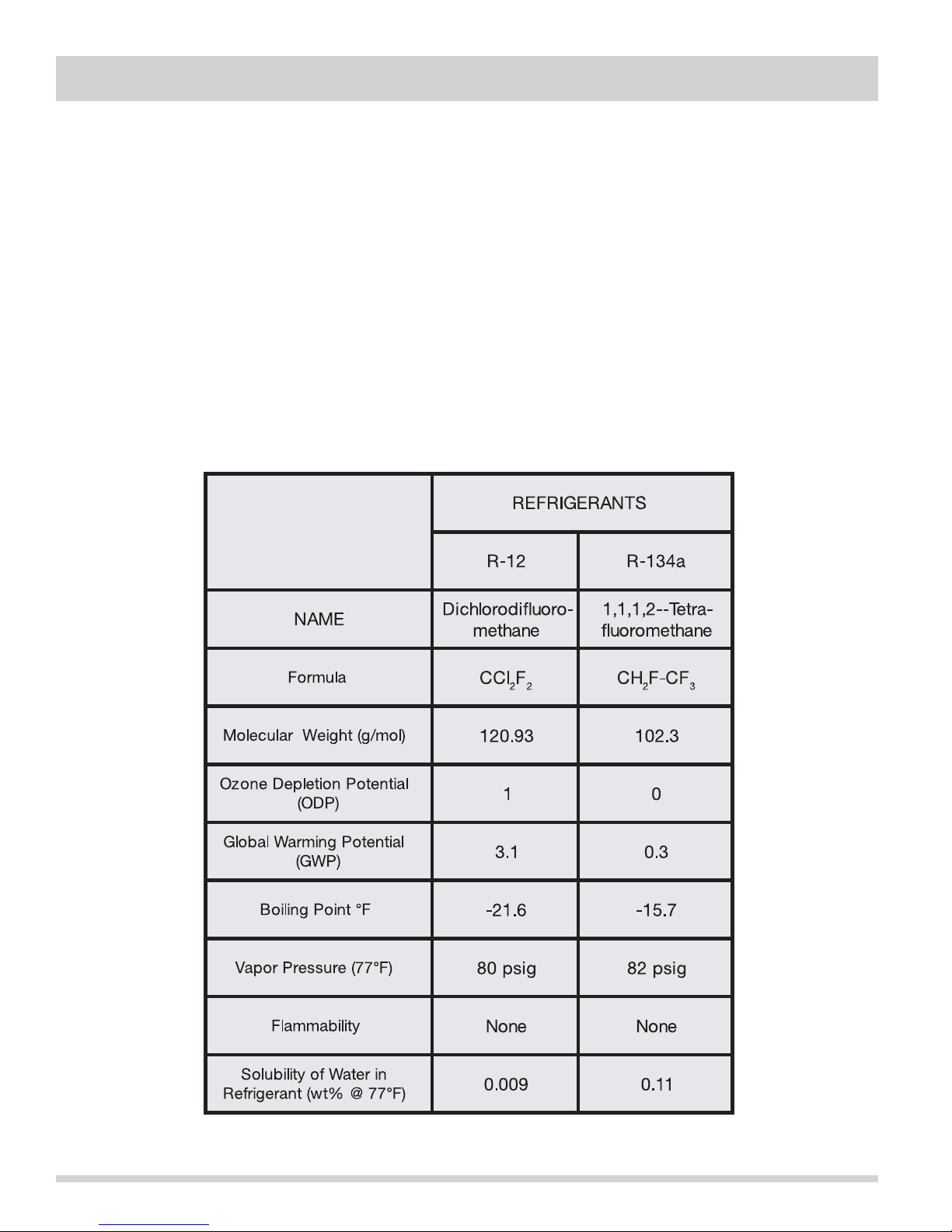
Section 4 Refrigeration
Leak Detection
R-134a system leaks can be pinpointed by means of an
electronic leak detector or by bubble solution.
Electronic leak detectors for R-134a service are currently
available from several manufacturers. The least
expensive models are non-selective detectors that will
detect any type of emission or vapor present, regardless
of its chemical composition. Some non-selective
detectors designed for use with R-12 may have a much
lower sensitivity when used with R-134a. However, newly
designed detectors with good R-134a sensitivity are now
available. Be sure to consult with the manufacturer
before selecting or using a non-selective detector with
R-134a.
Halogen-specific detectors use a specialized sensor that
allows detection of compounds containing chlorine,
fluorine, bromine, and iodine without being activated
by other species. The major advantage of this type
of detector is a reduction in the number of “nuisance
alarms”. Halogen-specific detectors are generally more
expensive than non-selective detectors but feature
higher sensitivity.
R-134a properties
The properties of R-134a are very similar to those of
R-12. The principal data for the two refrigerants are
shown in the chart below.
4-14
Page 41
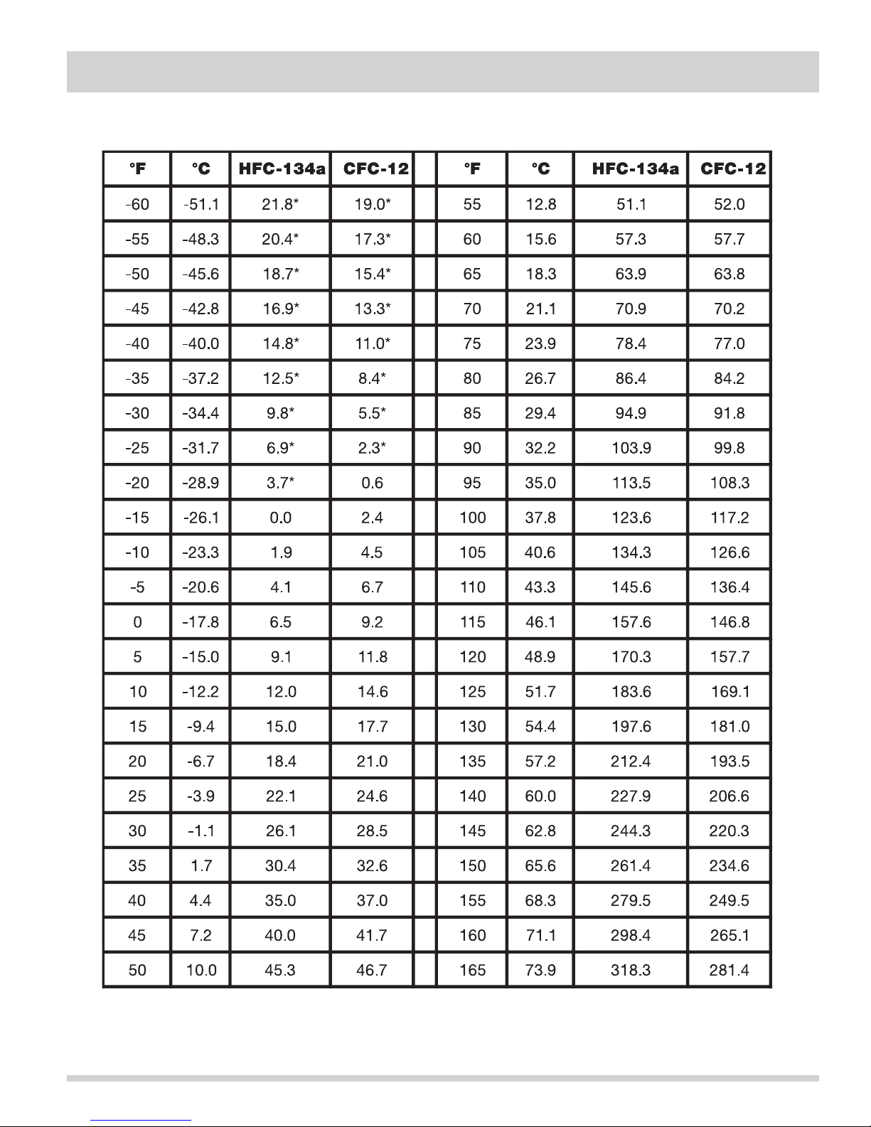
Section 4 Refrigeration
HFC-134a, CFC-12 Pressure Temperature Chart
4-15
Page 42

Section 4 Refrigeration
Inhalation Toxicity
HFC-134a poses no acute or chronic hazard when it is
handled in accordance with DuPont recommendations
and when exposures are maintained at or below the
DuPont Acceptable Exposure Limit (AEL) of 1,000 ppm
(8 and 12 hour Time-Weighted Average or TWA).
An AEL is an airborne exposure limit established by
DuPont scientists that specifies time-weighted average
(TWA) airborne concentrations to which nearly all
workers may be repeatedly exposed without adverse
effects. The AEL for HFC-134a has the same value as
the Threshold Limit Values (TLVs) established for
CFC-12 and HCFC-22. TLVs are established by the
American Conference of Governmental and Industrial
Hygienists (ACGIH).
However, inhaling high concentrations of HFC-134a vapor
may cause temporary central nervous system depression
with narcosis, lethargy and anesthetic effects. Other
effects that may occur include dizziness, a feeling of
intoxication and a loss of coordination. Continued
breathing of high concentrations of HFC-134a vapors
may produce cardiac irregularities (cardiac sensitization),
unconsciousness, and with gross overexposure, death.
Intentional misuse or deliberate inhalation of HFC-134a
may cause death without warning. This practice is
extremely dangerous.
If you experience any of the initial symptoms, move to
fresh air and seek medical attention.
Cardiac Sensitization
If vapors are inhaled at a concentration of 75,000 ppm,
which is well above the AEL, the heart may become
sensitized to adrenaline, leading to cardiac irregularities
and, possibly, to cardiac arrest. The likelihood of these
cardiac problems increases if you are under physical or
emotional stress.
Medical attention must be given immediately if exposed
to high concentrations of HFC-134a. DO NOT treat with
adrenaline (epinephrine) or similar drugs. These drugs
may increase the risk of cardiac arrhythmia and cardiac
arrest. If the person is having difficulty breathing,
administer oxygen. If breathing has stopped, give
artificial respiration.
Spills or Leaks
If a large release of vapor occurs, such as from a
large spill or leak, the vapors may concentrate near the
floor or low spots and displace the oxygen available for
breathing, causing suffocation.
Evacuate everyone until the area has been ventilated.
Use blowers or fans to circulate the air at floor level. DO
NOT re-enter the affected area unless you are equipped
with a self-contained breathing apparatus or unless an
area monitor indicates that the concentration of
HFC-134a vapors in the area is below the AEL.
Always use self-contained breathing apparatus or an
air-line mask when entering tanks or other areas where
vapors might exist. Use the buddy system and a
lifeline. Refer to the Material Safety Data Sheet (MSDS)
for HFC-134a for more information.
HFC-134a vapors have a slightly sweet odor that can be
difficult to detect. Therefore, frequent leak checks and
the installation of permanent area monitors may be
necessary in enclosed spaces. Refer to ASHRAE
Standards 15 and 34 for refrigeration machinery rooms.
To ensure safety when working with HFC-134a in
enclosed areas:
1. Route relief and purge vent piping (if present)
outdoors, away from air intakes.
2. Make certain area is well ventilated, using auxiliary
ventilation if needed to move vapors.
3. Make sure area is clear of vapors prior to beginning
work.
4. Install air monitoring equipment to detect leaks.
Skin and Eye Contact
At room temperature, HFC-134a vapors have little or no
effect on the skin or eyes. However, in liquid form,
HFC-134a can freeze skin or eyes on contact, causing
frostbite. Following contact, soak the exposed area in
lukewarm water, not cold or hot. If medical treatment
cannot begin immediately, apply a light coat of a
nonmedicated ointment, such as petroleum jelly. If the
exposed area is in a location where the presence of the
ointment would be awkward, such as on the eye, apply
a light bandage. In all cases of frostbite, seek medical
attention as soon as possible.
4-16
Always wear protective clothing when there is a risk of
exposure to liquid HFC-134a. Where splashing is
possible, always wear eye protection and a face shield.
Page 43

Section 4 Refrigeration
Combustibility of HFC-134a
HFC-134a is nonflammable at ambient
temperatures and atmospheric pressure. However, tests
have shown HFC-134a to be combustible at pressures
as low as 5.5 psi (139.3 kPa absolute) at 177°C (350°F)
when mixed with air at concentrations generally greater
than 60% volume air. At lower temperatures, higher
pressures are required for combustibility.
(HCFC-22 is also combustible at pressures above
atmospheric in the presence of high air concentrations).
Test results and calculations have shown:
• At ambient temperature, all concentrations of
HFC-134a in air are nonflammable at pressures
below 15 psi (205 kPa absolute).
• Combustible mixtures of air and HFC-134a will not
form when liquid HFC-134a is pumped into closed
vessel if initial air pressure in vessel is limited to
one atmosphere absolute and final pressure is
limited to 300 psi (2,170 kPa absolute). If initial air
pressure is greater than one atmosphere,
combustible mixtures may form as tank is filled.
Based on above information, the following
operating practices are recommended:
Leak Testing
• Equipment should NEVER be leak tested with a
pressurized mixture of HFC-134a and air. HFC-134a
may be safely pressured with dry nitrogen.
Filling and Charging Operations
• Before evacuating cylinders or refrigeration
equipment, any remaining refrigerant should be
removed by recovery system.
• Vacuum pump discharge lines should be free of
restrictions that could increase discharge pressures
above 15 psi (205 kPa) and result in formation of
combustible mixtures.
• Cylinders or refrigeration equipment should
normally be evacuated at start of filling, and should
never be filled while under positive air pressure.
• Final pressures should not exceed 300 psi
(2,170 kPa).
• Filled cylinders should periodically be analyzed
for air (nonabsorbable gas or NAG).
Refrigerant Recovery Systems
Efficient recovery of refrigerant from equipment or
containers requires evacuation at the end of the
recovery cycle. Suction lines to a recovery compressor
should be periodically checked for leaks to prevent
compressing air into the recovery cylinder during
evacuation. In addition, the recovery cylinder pressure
should be monitored, and evacuation stopped in the
event of a rapid pressure rise indicating the presence of
noncondensable air. The recovery cylinder contents
should then be analyzed for NAG, and the recovery
system leak checked if air is present. DO NOT
continue to evacuate a refrigeration system that has a
major leak.
Bulk Delivery and Storage
• Tanks should normally be evacuated at start of
filling, and should never be filled while under
positive air pressure.
• Tank pressure should never be allowed to exceed
300 psi (2,170 kPa) when filling with HFC-134a.
Relief devices on either tanks or HFC-134a supply
system usually prevent this.
• Tank pressures should be monitored routinely.
• Air lines should never be connected to storage tanks.
Thermal Decomposition
HFC-134a vapors will decompose when exposed to
high temperatures from flames or electric resistance
heaters. Decomposition may produce toxic and irritating
compounds, such as hydrogen fluoride. The pungent
odors released will irritate the nose and throat and
generally force people to evacuate the area. Therefore,
it is important to prevent decomposition by avoiding
exposure to high temperatures.
4-17
Page 44
Section 4 Refrigeration
Notes
4-18
Page 45
Section 5 Component Teardown
Component Teardown
This section explains how to access and remove components from an All Refrigerator Pro and/or an All Freezer Pro
unit, and has been arranged in such a way as to simulate which components would need to be removed first in
order to gain access to other components. When following a component removal procedure, it may be necessary to
reference another component removal procedure listed earlier in this section.
IMPORTANT
Before continuing, please take note of the WARNINGS and CAUTIONS below.
WARNING
- If it is necessary to remove an All Refrigerator Pro and/or an All Freezer Pro unit from its
installation, use proper lifting techniques as units are heavy and could fall resulting in serious injury
or death. Pulling a unit from its installation should only be performed by a trained authorized
service technician or installer.
- To avoid electric shock, power to an All Refrigerator Pro and/or an All Freezer Pro unit must be
disconnected whenever accessing/ removing components powered by electricity or components
near other electrical components.
- After service is completed, be sure all safety-grounding circuits are complete, all electrical
connections are secure, and all access panels are in place.
- If unit was used prior to service, the compressor assembly will be hot. Wear protective gloves and
the appropriate safety gear when working with compressors.
- If removing a door from a unit, remember that the doors are heavy. If a door were to fall, it could
cause serious personal injury.
CAUTION
- Metal edges may be sharp. Use caution and wear appropriate safety equipment when servicing
evaporators and condensers to avoid personal injury.
- If working in the compressor area, remember that compressor and tubing may be hot.
5-1
Page 46
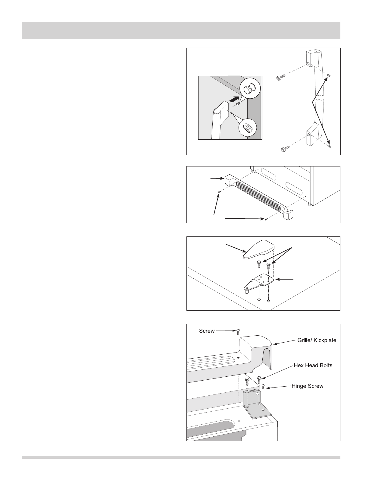
Section 5 Component Teardown
Exterior Components
Door Handle Removal
The door handle is secured with setscrews to the
handle mounting shoulder screws that are fastened
into the front of the door assembly.
All Refrigerator-Pro
To remove the handle, use a 3/32” allen wrench and
extract the setscrew located in each handle standoff.
Pull handle assembly from door assembly.
(See Figure 5-1)
Use a 5/32” allen wrench to extract the screw
located inside the handle standoff, that secures the
handle standoff to the handle.
Kickplate Removal
The kickplate is secured with two screws to the lower
front of the unit.
To remove the kickplate, extract the screw from each
end of the kickplate with a phillips head screwdriver.
(See Figure 5-2)
Door Hinge and Door Assembly Removal
The door assembly is secured to the unit frame by an
upper and lower hinge assembly.
To remove the door assembly:
1. Gently lay freezer on its back on a soft clean
surface.
2. Lift plastic cover off upper hinge assembly.
(See Figure 5-3)
3. Using a 3/8” socket or wrench, extract the two bolts
securing the upper hinge to the unit frame.
4. Remove kickplate.
5. Using a 3/8” socket or wrench, extract the two bolts
securing the lower hinge to the unit frame. Use a
phillips head screwdriver to extract the remaining
screw from the lower hinge assembly.
7. Lift the door assembly off of the unit frame.
Kickplate
Set Screws
Figure 5-1. Handle Removal
Screws
Figure 5-2. Kickplate Removal
Hinge
Cover
Figure 5-3. Upper Hinge Removal
Bolts
Upper
Hinge
5-2
Figure 5-4. Lower Hinge Removal
Page 47
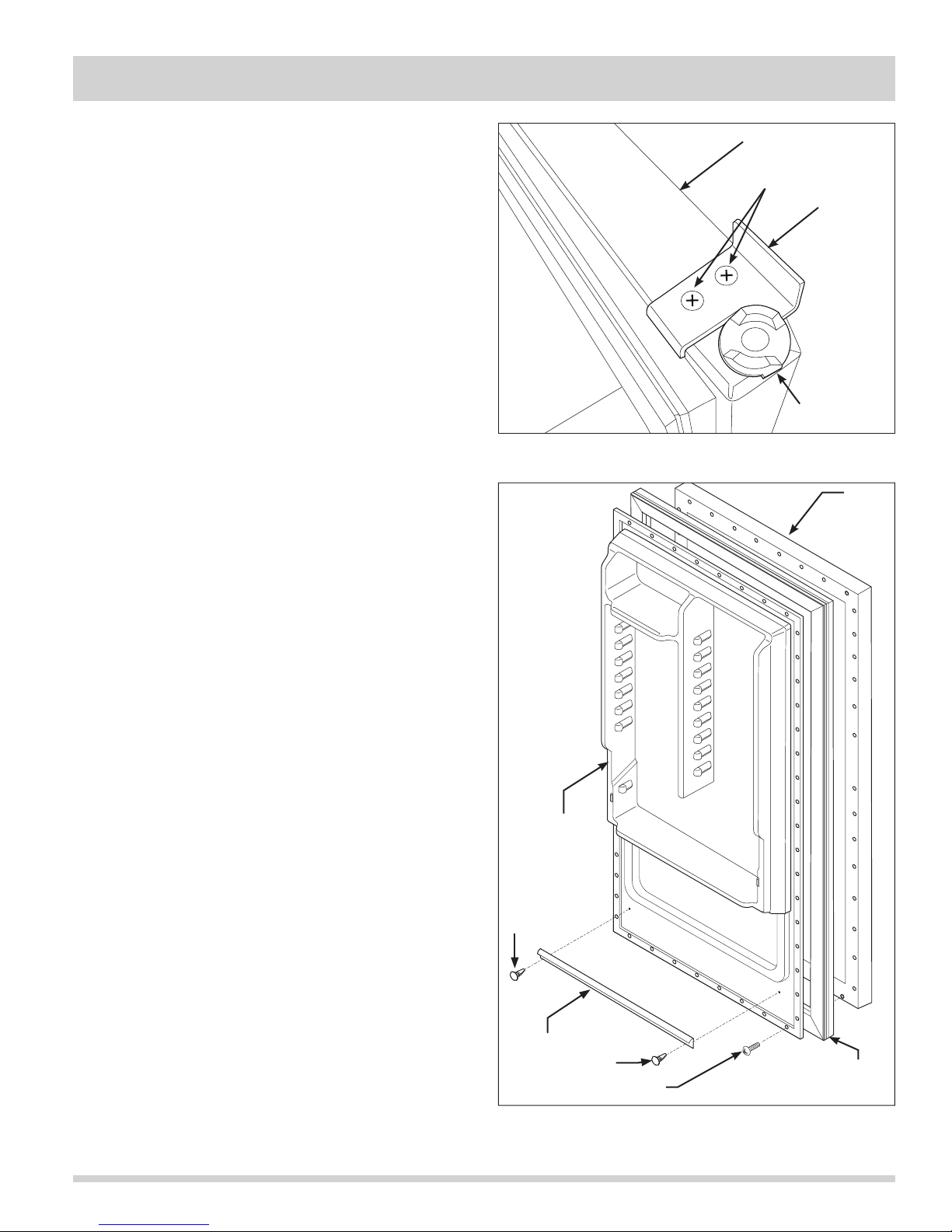
Section 5 Component Teardown
All Refrigerator-Pro
Door Stop Assembly Removal
The door stop is secured to with two screws the
underside of the door assembly.
To remove the door stop:
1. Remove door from unit.
2. Extract the two screws securing the door stop to the
bottom of the door assembly. (See Figure 5-5)
Door Gasket and Inner Panel Removal
The inner panel of the door assembly is secured with
screws that pass through the inner panel and fasten
into the door assembly. The door gasket has an inner
lip that is pressed between the inner panel and the door
assembly and is secured in position when the inner panel
screws are fastened to the door assembly. The inner
panel does not have to be completely removed to extract
the door gasket from the door assembly.
To remove the door gasket:
1. Lift the inside edge of the door gasket to access the
inner panel screws.
2. Loosen the inner panel screws until the door gasket
can be pulled out from under the inner panel.
(See Figure 5-6)
3. Continue loosening screws around door assembly
until door gasket is free.
4. To remove the inner panel, extract all screws from
the outside edge of the inner panel and remove from
unit.
5. The secondary gasket is secured with two retaining
clips that snap into the inner door panel. Pry out
the two retaining clips with a small putty knife, using
caution not to damage the inner door panel. The
secondary gasket is now free.
Door Frame
Screws
Door Stop
Hinge Bearing
Figure 5-5. Door Stop Removal
Outer
Door
Panel
Inner Panel
Clip
Secondary
Gasket
Figure 5-6. Inner Panel and Door Gasket Removal
Clip
Screw
Door
Gasket
5-3
Page 48
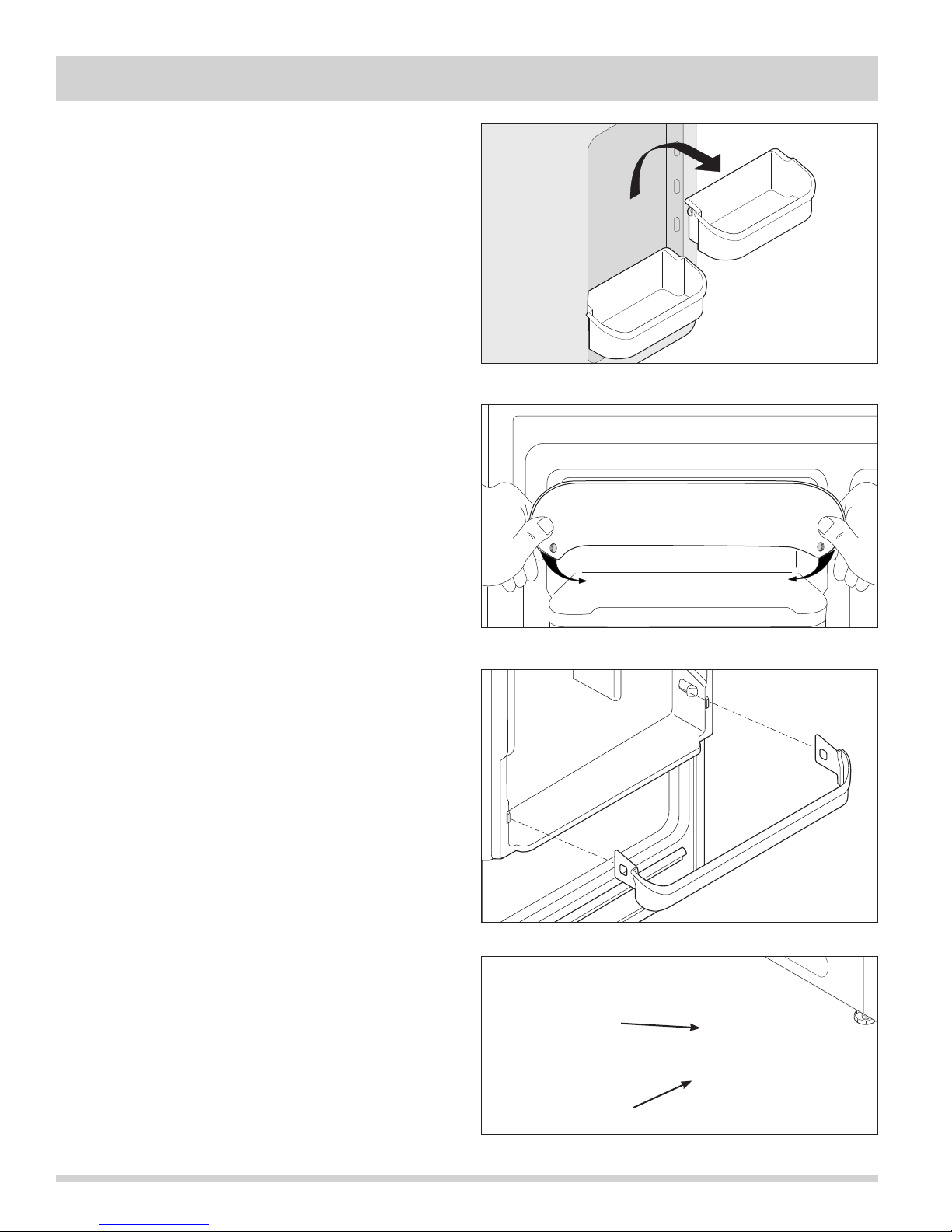
Section 5 Component Teardown
Door Storage Components
Adjustable Door Bins Removal
There are four two liter door bins that can be arranged
as needed by the user.
To remove a two liter door bin, lift the bin straight up
until it is free of the supports molded into the door liner,
then pull from unit. (See Figure 5-7)
Dairy Door Removal
The dairy door has a hole on each side that fi ts over
molded pins in the door liner.
To remove the dairy door:
1. Open dairy door.
2. Grab the dairy door on each side and flex the outer
edge inwards until the door is free of the pins in the
door liner, then pull from door. (See Figure 5-8)
Gallon Door Bin Removal
All Refrigerator-Pro
Figure 5-7. Adjustable Door Bin Removal
The gallon door bin has slots on each end that fi t over
molded slots in the door liner.
To remove the gallon door bin, bend the inside lip of the
gallon door bin away from the supports molded into the
door liner while pulling out of the door. (See Figure 5-9)
Door Switch Removal
The door switch is mounted inside a hole in the cabinet
base along the lower left hand side.
(See Figure 5-10)
To remove the door switch:
1. Disconnect unit from power supply.
2. Remove kickplate.
3. Reach into the access hole next to the door switch
and disconnect the electrical leads from the door
switch terminals.
4. Press in on the retaining latch on the switch body
and push switch through hole in cabinet base.
Figure 5-8. Dairy Door Removal
Figure 5-9. Door Lock Removal
5-4
Access Hole
Door Switch
Figure 5-10. Door Switch Removal
Page 49
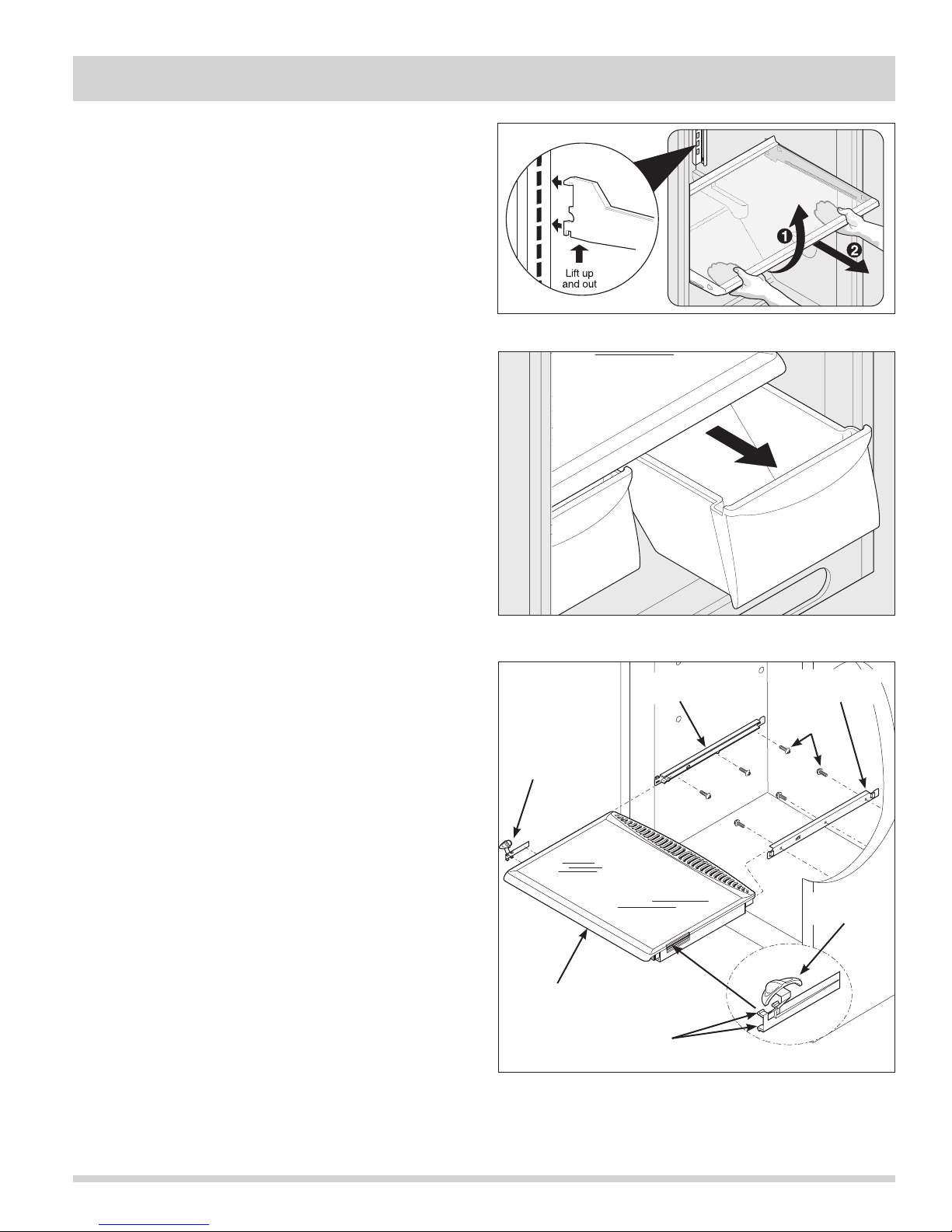
Section 5 Component Teardown
All Refrigerator-Pro
Interior Components
Adjustable Interior Shelving Removal
Multi-position adjustable interior shelves can be moved
to any position for larger or smaller packages. The
cantilever shelves are supported at the back of the
refrigerator. (See Figure 5-11) Replace the shelf by
inserting the hooks at rear of the shelf into the wall
bracket. Lower the shelf into the desired slots and lock
into position.
To remove the shelf assemblies:
1. Lift front edge up.
2. Pull shelf out.
Crisper Drawer Removal
The crisper drawers are removed by grabbing the
drawer by the handle and pulling the drawers out of
the unit. (See Figure 5-12)
Figure 5-11. Interior Shelving Removal
Crisper Cover
To replace the crisper drawers, line up the plastic lip on
the outside edge of the crisper drawer with the slots
located under the crisper cover, then slide crisper
drawers back into unit.
Crisper Cover Assembly Removal
The crisper cover assembly slides into a slot formed in
the left and right hand supports that are secured with
screws to the liner sidewall.
To remove the crisper cover assembly:
1. Remove crisper drawers from unit.
2. Reach under the crisper cover and lift up on the
crisper cover glass insert. Remove glass insert
from unit. (See Figure 5-13)
3. Grab the crisper cover assembly from the front, lift
upwards until front of crisper cover clears the front
lip of the crisper cover supports then pull straight
out.
4. The humidity damper control is separated from the
crisper cover by using a flat bladed screwdriver from
the inside of the crisper cover, and prying the top
retaining latches of the damper control off of the
crisper cover. Push the retaining latches through
until the damper control is free from crisper cover.
5. To remove the crisper cover supports, extract the
three screws securing each crisper cover support
to the liner sidewall.
Figure 5-12. Crisper Drawer Removal
Crisper Cover
Support LH
Humidity
Control LH
Glass Insert
Crisper Cover
Assembly
Retaining
Latches
Figure 5-13. Crisper Cover Assembly Removal
Crisper Cover
Support RH
Screws
Humidity
Control LH
5-5
Page 50
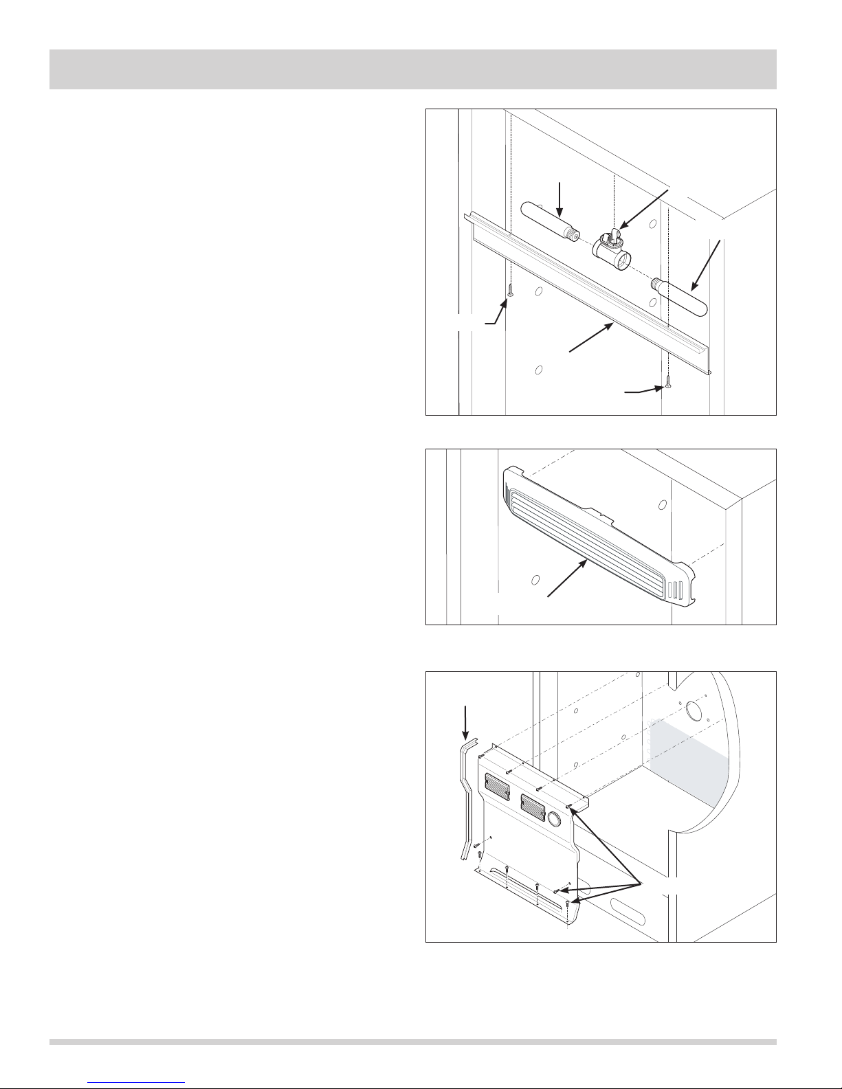
Section 5 Component Teardown
Light Shield Removal
To remove the light shield, extract the two screws
securing the light shield to the compartment ceiling.
Light Fixture Removal
The light fixture is secured with retaining latches into the
interior cabinet ceiling behind the light shield.
(See Figure 5-14)
To remove the light fixture:
All Refrigerator-Pro
Light Bulb
Light Fixture
Light Bulb
1. Disconnect unit from power supply.
2. Remove light bulb by turning counter-clockwise.
3. Pull down on the front of the light fixture while
turning the fixture a quarter turn to release the
retaining latches.
4. Disconnect wire leads from light fixture terminals.
Baffle Plate Removal
To remove the baffle plate, with one hand grab the
baffle plate from the center and pull back while with
the other hand, reach behind to disengage the retaining
latches. (See Figure 5-15)
Evaporator Cover Removal
The evaporator cover is secured with screws to the
back wall and bottom of the freezer compartment. The
evaporator cover has a gasket on each side to create
proper airflow in the compartment. (See Figure 5-16)
To remove the evaporator cover:
1. Disconnect unit from power supply.
2. Remove the cantilever shelves.
3. Remove the crispers and crisper supports.
4. Using a phillips head screwdriver, extract the ten
(10) screws securing the evaporator cover to the
refrigerator compartment.
5. Pull the thermostat knob from thermostat shaft.
6. Carefully pull the evaporator cover away from the
back wall enough to access the wire harness
connections to the light fixtures and thermostat. Use
caution not to damage the gaskets on both sides of
the evaporator cover.
7. From behind the evaporator cover, disconnect the
wire leads from the light fixture terminals.
8. Compress the thermostat spring clip then pull the
thermostat from the back of the evaporator cover.
Evaporator cover may now be removed from unit.
Screw
Light Shield
Screw
Figure 5-14. Light Shield and Fixture Removal
Baffle Plate
Figure 5-15. Baffle Plate Removal
Gasket
1 of 2 shown
Screws
Figure 5-16. Evaporator Cover Removal
5-6
Page 51
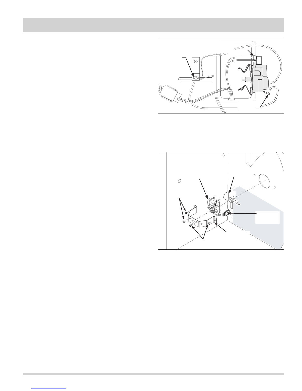
Section 5 Component Teardown
All Refrigerator-Pro
Thermostat Control Removal
The evaporator cover does not need to be completely
removed to access the thermostat control or the wire
harness connections, however, removing the evaporator
cover from the unit will make the task easier.
To remove the thermostat control:
1. Follow steps 1-8 from the previous page on
removing the evaporator cover.
2. Extract the screw securing the sensor tube to the
back wall of the cabinet interior. (See Figure 5-17)
3. Disconnect the 2 wire leads from the top of the
thermostat control.
4. Disconnect the ground wire lead from the thermostat
control. Thermostat control is now free.
Evaporator Fan Assembly Removal
The evaporator fan assembly consists of the fan motor
mount bracket, fan motor and fan blade. Two screws
secure the fan motor to the fan motor mount bracket.
The evaporator fan assembly is then secured with two
screws to the back wall of the freezer compartment.
(See Figure 5-18)
Electrical
Sensor Tube
Screw
Figure 5-17. Thermostat Control Removal
Fan Motor
Screws
Connection
Ground
Wire
Fan Blade
To remove the evaporator fan assembly:
1.
Disconnect unit from power supply.
2. Remove the cantilever shelves.
3. Remove the crispers and crisper supports.
4. Remove the evaporator cover.
5. Remove wires from retaining clips mounted on the
fan motor mounting bracket. Disconnect the
electrical leads of fan motor at quick disconnect.
6. Using a 5/16” socket or nut driver, extract the two
hex head screws securing the fan motor mounting
bracket to the back wall of the unit.
7. Separate the fan motor from the mounting bracket
by extracting the two hex head screws securing the
fan motor to mounting bracket.
8. Pull fan blade from fan motor shaft.
Electrical
Connection
Fan Motor
Screws
Figure 5-18. Evaporator Fan Assembly Removal
Mounting
Bracket
5-7
Page 52
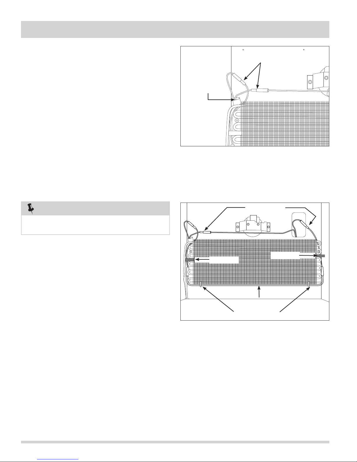
Section 5 Component Teardown
Defrost Thermostat Removal
All Refrigerator-Pro
The defrost thermostat is secured with a retaining clip to
the upper left corner of the evaporator assembly. The
defrost thermostat and wire harness connections may be
accessed without completely removing the evaporator
cover. The top of the evaporator cover may be pulled
away from the rear of the cabinet interior enough to
remove the defrost terminator and disconnect the wire
harness connections. (See Figure 5-19)
To remove the defrost thermostat:
1. Disconnect unit from power supply.
2. Remove the cantilever shelves.
3. Remove the crispers and crisper supports.
4. Remove the evaporator cover.
5. Disconnect the defrost thermostat wire leads from
the wire harness. (See Figure 5-19)
6. Pull the defrost thermostat off of the evaporator
inlet tubing.
NOTE
Refrigerator defrost thermostat must be
installed on the evaporator inlet tube.
Disconnect Here
Defrost
Thermostat
Figure 5-19. Defrost Thermostat Removal
Disconnect Here
Defrost Heater Removal
The defrost heater is secured with two aluminum straps
to the bottom tube of the evaporator assembly.
To remove the defrost heater:
1. Disconnect unit from power supply.
2. Remove the cantilever shelves.
3. Remove the crispers and crisper supports.
4. Remove the evaporator cover.
5. Disconnect the defrost heater wire leads from the
wire harness. (See Figure 5-20)
6. Release the aluminum straps securing the defrost
heater to the bottom of the evaporator assembly.
7. Remove the styrofoam insulators from both sides of
the evaporator.
8. Pull defrost heater from evaporator assembly.
Styrofoam
Defrost Heater
Aluminum Straps
Figure 5-20. Defrost Heater Removal
Styrofoam
5-8
Page 53
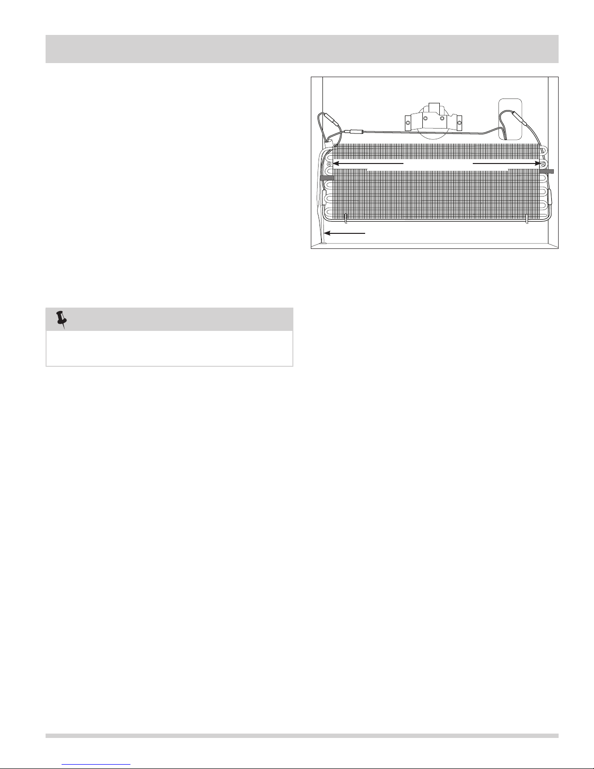
Section 5 Component Teardown
All Refrigerator-Pro
Evaporator Removal
The evaporator sets upon the two screw standoffs
mounted to the back wall of the freezer compartment.
Two pieces of styrofoam are pressed between the
evaporator assembly and the sidewalls of the unit,
securing the assembly in position. (See Figure 5-21)
To remove the evaporator:
1. Disconnect unit from power supply.
2. Remove the cantilever shelves.
3. Remove the crispers and crisper supports.
4. Remove the evaporator cover.
5. Remove the styrofoam insulators from both sides of
the evaporator.
6. Remove the defrost thermostat and defrost heater.
7. Recover refrigerant by using EPA approved
recovery system.
Heat Exchanger
Figure 5-21. Evaporator Removal
Screw Standoffs
NOTE
Whenever the sealed system is opened the
filter-drier must be replaced.
8. Remove the filter-drier.
9. Cut suction line about 1” from compressor.
10. Straighten the tubing, remove the foam sleeve, and
carefully feed the heat exchanger through the
cabinet while pulling up on the evaporator.
5-9
Page 54
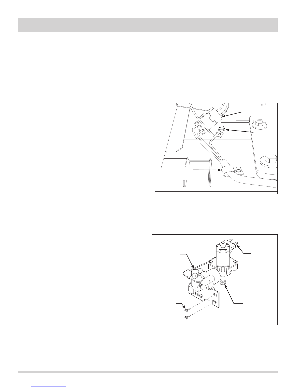
Section 5 Component Teardown
Compressor Area Components
All Refrigerator and All Freezer-Pro
Models
The compressor area components for the All Refrigerator
and All Freezer-Pro Units are similar in layout and have
the same access and removal steps. However, the part
numbers for items in the compressor area may differ
between the all refrigerator and all freezer models.
All Refrigerator And All Freezer-Pro
Power Cord Removal
The power cord enters the compressor area on the lower
left side and is secured to the compressor mounting
plate with a P-clamp and screw.
To remove the power cord:
1. Pull unit from its installation position to access the
rear compressor area. Disconnect power from unit.
2. Using a phillips head screwdriver, extract the four
screws securing the compressor area shield to the
rear of the unit. Remove shield.
3. Using a 1/4” socket or wrench, extract the screw
securing the P-clamp to the compressor mounting
plate. (See Figure 5-22)
4. Using a 1/4” socket or wrench, extract the screw
securing the ground wires to the compressor
mounting plate.
5. Disconnect power cord from the wire harness at the
quick disconnect. Remove power cord from unit.
Water Valve Removal (if equipped)
The water valve is secured with two screws to the
right hand side of the unit behind the compressor
area shield.
P-Clamp
and Screw
Figure 5-22. Power Cord Removal
Household
Inlet
Electrical
Connection
Ground
Screw
Electrical
Connection
To remove the water valve:
1. Pull unit from its installation position to access the
rear compressor area.
2. Using a phillips head screwdriver, extract the four
screws securing the compressor area shield to the
rear of the unit. Remove shield.
3. Disconnect water valve from household water
supply. (See Figure 5-23)
4. Using fingers, disconnect the icemaker water line
from water valve.
5. Using a 1/4” socket or wrench, extract screws
securing water valve to unit frame.
6. Disconnect electrical connections from terminals of
water valve.
5-10
Screws
Figure 5-23. Power Cord Removal
To Ice
Maker
Page 55
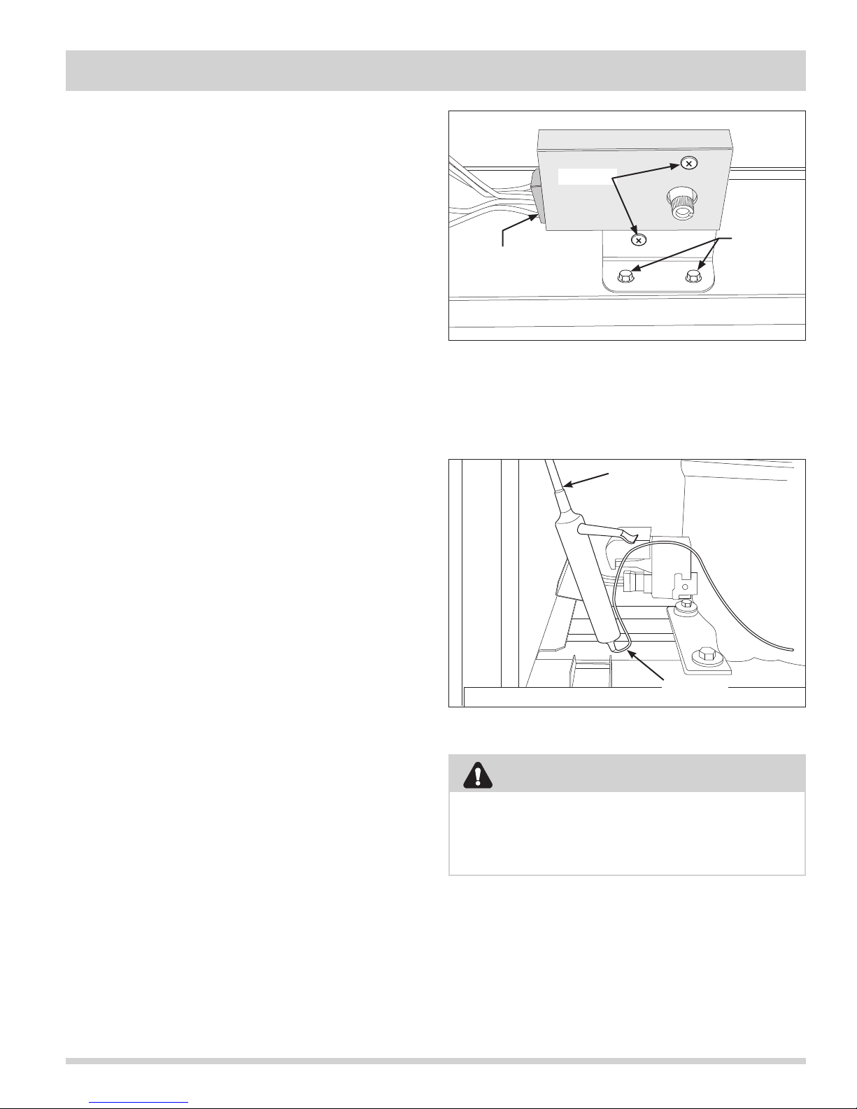
Section 5 Component Teardown Section 5 Component Teardown
All Refrigerator And All Freezer-Pro
Defrost Timer Removal
The defrost timer is mounted to a bracket which is
secured to the bottom of the base tray with two 1/4”
bolts. (See Figure 5-24)
To remove the defrost timer:
Screws
Cover
1. Pull unit from its installation position to access the
rear compressor area. Disconnect power from unit.
2. Extract the screws securing the fiber board cover to
the unit frame and remove from unit.
3. Extract the upper screw first securing the defrost
timer cover to the mounting bracket. Remove cover.
4. Extract lower screw. Pull defrost timer from
mounting bracket.
5. Disconnect wire harness connector from defrost
timer.
6. Extract the two bolts with a 1/4” socket or wrench to
remove the mounting bracket to the base tray.
Filter-Drier Removal
The filter-drier is located in the compressor area on the
left side of the compressor. (See Figure 5-25)
To remove the filter-drier:
1. Pull unit from its installation position to access the
rear compressor area. Disconnect power from unit.
2. Extract the screws securing the fiber board cover to
the unit frame and remove from unit.
3. Recover refrigerant by using EPA approved
recovery system.
4. Using a 3 cornered file, score a groove around
capillary tube as close to old filter-drier as possible.
Break capillary tube along score mark from
filter-drier.
5. Cut condenser outlet tube at filter-drier. Discard
filter-drier.
6. Thoroughly clean condenser outlet tube and
capillary tube.
7. Place inlet connection of filter-drier over condenser
tube approximately ¼” and solder.
8. Insert capillary tube input end into filter-drier outlet.
Do not allow tube to bottom against screen. Solder
carefully so that solder does not plug capillary tube.
9. Install process tube adapter to filter-drier.
10. Evacuate and charge system using the recommended procedure described under Evacuating and
Recharging in the Refrigeration section.
11. Reassemble unit.
Bolts
Electrical
Connection
Figure 5-24. Defrost Timer Removal
Cut Here
Cut Here
Figure 5-25. Filter-Drier Removal
CAUTION
On R-134a systems, the system must NOT be
left open to the atmosphere for more than 10
minutes to prevent moisture contamination of
compressor oil.
5-11
Page 56
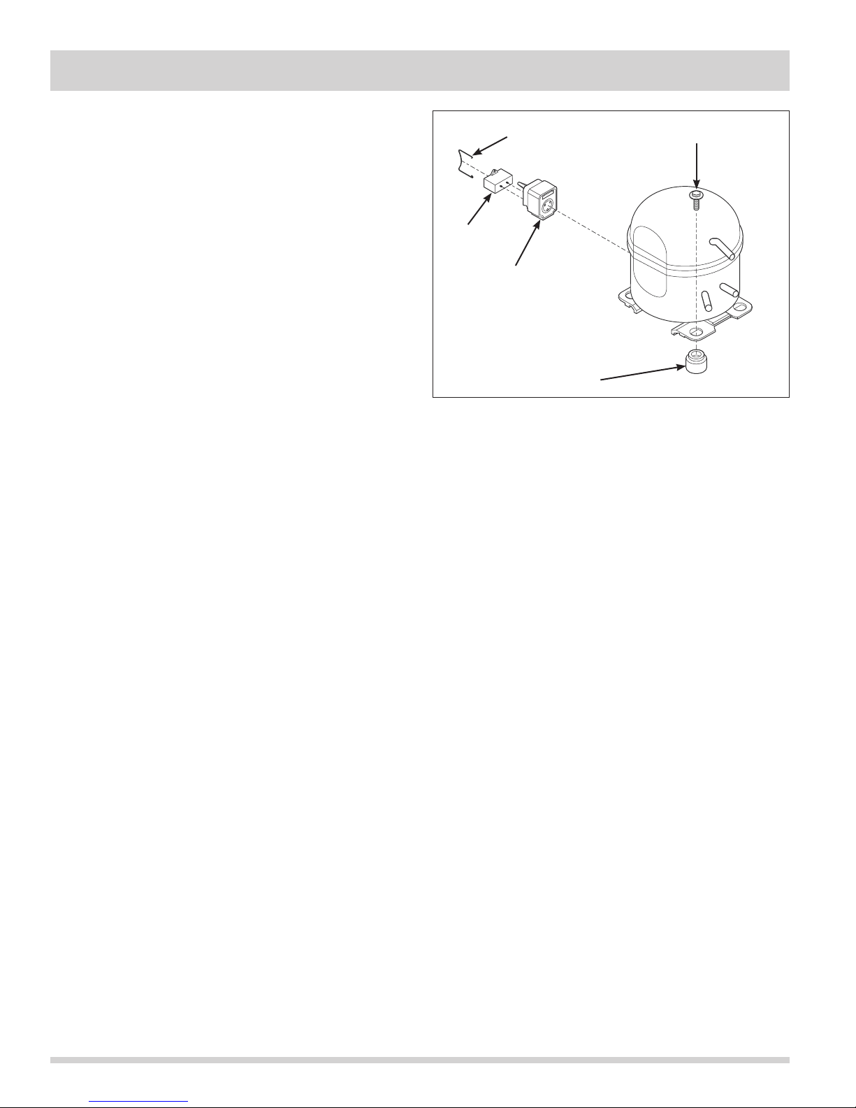
Section 5 Component Teardown
Compressor Removal
The compressor sits on four grommets and is secured
with four screws to the compressor mounting plate.
(See Figure 5-26)
To remove the compressor:
All Refrigerator And All Freezer-Pro
Spring Wire
Bolt
1. Pull unit from its installation position to access the
rear compressor area. Disconnect power from unit.
2. Extract the screws securing the compressor shield to
the unit frame and remove from unit.
3. Using a small flat bladed screwdriver, release the
locking tab from the wire harness connection and
disconnect from compressor controller.
4. Using a needlenose pliers, remove spring wire
holding the controller to the compressor.
5. Recover refrigerant by using EPA approved
recovery system.
6. Using a 7/16” socket, remove the (4) bolts, one in
each corner, holding the compressor to the base.
(See Figure 5-26)
7. After refrigerant is completely recovered, cut
suction and discharge lines as close to compressor
as possible. Leave only enough tubing to pinch off
and seal defective compressor. Plug or tape any
open system tubing to avoid entrance of moisture
and air into system. Remove inoperable compressor
and transfer mounting parts to new compressor.
8. Install new compressor inexact same manner as
original compressor.
9. Reform both suction and discharge lines to align with
new compressor. If they are too short, use additional lengths of tubing. Joints should overlap 0.5” to
provide sufficient area for good solder joint. Clean
and mark area where tubing should be cut.
10. Cut tubing with tubing cutter. Work quickly to avoid
letting moisture and air into system.
11. Reassemble unit.
Capacitor
Controller
Grommet
Figure 5-26. Compressor Components
5-12
Page 57
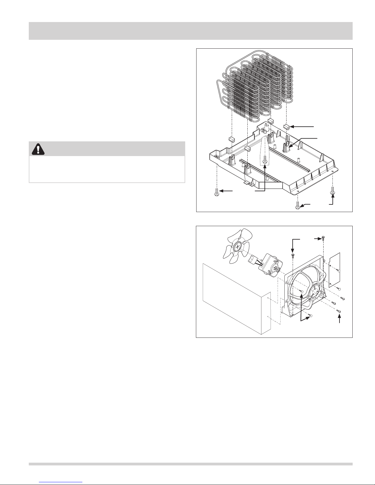
Section 5 Component Teardown
All Refrigerator And All Freezer-Pro
Drain Pan Removal
The drain pan is secured with four screws to the
bottom of the unit frame.
To remove the drain pan:
1. Pull unit from its installation position to access the
rear compressor area. Disconnect power from unit.
2. Extract the screws securing the compressor shield to
the unit frame and remove from unit.
3. The rear of the unit may need to be raised to access
the drain pan screws.
Grommet
Retainer
CAUTION
Use caution when tilting a freezer unit. Use
sturdy blocking materials that will not allow the
freezer to rock or tip over when servicing unit.
4. Using a short phillips head screwdriver, extract the
two screws securing the drain pan to the bottom of
the unit frame. (See Figure 5-27)
5. Position unit to access the front of the unit. Remove
kickplate.
6. The front of the unit may need to be raised to
access the drain pan screws.
7. Using a short phillips head screwdriver, extract the
two screws securing the drain pan to the bottom of
the unit frame. (See Figure 5-27)
8. Allow the drain pan to drop down. Pull drain tube
from drain pan.
9. Pull condenser tubes out of the retainers mounted to
the drain pan. Drain pan may now be removed from
the unit.
Condenser Fan Motor Removal
The condenser fan motor is secured with three screws
to the condenser fan motor bracket. Two hooks and two
screws at the base of the condenser fan motor bracket
secure the assembly to the unit base. (See Figure 5-28)
To remove the condenser fan motor:
1. Pull unit from its installation position to access the
rear compressor area. Disconnect power from unit.
2. Extract the screws securing the compressor shield to
the unit frame and remove from unit.
3. Disconnect wire harness from the wire leads of
condenser fan at quick disconnect.
4. Remove the four drain pan screws. Allow the drain
pan to drop from its installation position.
Screws
Screws
Figure 5-27. Condenser Drain Pan Removal
Bolts
Air Divider
Plastic
Retainers
Figure 5-28. Condenser Fan Motor Removal
5. With a needle nose pliers, reach behind air dividers
and compress the plastic retainers while pushing
them out of the condenser fan mounting bracket.
Remove air dividers.
6. Using a 1/4” socket or wrench, extract the two
bolts securing fan mounting bracket to unit frame.
7. Using a phillips head screwdriver, extract the three
screws securing the fan motor to the fan mounting
bracket.
8. Pull fan motor and fan blade out from behind the
mounting bracket. Remove fan blade by pulling the
fan blade from the motor shaft.
Screws
5-13
Page 58
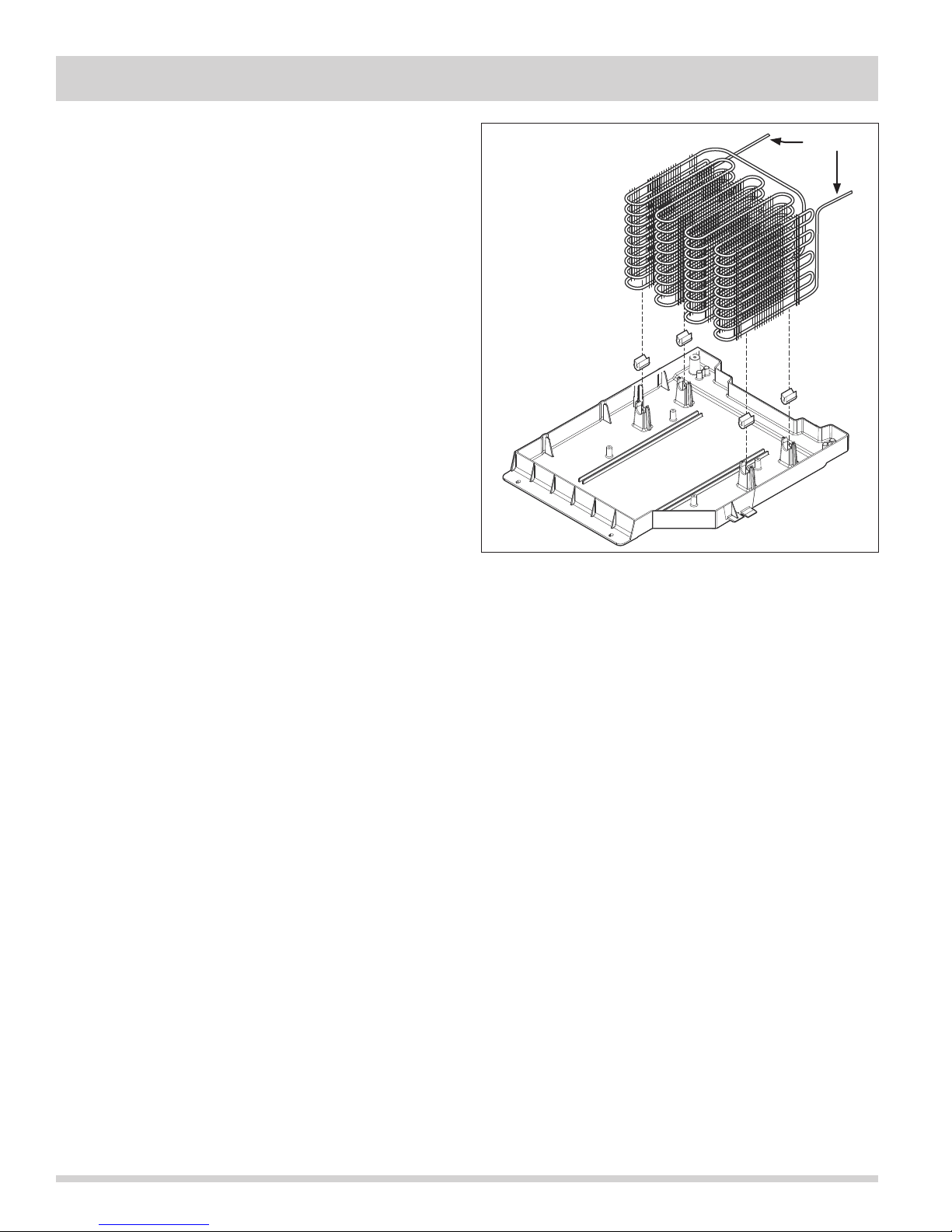
Section 5 Component Teardown
All Refrigerator And All Freezer-Pro
Condenser Coil Removal
The condenser coil is mounted to the drain pan by four
retaining clips.
To remove the drain pan:
1. Pull unit from its installation position to access the
rear compressor area. Disconnect power from unit.
2. Extract the screws securing the compressor shield to
the unit frame and remove from unit.
3. Recover refrigerant by using EPA approved recovery
system.
4. Remove condenser fan assembly from unit.
5. Disconnect inlet and outlet lines from condenser coil.
(See Figure 5-29)
6. The front of the unit will need to be raised to access
the drain pan screws.
7. Using a short phillips head screwdriver, extract the
four screws securing the drain pan to the bottom of
the unit frame.
8. Allow the drain pan to drop down. Pull drain tube
from drain pan.
9. Pull condenser tubes out of the retainers mounted to
the drain pan. Remove condenser from unit.
10. Replace old filter-drier after installing the new
condenser coil.
Cut Here
Figure 5-29. Condenser Coil Removal
5-14
Page 59
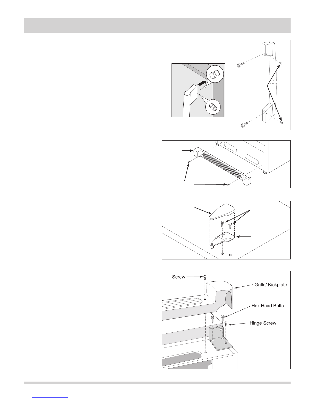
Section 5 Component Teardown
All Freezer-Pro
Freezer Exterior Components
Door Handle Removal
The door handle is secured with setscrews to the handle
mounting shoulder screws that are fastened into the
front of the door assembly.
To remove the handle, use a 3/32” allen wrench and
extract the setscrew located in each handle standoff.
Pull handle assembly from door assembly.
(See Figure 5-30)
Use a 5/32” allen wrench to extract the screw located
inside the handle standoff, that secures the handle
standoff to the handle.
Kickplate Removal
The kickplate is secured with two screws to the lower
front of the unit.
To remove the kickplate, extract the screw from each
end of the kickplate with a phillips head screwdriver.
(See Figure 5-31)
Figure 5-30. Handle Removal
Kickplate
Screws
Figure 5-31. Kickplate Removal
Set Screws
Door Hinge and Door Assembly Removal
The door assembly is secured to the unit frame by an
upper and lower hinge assembly.
To remove the door assembly:
1. Gently lay freezer on its back on a soft clean
surface.
2. Lift plastic cover off upper hinge assembly.
(See Figure 5-32)
3. Using a 3/8” socket or wrench, extract the two bolts
securing the upper hinge to the unit frame.
(See Figure 5-33)
4. Remove kickplate.
5. Using a 3/8” socket or wrench, extract the two bolts
securing the lower hinge to the unit frame. Use a
phillips head screwdriver to extract the remaining
screw from the lower hinge assembly.
6. Lift the door assembly off of the unit frame.
Hinge
Cover
Figure 5-32. Upper Hinge Removal
Bolts
Upper
Hinge
Figure 5-33. Lower Hinge Removal
5-15
Page 60
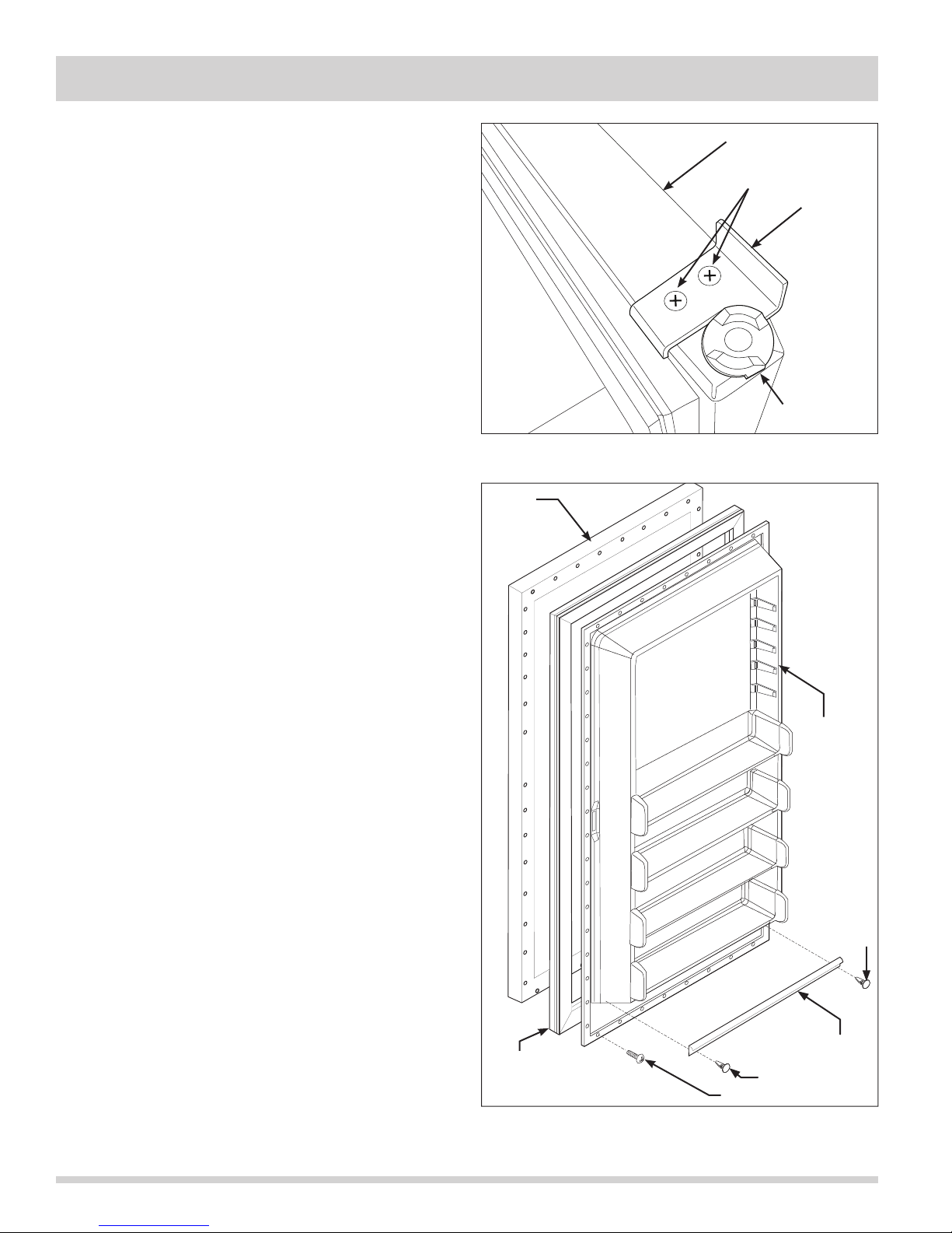
Section 5 Component Teardown
All Freezer-Pro
Door Stop Assembly Removal
The door stop is secured to with two screws the
underside of the door assembly.
To remove the door stop:
1. Remove door from unit.
2. Extract the two screws securing the door stop to the
bottom of the door assembly. (See Figure 5-34)
Door Gasket and Inner Panel Removal
The inner panel of the door assembly is secured with
screws that pass through the inner panel and fasten
into the door assembly. The door gasket has an inner
lip that is pressed between the inner panel and the door
assembly and is secured in position when the inner panel
screws are fastened to the door assembly. The inner
panel does not have to be completely removed to extract
the door gasket from the door assembly.
To remove the door gasket:
1. Lift the inside edge of the door gasket to access the
inner panel screws.
2. Loosen the inner panel screws until the door gasket
can be pulled out from under the inner panel.
(See Figure 5-35)
3. Continue loosening screws around door assembly
until door gasket is free.
4. To remove the inner panel, extract all screws from
the outside edge of the inner panel and remove from
unit.
5. The secondary gasket is secured with two retaining
clips that snap into the inner door panel. Pry out
the two retaining clips with a small putty knife, using
caution not to damage the inner door panel. The
secondary gasket is now free.
Door Frame
Screws
Door Stop
Hinge Bearing
Figure 5-34. Door Stop Removal
Outer
Door
Panel
Inner Panel
5-16
Secondary
Door
Gasket
Figure 5-35. Inner Panel and Door Gasket
Removal
Clip
Screw
Clip
Gasket
Page 61
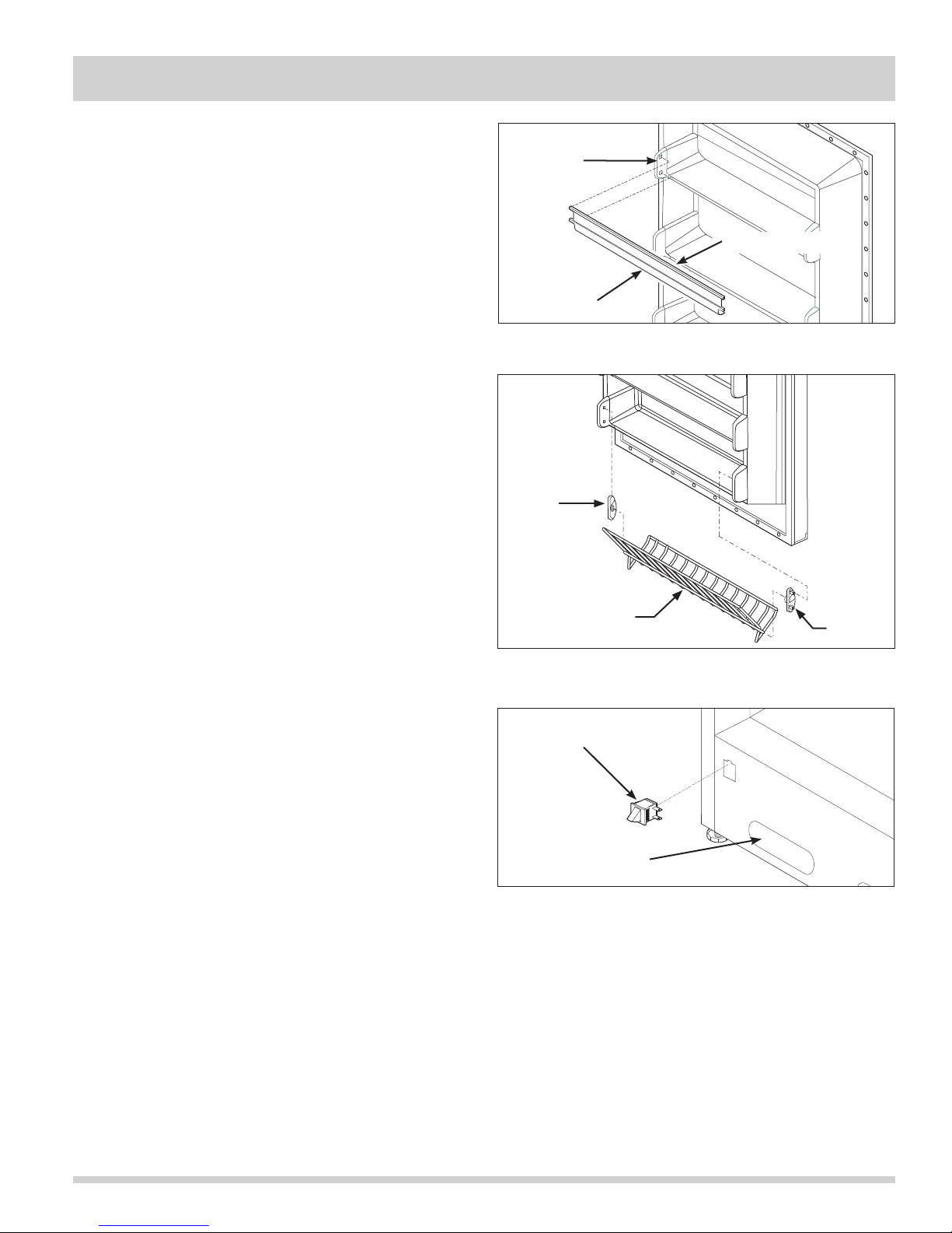
Section 5 Component Teardown
All Freezer-Pro
Door Shelf Guard Removal
The door shelf guard is secured to the inner door panel
with two tabs on each end.
To remove the door shelf guard, bend the door shelf
guard out in the middle while bending out the outer
portion of the inner panel outwards, then pull the tabs
of the door shelf guard out of the inner panel.
(See Figure 5-36)
Tilt Out Wire Shelf Removal
The tilt out wire shelves have a bar that locates in the
end caps that enable the wire shelves to tilt outward.
The end caps have two standoffs that snap into holes in
the inner panel.
To remove the tilt out wire shelves:
1. Flex the inner panel outward and lift the wire shelf
out of the end cap. Then pull the opposite end of
the wire shelf out of the opposite end cap.
(See Figure 5-37)
2. The end caps are removed by simply pulling the end
caps out of the inner panel.
Door Switch Removal
The door switch is mounted inside a hole in the cabinet
base along the lower left hand side. (See Figure 5-38)
Bend Out
Here
Door Shelf Guard
Bend Here
Figure 5-36. Door Shelf Guard Removal
End Cap
Wire Tilt-out Shelf
End Cap
Figure 5-37. Door Lock Removal
To remove the door switch:
1. Remove kickplate.
2. Reach into the access hole next to the door switch
and disconnect the electrical leads from the door
switch terminals.
3. Press in on the retaining latch on the switch body
and push switch through hole in cabinet base.
Door Switch
Access Hole
Figure 5-38. Door Switch Removal
5-17
Page 62
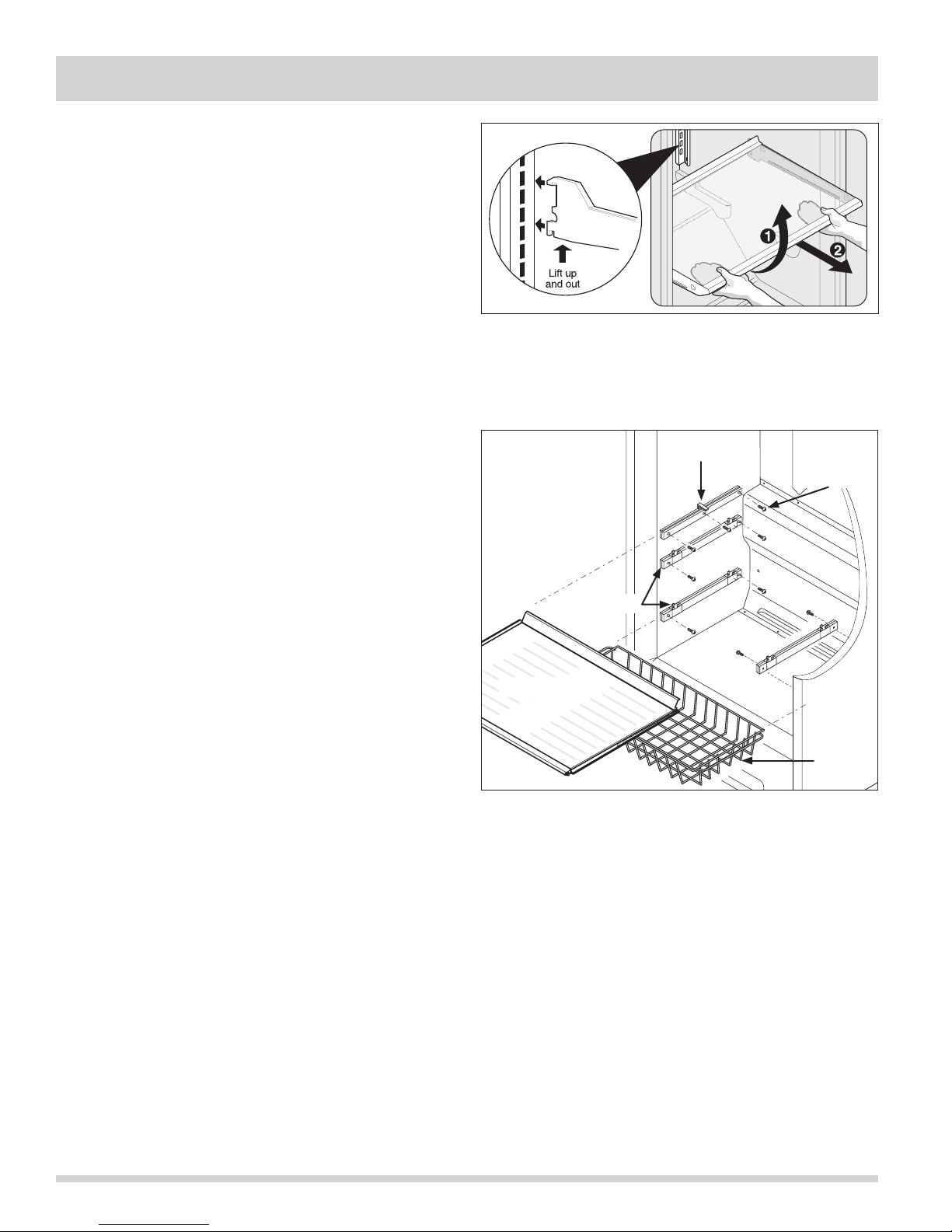
Section 5 Component Teardown
Interior Components
Adjustable Interior Shelves
Multi-position adjustable interior shelves can be moved
to any position for larger or smaller packages. The
cantilever shelves are supported at the back of the
refrigerator. (See Figure 5-39) Replace the shelf by
inserting the hooks at rear of the shelf into the wall
bracket. Lower the shelf into the desired slots and lock
into position.
To remove the shelf assemblies:
1. Lift front edge up.
2. Pull shelf out.
Glass Shelf and Glass Shelf Side Rails Removal
The glass shelf has a metal rod along each side that sets
upon the glass shelf side rails. (See Figure 5-40)
To remove the glass shelf:
1. Remove the glass shelf by pulling the glass shelf out
until it hits the stops.
2. Lift up on the front and pull the glass shelf the rest
of the way out of the cabinet interior.
All Freezer-Pro
Figure 5-39. Interior Shelving Removal
Side Rail
Screws
Basket Slides
To remove the glass shelf side rails:
1. Remove the glass shelf.
2. Extract the 3 screws securing each side rail to the
liner.
Wire Basket Removal
The wire baskets are secured with retaining clips to the
slide assemblies. (See Figure 5-40)
To remove the wire baskets:
1. Pull wire basket out from unit interior until the slides
are fully extended.
2. Pull wire basket out from the retaining clips on each
corner of the wire basket.
Wire Basket Slide Removal
The wire basket slides are secured with screws to the
liner sidewalls. (See Figure 5-40)
To remove the wire basket slides:
1. Remove wire basket from slide assembly.
2. Using a phillips head screwdriver, extract the two
screws securing the slides to the liner side wall.
Glass Shelf
Basket
Figure 5-40. Glass Shelf and Wire Basket
Assemblies Removal
5-18
Page 63
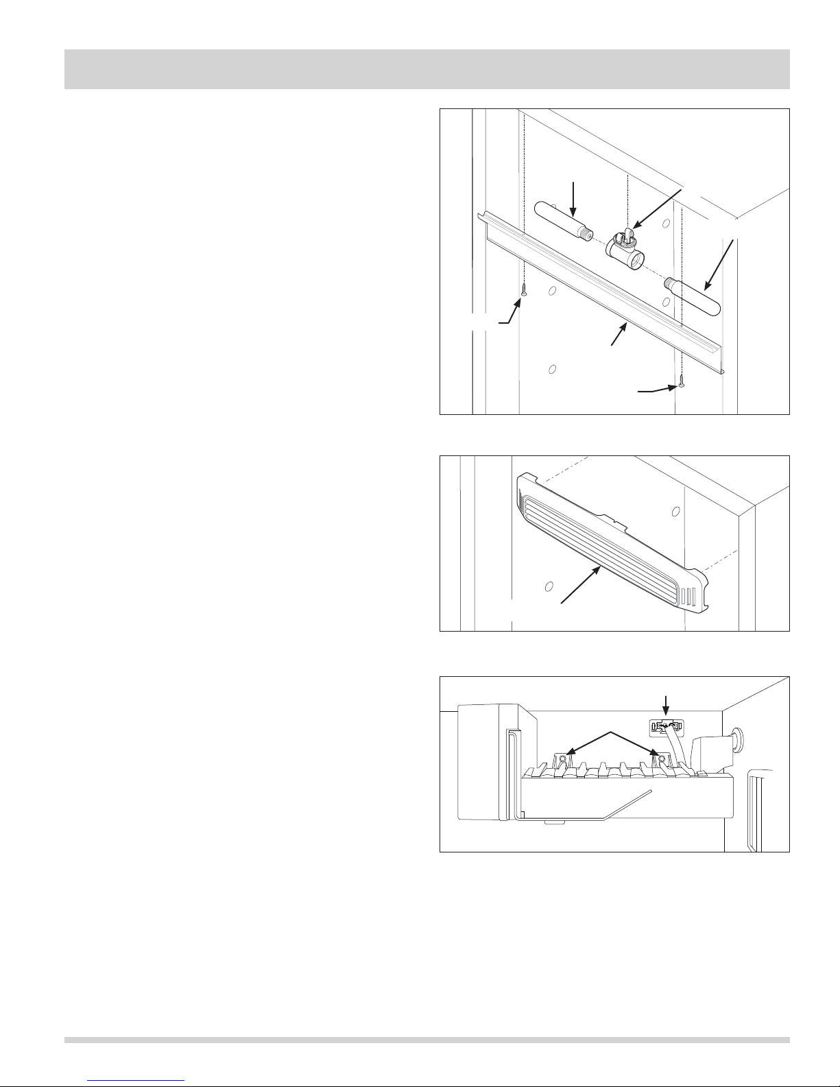
Section 5 Component Teardown
All Freezer-Pro
Light Shield Removal
To remove the light shield, extract the two screws
securing the light shield to the compartment ceiling.
Light Bulb
Light Fixture Removal
The light fixture is secured with retaining latches into the
interior cabinet ceiling behind the light shield.
(See Figure 5-41)
To remove the light fixture:
Light Fixture
Light Bulb
1. Remove light bulb by turning counter-clockwise.
2. Pull down on the front of the light fixture while
turning the fixture a quarter turn to release the
retaining latches.
3. Disconnect wire leads from light fixture terminals.
Baffle Plate Removal
To remove the baffle plate, with one hand grab the
baffle plate from the center and pull back while with
the other hand, reach behind to disengage the retaining
latches. (See Figure 5-42)
Ice Maker Removal
The icemaker is mounted with two 1/4” hex head
screws to the upper left hand corner of the freezer
compartment. (See Figure 5-43)
To remove the ice maker:
1. Remove uppermost glass shelf and ice bucket.
2. Using a 1/4” extended socket or nut driver, extract
the two screws securing the icemaker to the left
sidewall of the unit.
3. Disconnect wire leads from icemaker at the quick
disconnect mounted in the upper left corner of the
freezer compartment.
Screw
Light Shield
Screw
Figure 5-41. Light Shield and Fixture Removal
Baffle Plate
Figure 5-42. Baffle Plate Removal
Electrical Connection
Screws
Figure 5-43. Ice Maker Removal
5-19
Page 64
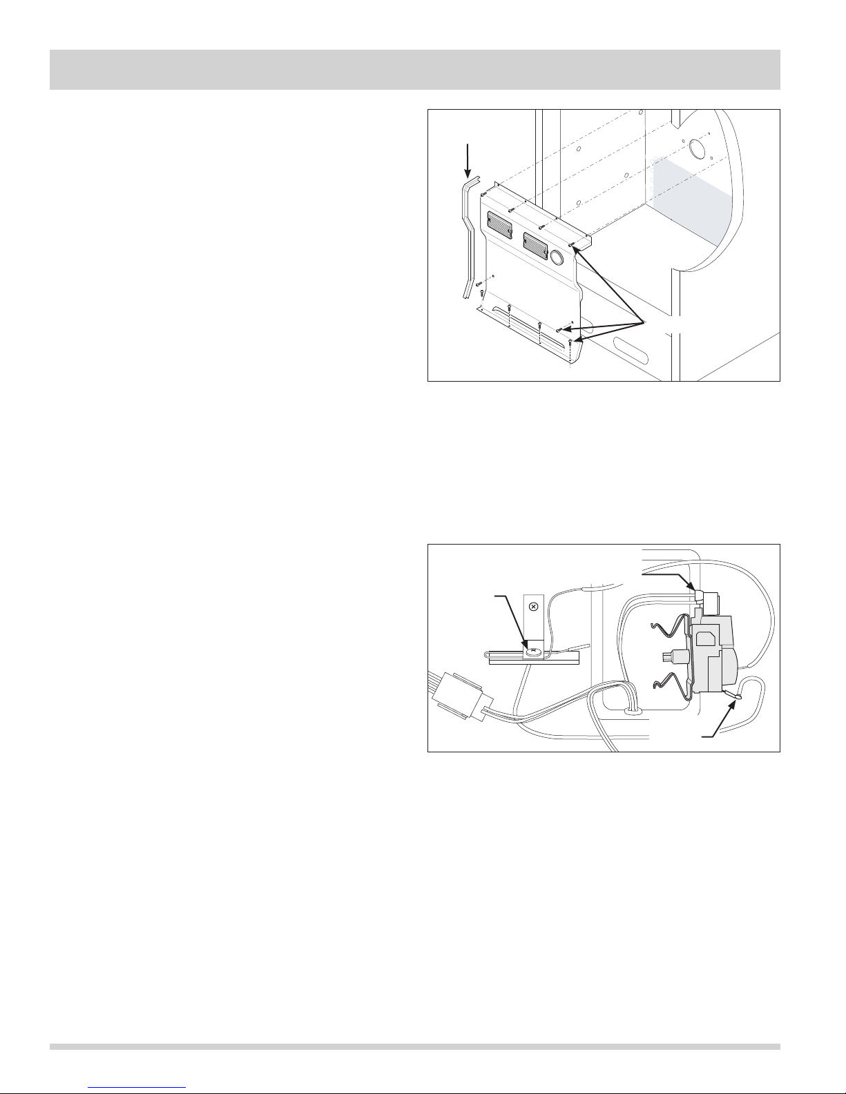
Section 5 Component Teardown
All Freezer-Pro
Evaporator Cover Removal
The evaporator cover is secured with screws to the
back wall and bottom of the freezer compartment. The
evaporator cover has a gasket on each side to create
proper airflow in the compartment. (See Figure 5-44)
To remove the evaporator cover:
1. Remove the cantilever shelves.
2. Remove the glass shelf and side rails.
3. Remove wire baskets and slides.
4. Using a phillips head screwdriver, extract the ten
(10) screws securing the evaporator cover to the
freezer compartment.
5. Pull the thermostat knob from thermostat shaft.
6. Carefully pull the evaporator cover away from the
back wall enough to access the wire harness
connections to the light fixtures and thermostat. Use
caution not to damage the gaskets on both sides of
the evaporator cover.
7. From behind the evaporator cover, disconnect the
wire leads from the light fixture terminals.
8. Compress the thermostat spring clip then pull the
thermostat from the back of the evaporator cover.
Evaporator cover may now be removed from the
unit.
Thermostat Control Removal
Gasket
1 of 2 shown
Screws
Figure 5-44. Evaporator Cover Removal
Electrical
Sensor Tube
Screw
Connection
The evaporator cover does not need to be completely
removed to access the thermostat control or the wire
harness connections, however, removing the evaporator
cover from the unit will make the task easier.
To remove the thermostat control:
1. Follow steps 1-8 above for removing the evaporator
cover.
2. Extract the screw securing the sensor tube to the
back wall of the cabinet interior. (See Figure 5-45)
3. Disconnect the 2 wire leads from the top of the
thermostat control.
4. Disconnect the ground wire lead from the thermostat
control. Thermostat control is now free.
Ground
Wire
Figure 5-45. Thermostat Control Removal
5-20
Page 65
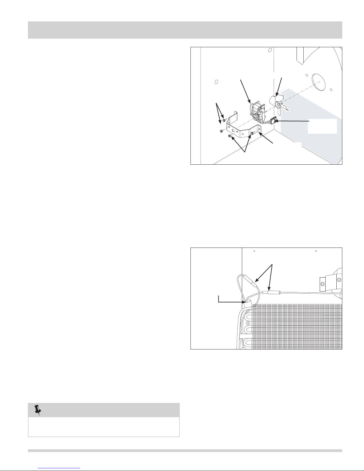
Section 5 Component Teardown
All Freezer-Pro
Evaporator Fan Assembly Removal
The evaporator fan assembly consists of the fan motor
mount bracket, fan motor and fan blade. Two screws
secure the fan motor to the fan motor mount bracket.
The evaporator fan assembly is then secured with two
screws to the back wall of the freezer compartment.
(See Figure 5-46)
To remove the evaporator fan assembly:
Fan Motor
Screws
Fan Blade
1. Remove the cantilever shelves.
2. Remove the glass shelf and side rails.
3. Remove wire baskets and slides.
4. Remove the evaporator cover.
5. Remove wires from retaining clips mounted on the
fan motor mounting bracket. Disconnect the
electrical leads of fan motor at quick disconnect.
6. Using a 5/16” socket or nut driver, extract the two
hex head screws securing the fan motor mounting
bracket to the back wall of the unit.
7. Separate the fan motor from the mounting bracket
by extracting the two hex head screws securing the
fan motor to mounting bracket.
8. Pull fan blade from fan motor shaft.
Defrost Thermostat Removal
The defrost thermostat is secured with a retaining clip to
the upper left corner of the evaporator assembly. The
defrost thermostat and wire harness connections may be
accessed without completely removing the evaporator
cover. The top of the evaporator cover may be pulled
away from the rear of the cabinet interior enough to
remove the defrost terminator and disconnect the wire
harness connections. (See Figure 5-48)
Electrical
Connection
Fan Motor
Screws
Figure 5-46. Evaporator Fan Assembly Removal
Disconnect Here
Defrost
Thermostat
Mounting
Bracket
To remove the defrost thermostat:
1. Remove the cantilever shelves.
2. Remove the glass shelf and side rails.
3. Remove wire baskets and slides.
4. Remove the evaporator cover.
5. Disconnect the defrost thermostat wire leads from
the wire harness. (See Figure 5-47)
6. Pull the defrost thermostat off of the evaporator
outlet tubing.
NOTE
Freezer defrost thermostat must be installed on
the evaporator outlet tube.
Figure 5-47. Defrost Thermostat Removal
5-21
Page 66
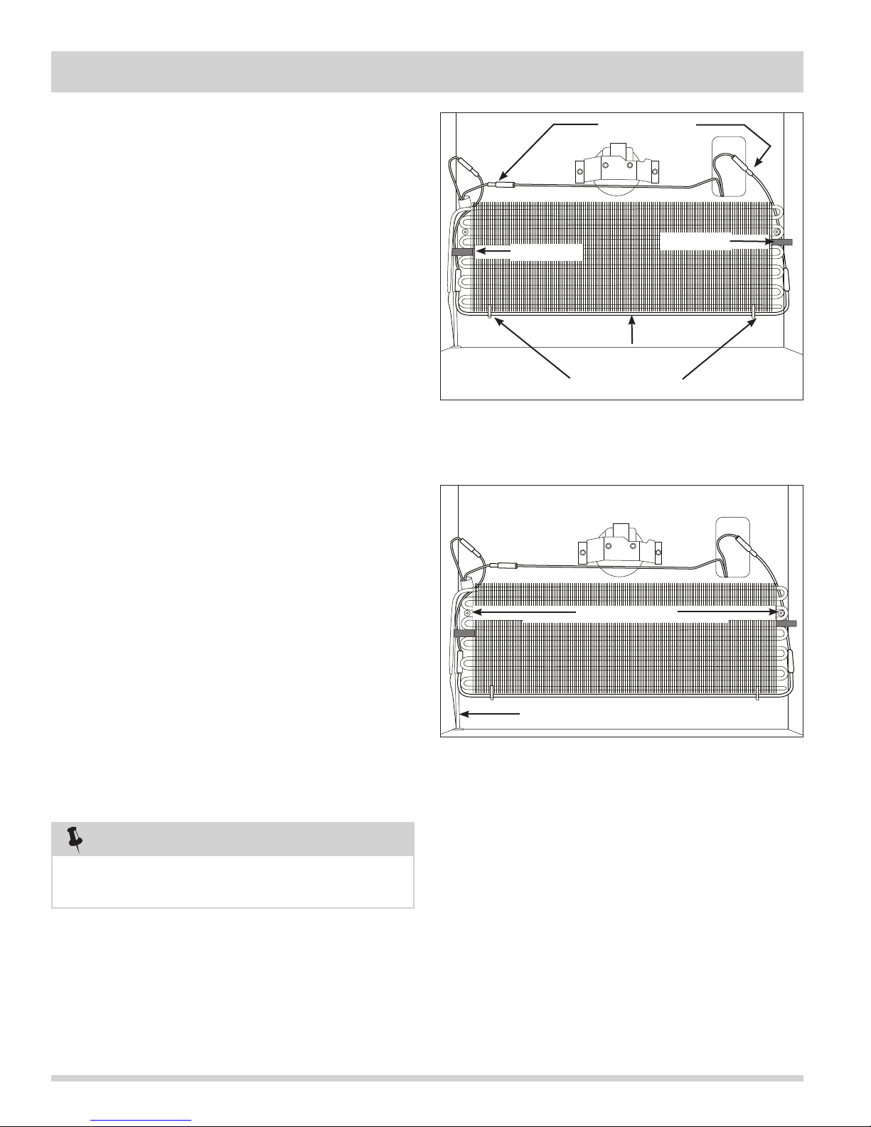
Section 5 Component Teardown
All Freezer-Pro
Defrost Heater Removal
The defrost heater is secured with two aluminum straps
to the bottom tube of the evaporator assembly.
(See Figure 5-48)
To remove the defrost heater:
1. Remove the cantilever shelves.
2. Remove the glass shelf and side rails.
3. Remove wire baskets and slides.
4. Remove the evaporator cover.
5. Disconnect the defrost heater wire leads from the
wire harness. (See Figure 5-48)
6. Release the aluminum straps securing the defrost
heater to the bottom of the evaporator assembly.
7. Remove the styrofoam insulators from both sides of
the evaporator.
8. Pull defrost heater from evaporator assembly.
Evaporator Removal
The evaporator sets upon the two screw standoffs
mounted to the back wall of the freezer compartment.
Two pieces of styrofoam are pressed between the
evaporator assembly and the sidewalls of the unit,
securing the assembly in position. (See Figure 5-49)
To remove the evaporator:
Disconnect Here
Styrofoam
Defrost Heater
Aluminum Straps
Figure 5-48. Defrost Heater Removal
Screw Standoffs
Styrofoam
1. Remove the cantilever shelves.
2. Remove the glass shelf and side rails.
3. Remove wire baskets and slides.
4. Remove the evaporator cover.
5. Remove the styrofoam insulators from both sides of
the evaporator.
6. Remove the defrost thermostat and defrost heater.
7. Recover refrigerant by using EPA approved
recovery system.
NOTE
Whenever the sealed system is opened the
filter-drier must be replaced.
8. Remove the filter-drier.
9. Cut suction line about 1” from compressor.
10. Straighten the tubing, remove the foam sleeve, and
carefully feed the heat exchanger through the
cabinet while pulling up on the evaporator.
Heat Exchanger
Figure 5-49. Evaporator Removal
5-22
Page 67
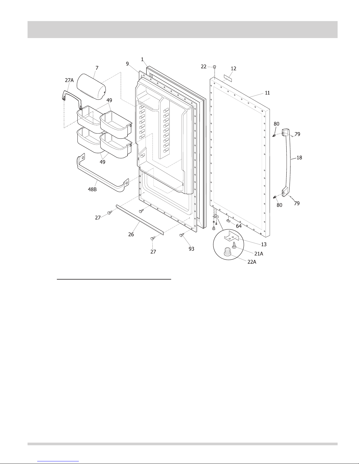
Section 6 Parts List
All Refrigerator Door Exploded View And Parts List
Ref # Part # Description
1 216522311 Gasket-door, black
7 240338313 Door, dairy, clear
9 216953600 Panel-inner door, refr
11 297316517 Panel-outer door, stainless
12 242015101 Label-nameplate
13 297257000 Door Stop, chrome, RH
18 241972501 Handle-door, stainless
* 240537301 Nut-anchor, door hdl screw
* 297048000 Screw, anchor, #8, white
21A 297197500 Screw, door stop mtg, FH38-16X.750, P Twin
22 216970800 Bearing, hinge w/o’ring, top
22A 297006800 Bearing-hinge, btm, w/o’ring
26 216524201 Gasket, secondary
27 5304472186 Clip, panel mtg
27* 5304406520 Clip, panel mtg kit, (40)
27A 240396102 Retainer, tall bottle
48B 240338001 Bin-door, pseudo, gallon, refr
49 216959802 Bin-door, 2-liter, (4)
64 216403700 Plug-button, hole filler, door base
79 218755401 Screw-set, 10-32 x 0.375
80 218755504 Screw-shoulder, #10 AB, handle mounting
93 5304460605 Screw, ph truss head, 8-18AB x 0.500
# Functional Parts
* Non-Illustrated Parts
6-1
Page 68
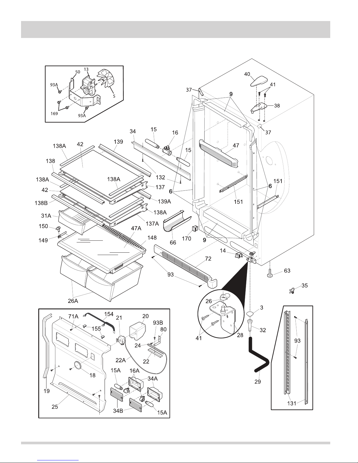
Section 6 Parts List
All Refrigerator Cabinet Exploded View And Parts List
6-2
Page 69

Section 6 Parts List
Ref # Part # Description Ref # Part # Description
3 216503100 Screen-drain
5 297259600 Fan Blade, evaporator
6 297200600 Breaker Kit w/corners, no lock
slot
9 297200100 Breaker Kit w/corners, 32”, top
and bottom
13 # 297250000 Motor, fan, 115 V
14 216922800 Switch, light/lamp, ramp
15 216988100 Light Bulb/Lamp, long, blue
tint, 40 W, 120V
15A 297048600 Light Bulb/Lamp, short
16 241507803 Socket-light
16* 297109500 Washer, vinyl
16A 297139501 Socket, light/lamp, 25 W
18 216707200 Knob, temp control
19 216204902 Gasket-evap cover
20 216967200 Cover, temp control
21 # 216715500 Control temperature
22 216823500 Clamp, cap tube, cold control
22A 297058500 Tube, 10”, plastic
24 5304460604 Screw, type A, 10-24 x 3/8
25 297099253 Cover-evaporator
26 216503300 Ramp, door closer
26A 216959900 Pan-crisper, (2)
28 297283900 Hinge-bottom, stepped pin
29 216313501 Hose-drain
31A 240530811 Pan-meat, w/o graphics, clear
32 5308005500 Drain
34 216816225 Shield-light
34A 297053102 Shield-light
34B 297053200 Lens, light
35 216273000 Clip, drain hose
37 297273901 Trim-cabinet corner, black, (2)
38 297283800 Hinge-upper
40 297164401 Cover-upper hinge, black
41 240578902 Screw, hex head, 1/4-20 x 5/8
42 216983102 Glass-shelf
47 297192900 Baffle, air
47A 240350608 Insert-pan cover, 23.82” x
15.50”, glass
50 08013207 Bracket-fan motor
63 216396900 Screw, leveling foot, plastic,
adjustable
63* 297164650 Bracket, LH leg levelor
63* 297164651 Bracket, RH leg levelor
66 5303295947 Rack-wine
71A 297146800 Screw, 8-18AB x 0.470
72 297036901 Grille/Kickplate, 32”, black
80 06594601 Bracket, control
93 5304460605 Screw, ph truss head, 8-18AB x
0.500
93A 297174300 Screw, #8, 18x.63, self pierce
* 216327800 Clip, wire
93B 216036601 Screw, RWHD, 8-32A x 0.500,
GX-CA
131 241513001 Channel-shelf mtg, side, (2)
132 5304460601 Screw, 6-20AB x 3/8
137 297050600 Frame-shelf, cantilever, (2)
137A 297050601 Frame-shelf, cantilever
138 297050700 Trim-shelf, front, (2)
138A 216983601 Trim-shelf, side
138B 297050701 Trim-shelf, front
139 297050800 Trim-shelf, rear, (2)
139A 297050801 Trim-shelf, rear
148 216979403 Cover-crisper pan
149 240361301 Damper, humidity cont.
150 240361202 Knob, humidity cont.
151 216988200 Support-crspr cover, RH
151 216988201 Support-crspr cover, LH
154 297053000 Wire, jumper
155 5303313703 Clip, (2)
169 216912401 Screw, hex washer head, 8-32
x 0.500, bracket fan mtr, (2)
170 297280401 Valve, breather, black
* 297001704 Insulation, 24”, drain tube
* 297226507 Energy Guide
# Functional Parts
* Non-Illustrated Parts
6-3
Page 70
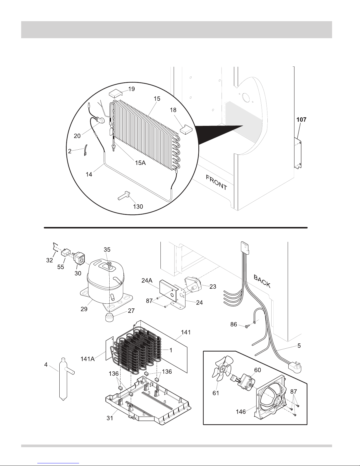
Section 6 Parts List
All Refrigerator Sealed System Exploded View And Parts List
6-4
Page 71

Section 6 Parts List
Ref # Part # Description
1 # 297152200 Condenser, dynamic
2 5308000110 Strap-evap/heater, aluminum, (2)
4 # 216938600 Drier-filter
5 # 297171800 Harness-main
5* 240555002 Screw-#8-32 X 3/8
14 297216101 Heater-defrost
15 # 216997300 Evaporator
15A 297319400 Heat Exchanger
18 297078701 Insulator-evap, styrofoam, RH
19 297078801 Insulator-evap, styrofoam, LH
20 216731001 Thermostat, defrost
23 # 216744500 Timer-defrost
24 216968501 Bracket-timer
24A 297207900 Guard, timer
27 297293300 Grommet, compressor
29 # 297270400 Compressor, w/o electricals
30 216954229 Controller, compressor
31 297165800 Pan-drain
32 216649200 Clip, controller
35 297177200 Bolt, compressor
55 # 218909912 Capacitor, run, 220 VAC, 12 microfarad
60 241584301 Motor-condenser fan
61 241639501 Blade-condenser fan
86 216036601 Screw, RWHD, 8-32A x 0.500, GX-CA
87 5304463290 Screw, hi-lo blunt, #8-18X1/2
107 297165400 Shield, compressor, Compartment
* 5304460605 Screw, ph truss head, 8-18AB x 0.500
130 297244700 Support, evaporator mtg
136 240405201 Grommet, rubber, black, cond tube/wire
141 297164200 Divider, air flow
141A 297194700 Divider, small, air flow
146 297164000 Shroud-fan orfice
146* 216337701 Screw, HWH, 10-24 x 0.500, Swage
* 216502500 Sleeve, suction line
* 297174300 Screw, #8, 18x.63, self pierce
* # 297169901 Cord-power, flat
* 297315800 Clip, wire
# Functional Parts
* Non-Illustrated Parts
6-5
Page 72
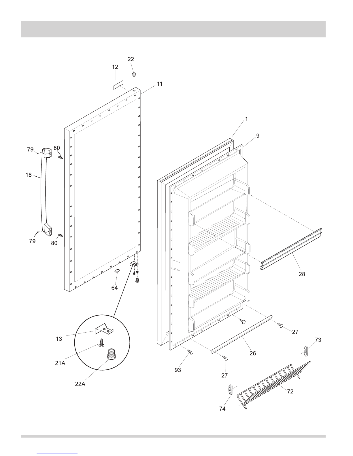
Section 6 Parts List
All Freezer Door Exploded View And Parts List
6-6
Page 73

Section 6 Parts List
Ref # Part # Description
1 216522311 Gasket-door, black
9 216527813 Panel-inner door
11 297316518 Panel-outer door, stainless
12 242015101 Label-nameplate
13 297257002 Door Stop, LH
18 241972501 Handle-door, stainless
* 240537301 Nut-anchor, door hdl screw
* 297048000 Screw, anchor, #8, white
21A 5304460608 Screw, flat head, #1/4-20, door stop/hng
22 216970800 Bearing, hinge w/o’ring, top
22A 297006800 Bearing-hinge, btm, w/o’ring
26 216524201 Gasket, secondary
27 5304472186 Clip, panel mtg
27* 5304406520 Clip, panel mtg kit, (40)
28 216806100 Rack-door, contour, (3)
64 216403700 Plug-button, hole filler, door base
72 297118100 Shelf, tilt out, wire
73 216513900 End Cap, shelf, LH, tilt-out
74 216514000 End Cap, shelf, RH, tilt-out
79 218755401 Screw-set, 10-32 x 0.375
80 218755504 Screw-shoulder, #10 AB, handle mounting
93 5304460605 Screw, ph truss head, 8-18AB x 0.500
# Functional Parts
* Non-Illustrated Parts
6-7
Page 74
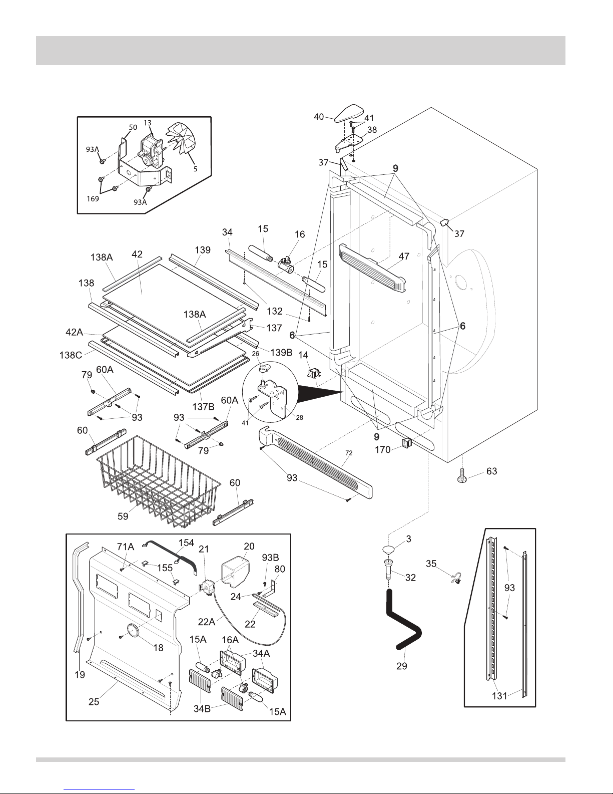
Section 6 Parts List
All Freezer Cabinet Exploded View And Parts List
6-8
Page 75

Section 6 Parts List
Ref # Part # Description Ref # Part # Description
3 216503100 Screen-drain
5 297259600 Fan Blade, evaporator
6 297200600 Breaker Kit w/corners, no lock
slot
9 297200100 Breaker Kit w/corners, 32”, top
and bottom
13 # 297250000 Motor, fan, 115 V
14 216998100 Switch, light/lamp, black, ramp
15 216988100 Light Bulb/Lamp, long, blue
tint, 40 W, 120V
15A 297048600 Light Bulb/Lamp, short
16 241507803 Socket-light
16* 297109500 Washer, vinyl
16A 297139501 Socket, light/lamp, 25 W
18 216707200 Knob, temp control
19 216204902 Gasket-evap cover
20 216967200 Cover, temp control
21 216715200 Control-temperature
22 216823500 Clamp, cap tube, cold control
22A 5303916855 Tube, sensor sleeve, plastic,
clear
24 5304460604 Screw, type A, 10-24 x 3/8
25 297099253 Cover-evaporator
26 297248200 Ramp, door closer, LH
28 297283901 Hinge-bottom, stepped pin, LH
29 216313501 Hose-drain
32 5308005500 Drain
34 216816225 Shield-light
34A 297053102 Shield-light
34B 297053200 Lens, light
35 216273000 Clip, drain hose
37 241611303 Trim-cabinet corner, black, (2)
38 297283800 Hinge-upper
40 297164401 Cover-upper hinge, black
41 240578902 Screw, hex head, 1/4-20 x 5/8
42 216983102 Glass-shelf
42A 297007702 Glass-shelf, sliding
47 297192900 Baffle, air
50 08013207 Bracket-fan motor
59 297119000 Basket, (2)
60 297054200 Slide-basket, RH, (2), w/clips
60 297054201 Slide-basket, LH, (2), w/clips
60* 297049500 Clip-slide, basket
60A 297013500 Slide, basket
63 216396900 Screw, leveling foot, plastic,
adjustable
71A 297146800 Screw, 8-18AB x 0.470
72 297036901 Grille/Kickplate, 32”, black
79 3017666 Nut-insert
80 06594601 Bracket, control
93 5304460605 Screw, ph truss head, 8-18AB x
0.500
93A 297174300 Screw, #8, 18x.63, self pierce
* 216327800 Clip, wire
93B 216036601 Screw, RWHD, 8-32A x 0.500,
GX-CA
131 241513001 Channel-shelf mtg, side, (2)
132 5304460601 Screw, 6-20AB x 3/8
137 297050600 Frame-shelf, cantilever
137B 297007600 Frame-shelf, sliding
138 297050700 Trim-shelf, front
138A 216983601 Trim-shelf, side
138C 297007800 Trim-shelf, front
139 297050800 Trim-shelf, rear
139B 297007900 Trim-shelf, rear
154 297053000 Wire, jumper
155 5303313703 Clip, (2)
169 216912401 Screw, hex washer head, 8-32
x 0.500, bracket fan mtr, (2)
170 297280401 Valve, breather, black
* 216893800 Cover, external, ice maker, (2)
* 216910416 Energy Guide
* 241586701 Plug-foam-wtr-inlet, round
* 297001704 Insulation, 24”, drain tube
* 297013100 Instructions, water line
* 297095300 Plug, white
* 216901700 Installation Instructions, ice
maker
* IM501 Ice Maker Kit
# Functional Parts
* Non-Illustrated Parts
6-9
Page 76
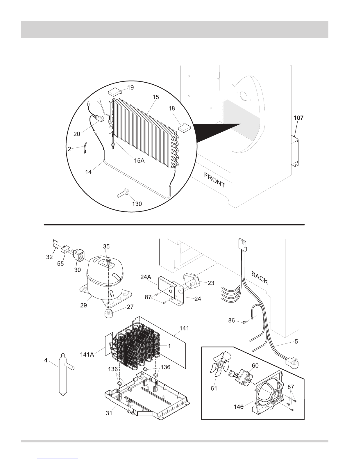
Section 6 Parts List
All Freezer Sealed System Exploded View And Parts List
6-10
Page 77

Section 6 Parts List
Ref # Part # Description
1 297152201 Condenser
2 5308000110 Strap-evap/heater, aluminum, (2)
4 216987500 Drier-filter
5 # 297315700 Harness-main
14 297216101 Heater-defrost
15 # 216997300 Evaporator
15A 297238700 Heat Exchanger
18 297078701 Insulator-evap, styrofoam, RH
19 297078801 Insulator-evap, styrofoam, LH
20 297216600 Thermostat, defrost
23 # 216744500 Timer-defrost
24 216968501 Bracket-timer
24A 297207900 Guard, timer
27 5308002681 Grommet, compressor
29 # 297237400 Compressor, w/o electricals
30 216954212 Controller, compressor
31 297165800 Pan-drain
32 216649200 Clip, controller
35 297177200 Bolt, compressor
55 # 218909912 Capacitor, run, 220 VAC, 12 microfarad
60 241584301 Motor-condenser fan
61 241639501 Blade-condenser fan
86 216036601 Screw, RWHD, 8-32A x 0.500, GX-CA
87 5304463290 Screw, hi-lo blunt, #8-18X1/2
107 297165400 Shield, compressor, Compartment
* 5304460605 Screw, ph truss head, 8-18AB x 0.500
130 297244700 Support, evaporator mtg
136 240405201 Grommet, rubber, black, cond tube/wire
141 297164200 Divider, air flow
141A 297194700 Divider, small, air flow
146 297164000 Shroud-fan orfice
146* 216337701 Screw, HWH, 10-24 x 0.500, Swage
* 216502500 Sleeve, suction line
* 240555002 Screw-#8-32 X 3/8
* 297014500 Plug-suction line
* 297048400 Clip
* 297174300 Screw, #8, 18x.63, self pierce
* # 297169900 Cord-power, flat
# Functional Parts
* Non-Illustrated Parts
6-11
Page 78
Section 6 Parts List
Notes
6-12
Page 79
Section 7 Troubleshooting
Problem
Freezer/refrigerator
compressor does not run.
Freezer/refrigerator runs
too much or too long.
Cause
Unit is plugged into a circuit that has a
ground fault interrupt.
Temperature control is in the “OFF”
position.
Unit may not be plugged in, or plug may
be loose.
House fuse blown or tripped
circuit breaker.
Power outage.
Room or outside weather is hot.
Unit has recently been disconnected for a
period of time.
Large amount of warm or hot food have
been stored recently.
Door is opened too frequently or kept
open too long.
Correction
Use another circuit. Check circuit for proper
voltage.
Set control to a temperature setting. Instruct
customer.
Ensure plug is tightly pushed into outlet.
Check/replace fuse with a 15 amp time delay fuse.
Reset circuit breaker.
Check house lights. Call local Electric Company.
It’s normal for the freezer/refrigerator to work
harder under these conditions.
It takes 4 hours for the unit to cool down
completely.
Warm food will cause unit to run more until the
desired temperature is reached.
Warm air entering the unit causes it to run more.
Open the door less often.
Interior freezer/refrigerator
temperature is too cold.
Interior freezer/refrigerator
temperature is too warm.
Unit door may be slightly open.
Temperature control is set too
low.
Freezer/refrigerator gaskets are dirty,
worn, cracked or poorly fitted.
Temperature control is set too low.
Temperature control is set too warm.
Door is opened too frequently or kept
open too long.
Unit door may be slightly open.
Large amount of warm or hot food have
been stored recently.
Unit has recently been disconnected for a
period of time.
See Problem section “Door will not close”.
Set control to a warmer setting. Allow
several hours for the temperature to stabilize.
Clean or change gasket. Leaks in the door seal
will cause unit to run longer in order to maintain
desired temperature.
Set control to a warmer setting. Allow
several hours for the temperature to stabilize.
Set control to a colder setting. Allow
several hours for the temperature to stabilize.
Warm air entering the unit causes it to run more.
Open the door less often.
See Problem section “Door will not close”.
Wait until the unit has had a chance to reach its
selected temperature.
Unit requires 24 hours to cool down
completely.
Freezer/refrigerator
external surface
temperature is warm.
The external freezer/refrigerator walls
can be as much as 30ºF warmer than
room temperature.
This is normal while the compressor works to
transfer heat from inside the unit cabinet.
7-1
Page 80
Section 7 Troubleshooting
Problem CorrectionCause
Louder sound levels
whenever Freezer/
refrigerator is on.
Louder sound levels when
compressor comes on.
Popping or cracking sound
when compressor comes
on.
Bubbling or gurgling
sound.
Vibrating or rattling noise.
Moisture forms on inside
Freezer/refrigerator walls.
Modern Freezers have increased storage
capacity and more stable temperatures.
They require heavy duty compressors.
Freezer/refrigerator operates at higher
pressures during the start of the ON cycle.
Metal parts undergo expansion and
contraction, as in hot water pipes.
Refrigerant used to cool the unit is
circulating throughout system.
Freezer/refrigerator is not level. It rocks on
the floor when it is moved slightly.
Floor is uneven or weak.
Freezer/refrigerator is touching the wall.
Weather is hot and humid, which
increases internal rate of frost build-up.
Door is slightly open.
This is normal. When the surrounding noise level is
low, you might hear the compressor running while it
cools the interior.
This is normal. Sound will level off or disappear as
freezer/refrigerator continues to run.
This is normal. Sound will level off or disappear as
freezer/refrigerator continues to run.
This is normal.
Level the freezer/refrigerator.
Ensure floor can adequately support unit. Level the
unit by putting wood or metal shims under part of
the unit
Re-level freezer/refrigerator or move slightly.
This is normal.
See Problem section “Door will not close”.
Odors in Freezer/
refrigerator.
Door will not close.
Light bulb is not on.
Automatic ice maker not
working. (Some freezer
models)
Door is opened too frequently or kept open
too long.
Interior needs to be cleaned.
Foods with strong odors are in the Freezer.
Freezer/refrigerator is not level. It rocks on
the floor when it is moved slightly.
Floor is uneven or weak.
The fluorescent lamp or light bulb is
burned out.
No electric current is reaching the freezer/
refrigerator.
Ice maker is not working
Open the door less often.
Clean interior with sponge, warm water, and
baking soda. Replace air filter.
Cover the food tightly.
This condition can force the cabinet out of square
and misalign the door. Level unit.
Ensure floor can adequately support unit. Level the
unit by putting wood or metal shims under part of
the unit.
Replace lamp or light bulb.
See Problem section “Freezer/refrigerator
compressor does not run” on previous page.
1. Ensure the wire signal arm is not in the UP
position.
2. Water supply is turned off.
3. Water pressure is too low.
4. The freezer is not cold enough.
7-2
Page 81
Section 7 Troubleshooting
The following table relates to troubleshooting the thermostat, electronic components and compressor with its
associated components.
Problem
Compressor and evaporator
fan motor does not run.
Compressor does not run,
but the evaporator fan
motor does.
Evaporator fan motor does
not run,but the compressor
operates.
Interior light does not glow
when door is opened.
Compressor runs
continuously, but freezer is
not cold.
Compressor runs
continuously and the
freezer/refrigerator is too
cold.
Freezer/refrigerator does
not automatically defrost.
Cause
1. Is the temperature control set to off?
2. Measure the input voltage to the
electronic control. Is line to neutral
voltage being applied?
3. Disconnect the wiring harness
from the compressor controller and
measure the voltage drop between
the two wires in the harness. Does
the meter read line to neutral
voltage?
1. Defective compressor or compressor
controller.
1. Is there something blocking the fan
blade?
1. Check the light bulb with an
ohmmeter. Is the bulb good?
1. Connect a low side gauge to the
processing tube on the compressor.
Is the pressure in a vacuum or lower
than normal?
1. Defective thermostat.
1. Defective timer.
Correction
Yes. Set control from 1 to 7
No. Go to step 3.
Yes. Replace defective electronic control.
No. Defective wire harness.
Yes. Replace defective compressor controller or
compressor and evaporator fan motor.
No. Replace defective electronic control.
Replace compressor controller. If problem is not
corrected replace compressor.
Yes. Remove restriction from fan blade.
No. Replace defective fan motor.
Yes. Replace defective door switch.
No. Replace light bulb.
Yes. System low on refrigerant, check for leak in
system before adding refrigerant.
No. Replace defective compressor.
Replace defective thermostat.
Yes. Check/replace defrost thermostat.
Yes. Check/replace defrost heater.
No. Replace defrost timer.
7-3
Page 82
Section 7 Troubleshooting
Notes
7-4
Page 83
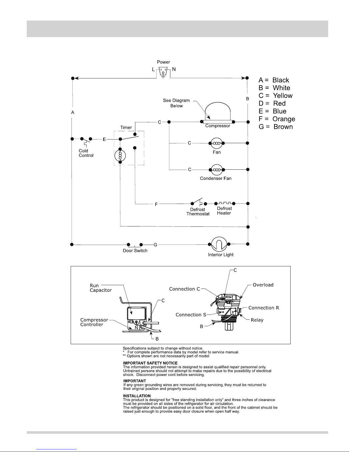
Section 8 Wiring Diagram
All Refrigerator Wiring Diagram
8-1
Page 84
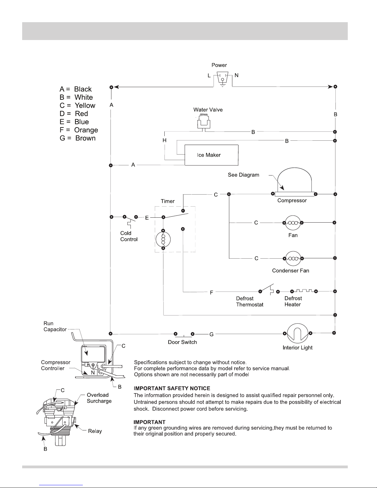
Section 8 Wiring Diagram
All Freezer Wiring Diagram
8-2
 Loading...