

Electrolux EW3LDF65GBA, EW3LDF65GSA, EW3LDF65GSB, EW3LDF65GSE, EW3LDF65GSG Installation Guide
...Page 1
iNSTALLATiON AND SERVICE MUST BE
PERFORMED BY A QUALIFIED iNSTALLER.
iMPORTANT: SAVE FOR LOCAL ELECTRICAL
iNSPECTOR'S USE.
READ AND SAVE THESE iNSTRUCTiONS FOR
FUTURE REFERENCE.
Refer to your serial plate for applicable
agency certifications
Provide Proper Fuel Type
Before Proceeding: You r range is preset to operate on h P.
(Liquified Petroleum) Gas only.
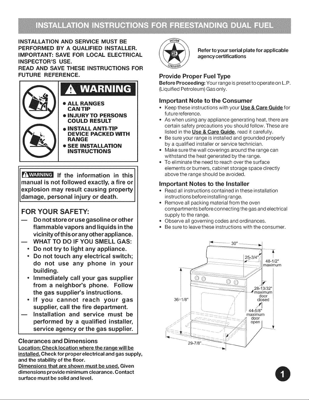
• ALL RANGES
CAN TiP
• INJURYTO PERSONS
COULD RESULT
• iNSTALL ANTi=TIP
DEVICE PACKED WiTH
RANGE
• SEE iNSTALLATiON
iNSTRUCTiONS
I_ if the information in this j
manual is not followed exactly, a fire or I
explosion may result causing property I
damage, personal injury or death, j
FOR YOUR SAFETY:
m Do not store or use gasoline or other
flammable vapors and liquids in the
vicinity of this or any other appliance.
= WHAT TO DO iF YOU SMELL GAS:
• Do not try to light any appliance.
• Do not touch any electrical switch;
do not use any phone in your
building.
• Immediately call your gas supplier
from a neighbor's phone. Follow
the gas supplier's instructions.
• if you cannot reach your gas
supplier, call the fire department.
= Installation and service must be
performed by a qualified installer,
service agency or the gas supplier.
important Note to the Consumer
= Keep these instructions with your Use & Care Guide for
future reference.
= As when using any appliance generating heat, there are
certain safety precautions you should follow. These are
listed in the Use & Care Guide, read it carefully.
• Be sure your range is installed and grounded properly
by a qualified installer or service technician.
Make sure the wall coverings around the range can
withstand the heat generated by the range.
To eliminate the need to reach over the surface
elements or burners, cabinet storage space directly
above the range should be avoided.
important Notes to the installer
= Read all instructions contained inthese installation
instructions before installing range.
Remove all packing material from the oven
compartments before connecting the gas and electrical
supply to the range.
Observe all governing codes and ordinances.
Be sure to leave these instructions with the consumer.
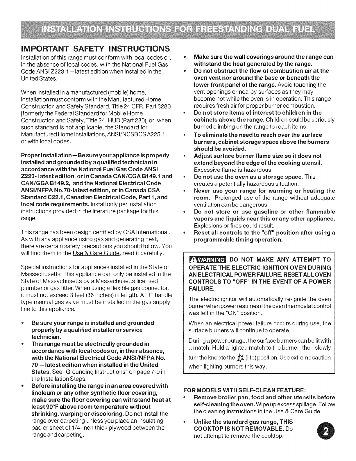
48-1/2"
maximum
f .....
36+1/8 ''
\ door
closed
maximum
door
Clearances and Dimensions
Location: Check location where the range will be
installed. Check for proper electrical and gas supply,
and the stability of the floor.
Dimensions that are shown must be used. Given
dimensions provide minimum clearance. Contact
surface must be solid and level.
Page 2
iMPORTANT SAFETY iNSTRUCTiONS
Installation of this range must conform with local codes or,
in the absence of local codes, with the National Fuel Gas
Code ANSI Z223.1 --latest edition when installed in the
United States.
When installed ina manufactured (mobile) home,
installation must conform with the Manufactured Home
Construction and Safety Standard, Title 24 CFR, Part 3280
[formerly the Federal Standard for Mobile Home
Construction and Safety, Title 24, HUD (Part 280)] or, when
such standard is not applicable, the Standard for
Manufactured Home Installations, ANSI/NCSBCS A225.1,
or with local codes.
Proper Installation = Be sure your appliance is properly
installed and grounded by a qualified technician in
accordance with the National Fuel Gas Code ANSI
Z223= latest edition, or in Canada CAN/CGA B149.1 and
CAN/GGA B149.2, and the National Electrical Code
ANSI/NFPA No.70=latest edition, or in Canada CSA
Standard 022.1, Canadian Electrical Code, Part 1, and
local code requirements. Install only per installation
instructions provided in the literature package for this
range.
This range has been design certified by CSA International.
As with any appliance using gas and generating heat,
there are certain safety precautions you should follow. You
will find them in the Use & Care Guide, read it carefully.
Special instructionsfor appliances installed inthe State of
Massachusetts: This appliance can only be installed in the
State of Massachusetts by a Massachusetts licensed
plumber or gas fitter. When using a flexible gas connector,
it must not exceed 3 feet (36 inches) in length. A "T" handle
type manual gas valve must be installed in the gas supply
line to this appliance.
= Be sure your range is installed and grounded
properly by a qualified installer or service
technician.
= This range must be electrically grounded in
accordance with local codes or, intheir absence,
with the National Electrical Code ANSVNFPA No.
70 = latest edition when installed in the United
States. See "Grounding Instructions" on page 7-9 in
the Installation Steps.
= Before installing the range in an area covered with
linoleum or any other synthetic floor covering,
make sure the floor covering can withstand heat at
least 90°F above room temperature without
shrinking, warping or discoloring. Do not installthe
range over carpeting unless you place an insulating
pad or sheet of 1/4-inch thick plywood between the
range and carpeting.
= Make sure the wall coverings around the range can
withstand the heat generated by the range.
= Do not obstruct the flow of combustion air at the
oven vent nor around the base or beneath the
lower front panel of the range. Avoid touching the
vent openings or nearby surfaces as they may
become hot while the oven is in operation. This range
requires fresh air for proper burner combustion.
Do not store items of interest to children in the
cabinets above the range. Children could be seriously
burned climbing on the range to reach items.
. To eliminate the need to reach over the surface
burners, cabinet storage space above the burners
should be avoided.
= Adjust surface burner flame size so it does not
extend beyond the edge of the cooking utensil.
Excessive flame is hazardous.
= Do not use the oven as a storage space. This
creates a potentially hazardous situation.
= Never use your range for warming or heating the
room. Prolonged use of the range without adequate
ventilation can be dangerous.
= Do not store or use gasoline or other flammable
vapors and liquids near this or any other appliance.
Explosions or fires could result.
Reset all controls to the "off" position after using a
programmable timing operation.
DO NOT MAKE ANY ATTEMPT TO
OPERATE THE ELECTRIC IGNITION OVEN DURING
AN ELECTRICAL POWER FAILURE. RESETALL OVEN
CONTROLS TO "OFF" IN THE EVENT OF A POWER
FAILURE.
The electric ignitor will automatically re-ignite the oven
burner when power resumes ifthe oven thermostat control
was left in the "ON" position.
When an electrical power failure occurs during use, the
surface burners will continue to operate.
During a power outage, the surface burners can be lit with
a match. Hold a lighted match to the burner, then slowly
turn the knobtothe _ (lite) position. Use extreme caution
when lighting burners this way.
FOR MODELS WITH SELF=CLEAN FEATURE:
• Remove broiler pan, food and other utensils before
self-cleaning the oven. Wipe up excess spillage. Follow
the cleaning instructions in the Use & Care Guide.
= Unlike the standard gas range, THIS
COOKTOP IS NOT REMOVABLE. Do
not attempt to remove the cooktop.
Page 3
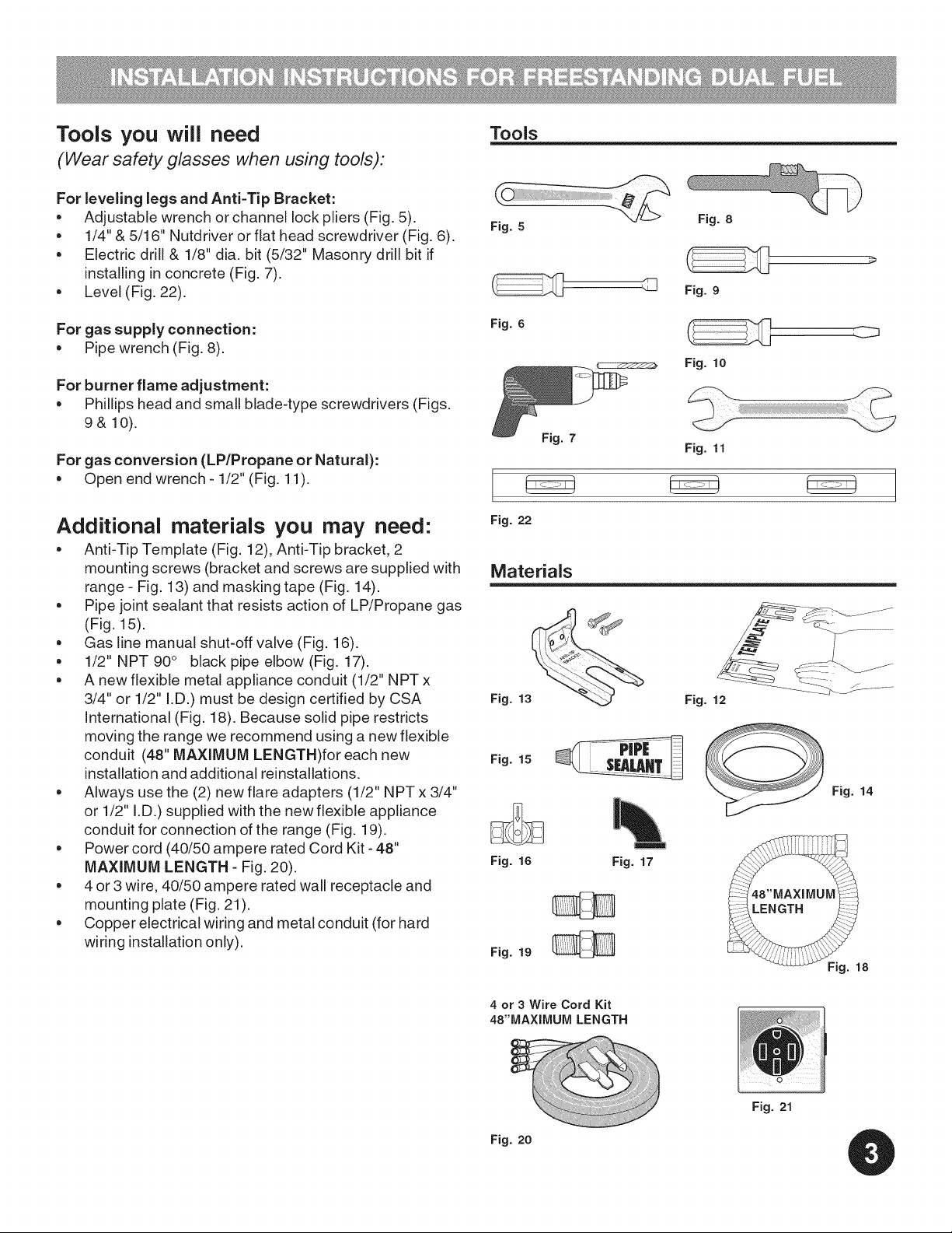
Tools you will need
(Wear safety glasses when using tools):
For leveling legs and Anti-Tip Bracket:
= Adjustable wrench or channel lock pliers (Fig. 5).
= 1/4" & 5/16" Nutdriver or flat head screwdriver (Fig. 6).
Electric drill & 1/8" dia. bit (5/32" Masonry drill bit if
installing in concrete (Fig. 7).
= Level (Fig. 22).
Tools
Fig. 5
,.B
Fig. 8
Fig. 9
For gas supply connection:
= Pipe wrench (Fig. 8).
For burner flame adjustment:
Phillips head and small blade-type screwdrivers (Figs.
9& 10).
For gas conversion (LP/Propane or Natural):
Open end wrench - 1/2" (Fig. 11).
Additional materials you may need:
= Anti-Tip Template (Fig. 12), Anti-Tip bracket, 2
mounting screws (bracket and screws are supplied with
range - Fig. 13) and masking tape (Fig. 14).
Pipe joint sealant that resists action of LP/Propane gas
(Fig. 15).
Gas line manual shut-off valve (Fig. 16).
1/2" NPT 90° black pipe elbow (Fig. 17).
A new flexible metal appliance conduit (1/2" NPT x
3/4" or 1/2" I.D.) must be design certified by CSA
International (Fig. 18). Because solid pipe restricts
moving the range we recommend using a new flexible
conduit (48" MAXIMUM LENGTH)for each new
installation and additional reinstallations.
Always use the (2) new flare adapters (1/2" NPT x 3/4"
or 1/2" I.D.) supplied with the new flexible appliance
conduit for connection of the range (Fig. 19).
Power cord (40/50 ampere rated Cord Kit - 48"
MAXIMUM LENGTH - Fig. 20).
= 4 or 3 wire, 40/50 ampere rated wall receptacle and
mounting plate (Fig. 21).
= Copper electrical wiring and metal conduit (for hard
wiring installation only).
Fig. 6
Fig. 22
Fig. 15
Fig. 16
Fig. 19
Fig. 7
Fig. 10
Fig. 11
Fig. 12
Fig. 14
Fig. 17
4 or 3 Wire Cord Kit
48"MAXIMUIVI LENGTH
Fig. 20
Fig. 21
Page 4
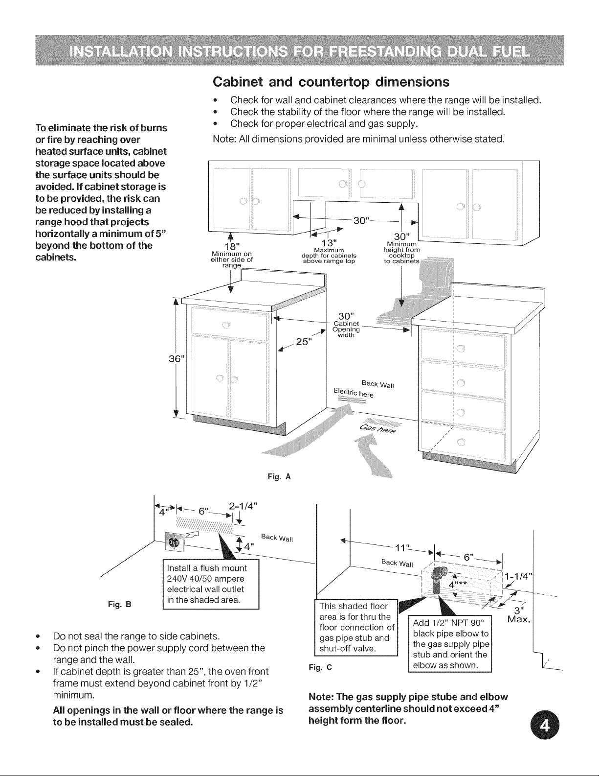
To eliminate the risk of burns
or fire by reaching over
heated surface units, cabinet
storage space located above
the surface units should be
avoided, if cabinet storage is
to be provided, the risk can
be reduced by installing a
range hood that projects
horizontally a minimum of 5"
beyond the bottom of the
cabinets.
Cabinet and countertop dimensions
• Check for wall and cabinet clearances where the range will be installed.
Check the stability of the floor where the range will be installed.
Check for proper electrical and gas supply.
Note: All dimensions provided are minimal unless otherwise stated.
18" 13"
Minimum on depth for cabinets
either side of above ramge top
Maximum
30"
Cabinet
Opening
width
Fig. A
Back Wall
Install a flush mount
240V 40/50 ampere
electrical wall outlet
Fig. B
in the shaded area.
Do not seal the range to side cabinets.
Do not pinch the power supply cord between the
range and the wall.
If cabinet depth is greater than 25", the oven front
frame must extend beyond cabinet front by 1/2"
minimum.
All openings in the wall or floor where the range is
to be installed must be sealed.
Back Wall
11" I
Back Wall _ .......................
This shaded floor
area is for thru the
floor connection of
gas pipe stub and
shut-off valve.
Fig. C
Add 1/2" NPT 90°
black pipe elbow to
the gas supply pipe
stub and orient the
elbow as shown.
Note: The gas supply pipe stube and elbow
assembly centerline should not exceed 4"
height form the floor.
Max.
Page 5

Installation with cabinets and wall
Fig. D
Anti-tip installation
IMPORTANT SAFETY WARNING!
Anti-tip bracket installation instructions
=
Locate the Bracket Using the Template - (Bracket
may be positioned on either the left or right side of the
range. Refer to Figs. 24 thru 26 to position the bracket
iftemplate is not available). Mark the floor or wall
where left or right side of the range will be located. If
rear of range isagainst wall or no further than 1-1/4"
from wall when installed, you may use the wall or floor
mount method. If molding is installed and does not
allow the bracket to fit flush against wall, remove
molding or mount bracket to floor. For wall mount (Fig.
24), locate the bracket by placing the back edge of the
template against rear wall and the side edge of
template on the mark made referencing the side of the
range. Place bracket on top of template and mark
location of the screw holes in wall. If rear of range is
further than 1-1/4" from wall when installed, attach
bracket to the floor. For floor mount (Figs. 24 or 25),
locate the bracket by placing back edge of the
template where the rear of the range will be located.
Mark the location of the screw holes shown in
template.
.
Drill Pilot Holes & Fasten Bracket - Drill 1/8" pilot
hole where screws are to be located (Fig. 23). If
bracket is to be mounted to the wall, drill pilot hole at
an approximate 20° downward angle. If bracket isto
be mounted to masonry or ceramic floors, drill 3/16"
pilot hole 1-3/4" deep. The screws provided may be
used in wood or concrete material. Use 5/16" nut-
driver or flat head screwdriver to secure the bracket in
place.
To reduce the risk of tipping of the range, the range
must be secured to the floor by properly installed anti-
tip bracket and screws packed with the range. Failure
to install the anti-tip bracket will allow the range to tip
over if excessive weight is placed on an open door or if
a child climbs upon it. Serious injury might result from
spilled hot liquids or from the range itself.
If range is ever moved to a different location, the anti=
tip brackets must also be moved and installed with the
range.
Instructions are provided for installation in wood or
cement fastened to either the floor or wall. When
installed to the wall, make sure that screws completely
penetrate dry wall and are secured inwood or metal.
When fastening to the floor or wall, be sure that screws
do not penetrate electrical wiring or plumbing.
=
Level & Position Range - Level range by adjusting the
(4) leveling legs with a wrench. Note: A min. clearance
of 1/8" is required between bottom of range and
leveling legs to allow room for bracket. Slide range
back into position (Fig. 26). Remove lower panel or
storage drawer to visually check that rear leveling leg
is inserted into and fully secured by the bracket. For
models with a warmer drawer or broiler compartment,
grasp the top rear edge of the range and carefully
attempt to tilt it forward. Use a level to check your
adjustments (Fig. 27).
Fig. 23
Page 6

Anti=tip bracket installation instructions
Electrical requirements
FASTEN BRACKET (WALL OR FLOOR MOUNTING)
-_1 1_==1=1/4'' Max.
Leveling Leg -- i_
t J
_F Wall M°unt
-- Wall Plate
Floor Mount L-Anti=Tip Bracket Fig. 24
FASTEN BRACKET (FLOORMOUNTINGONLY)
Leveling Leg --
_-- More Than
1=1/4"
i
Fig. 25
3 & 4- Wire electrical wall Receptacle types &
recommended mounting orientation on wall
Required for new and
remodeled installations
4-Wire Wall
receptacle (14-50R)
Allowed for
existing installations
3 Wire Wall
receptacle (10-50R)
Fig. 28
Electrical connection requirements
This appliance must be properly installed and grounded by
aqualified technician inaccordance with the National Electrical
CodeANSVNFPA No. 70-- latest edition -- and local electrical
code requ irement s.
This appliance may be connected by means of permanent
"Hard Wiring" or "Power Supply Cord Kit."
When hard wiring, do not leave excess wire in range
compartment. Excess wire inthe range compartment may not
allow the access cover to be replaced properly, and could
create a potential electrical hazard ifwires become pinched.
Connect only as instructed under "WIRING INSTRUCTIONS"
in Step Bof the Installation Steps. When using flexibleconduit
or range cable use flex connector or range cable strain relief
(See Fig. 32 on page 7).
Fig. 27
Fig. 26
NOTE: Only usecopper wire inconnection toterminal block.
Models Requiring Power Supply Cord Kit
RISK OF FIRE OR ELECTRICAL SHOCK MAY OCCUR IFAN
INCORRECT SIZE RANGE CORD KIT IS USED, THE
INSTALLATION INSTRUCTIONS ARE NOT FOLLOWED OR
STRAIN RELIEF BRACKET IS DISCARDED.
This appliance may be connected by means of a power
supply cord. Only a power supply cord kit rated at 125/250
volts minimum, and marked for use with ranges shall be
used. See chart (Fig.29) for cord kit ampere rating information.
Cord must haveeither four (4)or three (3)conductors (See Fig.
28). Terminals on end of wires must be either closed loop or
open-end spade lugs with upturned ends. Cord must have
strain relief clamp. See Step B in Installation Steps for 4 or
3 - Wire connections.
Page 7

Range installations steps
Install the power cord.
The rear access cover must be removed. To remove, loosen
center screw (one screw) and remove access cover. The
terminal block will then be accessible (See Fig. 30).
Range Connection Opening Size Chart
Supply Cord Kit ampere rating information. See serial plate on range
for kilowatt rating data.
Fig. 30
Cord Kit
Ampere
Rating
Fig. 29
Diameter (inches) of Range
connection Opening
Permanent
Cord Kit Wiring
1-3/8 in. 1-1/8 in.
1-3/8 in. 1-3/8 in.
Rear
of Range
See Serial Plate on Range for
KW Rating
120/240 Volts 120/208 Volts
8.8-16.5 KW 7.9-12.5 KW 40/50 Amp
16.6-22.5 KW 12.6-18.5 KW 50 Amp
/
Remove
Access
Cover to install
Power Cord.
Replace after
installation.
Wiring instructions
(4-wire connection - See fig. 33)
Before wiring the range review the suggested power
source location drawing in Fig. 2. If connecting to a 4-Wire
electrical system (new branch-circuit or mobile home
requires 4-Wire connection):
Power cord instructions
1. Followthemanufacturer'sinstallationinstructions
supplied with the strain relief and install (Also see
Figs. 29, 30, 31 & 32).
2. Insert the end connectors for Line 1, Line 2 and Neutral
and tighten securely to the terminal block.
IMPORTANT NOTE: DO NOT LOOSEN the factory
installed nut connections which secure the range
wiring to the terminal block. Electrical failure or loss of
electrical connection may occur if these 3 nuts are
loosened or removed.
3. You must disconnect the ground strap. Remove
the factory installed ground screw & plate to release
the copper ground strap from the frame of the
appliance. Cut and discard the copper ground strap &
plate. KEEP the ground screw.
4. Connect the ground wire (Green) lead with the eyelet to
the frame of the appliance with the ground screw using
the same hole in the frame where the ground screw
was originally installed (See Fig. 33).
5. Make sure all screws are tightened securely and
replace the rear access cover (See Fig. 30).
1-1/8" Dia.
Knockout
(See Chart)
Mounting
Plate \
1-3/8"
Hole
(See Chart)
7/8" Dia.
Hole
(See Chart)
Fig. 31
Pocket
for Cable
Mounting Plate
Power
Cord Strain
Relief Bushing
Separate Power Cord
Strain Relief Bushing
before installation
Fig. 32
Page 8

Range installation instructions
OR _S _ 3-Wire connection instructions
(for existing installations ONLY
See Fig. 34)
Power Cord Connection
1. Followthemanufacturer'sinstallationinstructions
supplied with the strain relief and install (Also see
Figs. 29, 30 & 31).
2. Insert the end connectors for Line 1, Line 2 and Neutral
and tighten securely to the terminal block (See Fig. 34).
iMPORTANT NOTE: DO NOT LOOSEN the factory
installed nut connections which secure the range
wiring to the terminal block. Electrical failure or loss of
electrical connection may occur if these 3 nuts are
loosened or removed.
3. Make sure all connections are tightened securely and
replace the rear access cover (See Fig. 30).
Grounding instructions (for 3-Wire
connections ONLY)
A ground strap is installed on this range which connects
the center terminal of the terminal block (neutral) to the
range chassis. The ground strap is connected to the range
by the center, lowest screw (See Fig. 34). The ground strap
must not be removed unless national or local codes do not
permit use of ground strap.
NOTE: If the ground strap is removed for any reason, a
separate ground wire must be connected to the separate
ground screw attached to the range chassis and to an
adequate ground source.
For 3 & 4=Wire permanent connections ONLY
4-Wire Connection
3 Factory installed connections
(DO NOT LOOSEN)
Terminal
block
Connect
line 1
here
Cut ground
strap,
ground strap
& ground plate
Connect gre_
insulated copper
ground wire with
ground screw here
NOTES:
Install strain-relief
bushing. Center or white
wire must always be
attached to the center
terminal on block
3-Wire Connection
Connect
line 1
here
Terminal
block
3 Factory installed connections
(DO NOT LOOSEN)
Connect
neutral
(white or
center) here
Connect
line 2
here
Fig. 33
Connect
neutral
(white or
center) here
3 =Wire permanent connection =follow Steps
1,2 & 5 below.
4 - Wire permanent connection =follow Steps
1 thru 5 below.
Before wiring the range, review the suggested power
source location drawings in Fig. A & B. Ifconnecting to a
4-Wire electrical system (new branch-circuit or mobile
home requires 4-Wire connection):
1. (3 & 4 =Wire permanent connections) Follow the
manufacturer's installation instructions supplied with
the strain relief and install.
Ground strap
Ground screw
& ground
NOTES:
Install strain-relief
bushing. Center or white
wire must always be
attached to the center
terminal on block
Connect
line 2
here
Fig. 34
Page 9

Range installations steps FOR 3 & 4-Wire Permanent Connections
2. (3 & 4 - Wire Permanent Connections) Strip
insulation away from the ends of the permanent wiring
for Line 1, Line 2, Neutral (also strip ground wire on 4-
Wire Connections). Tighten all 3 wire leads to the
terminal block (Follow wire locations shown in Fig. 35).
iMPORTANT NOTE; DO NOT LOOSEN the factory
installed nut connections which secure the range
wiring to the terminal block. Electrical failure or loss of
electrical connection may occur if these 3 nuts are
loosened or removed. NOTE: For 3=Wire Permanent
Connections skip Steps 3 & 4 and continue with
Step 5.
3. {4=Wire Permanent Connection ONLY) Disconnect
the ground strap. Remove the factory installed ground
screw & plate to release the factory installed copper
ground strap from frame of the appliance. Cut and
discard the copper strap from the terminal block.
KEEP the ground screw, ground plate and go to Step
4.
4. (4-Wire Permanent Connection ONLY} Connectthe
ground wire lead (Green) to the frame of the appliance
using the ground screw & plate as shown in Fig. 36.
Be sure to install using the same hole inthe frame
where the ground screw was originally installed.
5. (3 & 4 =Wire Permanent Connections} Make sure all
connections are tightened securely and replace the
rear access cover (See Fig. 30).
PROPER
GROUND FOR
4-WIRE
ND PERMANENT
GROUND
SCREW
,tp=GROUND
WIRE LEAD
CONNECTION
Fig. 36
NOTE: Non-terminated field wire compression
connections must be set at approximately 22in./Ibs.
Always use 10 ga. wire or larger.
Pressure
Regulator
Location and
Installation
of
Gas
Supply
Pressure
Regulator Flare
,_=Tighten all 3 Terminal
wire leads block
Line 2
plate
Ground strap
) Flexible Appliance
Conduit
.............Adaptor Shutoff Black Pipe
Adaptor
Fig. 37 Off
Page 10

Range installation instructions
Provide an adequate gas supply.
This range is pre-set to operate on 4" natural gas manifold
pressure. A convertible Pressure Regulator isconnected to
the manifold and MUST be connected in series with the
gas supply line (Refer to Fig. 37). If the LP/Propane
conversion kit has been used, follow instructions provided
with the kit for converting the pressure regulator to LP/
Propane use. The LP Kit can be found on the back side of
the range or ordered from your dealer.
Care must be taken during installation of range not to
obstruct the flow of combustion and ventilation air. The
gas supply line should be 1/2" or 3/4" I.D.
For proper operation, the maximum inlet pressure to the
regulator should be no more than 14 inches of water
column pressure. The inlet pressure to the regulator must
be at least 1 inch greater than regulator manifold pressure.
Examples: If regulator is set for natural gas 4 inch manifold
pressure, inlet pressure must be at least 5 inches; if
regulator has been converted for LP/Propane gas 10 inch
manifold pressure, inlet pressure must be at least 11
inches. Leak testing of the appliance shall be conducted
according to the instructions in Step E.
Do not allow the Pressure Regulator to turn
on pipe when tightening fittings.
4.) Attach flexible Appliance Conduit to Flare Adapter on
Pressure Regulator (Figs. 18 & 37).
5.) Install 2nd Flare Adapter* to external manual Shut-Off
Valve (Figs. 19 & 37).
6.) Attach flexible Appliance Conduit to Flare Adapter on
Shut-Off Valve (Fig. 37).
7.) After making these connections, check for gas leaks.
Turn the gas supply on to the range and use a liquid leak
detector at alljoints and cond uits to chec kfor leaks inthe
system.*Note: Be sure to use the 2 Flare Adapters
supplied with the Flexible Conduit Kit.
Do not use a flame to check for gas leaks.
Checking Manifold Gas Pressure:
Disconnect the range and its individual shut-off valve from
the gas supply piping system during any pressure testing
of that system at test pressures greater than 14" of water
column pressure (approximately 1/2" psig). The appliance
must be isolated from the gas supply piping system by
closing its individual manual shut-off valve during any
pressure testing of the gas supply piping system at test
pressures equal to or less than 14" of water column
pressure (approximately 1/2" psig).
Seal the wall and floor openings
(Refer to Figs. 1, 2 & 3).
Seal any openings inthe wall behind the range and in the floor
under the range after gas supply line is installed.
Connect the range to the gas supply
(refer to Fig. 37).
Before connecting gas supply to range, review the
suggested power source location drawings (Figs. 1,3 &
4). To prevent leaks apply pipe joint sealant on all male
(outside) pipe threading. The Pressure Regulator can be
found mounted to the lower left rear of range (See Fig 37).
To install the gas supply:
1.) Install 1/2" NPT 90° Black Pipe Elbow to the gas supply
pipe stub (See Figs. 3, 17 & 37)
2.) Install an external gas Shut-Off Valve (manual) to gas
supply line inan easily-accessible location outside of the
range. Be sure you know how and where to shut-off the
gas supply to the range (Figs. 16 & 37).
3.) Install FlareAdapter*togasPressureRegulator(Figs. 19
& 37).
If it should be necessary to check the manifold gas
pressure, connect manometer (water gauge) or other
pressure device to the top burner right rear orifice. Using
a rubber hose with inside diameter of approximately 1/4,"
hold tubing down tight over orifice. Turn burner valve on.
For an accurate pressure check have at least two (2) other
top burners burning. Be sure the gas supply (inlet)
pressure is at least one inch above specified range
manifold pressure. The gas supply pressure should never
be over 14" water column. When properly adjusted for
Natural Gas the manifold pressure is 4" (For LP/Propane
Gas the manifold pressure is 10").
Read the electrical connection details
below. Plug the range into the wall
receptacle.
Before servicing, disconnect electrical
supply at circuit breaker, fuse or Power Cord.
PLEASE READ CAREFULLY! For
personal safety, this product must be properly grounded.
Page 11

Range installations steps
Carefully slide range into cabinet
opening.
Carefully slide range intocabinet opening while inserting
rear leveling leg into and FULLY ENGAGING THE ANTI-TIP
BRACKET (See Fig. 26). Make sure that the flexible
appliance conduit (Fig. 18) and the power cord (Fig. 20)
folds into the remaining open floor area behind the range
warmer or storage drawer. Make sure that the flexible
appliance conduit does not become pinched or kinked!
Pre-shape the flexible appliance conduit and power cord if
necessary to insure that the range slides intocabinet
opening properly. Be sure to check level of the range by
placing a level horizontally on an oven rack (See Fig. 27).
Surface burner heads, cap & grates.
It is very important to make sure that all of the surface
burner heads, surface burner caps and surface burner
grates are installed correctly.
Your appliance was shipped with the burner heads and
burner caps assembled in the correct locations (Fig. 38).
Should you need to re-install the burner caps please refer
to the Use & Care guide for more information.
REMEMBER -- DO NOT ALLOW SPILLS, FOOD,
CLEANING AGENTS OR ANY OTHER MATERIAL TO
ENTERTHE
GAS ORIFICE HOLDER OPENING. Always keep the Burner
Caps and Burner Heads in place whenever the surface
burners are in use.
Check electric ignition of surface burners.
Operation of electric igniters should be checked after range
and supply line connectors have been carefully checked for
leaks and range has been connected to electric power.
1. To check for proper lighting, push in and turn surface
burner knob counterclockwise to the _(lite) position.
You will hear the igniter sparking ( Fig. 39).
2. The surface burner should light when gas isavailable
to the top burner. Purge air from supply lines by
knob in the _(lite) position until burnerleaving ignites.
Each burner should light within four (4) seconds in
normal operation after air has been purged from supply
lines.
3. Visually check that the burner has lit. Once the burner
lites, turn the control knob out of the _(lite)
4. The range has separate electrodes (igniters) for each
burner. Try each knob separately until all burner valves
have been checked.
position.
1. 2 Standard burners- 9,500 BTU.
2. Min-2-Max TM - double burner- 18,000 BTU.
3. Large burner- 14,000 BTU.
4. PerfectSimmer burner TM-5,000 BTU Fig. 38
Fig. 39
Adjust the "LO" setting of surface
burner valve (for linear flow valves
only).
If burner goes out, reset control to OFF.
Remove the burner control knob.
Use a thin-bladed screwdriver and adjust the inner burner
flame size with the right-hand set screw (See Fig. 40).
Adjust the outer burner flame size with the lower set screw
(See Fig. 40). Turn counterclockwise to increase flame size.
Turn clockwise to decrease flame size.
Test to verify if "LO or LOW" setting should be adjusted
(right front position ONLY)
1. Push inand turn knob to (lite) until burner ignites.
2. Push in and quickly turn knob to LOWEST POSITION.
3. If burner goes out, reset control to OFR
4. Remove the burner control knob.
5. Use a thin-bladed screwdriver and adjust the inner
burner flame size with the right-hand set screw (See Fig.
40). Adjust the outer burner flame size with the lower
set screw (See Fig. 40). Turn counterclockwise to
increase flame size. Turn clockwise to decrease
flame size.
Page 12

Range installations steps
Ri__ght-handburner only_
Inner burner flame
adjustment screw
Test to verify if "LO or LOW" setting should be adjusted (all
other positions):
1. Follow steps a thru d above.
2. Insert a thin-bladed screwdriver into the hollow valve
stem and engage the slotted screw inside. Flame size
can be increased or decreased with the turn of the
screw. Turn counterclockwise to increase flame size.
Turn clockwise to decrease flame size.
After installation is complete, make all
controls are left in the OFF position.
Care, cleaning and maintenance
Refer to the Use & Care Guide for cleaning
instructions. If removing the range is necessary for
cleaning or maintenance, shut off the gas supply.
Disconnect the gas and electrical supply. If the gas or
electrical supply is inaccessible, lift the range slightly at
the front and pull out away from the wall. Pull only as far
as necessary to disconnect the gas and electrical supply.
Finish removing the range for servicing and cleaning.
Reinstall in reverse order making sure to level the range
and check gas connections for leaks. See anti-tip
instructions for proper anti-tip anchoring instructions.
\
\!
Outer burner flame '_I_
adustment screw
All other surface burners
Before you call for service
Refer to the Use & Care Guide for cleaning
instructions. If removing the range is necessary for
cleaning or maintenance, shut off the gas supply.
Disconnect the gas and electrical supply. If the gas or
electrical supply is inaccessible, lift the range slightly at
the front and pull out away from the wall. Pull only as far
as necessary to disconnect the gas and electrical supply.
Finish removing the range for servicing and cleaning.
Reinstall in reverse order making sure to level the range
and check gas connections for leaks. See page 3 of this
document for proper anti-ti p anchoring instructions.
Model and serial number location
The Serial Plate is located on the right-hand surface of the
oven front frame at the storage or warmer drawer; or the
lower panel area (See Fig. 41).
When ordering parts for or making inquires about your
range, always be sure to include the model and serial
numbers and a lot number or letter from the Serial Plate on
your range. The Serial Plate will also inform you of the
rating of the burners, the type of fuel and the pressure the
range was adjusted for when it left the factory.
Serial plate is located on the Iowerrig front
frame of the appliance. Alternate location
may be under cooktop.
 Loading...