

Electrolux EW30WD55GS User Manual [en, es, fr]
WARM & SERVE DRAWER INSTALLATION INSTRUCTIONS
D
A
F
E
C
B
WARNING
Canada United States
INSTALLATION AND SERVICE MUST BE PERFORMED
BY A QUALIFIED INSTALLER.
IMPORTANT: SAVE FOR LOCAL ELECTRICAL INSPECTOR'S USE.
READ AND SAVE THESE INSTRUCTIONS FOR FUTURE REFERENCE.
FOR YOUR SAFETY: Do not store or use gasoline or other
flammable vapors and liquids in the vicinity of this or any other appliance.
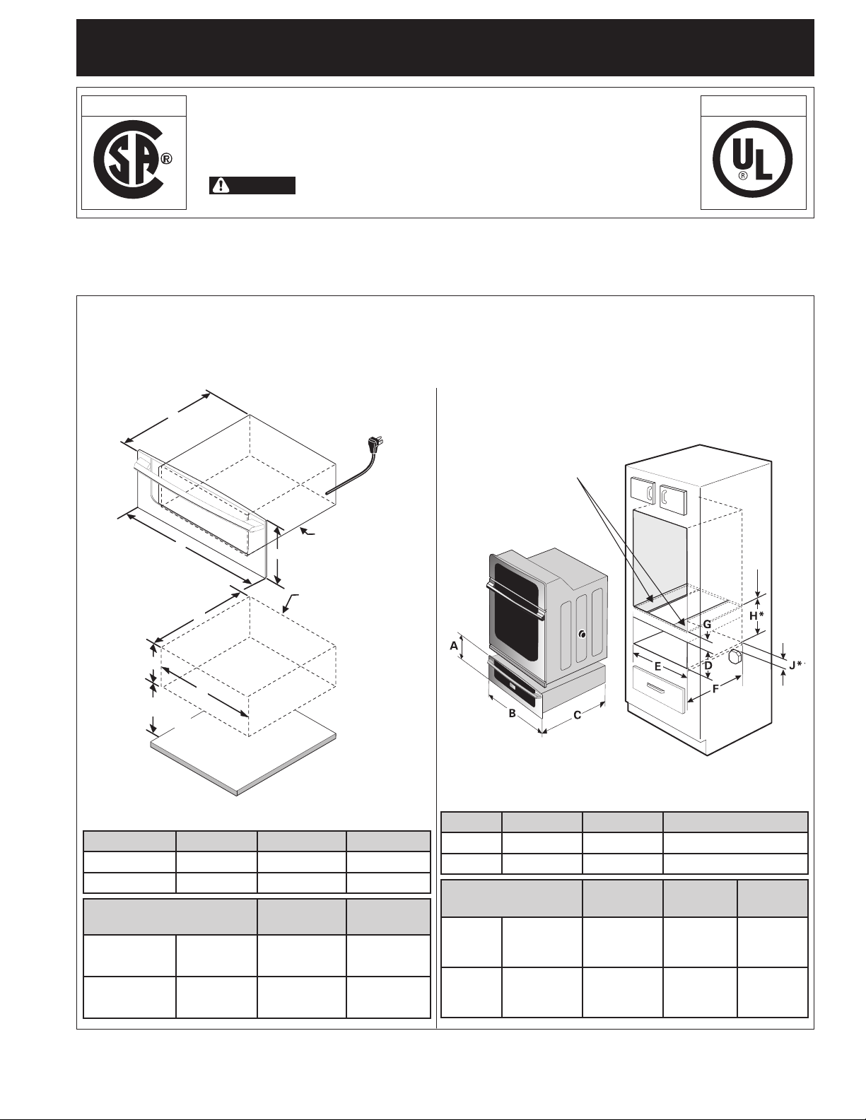
GENERAL INFORMATION: The Warm & Serve Drawer
can be used as a stand alone appliance or combine with a
built-in oven mounted above.
Warm & Serve Drawer Dimensions
NOTE: A 60" (152,4 cm) long cable is supplied with
the Warm & Serve Drawer.
Stand Alone Installation
60" (152,4 cm)
Cord
IMPORTANT: The warmer drawer must be installed on
a leveled surface from left to right, rear to front and the
surface must be capable of supporting 100 lbs (45,4 Kg).
IMPORTANT: The Warm & Serve Drawer ru ns off a
single phase three-wire 120 volt, 60 hertz, AC only
electrical supply with ground.
Combination Warm & Serve Drawer/ 27" (68,6 cm) or
30" (76,2 cm) Built-in Oven Installation
Caution: Two 3" (7,6 cm) wide X
3/4" (1,9 cm) thick planks have to
be install and they should be able to
support 200 pounds. (90,7 Kg)
Warm and Serve
Drawer
Bottom of oven cutout
Minimum distance to floor
4½" (11,4 cm)
Warm and Serve
Cutout
FLOOR
H* = 11 7/8" (30,2 cm) Min. is a Critical
dimension and has to be respected.
J** = 3" (7,6 cm) Max. Electrical Junction Box for wall oven must be
lower than warmer drawer cutout.
A. HEIGHT B. WIDTH C. DEPTH
3
/8" (59,4 cm)
3
/8" (59,4 cm)
F. CUTOUT
DEPTH
G. HEIGHT
Depends on critical
dimension H
Depends on critical
dimension H
27" Models 11 ¼" (28,6 cm) 27" (68,6 cm) 23
30" Models 11 ¼" (28,6 cm) 30" (76,2 cm) 23
27" Models - Min. 9
A. HEIGHT B. WIDTH C. DEPTH
D. CUTOUT
HEIGHT
7
/8" (25,1 cm) 25 ½" (64,8 cm) 23 5/8" (60 cm)
E. CUTOUT
WIDTH
3
/8" (59,4 cm)
3
/8" (59,4 cm)
F. CUTOUT
DEPTH
27" Models 11 ¼" (28,6 cm) 27" (68,6 cm) 23
30" Models 11 ¼" (28,6 cm) 30" (76,2 cm) 23
27" - Min. 9
D. CUTOUT
HEIGHT
7
/8" (25,1 cm) 25 ½" (64,8 cm) 23 5/8" (60 cm) 2" (5,1 cm)
E. CUTOUT
WIDTH
Max. 10 ¼" (26 cm) 25 ¾" (65,4 cm) 24" (61 cm)
Max. 10 ¼" (26 cm) 25 ¾" (65,4 cm) 24" (61 cm)
30" Models - Min. 9
7
/8" (25,1 cm) 28 ½" (72,4 cm) 23 5/8" (60 cm)
Max. 10 ¼" (26 cm) 28 ¾" (73 cm) 24" (61 cm)
30" - Min. 9 7/8" (25,1 cm) 28 ½" (72,4 cm) 23 5/8" (60 cm) 2" (5,1 cm)
Max. 10 ¼" (26 cm) 28 ¾" (73 cm) 24" (61 cm)
Printed in the USA
P/N 318201809 (0901) Rev. D
English – pages 1-3; Español – páginas 4-6
Français – pages 7-9; Notes - pages 10-12
1
WARM & SERVE DRAWER INSTALLATION INSTRUCTIONS
Important Notes to the Installer
1. Read all instructions contained in these installation
instructions before installing appliance.
2. Remove all packing material from appliance before
connecting the electrical supply.
3. Observe all governing codes and ordinances.
4. Be sure to leave these instructions with the consumer.
Important Note to the Consumer
Keep these instructions for future reference.
IMPORTANT SAFETY
INSTRUCTIONS
• Be sure your appliance is installed and plugged into
a 120 Volt grounded outlet.
• This appliance must be electrically grounded in
accordance with the National Electrical Code ANSI/
NFPA No. 70—latest edition in the United States,
or CSA C22.1, Part 1 in Canada, and local code
requirements.
Tools You Will Need
Phillips® Screwdriver
Pencil
Ruler or Tape Measure and Straight-edge
Hand Saw or Saber Saw
Spirit Level
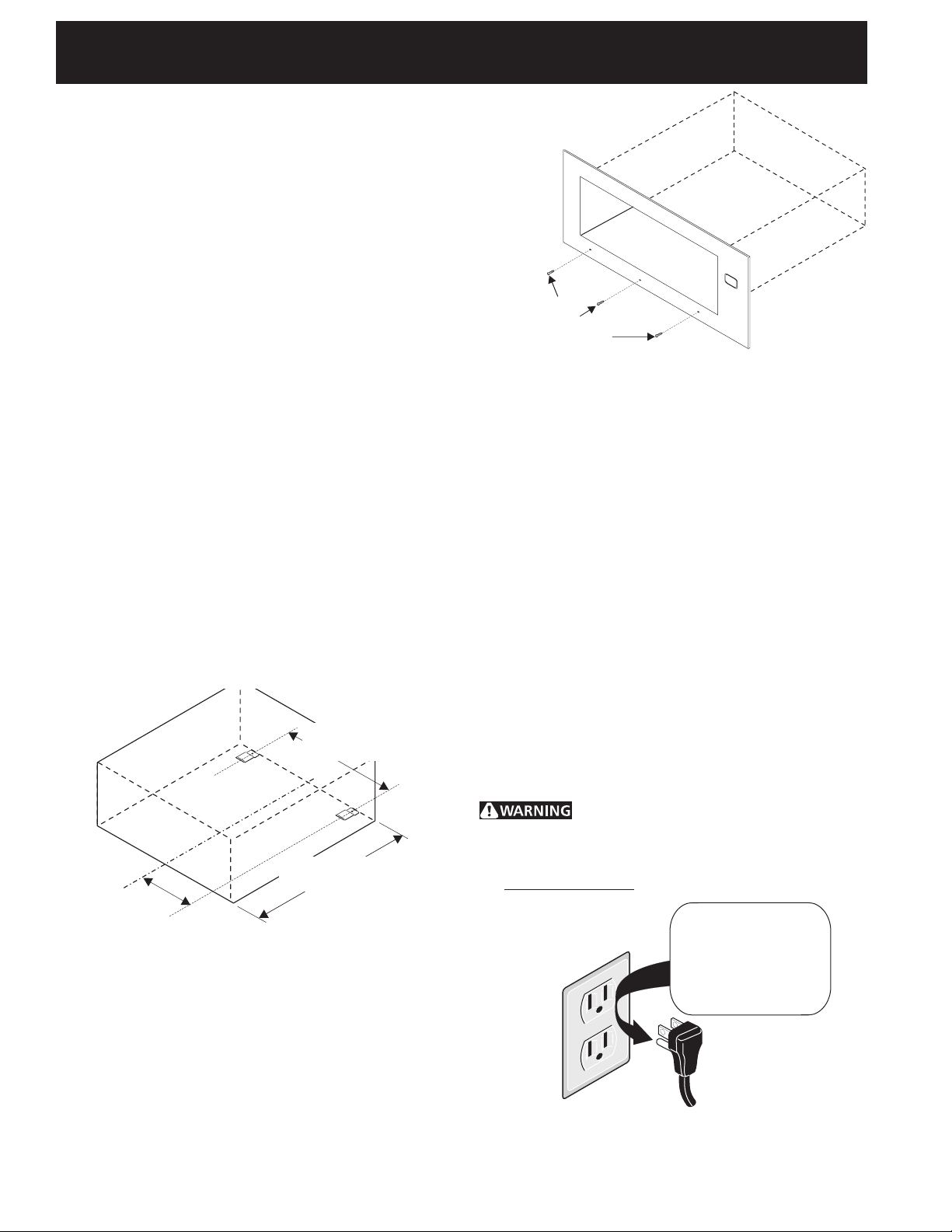
Warm & Serve Drawer Installation
1. Locate the 2 anti-tip brackets supplied as shown on fig. 1.
c
/c 25 5/16"
(64,3 cm)
Use screws
supplied to attach
drawer to front of
cabinet.
Figure 2
Electrical connection
IMPORTANT Please read carefully.
For personal safety, this appliance must be properly
grounded.
The power cord of this appliance is equipped with a
3-prong (grounding) plug which mates with a standard
3-prong grounding wall receptacle to minimize the
possibility of electric shock hazard from the appliance.
The wall receptacle and circuit should be checked by
a qualified electrician to make sure the receptacle is
properly grounded.
Where a standard 2-prong wall receptacle is installed,
it is the personal responsibility and obligation of the
consumer to have it replaced by a properly grounded
3-prong wall receptacle.
Do not, under any circumstances, cut or remove the
third (ground) prong from the power cord.
24" (61 cm) Max.
c
/c 12 21/32"
(32,2 cm)
2. Slide drawer into cutout opening until front frame of
drawer is flush against cabinet. Be careful not to pinch
electrical cord.
3. Remove the drawer as instructed in the Use & Care
Guide and secure drawer housing to cabinet using the
3 nickel-plated screws supplied (see Figure 2). Do not
overtighten screws.
4. The 60" (152,4 cm) appliance power cord can now be
connected into the 120 Volt outlet.
5. Proceed with mounting built-in oven above the drawer
(if applicable). Follow installation instructions provided
with built-in oven. Make sure to use anti-tip brackets
supplied with the built-in oven.
23 5/8" (60 cm) Min.
Figure 1
Disconnect electrical supply cord from
wall receptacle before servicing cooktop.
Preferred Method
Grounding type
wall receptacle
2
Do not, under any
circumstances, cut,
remove, or bypass
the grounding
prong.
Power supply cord with
3-prong grounding plug.
WARM & SERVE DRAWER INSTALLATION INSTRUCTIONS
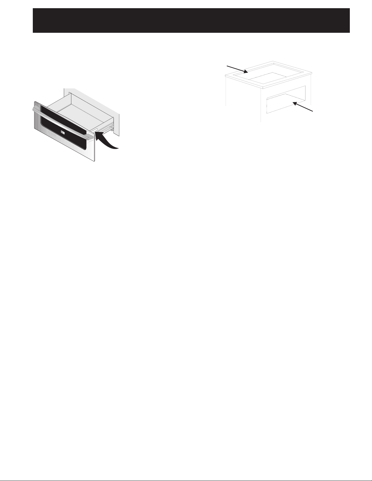
Model and Serial Number Location
The serial plate is located as shown below.
When ordering parts for or making inquiries about your
Warm & Serve Drawer, always be sure to include the
model and serial numbers and a lot number or letter
from the serial plate on your Warm & Serve Drawer.
Serial Plate Location
Combination Warm & Serve Drawer
and Cooktop Installation
Cooktop
Cutout
Warmer
Drawer
Cutout
You can install the warmer drawer in combination with an
electric or gas cooktop. You must follow the specifications
from the installation instructions of the cooktop to avoid
interference with the gas or electric installation.
3
INSTRUCCIONES DE INSTALACIÓN PARA EL CAJÓN CALENTADOR
D
A
F
E
C
B
Canadá Estados Unidos
LA INSTALACIÓN Y EL SERVICIO DEBEN SER EFECTUADOS POR
UN INSTALADOR CALIFICADO.
IMPORTANTE: GUARDE ESTAS INSTRUCCIONES PARA USO DEL INSPECTOR
LOCAL DE ELECTRICIDAD.
LEA Y GUARDE ESTAS INSTRUCCIONES PARA REFERENCIA FUTURA.
PARA SU SEGURIDAD: No almacené ni utilice gasolina u otros
vapores y líquidos inflamables en la proximidad de este o de cualquier otro artefacto.
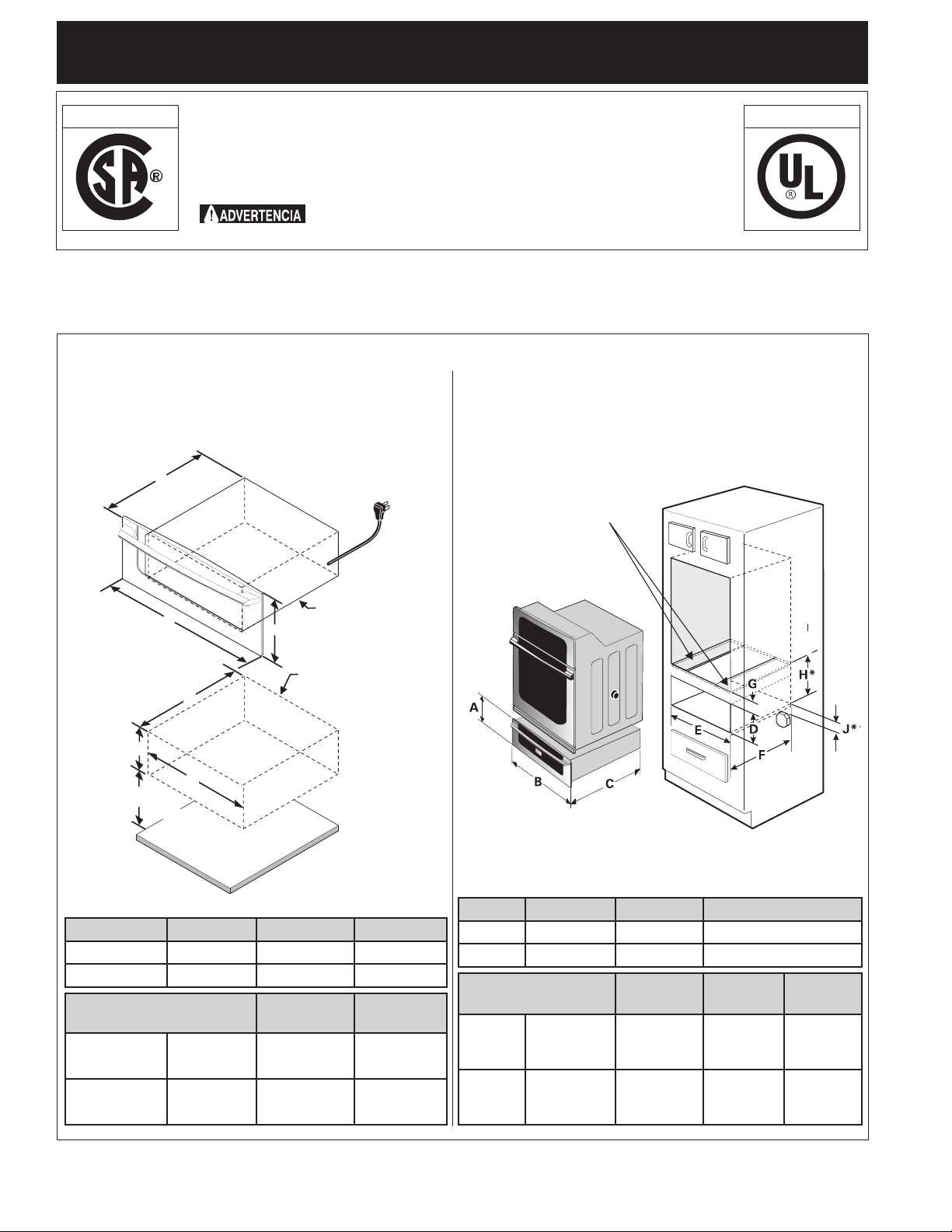
INFORMACIÓN GENERAL: El cajón calentador puede ser
usado como unidad independiente o
en una combinación entre
el cajón calentador y el horno integrado y montado por encima del
cajón.
Dimensiones del cajón calentador
NOTA: Un cable de 60" (152,4 cm) de largo es
suministrado con el cajón calentador.
Instalación de la unidad independiente
Cable de 60"
(152,4 cm)
IMPORTANTE: El cajón calentador debe de estar instalado
con una superficie llana, de la izquierda a la derecha, de la
parte de atrás al frente. La superficie debe poder sostener
100 libras (45,4 Kg).
IMPORTANTE: El ca jón calen tador fun c iona con un
suministro de energía eléctrica de corriente alterna, de
tres cables, de una sola fase, de 120 voltios, 60 hertz con
línea a tierra.
Instalación de la combinación cajón calentador y
horno de 27" (68,6 cm) o 30" (76 cm) integrado
Precaución: Dos tablas de 3"(7,6
cm) por ¾" (1,9 cm) necesitan ser
instaladas y deberán soportar 200
libras (90,7 Kg)
Distancia Mínima del piso
4 1/2" (11,4 cm)
Modelos 27" 11 ¼" (28,6 cm) 27" (68,6 cm) 23
Modelos 30" 11 ¼" (28,6 cm) 30" (76,2 cm) 23
Modelos 27" - Mín. 9
Modelos 30" - Mín. 9
Cajón Calentador
Abertura del Cajón
calentador
Piso
A. ALTO B. ANCHO C. LARGO
3
D. ALTURA DE
LA ABERTURA
7
/8" (25,1 cm) 25 ½" (64,8 cm) 23 5/8" (60 cm)
E. ANCHO DE
LA ABERTURA
Máx. 10 ¼" (26 cm) 25 ¾" (65,4 cm) 24" (61 cm)
7
/8" (25,1 cm) 28 ½" (72,4 cm) 23 5/8" (60 cm)
Máx. 10 ¼" (26 cm) 28 ¾" (73 cm) 24" (61 cm)
/8" (59,4 cm)
3
/8" (59,4 cm)
F. LARGO DE
LA ABERTURA
Parte inferior del horno
H* = 11 7/8" (30,2 cm) Min. es una dimensión
crítica y necesita ser respetada.
J**= 3" (7,6 cm) Máx. La caja para las conexiones eléctricas para el horno
de empotre puede estar de bajo de la abertura del cajón calentador.
A. ALTO B. ANCHO C. LARGO
3
27" Models 11 ¼" (28,6 cm) 27" (68,6 cm) 23
30" Models 11 ¼" (28,6 cm) 30" (76,2 cm) 23
D. ALTURA DE LA
27" - Min. 9
ABERTURA
7
/8" (25,1 cm) 25 ½" (64,8 cm) 23 5/8" (60 cm) 2" (5,1 cm)
E. ANCHO DE
LA ABERTURA
F. LARGO DE
LA ABERTURA
Max. 10 ¼" (26 cm) 25 ¾" (65,4 cm) 24" (61 cm)
/8" (59,4 cm)
3
/8" (59,4 cm)
G. ALTO
Depende de la
dimensión crítica H
30" - Min. 9 7/8" (25,1 cm) 28 ½" (72,4 cm) 23 5/8" (60 cm) 2" (5,1 cm)
Max. 10 ¼" (26 cm) 28 ¾" (73 cm) 24" (61 cm)
Depende de la
dimensión crítica H
Impreso en los EUA
P/N 318201809 (0901) Rev. D
English – pages 1-3; Español – páginas 4-6
4
Français – pages 7-9; Notes - pages 10-12
 Loading...