

Page 1
IMPORTANT
DO NOT REMOVE THIS BAG
OR DESTROY THE CONTENTS
WIRING DIAGRAMS AND SERVICE
INFORMATION ENCLOSED
REPLACE CONTENTS IN BAG
SERVICE DATA SHEET - Microwave Combination Unit with ES700/705 Electronic Oven Control
NOTICE: This service data sheet is intended for use by persons having electrical and mechanical training and a level of knowledge of these subjects generally considered acceptable
in the appliance repair trade. The manufacturer cannot be responsible, nor assume any
liability, for injury or damage of any kind arising from the use of this data sheet.
IMPORTANT NOTE: This unit includes an EOC (electronic oven control). This board is not
eld-repairable.
Safe Servicing Practices
To avoid the possibility of personal injury and/or property damage, it is important that safe
servicing practices be observed. The following are some, but not all, examples of safe
practices.
1. Do not attempt a product repair if you have any doubts as to your ability to complete it
in a safe and satisfactory manner.
2. Before servicing or moving an appliance, remove power cord from electric outlet, trip
circuit breaker to Off, or remove fuse.
3. Never interfere with the proper installation of any safety device.
4. Use only replacement parts specied for this appliance. Substitutions may not comply
with safety standards set for home appliances.
5. Grounding: The standard color coding for safety ground wires is green or green with
yellow stripes. Ground leads are not to be used as current carrying conductors. It is
extremely important that the service technician reestablish all safety grounds prior to
completion of service. Failure to do so will create a potential hazard.
6. Prior to returning the product to service, ensure that:
• All electric connections are correct and secure.
• All electrical leads are properly dressed and secured away from sharp edges,
high-temperature components, and moving parts.
• All uninsulated electrical terminals, connectors, heaters, etc. are adequately
spaced away from all metal parts and panels.
• All safety grounds (both internal and external) are correctly and securely reas-
sembled.
• All panels are properly and securely reassembled.
OVEN CALIBRATION
Set the electronic oven control for normal baking at 350°F. Allow oven to preheat to set
temperature. Obtain an average oven temperature after a minimum of ve cycles. Press the
STOP key to end the Bake mode.
TEMPERATURE ADJUSTMENT
To adjust the temperature settings of the appliance, see instructions listed in the Use and
Care manual.
2-SPEED COOLING FAN
The EOC controls the speed of the cooling fan. The cooling fan is activated at low speed
during any cooking function and will remain on until the oven is cooled down. The high speed
is activated during the broil (with open door) and during clean cycles only when the tempera-
ture is above apporximately 575°F/302°C.
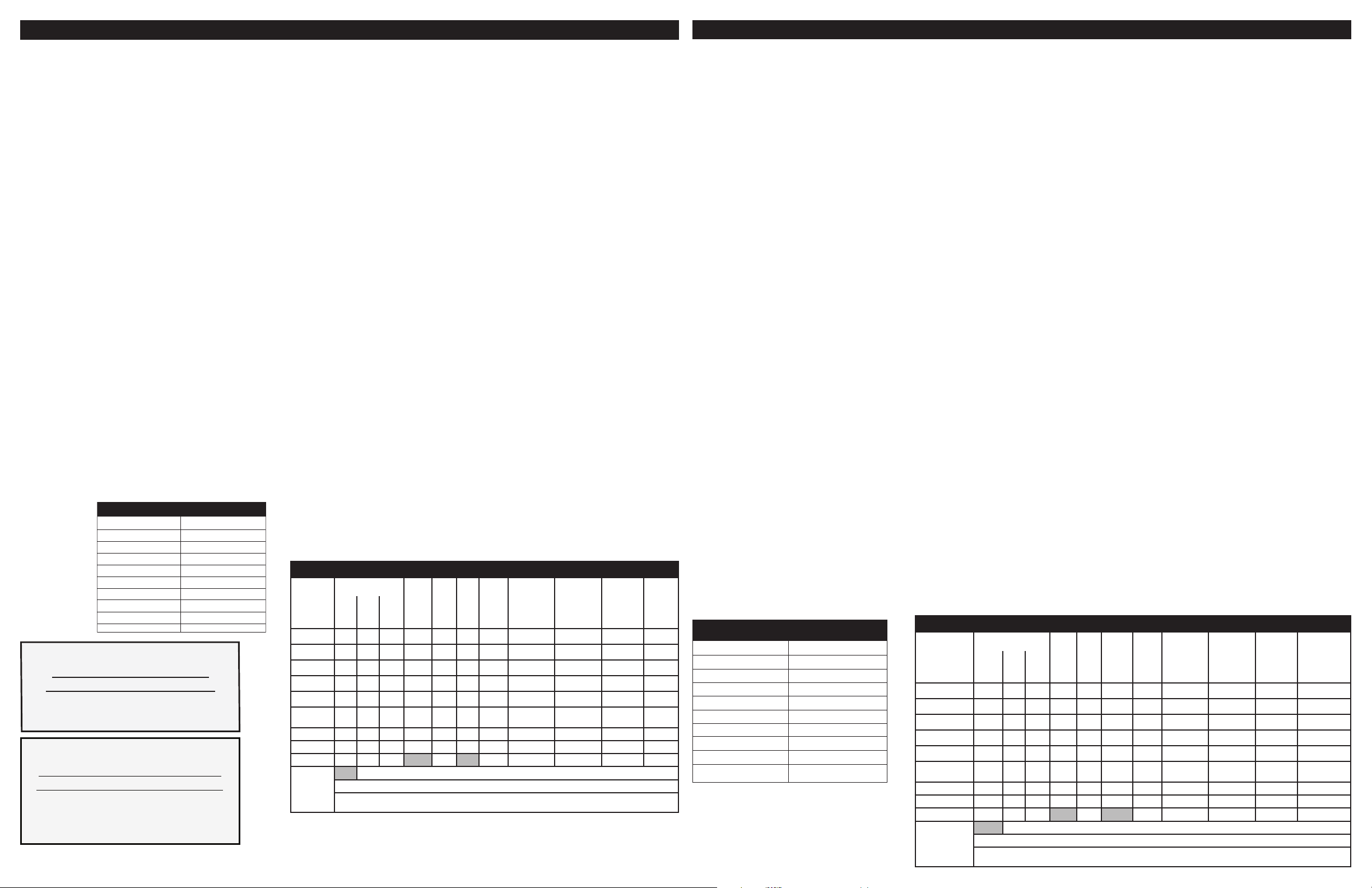
RTD SCALE
Temperature °F (°C)
32 ± 1.9 (0 ± 1.0)
75 ± 2.5 (24 ± 1.3)
250 ± 4.4 (121 ± 2.4)
350 ± 5.4 (177 ± 3.0)
450 ± 6.9 (232 ± 3.8)
550 ± 8.2 (288 ± 4.5)
650 ± 9.6 (343 ± 5.3)
900 ± 13.6 (482 ±7.5)
Probe circuit to case ground
IMPORTANT
N’ENLEVEZ P
DÉTR
UISEZ P
CONTIENT LES SCHÉMAS DE CÂBLAGE ET
LES INFORMATIONS DE RÉPARATION
REMETTRE LE CONTENU
807574902 EN/FR Rev A (13/05)
AS CE SAC OU NE
AS SON CONTENU
DANS LE SAC
Resistance (ohms)
1000 ± 4.0
1091 ± 5.3
1453 ± 8.9
1654 ± 10.8
1852 ± 13.5
2047 ± 15.8
2237 ± 18.5
2697 ± 24.4
Open circuit/infinite resistance
Bake X X X* X* X X X**
Broil X X X X**
Conv. Bake X X X X X X X**
Conv. Roast X X X X X X X**
Clean X X X X X X
Locking /
Unlocking
Light X
Door Open X
Door Closed X X
NOTES Relay will operate in this condition only.
MICROWAVE EXTERNAL COOLING FAN
In addition to the cooling fan located inside the microwave chassis there is a second cooling
fan located on the back of the microwave chassis. This “external” fan is needed to provide
adequate ventilation of the microwave oven. It is controlled by the Appliance Control Board
and should be active anytime the microwave oven is used (convection or microwaves). It
remains active a few minutes after the microwave has ceased its function to allow further
cooling. The fan is equipped with a speed sensor. The sensor is read by the Appliance Control Board. The purpose of this fan speed monitoring is to terminate the microwave activity
if the fan turns abnormally slow or fast. Refer to F43 and F44 error codes in the fault code
descriptions. The Appliance Control Board starts checking the fan speed approximately 5
minutes after a function was started in the microwave. After this 5 minutes start-up period, it
will trigger an alarm at the moment it reads a speed value out of range.
MAGNETRON ASSEMBLY TEST
WARNING: high voltages are present during the cook cycle, so extreme caution
should be observed. Discharge the high voltage capacitor before touching any oven
components or wiring.
To test for an open lament, isolate the magnetron from the high voltage circuit. A continuity
check across the magnetron lament leads should indicate less than 1 ohm.
To test for a shorted magnetron, connect the ohmmeter leads between the magnetron
lament leads and chassis ground. This test should indicate an innite resistance. If there is
little or no resistance the magnetron is grounded and must be replaced.
Power output of the magnetron can be measured by performing a water temperature rise
test. This test should only be used if above tests do not indicate a faulty magnetron and there
is no defect in the following components or wiring: silicon rectier, high voltage capacitor and
power transformer. This test will require a 16 ounce (453 cc.) measuring cup and an accurate
mercury thermometer or thermocouple type temperature tester. For accurate results, the
following procedure must be followed carefully:
1. Fill the measuring cup with 16 oz. (453 cc.) of tap water and measure the temperature
of the water with a thermometer or thermocouple temperature tester. Stir the thermometer or thermocouple through the water until the temperature stabilizes. Record the
temperature of the water.
2. Place the cup of water in the oven. Operate oven at POWER HI(HIGH) selecting more
than 60 seconds cook time. Allow the water to heat for 60 seconds, measuring with a
stop watch, second hand of a watch or the digital read-out countdown.
3. Remove the cup from the oven and again measure the temperature, making sure to stir
the thermometer or thermocouple through the water until the maximum temperature is
recorded.
4. Subtract the cold water temperature from the hot water temperature. The normal result
should be 22 to 43°F (12.2 to 23.8°C) rise in temperature. If the water temperatures are
accurately measured and tested for the required time period the test results will indicate if the magnetron tube has low power output (low rise in water temperature) which
would extend cooking time or high power output (high rise in water temperature) which
would reduce cooking time. Because cooking time can be adjusted to compensate
for power output, the magnetron tube assembly should be replaced only if the water
temperature rise test indicates a power output well beyond the normal limits. The test is
only accurate if the power supply line voltage is 120 volts and the oven cavity is clean.
LOWER OVEN CIRCUIT ANALYSIS MATRIX
ELEMENTS
Conv
Oven
Latch
DLB
Fan
Light
BakeP8BroilP7Conv
* Convection element and fan are used during the preheat of bake.
** Catalyst element (some models) is active during preheat. It can be manually activated or shut off after preheat
using the Fresh Clean/ Air Guard key.
J1-8
P9
J1-7
Motor
J1-4
X
L2 out
P12
Cooling Fan
Low Speed
J1-5
Cooling Fan
High Speed
J1-6
Door Switch
P18-3 / P18-7
Catalyst
Element
J1-3
FICHE DE RÉPARATION - Four Encastré Électrique/Micro-ondes avec ES700/705 Commande Électronique du Four
AVIS: Cette feuille de données d’entretien est destinée aux personnes ayant reçu une formation en électricité et en mécanique, et qui possèdent un niveau de connaissance jugé acceptable dans l’industrie de réparation des appareils électroménagers. Le fabricant ne peut
être tenu responsable, ni n’assumer aucune responsabilité, pour toute blessure ou dommage
de quelque nature que ce soit pouvant résulter de l’utilisation de cette feuille de données.
NOTES IMPORTANTES: Cet appareil inclut un contrôleur de four électronique. Le tableau
de contrôle n’est pas réparable sur place.
PRATIQUES D’ENTRETIEN SÉCURITAIRE
Pour éviter tout risque de blessure et/ou dommage matériel, il est important que des
pratiques d’entretien sécuritaires soient suivies. Voici quelques exemples de pratiques
sécuritaires.
1. N’essayez jamais de réparer un appareil si vous ne croyez pas avoir les compétences
nécessaires pour le faire de manière satisfaisante et sécuritaire.
2. Avant de procéder au service d’entretien ou de déplacer tout appareil ménager,
débranchez le cordon d’alimentation de la prise électrique, réglez le disjoncteur de
circuit à OFF, ou enlevez le fusible et fermez le robinet d’alimentation en gaz.
3. N’entravez jamais l’installation adéquate de tout dispositif de sécurité.
4. Utilisez que les pièces de remplacement énumérées dans le catalogue pour cet appareil. La moindre substitution risque de ne pas être conforme aux normes de sécurité
établies pour les appareils électroménagers.
5. MISE À LA TERRE: La couleur de codage standard des conducteurs de mise à la terre
de sécurité est VERTE ou VERTE À BARRES JAUNES. Les conducteurs de mise à la
terre ne doivent pas être utilisés comme conducteurs de courant. Il est d’une IMPOR-
TANCE CAPITALE que le technicien d’entretien complète toutes les mises à la terre
de sécurité avant de terminer le service. Si cette recommandation n’est pas suivie à la
lettre, il en résultera des risques pour les personnes et les biens.
6. Avant de retourner le produit au service de réparation ou d’entretien, assurez-vous
que:
• Toutes les connexions électriques sont correctes et sécuritaires.
• Tous les conducteurs électriques sont correctement préparés et sécuritairement
à l’abri des bords tranchants, des composants à température élevée, et des
parties mobiles.
• Toutes les bornes électriques, connecteurs, réchauffeurs, etc. dénudés sont
espacés convenablement loin de toute pièce en métal et des panneaux.
• Toutes les mises à la terre de sécurité (interne et externe) sont correctement et
sécuritairement assemblées.
• Toutes les panneaux sont correctement et sécuritairement assemblées.
ÉTALONNAGE DU FOUR
Réglez le régulateur électronique de four pour une cuisson normale à 350 ºF (177 ºC).
Comptez-vous de four préchauffer choisir températures. Vous devez obtenir une tempéra-
ture moyenne de four après 5 cycles. Appuyez sur la touche STOP/CANCEL (arrêt) pour
mettre n au mode de cuisson.
RÉGLAGE DE LA TEMPÉRATURE
Pour régler la température de l’appareil, voir les instructions du guide d’utilisation et d’entretien.
2-VITESSE VENTILATEUR RAFRAÎCHISSANT
Les contrôleurs de four électronique dirige vitesse de le ventilateur rafraîchissant. Le ventilateur rafraîchissant activer à basse vitesse vitesse pendant une cuisson fonction, et il reste
allumé jusqu’à ce que du four refroidir. Le haut débit activer pendant grillage (avec la porte
ouverte) et pendant clean cycles seul quand la température est plus que approximativement
575ºF/302ºC.
ÉCHELLE DU DÉTECTEUR DE TEMPÉRATURE
Température °F (°C)
32 ± 1,9 (0 ± 1,0)
75 ± 2,5 (24 ± 1,3)
250 ± 4,4 (121 ± 2,4)
350 ± 5,4 (177 ± 3,0)
450 ± 6,9 (232 ± 3,8)
550 ± 8,2 (288 ± 4,5)
650 ± 9,6 (343 ± 5,3)
900 ± 13,6 (482 ±7,5)
Circuit de la sonde mise à la
terre à la caisse
À RÉSISTANCE
Résistance (ohms)
Circuit ouvert/résistance infinie
1 000 ± 4,0
1 091 ± 5,3
1 453 ± 8,9
1 654 ± 10,8
1 852 ± 13,5
2 047 ± 15,8
2 237 ± 18,5
2 697 ± 24,4
ÉLÉMENTS
CuissonP8GrilP7Conv
Cuisson X X X* X* X X X**
Gril X X X X**
Cuisson Conv.
Rôtissage Conv
Nettoyage
Verrouillage
Verrouillé
Lampe X
Porte Ouverte
Porte Fermée
NOTES Relais opération de volonté dans cette condition seulement.
X X X X X X X**
X X X X X X X**
X X X X X X
/
* Élément de convection et le ventilateur sont utilisés pendant le préchauffage de cuisson.
** Elément catalyseur (certains modèles) est actif pendant le préchauffage. Il peut être activé ou arrêté après préchauffage
aide de la touche “Fresh Clean” / “Air Guard” manuellement.
VENTILATEUR EXTERNE DU FOUR À MICRO-ONDES
En plus du ventilateur intérieur, un second ventilateur est installé au dos du four à mi-
cro-ondes. Le ventilateur « externe » est nécessaire pour fournir une ventilation sufsante. Il
est contrôlé par le tableau de commande de l’appareil et doit être en marche chaque fois que
le four à micro-ondes est utilisé (convection ou micro-ondes). Il demeure en marche pendant
quelques minutes après l’arrêt du four à micro-ondes pour permettre un meilleur refroidissement. Le ventilateur est muni d’un capteur de vitesse. Le capteur est lu par le tableau
de commande de l’appareil. Si le ventilateur tourne trop rapidement ou trop lentement, le
contrôle de vitesse arrête le four à micro-ondes. En référer aux codes d’erreur F43 et F44
dans les descriptions des codes. Le tableau de commande de l’appareil commence à vérier
la vitesse du ventilateur environ 5 minutes après le démarrage du four à micro-ondes. Après
une période de mise en route de 5 minutes, il déclenche une alarme dès qu’il lit une valeur
de vitesse hors plage.
ESSAI DU MAGNÉTRON
MISE EN GARDE: haute tension présente pendant le cycle de cuisson donc faire
preuve de prudence. Décharger le condensateur à haute tension avant de toucher
tout composant ou câblage.
Pour dépister un lament ouvert, isoler le magnétron du circuit à haute tension. Une vérication de continuité entre les ls du magnétron doit indiquer une résistance inférieure à 1 Ω.
Pour dépister un court-circuit du magnétron, connecter les sondes de l’ohmmètre entre les
ls du magnétron et la masse. Cet essai doit présenter une résistance innie. S’il y a peu ou
très peu de résistance, le magnétron est mis à la masse et doit être remplacé.
La puissance du magnétron peut être mesurée en exécutant un essai d’ébullition de
l’eau. Cet essai doit être fait uniquement si les essais mentionnés plus haut signalent une
anomalie du magnétron et si aucun défaut n’est détecté dans les composants ou câblages
suivants : le redresseur au silicium, le condensateur à haute tension et le transformateur
de puissance. L’essai nécessite une tasse à mesurer de 455 cc (16 oz) et un thermomètre
précis à mercure ou une sonde de température à thermocouple. Pour des résultats précis,
respectez la procédure suivante à la lettre :
1. Remplir la tasse à mesurer de 455 cc (16 oz) d’eau du robinet et mesurer la tempéra-
ture de l’eau avec un thermomètre ou une sonde de température à thermocouple. Agiter le thermomètre ou la sonde dans l’eau jusqu’à ce que la température se stabilise.
Enregistrer la température de l’eau.
2. Placer la tasse d’eau dans le four. Démarrer le four sur POWER HI (haute puissance)
pour un temps de cuisson de plus de 60 secondes. Laisser l’eau chauffer pendant
60 secondes; mesurer avec un chronomètre, la trotteuse d’une montre ou à l’aide du
minuteur numérique.
3. Retirer la tasse du four et mesurer la température à nouveau tout en vous assurant
d’agiter le thermomètre ou la sonde à thermocouple dans l’eau jusqu’à ce que la
température maximale soit enregistrée.
4. Soustraire la température de l’eau froide de celle de l’eau chaude. Un résultat normal
indique une hausse de 12,2 à 23,8 °C (22 à 43 °F). Si les températures de l’eau sont
précisément mesurées pendant la période exigée, les résultats des essais indiqueront
si la puissance du magnétron est faible (peu de hausse de température de l’eau), donc
prolongeant le temps de cuisson, ou élevée (hausse de température élevée de l’eau),
réduisant le temps de cuisson. Le temps de cuisson peut être réglé pour compenser la
puissance de sortie, pour cette raison, remplacer le magnétron uniquement si l’essai
d’ébullition de l’eau indique une puissance de sortie bien au-delà des limites normales.
Le résultat n’est exact qu’avec une tension de ligne d’alimentation de 120 volts et si
l’intérieur du four est propre.
FOUR INFÉRIEUR MATRICE D’ANALYSE DU CIRCUIT
Vent.
Conv
J1-8
P9
Lampe
J1-7
X
Moteur
Verrou
J1-4
X
L2 sortie
DLB
P12
Ventilateur
refroidissement
Basse vitesse
J1-5
Ventilateur
refroidissement
Haute vitesse
J1-6
Interr. porte
P18-3 / P18-7
X X
Catalyseur d’au-
tonettoyage
J1-3
Page 2
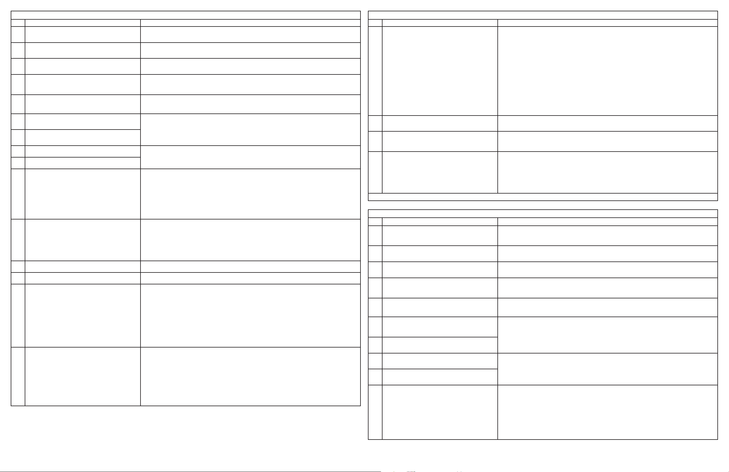
Electronic Oven Control (EOC) Fault Code Descriptions
Code Condition / Cause Suggested Corrective Action
F10 The oven control has sensed a potential runaway condition in the
lower oven. The Appliance Control Board may have a shorted relay,
RTD sensor may have gone bad.
F11 Shorted keypad: key has been detected as pressed for a long period
and is triggering a shorted key alarm, terminating all oven activity.
F13 Incorrect EEPROM checksum: the control (User Interface Board or
Appliance Control Board) internal memory maybe have become
corrupted.
F14 Misconnected at cable. The User Interface Board does not see the
glass touch panel as being well connected (4 at cables).
F15 Controller self check failed. The User Interface Board or the Appliance
Control Board has detected a problem with its internal circuit.
F20 Communication problem between the User Interface Board and the
Appliance Control Board: the User Interface Board is not able to initiate
communication with the Appliance control board.
F21 Communication problem between the User Interface Board and the
Appliance Control Board: the User Interface Board is no longer able to
detect communication from the Appliance control board.
F30 Open RTD sensor probe/ wiring problem: the Appliance Control board
sees the lower oven temperature probe as being an open circuit.
F31 Shorted RTD sensor probe/ wiring problem: the Appliance Control
board sees the lower oven temperature probe as being a short circuit.
F43 The microwave «external» cooling fan speed (as read by the
tachometer input of the Appliance Control Board) is abnormally slow
F44 The microwave «external» cooling fan speed (as read by the
tachometer input of the Appliance Control Board) is abnormally high
F61 Loss of zero-cross synchronization signal at the ACB Verify the appliance control board (ACB) is connected to L1 on connector J1 pin 1 and to neutral on connector J1 pin 2.
F62 Loss of the zero-cross synchronization signal at the user interface
board.
F80 Communication problem between the User Interface Board and the
Microwave Control Board: the User Interface Board is not able to
initiate communication with the Microwave Control Board.
F81 Damper Error. The Microwave Control Board reports that it is not able
to detect the proper position of the damper.
If oven is overheating, disconnect power. Check RTD sensor probe and replace if necessary.
If oven continues to overheat when power is reapplied, replace Appliance Control Board.
If problem persists replace the User Interface Board.
If a key was pressed inadvertently for a long time the fault code should go away once the key is released.
If the fault code cannot be cleared the touch panel is most likely defective (replace touch panel).
If changing the touch panel did not x the problem replace the User Interface Board.
Disconnect power, wait 30 seconds and reapply power. If fault returns upon power-up, replace the Appliance Control Board.
If problem persists replace the User Interface Board.
Check the 4 at cables connections between the User Interface Board (J4, J6, J8, J9) and the touch panel. Make sure the cables are fully inserted
into the connectors. Check for bent pins and verify cable integrity.
If all 4 cables appear to be good replace the User Interface Board.
If the problem persists replace the touch panel.
Replace the User Interface Board.
If the problem persists replace the touch panel.
If the problem persists replace the Appliance Control Board.
Check the communication harness from connector P20 (pins 1,2,7,9,11) on the Appliance Control Board to connector J2 on the User
Interface Board.
If the problem persists replace the Appliance Control Board.
If the problem persists replace the User Interface Board.
Check wiring in lower oven probe circuit for possible open or short condition
Check RTD resistance at room temperature (compare to probe resistance chart). If resistance does not match the chart, replace the
RTD sensor probe.
Let the oven cool down and restart the function. If the problem persists, replace the Appliance Control Board.
Check if the microwave “external” cooling fan (the one outside of the microwave chassis) is turning. This fan is supposed to be active
anytime the microwave is used and is expected to remain ON for a few minutes after the microwave has stopped. A fan not turning at
all or a fan abnormally slow will trigger an F43 fault code
Check the connection to the cooling fan speed sensor from P19 on the appliance control board to the sensor located on the fan.
If the fan is not turning or turns very slowly check the 120VAC voltage on the fan. If 120VAC is present at the fan but the fan does not
physically turn replace the fan. If 120VAC is not present check the wiring from the Appliance Control Board (is there 120VAC on P16?
Is the fan correctly connected between P15 and Neutral?).
If the cooling fan appears to turn normally but an F43 fault code is generated it means there is a problem with the reading of the fan
speed sensor. Make sure the connection to the fan sensor is properly made and make sure it is connected to connector P19 on the
Appliance Control Board. Make sure the wires in this harness go to the right connector pins. If the wiring is good replace the cooling
fan. If the problem persists replace the Appliance Control Board.
Visually inspect the microwave «external» cooling fan (the one outside of the microwave chassis). This fan is supposed to be active
anytime the microwave is used and is expected to remain ON for a few minutes after the microwave has stopped. A fan turning
abnormally fast will trigger an F44 fault code. Verify the mechanical construction of the fan.
Verify there is nothing blocking the air ow of the fan (that would make the fan turn faster).
Check the 120VAC voltage on the fan. A voltage higher than 120VAC + 10% could make it go too fast.
If the cooling fan appears to turn normally but an F44 fault code is generated there could be a problem with the reading of the fan speed
sensor. Make sure the connection to the fan sensor is properly made and make sure it is connected to connector P19 on the Appliance
Control Board. Make sure the wires in this harness go to the right connector pins. If the wiring is good replace the cooling fan. If the
problem persists replace the Appliance Control Board.
If the line and neutral connector is good and problem persist replace the ACB.
Verify the zero-cross signal from ACB connector P20 pin 3 is properly connected to the user interface board on connector J1 pin 3.
If the problem persist replace the user interface board.
Verify if the microwave is powered (120VAC) by doing this simple test: Open the microwave door and check if the microwave light
(inside the cavity) turns ON or not. If it does not turn ON it means the microwave and it’s controller have no power and it explains
why the Microwave Control Board is not able to communicate with the User Interface Board. In that event an investigation must
be done to nd out why it has not power: it could be a fuse opened (fuse external to the microwave chassis or fuse internal to
the microwave chassis). A fuse could be opened due to an over-current or a microwave door switch problem (see door switch
adjustment section).
If the F80 error occurred while the oven was hot there is a possibility the fault code was caused be a microwave thermal cut-out that
opened. Verify nothing is blocking the air owing out of the microwave and verify cooling fans (internal and external) are working.
Note that a thermal cut-out will close once the unit cools down. A continuity check across the thermal cut-out terminals can be done.
Refer to the thermal cut-out section.
If the microwave appears to be powered (fuses and thermal cut-outs ok) but there is still no communication between the User Interface
Board and the Microwave Control Board verify the wire harness that connects the two boards, from J3 on the User Interface Board to
connector «D» on the Microwave Control Board. If the harness is good there could be a problem with the User Interface board. Try
replacing it. If the problem persists replace the Microwave Control Board.
Expected operation: when the micro-combi unit is plugged in, the damper motor operates (relay RY4) until the damper is opened and the
damper switch closes. Then the damper motor stops operation.
If the Microwave Control Board is not reading the position of the damper as opened, the F81 error will also be generated when using
microwaves functions (non-convection).
When a convection function is started the Microwave Control Board attempts to move the damper to the closed position by energizing the
damper motor and reading the damper switch. If after 59 seconds it has not seen the closed position the microwave stops and the F81
fault code is generated.
If the damper motor does not turn, verify it is getting 120VAC from the Microwave Control Board. If 120VAC is present but the motor still
does not turn replace the motor. If 120VAC is not present check the wire harness and the Microwave Control Board.
If the damper motor is good check the damper switch. When switch actuator is pushed by the damper motor cam, a meter should indicate
a closed circuit. When power cord is plugged into the wall receptacle, the damper motor operates and damper cam will start to rotate.
When the switch actuator is released, a meter should be indicating an open circuit. If improper operation is indicated, replace the
damper switch.
Electronic Oven Control (EOC) Fault Code Descriptions
Code Condition / Cause Suggested Corrective Action
F82 Microwave thermistor open error. The microwave control is not able to
read correctly the temperature in the microwave cavity, or there is no
heat generated by the convection element.
F83 Fire detected in microwave oven By sensing sudden changes of the microwave thermistor value the Microwave Control Board can detect a re in the microwave cavity.
F84 Communication problem between the User Interface Board and
the Microwave Control Board: the User Interface Board lost
communication with the Microwave Control Board (loss of microwave
communication «heart beat»).
F90 Motor Door Latch mechanism failure. The oven control has not been
able to lock or unlock the lower oven door successfully.
Note: Generally speaking, F1X implies a control failure, F3X an oven probe problem, and F9x a latch motor problem.
CODES D’ERREUR POUR LA FICHE TECHNIQUE DE LA CUISINIÈRE AVEC BOUTONS DE COMMANDE À L’AVANT
Code Description de l’erreur
F10 Le contrôle de four a détecté une dérive potentielle dans le four
du bas. Il peut s’agir d’un relais court-circuité dans le tableau de
commande de l’appareil ou d’un capteur de température dont la
résistance est erronée.
F11 Pavé numérique court-circuité : détection d’une touche enfoncée
pendant une longue période, déclenchant une alarme < touche courtcircuitée > et arrêtant toute activité du four.
F13 Erreur de somme de contrôle d’EEPROM : la mémoire intégrée (module
d’interface utilisateur ou tableau de commande de l’appareil) est
possiblement corrompue.
F14 Câble plat mal branché. Le module d’interface utilisateur détecte un
mauvais branchement de l’écran tactile (4 câbles plats).
F15 Échec d’autovalidation du contrôleur. Le module d’interface utilisateur
ou le tableau de commande de l’appareil a détecté un problème
interne.
F20 Problème de communication entre le module d’interface utilisateur et
le tableau de commande de l’appareil : le module d’interface utilisateur
est incapable d’établir la communication avec le tableau de commande
de l’appareil.
F21 Problème de communication entre le module d’interface utilisateur et
le tableau de commande de l’appareil : le module d’interface utilisateur
n’établit plus la communication avec le tableau de commande de l’appareil.
F30 Sonde du capteur de température à résistance ou câblage ouvert : le
tableau de commande de l’appareil voit la sonde de température de
four inférieur comme un circuit ouvert.
F31 Sonde du capteur de température à résistance ou câblage court-
circuité : le tableau de commande de l’appareil voit la sonde de
température de four inférieur comme un court-circuit.
F43 La vitesse du ventilateur « externe » du four à micro-ondes (lue par le
tachymètre du tableau de commande de l’appareil) est anormalement
lente.
The fault code could have been generated because the convection element is not heating. In that case the microwave operation stops
after approximately 4 minutes and 15 seconds and generates the F82 fault code. Verify the operation of the microwave convection
element. Start a convection function (ex: Conv Bake 350F for 10 minutes), wait a few minutes. Check if you see the temperature
rising or not in the unit’s display. You can also try to touch the left side wall in the microwave cavity (where the convection element is
located) to see if the element is heating or not, but take care not to burn yourself. The convection element can also be tested using
this procedure: Disconnect power supply cord, and remove outer case. Open the door and block it open. Discharge high voltage
capacitor. Make sure the heating element is fully cooled and test as follows: Disconnect wire leads and measure the resistance with
an ohmmeter. The resistance between the heating element terminals should be approximately 10.2ohm. Disconnect wire leads and
measure the insulation resistance with 500V - 100Mohm insulation resistance meter. The insulation resistance between heating
element terminal and cavity should be more than 0.5Mohm. Reconnect all leads removed from components. Reinstall the outer case
(cabinet).
Another possible root cause for the convection element not heating could be a door switch problem. If the 3rd door switch is not closed
whole the door is closed the convection element will not heat. Refer to the microwave door switches section.
If the convection element is good the problem could come from the microwave thermistor. The thermistor can be tested following
this procedure: disconnect power supply cord, and remove outer case. Open the door and block it open. Discharge high voltage
capacitor. Disconnect connector-E from the microwave controller. Measure the resistance of the thermistor with an ohmmeter by
connecting the ohmmeter leads to connector «E» Pin 3 and 4. At room temperature (68°F(20°C) - 86°F(30°C) the resistance should
be approx. 350k - 155K. If the meter does not indicate a resistance within this range replace the thermistor. Reconnect all leads
removed from components during testing. Reinstall the outer case (cabinet). Reconnect power supply cord after the outer case is
installed. Run oven and check all functions.
In that event it terminates all microwave activity and generate an F83 fault code. Clear the condition that possibly created a re in the
cavity and test the microwave again.
See F80.
Turn off power for 30 seconds, then turn on power. Try again to make the door lock or unlock (ex: initiate a Lockout or a Clean cycle).
Check if the Lock Motor is turning or not. If it is not then check if there is 120VAC at the motor when it is expected to turn to see if the
failure originates from a bad motor (120VAC present but not turning) or a problem with the relay board (J1 pin 4 on Appliance Control
Board is the output to the Lock Motor). The Lock Motor can also be tested by applying 120VAC directly to the motor (unplug it from
the Appliance Control Board rst). Replace the Lock Motor or Appliance Control Board if necessary.
If the Lock Motor is turning but the oven control cannot nd the locked or unlocked position (ex: motor turns continuously until F90 fault
code is generated) the Lock Switch needs to be veried. Check wiring to the Appliance Control Board. Verify with ohmmeter if the
switch makes contact properly. If the Lock Switch is defective replace the Motor Lock Assembly.
If all above steps failed to correct the situation, replace the Appliance Control Board.
Action corrective suggérée
Si le four surchauffe, débrancher l’alimentation. Vérier la sonde de capteur de température à résistance et la remplacer le cas échéant.
Si le four continue à surchauffer après la remise en marche, remplacer le tableau de commande de l’appareil.
Si le problème persiste, remplacer le module d’interface utilisateur.
Si une touche demeure enfoncée par inadvertance, le code d’erreur doit disparaître une fois la touche relâchée.
Si le code d’erreur ne disparaît pas, l’écran tactile est le plus susceptible d’être défectueux (remplacer l’écran tactile).
Si le remplacement de l’écran tactile ne règle pas le problème, remplacer le module d’interface utilisateur.
Débrancher l’alimentation, attendre 30 secondes, puis redémarrer. Si la panne réapparaît à la mise sous tension, remplacer le tableau
de commande de l’appareil.
Si le problème persiste, remplacer le module d’interface utilisateur.
Vérier les 4 branchements des câbles plats entre le module d’interface utilisateur (J4, J6, J8, J9) et l’écran tactile. S’assurer que les câbles plats sont
bien insérés dans les connecteurs. Chercher d’éventuelles broches tordues et vérier l’intégrité des câbles.
Si les 4 câbles semblent en bon état, remplacer le module d’interface utilisateur.
Si le problème persiste, remplacer l’écran tactile.
Remplacer le module d’interface utilisateur.
Si le problème persiste, remplacer l’écran tactile.
Si le problème persiste, remplacer le tableau de commande de l’appareil.
Vérier le faisceau de communication de la che P20 (broches 1, 2, 7, 9 et 11) du tableau de commande de l’appareil à la prise J2 du
module d’interface utilisateur.
Si le problème persiste, remplacer le tableau de commande de l’appareil.
Si le problème persiste, remplacer le module d’interface utilisateur.
Chercher un court-circuit ou un circuit ouvert dans l’installation électrique du circuit de sonde du four inférieur
Vérier le capteur de température à résistance à la température ambiante (comparer au graphique de résistance de la sonde). Si la
résistance n’égale pas le graphique, remplacer la sonde de capteur de température à résistance.
Laisser refroidir le four et relancer la fonction. Si le problème persiste, remplacer le tableau de commande de l’appareil.
Vérier si le ventilateur « externe » (situé hors du châssis) du four à micro-ondes tourne. Ce ventilateur est censé être en marche chaque
fois que le four à micro-ondes est utilisé et doit demeurer EN MARCHE pendant quelques minutes après l’arrêt du four à micro-ondes. Un
ventilateur qui ne tourne pas ou un ventilateur anormalement lent génère le code d’erreur F43
Vérier la connexion au capteur de vitesse du ventilateur de P19 sur le tableau de commande d’appareil au capteur localisé sur le
ventilateur.
Si le ventilateur ne tourne pas ou tourne très lentement, vérier la tension de 120 V CA du ventilateur. Si elle est présente, mais le ventilateur ne tourne pas, remplacer le ventilateur. Si elle est absente, vérier le câblage du tableau de commande de l’appareil (la tension de
120 V CA est-elle présente à la che P16? Le ventilateur est-il correctement branché entre la che P15 et le neutre?)
Si le ventilateur semble tourner normalement, mais qu’un code d’erreur F43 est généré, cela indique une anomalie de lecture du capteur
de vitesse du ventilateur. Valider la connexion du capteur de ventilateur et s’assurer qu’il est branché à la prise P19 du tableau de commande de l’appareil. S’assurer que les ls du faisceau sont raccordés aux bonnes broches du connecteur. Si le câblage est en bon état,
remplacer le ventilateur. Si le problème persiste, remplacer le tableau de commande de l’appareil.
Page 3

P20 À J7 COMMANDE DU FOUR/MINITERIE
3-DOOR SWITCH/INTERRUPTEUR DE PORTE
DLB OUT/DLB-LIGNE DOUBLE INTERROMPUE SORTIE
CODES D’ERREUR POUR LA FICHE TECHNIQUE DE LA CUISINIÈRE AVEC BOUTONS DE COMMANDE À L’AVANT
Code Description de l’erreur
F44 La vitesse du ventilateur « externe » du four à micro-ondes (comme
lue par le tachymètre du tableau de commande de l’appareil) est
anormalement grande.
F61 Perte de signal de synchronisation au passage par zéro du TCA. Valider que le tableau de commande de l’appareil (TCA) est raccordé à L1, broche 1 de la prise J1 au neutre broche 2 de la prise J1.
F62 Perte du signal de synchronisation au passage par zéro du module
d’interface utilisateur.
F80 Problème de communication entre le module d’interface utilisateur
et le tableau de commande de l’appareil : le module d’interface
utilisateur est incapable d’établir la communication avec le tableau de
commande du four à micro-ondes.
F81 Erreur de registre. Le tableau de commande du four à micro-ondes
signale être incapable de détecter la position exacte du registre.
F82 Erreur de thermistance ouverte. Le tableau de commande du four
à micro-ondes est incapable de lire correctement la température
intérieure de la cavité ou l’élément à convection ne produit aucune
chaleur.
F83 Incendie à l’intérieur du four à micro-ondes. Le tableau de commande peut détecter un incendie dans la cavité du four à micro-ondes en notant des changements soudains de la
F84 Problème de communication entre le module d’interface utilisateur et
le tableau de commande du four à micro-ondes : le module d’interface
utilisateur est incapable d’établir la communication avec le tableau de
commande du four à micro-ondes (perte de communication «rythme»
du four à micro-ondes).
F90 Échec du moteur du mécanisme de loquet de porte. Le contrôle de
four n’a pas pu verrouiller ou déverrouiller la porte du four inférieur.
Remarque : En général, F1X implique un échec de contrôle, F3X un problème de sonde de four et F9X un problème de moteur de verrouillage.
Faire une inspection visuelle du ventilateur « externe » (situé hors du châssis) du four à micro-ondes. Ce ventilateur est censé être en
marche chaque fois que le four à micro-ondes est utilisé et doit demeurer EN MARCHE pendant quelques minutes après l’arrêt du four
à micro-ondes. Un ventilateur qui tourne anormalement vite déclenchera un code d’erreur F44. Vérier la construction mécanique du
ventilateur.
Valider que rien ne bloque le ux d’air du ventilateur (le ventilateur tourne plus rapidement).
Vérier la tension de 120 V CA du ventilateur. Une tension de 10 % plus élevée que 120 V CA peut le faire tourner trop rapidement.
Si le ventilateur semble tourner normalement, mais qu’un code d’erreur F44 est généré, cela indique une anomalie de lecture du capteur
de vitesse du ventilateur. Valider la connexion du capteur de ventilateur et s’assurer qu’il est branché à la che P19 du tableau de commande de l’appareil. Assurer que les ls du faisceau sont raccordés aux bonnes broches du connecteur. Si le câblage est en bon état,
remplacer le ventilateur. Si le problème persiste, remplacer le tableau de commande de l’appareil.
Si la connexion de la ligne et du neutre au connecteur est bonne et que le problème persiste, remplacer le TCA.
Vérier que le signal de passage par zéro à la broche 3 de la che P20 du TCA est convenablement raccordé au module d’interface
utilisateur à la broche 3 de la prise J1.
Si le problème persiste, remplacer le module d’interface utilisateur.
Assurer que le four à micro-ondes est alimenté (120 V CA) en faisant cet essai simple : Ouvrir la porte du four à micro-ondes et valider
que la lumière (à l’intérieur) s’allume ou pas. Si elle ne s’allume pas, cela signie que le four à micro-ondes et son contrôleur ne sont
pas alimentés; cela explique pourquoi le tableau de commande du four à micro-ondes est incapable de communiquer avec le module
d’interface utilisateur. Le cas échéant, chercher à découvrir pourquoi il n’y a pas d’alimentation : il peut s’agir d’un fusible ouvert (externe
au châssis ou interne au châssis du four à micro-ondes). Un fusible peut être ouvert en raison d’une surtension ou d’un problème de
commutateur de porte du four à micro-ondes (voir la section Réglage du commutateur de porte).
Si un code d’erreur F80 apparaît pendant que le four est chaud, il est possible qu’il soit généré par l’ouverture d’un dispositif de
protection thermique. Assurer que rien ne bloque le ux d’air s’écoulant du four à micro-ondes et valider que les ventilateurs (interne et
externe) sont en marche. À noter que le dispositif de protection thermique se referme une fois l’appareil refroidi. Un contrôle de continuité peut être fait aux bornes du dispositif de protection thermique. Se rapporter à la section Dispositifs de protection thermique
Si le four à micro-ondes semble être alimenté (fusibles et dispositifs de protection thermique en bonne condition), mais qu’il n’y a toujours pas de communication entre le module d’interface utilisateur et le tableau de commande du four à micro-ondes, vérier le faisceau
de câblage qui connecte les deux modules, de J3 du module d’interface utilisateur au connecteur « D » du tableau de commande du
four à micro-ondes. Si le faisceau est en bon état, le module d’interface utilisateur peut poser problème. Tenter de le remplacer. Si le
problème persiste, remplacer le tableau de commande du four à micro-ondes.
Fonctionnement prévu : quand l’unité microcombinée est raccordée, le moteur du registre fonctionne (relais RY4) jusqu’à ce que le registre
s’ouvre et que son commutateur se referme. Le moteur de registre s’arrête.
Si le tableau de commande du four à micro-ondes ne lit pas la position ouverte du registre, un code d’erreur F81 est généré pendant
l’utilisation du four à micro-ondes (non à convection).
Au lancement d’une fonction à convection, le tableau de commande du four à micro-ondes tente de refermer le registre en activant le
moteur et en lisant le commutateur. S’il n’a pas détecté la position fermée après de 59 secondes, le four à micro-ondes s’arrête et un code
d’erreur F81 est généré.
Si le moteur de registre ne tourne pas, valider qu’il reçoit la tension de 120 V CA du tableau de commande du four à micro-ondes. Si la
tension 120 V CA est présente, mais le moteur ne tourne toujours pas, remplacer le moteur. Si la tension 120 V CA est absente, vérier le
faisceau de câblage et le tableau de commande du four à micro-ondes.
Si le moteur de registre est en bon état, vérier le commutateur de registre. Quand l’actionneur de commutateur est poussé par la came
du moteur de registre, un cadran indique un circuit fermé. Quand le cordon d’alimentation est branché sur la prise murale, le moteur de
registre se met en marche et la came commence à tourner. Quand l’actionneur de commutateur est déclenché, un cadran indique un circuit
ouvert. Si un fonctionnement défectueux est reconnu, remplacer le commutateur de registre.
Un code d’erreur doit être généré puisque l’élément de convection ne chauffe pas. Dans ce cas, le four à micro-ondes s’arrête après
environ 4 minutes et 15 secondes et génère un code d’erreur F82. Vérier le fonctionnement de l’élément de convection du four à
micro-ondes. Démarrer une fonction à convection [par exemple : cuisson à convection, 177 °C (350 °F)] pendant 10 minutes), attendre
quelques minutes. Vérier à l’afchage de l’appareil si la température s’élève ou pas. Essayer également de toucher le mur latéral
gauche de la cavité du four (où l’élément de convection est localisé) et voir si l’élément chauffe ou pas, mais veiller à ne pas se brûler.
L’élément à convection peut également être mis à l’essai à l’aide de cette procédure : Débrancher le cordon d’alimentation et enlever
l’enveloppe extérieure. Ouvrir la porte et la bloquer. Décharger le condensateur à haute tension. S’assurer que l’élément chauffant est
complètement refroidi et essayer comme suit : Débrancher les ls et mesurer la résistance avec un ohmmètre. La résistance entre les
bornes de l’élément chauffant doit lire environ 10,2 Ω. Débrancher les ls et mesurer la résistance d’isolation à l’aide d’un mégohmmètre
de 500V à 100 MΩ. La résistance d’isolation entre la borne d’élément chauffant et la cavité doit être supérieure à 0,5 MΩ. Raccorder à
nouveau tous les ls des composants. Reposer l’enveloppe extérieure (le cabinet).
Un problème de commutateur de porte peut également être une autre raison première pour laquelle l’élément de convection ne chauffe
pas. Si le troisième commutateur de porte n’est pas complètement fermé, l’élément de convection ne chauffe pas. En référer à la section Commutateurs de porte du four à micro-ondes.
Si l’élément de convection est en bon état, le problème peut venir de la thermistance du four à micro-ondes. La procédure qui suit
permet de mettre la thermistance à l’essai : débrancher le cordon d’alimentation et enlever l’enveloppe extérieure. Ouvrir la porte et la
bloquer. Décharger le condensateur à haute tension. Débrancher le connecteur E du contrôleur de four à micro-ondes. Mesurer la résistance de la thermistance avec un ohmmètre en le raccordant aux broches 3 et 4 du connecteur « E ». La résistance doit lire entre 350
et 155 kΩ à température ambiante [20 (68) à 30 °C (86 °F)]. Si la lecture ne se trouve pas dans cette plage, remplacer la thermistance.
Raccorder à nouveau tous les ls des composants. Reposer l’enveloppe extérieure (le cabinet). Rebrancher le cordon d’alimentation
après avoir reposé l’enveloppe extérieure. Mettre le four en marche et vérier toutes les fonctions.
valeur de la thermistance. Dans ce cas, il annule toutes les activités du four à micro-ondes et génère un code d’erreur F83. Éliminer la
condition qui a vraisemblablement provoqué l’incendie dans la cavité et réessayer le four à micro-ondes.
Voir le code d’erreur F80.
Éteindre l’appareil pendant 30 secondes, puis le remettre en marche. Tenter à nouveau de verrouiller ou déverrouiller la porte (par
exemple : lancer un cycle de verrouillage ou de nettoyage).
Vérier si le moteur de verrouillage tourne ou pas. S’il ne tourne pas, vérier si la tension de 120 V CA est présente au moteur quand
il est sensé tourner pour voir si l’anomalie provient d’un mauvais moteur (120 V CA présent, mais ne tourne pas) ou un problème de
module de relais (broche 4, J1 du tableau de commande de l’appareil est la sortie vers le moteur de blocage). Il est également possible
de mettre le moteur à l’essai en appliquant une tension de 120 V CA directement aux bornes du moteur (le débrancher du tableau de
commande de l’appareil en premier lieu). Le cas échéant, remplacer le moteur de verrouillage ou le tableau de commande de l’appareil.
Si le moteur tourne, mais le contrôle du four ne trouve pas la position < verrouillée > ou < déverrouillée > (par exemple : le moteur
tourne continuellement jusqu’à la génération d’un code d’erreur F90), vérier l’interrupteur de blocage. Vérier le câblage du tableau de
commande de l’appareil. Vérier avec l’ohmmètre si le commutateur établit convenablement le contact. Si l’interrupteur de blocage est
défectueux, remplacer le module de serrure motorisée.
Si toutes les étapes ci-dessus échouent, remplacer le tableau de commande de l’appareil.
Action corrective suggérée
RELAY BOARD
PANNEAU DE RELAIS
L1, MICROWAVE FUSE/MICRO-ONDES FUSIBLE
NEUTRAL/NEUTRE
DLB IN/DLB-LIGNE DOUBLE INTERROMPUE ENTRÉE
CONVECTION ELEMENT/ÉLÉMENT DE CONVECTION
BAKE ELEMENT/ÉLÉMENT DE CUISSON
BROIL ELEMENT/ÉLÉMENT DE GRILLAGE
P17
NEUTRAL/NEUTRE-3
L1-1
L1
P6 P7 P8 P9
K2
K4
K5
P12
1
P11
P10
K8
K1
K3 K6 K7
P20 TO J7 OVEN CONTROL/TIMER
CLEAN CATALYST/CATALYSEUR DE NETTOYAGE
LATCH MOTOR/MOTEUR VERROU
COOLING FAN-LOW/VENTILATEUR DE REFROIDISSEMENT-BASSE
COOLING FAN-HIGH/VENTILATEUR DE REFROIDISSEMENT-HAUTE
HALOGEN LAMPS/LAMPE DU FOUR-HALOGENE
CONVECTION FANS/VENTILATUERS DES CONVECTION
J1
Q14
P5
1
Q15
K10
P15-MICROWAVE COOLING FAN (OPT)
P15
VENT DE REFROID-MICRO-ONDE (OPT)
P16
P16-MICROWAVE COOLING FAN (OPT)
VENT DE REFROID-MICRO-ONDE (OPT)
1
P3
P3-TEMP PROBE
SONDE À TEMP
P1
P1-MEAT PROBE (OPT)
SONDE À VIANDE (OPT)
P18
1-LATCH MOTOR/MOTEUR VERROU
7-COMMON/COMMUNE
P19JP1P20
USER INTERFACE BOARD/OVEN CONTROL/TIMER
PANNEAU D’INTERFACE DE L’UTILISATEUR (UIB)/ COMMANDE DU
FOUR/MINUTERIE
J5
J3
J3 TO MICROWAVE/J3 À MICRO-ONDE
J7 TO P20 OVEN RELAY BOARD
J7 À P20 PANNEAU DE RELAIS
J7
J6J8
J1
J9
J4
Page 4

COLOR CODE
CODE DE COULEURS
GY=GREY/GRIS
G =GREEN/VERT
W =WHITE/BLANC
R =RED/ROUGE
O =ORANGE
Y =YELLOW/JAUNE
BR=BROWN/BRUN
BL=BLUE/BLEU
BK=BLACK/NOIR
V = VIOLET
T =TAN/OCRE
P =PINK/ROSE
PR=PURPLE/POURPRE
CAUTION:
DISCONNECT POWER BEFORE SERVICING UNIT.
LABEL ALL WIRES PRIOR TO DISCONNECTION WHEN SERVICING CONTROLS.
WIRING ERRORS CAN CAUSE IMPROPER AND DANGEROUS OPERATION.
VERIFY PROPER OPERATION AFTER SERVICING.
ATTENTION:
DÉBRANCHEZ L'APPAREIL AVANT DE PROCÉDER À LA RÉPARATION.
IDENTIFIEZ TOUS LES FILS AVANT DE LES DÉBRANCHER LORSQUE VOUS PROCÉDEZ À UNE RÉPARATION.
UNE ERREUR DE FILAGE PEUT CAUSER UN FONCTIONNEMENT INADÉQUAT ET/OU UNE SITUATION DANGEREUSE.
VÉRIFIEZ QUE L'APPAREIL FONCTIONNE CORRECTEMENT APRÈS LA RÉPARATION.
INDIQUE FONCTIONNALITÉS OPTIONNELLES
INDICATES OPTIONAL FEATURES
FOUR ENCASTRÉ ÉLECTRIQUE/MICRO-ONDES
WALL OVEN/MICROWAVE COMBINATION
PANNEAU DE RELAIS
MINITERIE MICRO-ONDE
MICRO-ONDE FUSIBLE
MOTEUR VERROU
INTERRUPTEUR DE PORTE
ÉLÉMENT DE CONVECTION
ÉLÉMENT DE CUISSON
ÉLÉMENT DE GRILLAGE
MICRO-ONDE VENT.R DE REFROID
MICRO-ONDE CAPTEUR DE VITESSE
SONDE À TEMP
SONDE À VIANDE
VENTS. DES CONV.
LAMPES-HALOGENE
VENT. MICRO-ONDE
BASSE VITESSE
HAUTE VITESSE
CATALYSEUR AUTO-NETTOYAGE
DISJONCTEUR
THERMIQUE
BASSE VITESSE
HAUTE VITESSE
VENT. DE REFROID.
MOTEUR VERROU
“FRESH CLEAN”/”AIR GUARD”
CLEAN CATALYST
MICROWAVE SCHEMATIC DIAGRAM / MICRO-ONDES DIAGRAMME SCHÉMATIQUE
NOTE: CONDITION OF OVEN/NOTE: CONDITION DE FOUR
1. DOOR CLOSED/PORTE FERMÉE
SCHEMATIC/SCHÉMATIQUE
2. CLOCK APPEARS ON DISPLAY/HORLOGE APPARAÎT SUR L'AFFICHAGE
SCHEMATIC DIAGRAM (DOOR CLOSED,COOK OFF CONDITION)
NOISE FILTER UNIT
UNITÉ DE FILTRE DE BRUIT
FUSE
DUMMY
FAUX FUSIBLEBOBINE DE SUPRESSION FANOISE
NOISE SUPPRESSION COIL
120V
60Hz
F AC250V
0.22
F AC125V
RED・PNK
ROSE-ROUGE
0.0033
TTM
*
F AC125V
0.0033
MOTEUR DU PLATEAU TOURN.
OVEN LAMP
LAMPE DU FOUR
TURNTABLE MOTOR
3RD
DOOR
SWITCH
3ÈME INTERRUPTEUR DE PORTE
NOTE: 1.
CIRCUITS SUBJECT TO CHANGE WITHOUT NOTICE
WIRE COLOR CODESARE APPLICABLE TO PRIMARY CIRCUIT ONLY AND NOT
2.
APPLICABLE TO LOW VOLTAGE CIRCUIT AND SECONDARY CIRCUIT.
HOT WIRE(S) MUST BE CONNECTED TO THETERMINAL WITH BLUE MARK
*3.
ON THE LAMP SOCKET AND "H" MARK ON THE POWER SUPPLY CORD.
Figure O-1. Upper Oven Schematic-OFF Condition
DIAGRAMME SCHÉMATIQUE (PORTE FERMÉE, CUIRE OFF ÉTAT)
CONV.
THERMAL
POURPRE
PPL
BRN
BRUN
CUT-OUT
ORG
L.V.
TRANSFORMER
LV TRANSFORMATEUR
CONV. DISJONCTEUR THERMIQUE
ROSE
PNK
CM
DMFMOL
MOTEUR DE CONVECTION
DAMPER MOTOR
MOTEUR AMORTISSEUR
CONVECTION MOTOR
MOTEUR DE VENTILATEUR
FAN MOTOR
DE DÉTECTION
C/T
C/T
FUSIBLE
FUSE
B1
B2
B3
B4
B5
RY4RY5 RY6
B6
B8
B10
A1
UNITÉ DE COMMANDE
E1 E2 E3 E4 E5 F3
INTERR
DOOR
SENSING
DE PORTE
SWITCH
OVEN
THERMAL
CUT-OUT
FOUR DISJONCTEUR THERMIQUE
A7A9
A5 (RY1)
CONTROL
UNIT
RY2RY3
E6
DAMPER
THER-
SWITCH
MISTOR
THERMISTANCE INTERR. AMORTISSEUR
REMARQUE:
1. CIRCUITS SUSCEPTIBLES D'ÊTRE MODIFIÉES SANS PRÉAVIS
2. DES CODES DE COULEUR DE FIL SONT APPLICABLES À CIRCUIT PRIMAIRE ET NE SONT PAS
APPLICABLES À CIRCUIT À BASSE TENSION ET LE CIRCUIT SECONDAIRE.
3. FILS CHAUDS DOIVENT ÊTRE CONNECTER À LA BORNE AVEC LA MARQUE BLEUE SUR LA DOUILLE DE
LAMPE ET LE "H" MARQUE SUR LE CORDON D'ALIMENTATION.
A3
AH SENSOR
AH CAPTEUR
SUPÉRIEURE SCHÉMATIQUE FOUR - CONDITION DE HORS
INTERRUPTEUR DE
VERROUILLAGE PRIMAIRE
PRIMARY INTERLOCK SWITCH
MONITOR SWITCH
ELEMENT
HEATING
ELEMENT DE
CHAUFFAGE
RY1
SECONDARY
INTERLOCK
RELAY
RELAIS DE
SYNCHRONISATION
SECONDAIRE
F2 F1
(RY1)
(RY3)
(RY2)
(RY2)
(RY3)
COMMUTATEUR MONITOR
POWER
TRANSFORMER
TRANSFORMATEUR DE PUISSANCE
CAPACITOR
0.94
CONDENSATEUR
H.V.
RECTIFIER
HV REDRESSEUR
MAGNETRON
MAGNÉTRON
SCHEMATIC/SCHÉMATIQUE
NOTE: CONDITION OF OVEN/NOTE: CONDITION DE FOUR
DOOR CLOSED/PORTE FERMÉE
1. .
2. COOKING TIME PROGRAMMED/TEMPS DE CUISSON PROGRAMMÉ
3. “START” PAD TOUCHED/"START" PAD TOUCHÉ
SCHEMATIC DIAGRAM (DOOR CLOSED,COOK ON CONDITION)
NOISE FILTER UNIT
UNITÉ DE FILTRE DE BRUIT
FUSE
DUMMY
FAUX FUSIBLEBOBINE DE SUPRESSION FANOISE
F AC250V
0.22
F AC125V
0.0033
*
NOISE SUPPRESSION COIL
F AC125V
0.0033
OVEN LAMP
LAMPE DU FOUR
120V
60Hz
3RD
DOOR
SWITCH
3ÈME INTERRUPTEUR DE PORTE
NOTE: 1.
2.
*3.
Figure O-2. Upper Oven Schematic-Microwave Cooking Condition
DIAGRAMME SCHÉMATIQUE (PORTE FERMÉE, CUISINIER À LA CONDITION)
CONV.
THERMAL
POURPRE
PPL
CM
BRN
BRUN
CUT-OUT
ORG
L.V.
TRANSFORMER
LV TRANSFORMATEUR
CONV. DISJONCTEUR THERMIQUEFOUR DISJONCTEUR THERMIQUE
ROSE
RED・PNK
PNK
ROSE-ROUGE
TTM
DMFMOL
MOTEUR DE CONVECTION
MOTEUR DU PLATEAU TOURN.
DAMPER MOTOR
MOTEUR AMORTISSEUR
FAN MOTOR
TURNTABLE MOTOR
MOTEUR DE VENTILATEUR
CONVECTION MOTOR
DE DÉTECTION
CIRCUITS SUBJECT TO CHANGE WITHOUT NOTICE
WIRE COLOR CODESARE APPLICABLE TO PRIMARY CIRCUIT ONLY AND NOT
APPLICABLE TO LOW VOLTAGE CIRCUIT AND SECONDARY CIRCUIT.
HOT WIRE(S) MUST BE CONNECTED TO THE TERMINAL WITH BLUE MARK
ON THE LAMP SOCKET AND "H" MARK ON THE POWER SUPPLY CORD.
C/T
FUSE
INTERR
DE PORTE
C/T
FUSIBLE
A7A9
B1
B2
B3
B8
B10
B4
B5
B6
A1
RY4RY5 RY6
CONTROL
UNIT
UNITÉ DE COMMANDE
E1 E2 E3 E4 E5 F3
DOOR
SENSING
SWITCH
THERMISTOR
THERMISTANCE INTERR. AMORTISSEUR
SUPÉRIEURE SCHÉMATIQUE FOUR - MICRO-ONDES DE CUISSON ÉTAT
OVEN
THERMAL
CUT-OUT
A5 (RY1)
A3
SECONDARY
INTERLOCK
RELAY
RELAIS DE
SYNCHRONISATION
RY2RY3
SECONDAIRE
F2 F1
E6
AH SENSOR
DAMPER
AH CAPTEUR
SWITCH
REMARQUE:
1. CIRCUITS SUSCEPTIBLES D'ÊTRE MODIFIÉES SANS PRÉAVIS
2. DES CODES DE COULEUR DE FIL SONT APPLICABLES À CIRCUIT PRIMAIRE ET NE SONT PAS
APPLICABLES À CIRCUIT À BASSE TENSION ET LE CIRCUIT SECONDAIRE.
3. FILS CHAUDS DOIVENT ÊTRE CONNECTER À LA BORNE AVEC LA MARQUE BLEUE SUR LA DOUILLE DE
LAMPE ET LE "H" MARQUE SUR LE CORDON D'ALIMENTATION.
RY1
(RY1)
(RY3)
(RY2)
(RY2)
(RY3)
INTERRUPTEUR DE
VERROUILLAGE PRIMAIRE
PRIMARY INTERLOCK SWITCH
MONITOR SWITCH
ELEMENT
HEATING
ELEMENT DE
CHAUFFAGE
POWER
TRANSFORMER
TRANSFORMATEUR DE PUISSANCE
CONDENSATEUR
COMMUTATEUR MONITOR
H.V.
RECTIFIER
HV REDRESSEUR
CAPACITOR
0.94
MAGNETRON
MAGNÉTRON
 Loading...