

Electrolux EW27MC65JB1, EW27MC65JB2, EW27MC65JS1, EW27MC65JS2, EW27MC65JS3 Installation Guide
...
United States
iNSTALLATiON AND SERVICEMUST BEPERFORMED BYA QUALiFiED iNSTALLER.
Canada
iMPORTANT: SAVE FOR LOCAL ELECTRICAL iNSPECTOR'S USE.
READ AND SAVE THESE INSTRUCTIONS FOR FUTURE REFERENCE.
FOR YOUR SAFETY: Do not store or use gasoline or other
flammable vapors and liquids in the vicinity of this or any other appliance.
Your new wall oven has been designed to fit a limited variety of cutout sizes to make the job of installing easier.
The first step of your installation should be to measure your current cutout dimensions and compare them to the
cutout dimensions chart below for your model. You may find little or no cabinet work being necessary.
Do not remove spacers (if equipped) on the side walls and/or on the back of the built=in
oven. These spacers center the oven in the space provided. The oven must be centered to prevent excess
heat buildup that may result in heat damage or fire.
*Suggested distance from floor is 111A" (29.2 cm). I
Minimum required distance is 4 1/2"(11.4 cm). _,
43 3/4"
(111.1 cm)
j.
Dooi'Open
(seenote 2).,,
Spacer
2" (5 cm) Wide Wood Spacer
if Needed (seenote 4)
NOTES:
1. Basemust be capable of supporting 275 pounds (125 kg)
for 27" models and 350 pounds (159 kg) for 30" models.
2. Allow at least 21 " (53.3 cm) clearance in front of oven
for door depth when it is open.
3. Dimension G (cutout depth)is critical to the proper
installation of the built-in oven. If the oven decorative
trim does not butt against the cabinet, or if noise is heard
on convection models, verify dimension G to assure it is
according to the required dimension.
PRODUCT DIMENSIONS
MODEL I A I B I C I D
H
3" (7.6 cm)
Max.
Electrical
Junction Box
Figure 1
**4. For a cutout height (H) between 44" (111.8cm)
and 44s/8" (113.3 cm) add a 2" (5 cm) wide wood
shim of appropriate height to each side of the
opening under the appliance side rails. Lifting the
unit will allow you to hide the cutout openings
showing above the unit. The bottom trim of the unit
will hide the shims at the bottom.
**5. For a cutout height (H) between 44s/8'' (113.3 cm)
and 463/8" (117.8 cm) you can order a larger bottom
trim through your Service Center.
27" (68.6 cm) Wall Oven 27 (68.6) 45% (114.9) 24s/8 (62.5) 24V2 (62.2)
30" (76,2 cm) Wall Oven 30 (76.2) 45% (114.9) 281/4 (71.8) 24V2 (62,2)
CUTOUT DIMENSIONS AND CABINET WIDTH
MODEL:. Min: Max,. . Min,
27" (68.6 cm) Wall Oven 25% (65.1) 257/8 (65.7) 23V2 (59.7) 43% (111.3)
30" (76.2 cm) Wall Oven 28V2 (72.4) 29 (73.7) 23V2 (59.7) 43% (111.3)
All dimensionsarein inches(cm).
Printed in United States
Maxi i
44 (111.8) 271/8 (68.9) Min
44 (111.8) 30V8 (76.5) Min
P/N 318201539 (1007) Rev. D
English - pages 1-6
Fran_ais -pages 6-12
important Notes to the Installer
1. Read all instructions contained in these installation
instructions before installing the combination oven.
2. Remove all packing material from the oven
compartments before connecting the electrical supply
to the wall oven.
3. Observe all governing codes and ordinances.
4. Be sure to leave these instructions with the consumer.
5. Oven door may be removed to facilitate installation.
6. THiS COMBINATION OVEN IS NOT APPROVED FOR
STACKABLE OR SIDE-BY=SIDEINSTALLATION.
important Note to the Consumer
Keep these instructions with your Owner's Guide for
future reference. Do not discard oven removal tools found
in the literature bag.
IMPORTANT SAFETY
INSTRUCTIONS
• Be sure your combination oven is installed and
grounded properly by a qualified installer or
service technician.
• This wall oven must be electrically grounded in
accordance with local codes or, in their absence,
with the National Electrical Code ANSI/NFPA
No.70- latest edition in United Sates, or with CSA
Standard C22.1, Canadian Electrical Code, Part 1,
in Canada.
Stepping, leaning or sitting on the
door of this wall oven can result in serious injuries
and can also cause damage to the wall oven.
• Never use your wall oven for warming or heating
the room. Prolonged use of the wall oven without
adequate ventilation can be dangerous.
The electrical power to the oven must
be shut off while line connections are being made.
Failure to do so could result in serious injury or
death,
1. Carpentry
Refer to figure 1 for the dimensions applicable to
your appliance, and the space necessary to receive the
combination oven. The oven support surface may be
solid plywood or similar material, however the surface
must be leveled from side to side and from front to rear.
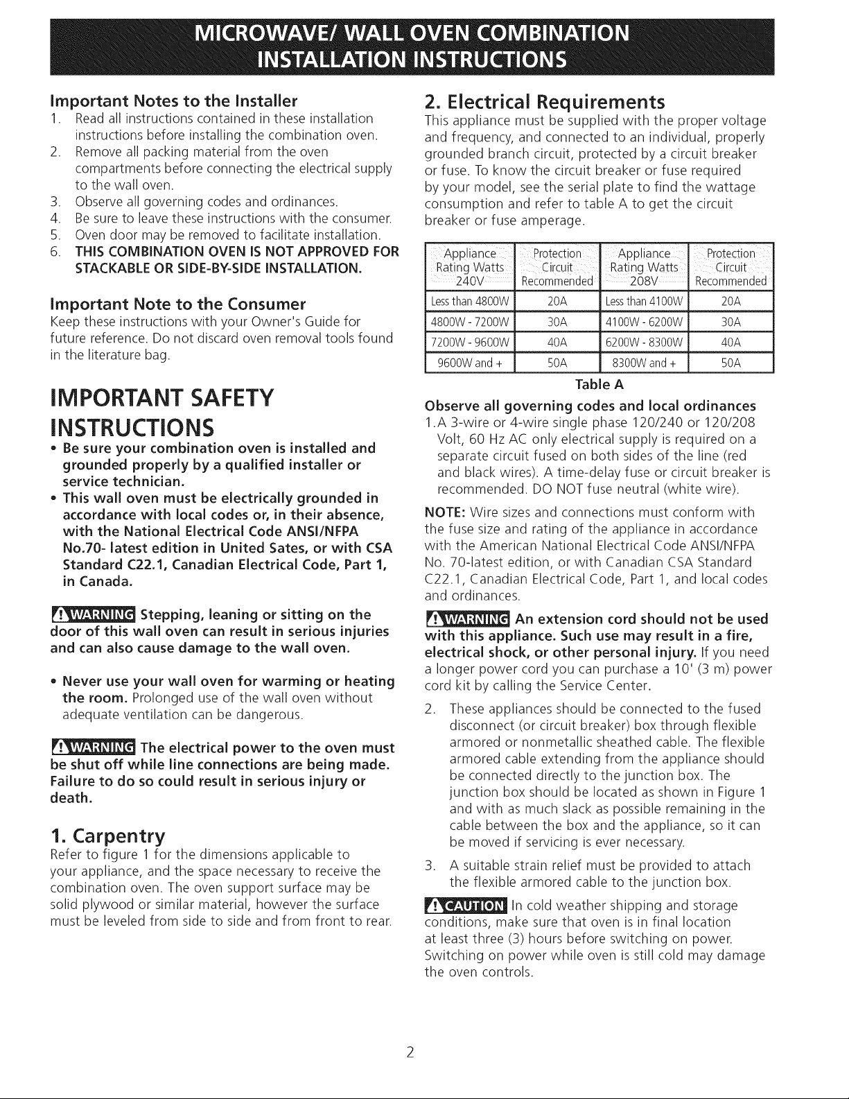
2. Electrical Requirements
This appliance must be supplied with the proper voltage
and frequency, and connected to an individual, properly
grounded branch circuit, protected by a circuit breaker
or fuse. To know the circuit breaker or fuse required
by your model, see the serial plate to find the wattage
consumption and refer to table A to get the circuit
breaker or fuse amperage.
Appliance Protection' Appliance Protection
Rating Watts Circuit Rating Watts Circuit
240V Recommended 208V Recommended
Lessthan4800W 20A Lessthan4100W 20A
4800W- 7200W 30A 4100W- 6200W 30A
7200W- g600W 40A 6200W- 8300W 40A
9600Wand + B0A 8300Wand + B0A
Table A
Observe all governing codes and local ordinances
1.A 3-wire or 4-wire single phase 120/240 or 120/208
Volt, 60 Hz AC only electrical supply is required on a
separate circuit fused on both sides of the line (red
and black wires). A time-delay fuse or circuit breaker is
recommended. DO NOT fuse neutral (white wire).
NOTE: Wire sizes and connections must conform with
the fuse size and rating of the appliance in accordance
with the American National Electrical Code ANSI/NFPA
No. 70-latest edition, or with Canadian CSA Standard
C22.1, Canadian Electrical Code, Part 1, and local codes
and ordinances.
An extension cord should not be used
with this appliance. Such use may result in a fire,
electrical shock, or other personal injury. If you need
a longer power cord you can purchase a 10' (3 m) power
cord kit by calling the Service Center.
2. These appliances should be connected to the fused
disconnect (or circuit breaker) box through flexible
armored or nonmetallic sheathed cable. The flexible
armored cable extending from the appliance should
be connected directly to the junction box. The
junction box should be located as shown in Figure 1
and with as much slack as possible remaining in the
cable between the box and the appliance, so it can
be moved if servicing is ever necessary.
3. A suitable strain relief must be provided to attach
the flexible armored cable to the junction box.
In cold weather shipping and storage
conditions, make sure that oven is in final location
at least three (3) hours before switching on power.
Switching on power while oven is still cold may damage
the oven controls.
2
Electrical Shock Hazard
• Electrical ground is required on this appliance.
• Do not connect to the electrical supply until
appliance is permanently grounded.
• Disconnect power to the junction box before
making the electrical connection.
• This appliance must be connected to a grounded,
metallic, permanent wiring system, or a
grounding connector should be connected to
the grounding terminal or wire lead on the
appliance.
• Do not use a gas supply line for grounding the
appliance.
Failure to do any of the above could result in a
fire, personal injury or electrical shock.
3. Electrical connection
It is the responsibility and obligation of the consumer to
contact a qualified installer to assure that the electrical
installation is adequate and is in conformance with the
National Electrical Code ANSI/NFPA No. 70-latest edition,
or with CSA Standard C22.1, Canadian Electrical Code,
Part 1, and local codes and ordinances.
Risk of electrical shock (Failure to
heed this warning may result in electrocution or
other serious injury.) This appliance is equipped
with copper lead wire. if connection is made to
aluminum house wiring, use only connectors that
are approved for joining copper and aluminum wire
in accordance with the National Electrical Code
and local code and ordinances. When installing
connectors having screws which bear directly on
the steel and/or aluminum flexible conduit, do no
tighten screws sufficiently to damage the flexible
conduit. Do not over bend or excessively distort
flexible conduit to avoid separation of convolutions
en exposure of internal wires.
DO NOT ground to a gas supply pipe. DO NOT connect
to electrical power supply until appliance is permanently
grounded. Connect the ground wire before turning on
the power.
(If your appliance is equipped with a
white neutral conductor.)
This appliance is manufactured with a white neutral
power supply and a frame connected copper wire.
The frame is grounded by connection of grounding
lead to neutral lead at the termination of the
conduit, if used in USA, in a new branch circuit
installation (1996 NEC), mobile home, recreational
vehicles, where local code do not permit grounding
trough the neutral (white) wire or in Canada,
disconnect the white and green lead from each
other and use ground lead to ground unit in
accordance with local codes, connect neutral lead
to branch circuit-neutral conductor in usual manner
see Figure 3. If your appliance is to be connected
to a 3 wire grounded junction box (US only),
where local code permit connecting the appliance-
grounding conductor to the neutral (white) see
Figure 2.
NOTE TO ELECTRICIAN: The armored cable leads
supplied with the appliance are UL-recognized for
connection to larger gauge household wiring. The
insulation of the leads is rated at temperatures much
higher than temperature rating of household wiring. The
current carrying capacity of the conductor is governed by
the temperature rating of the insulation around the wire,
rather than the wire gauge alone.
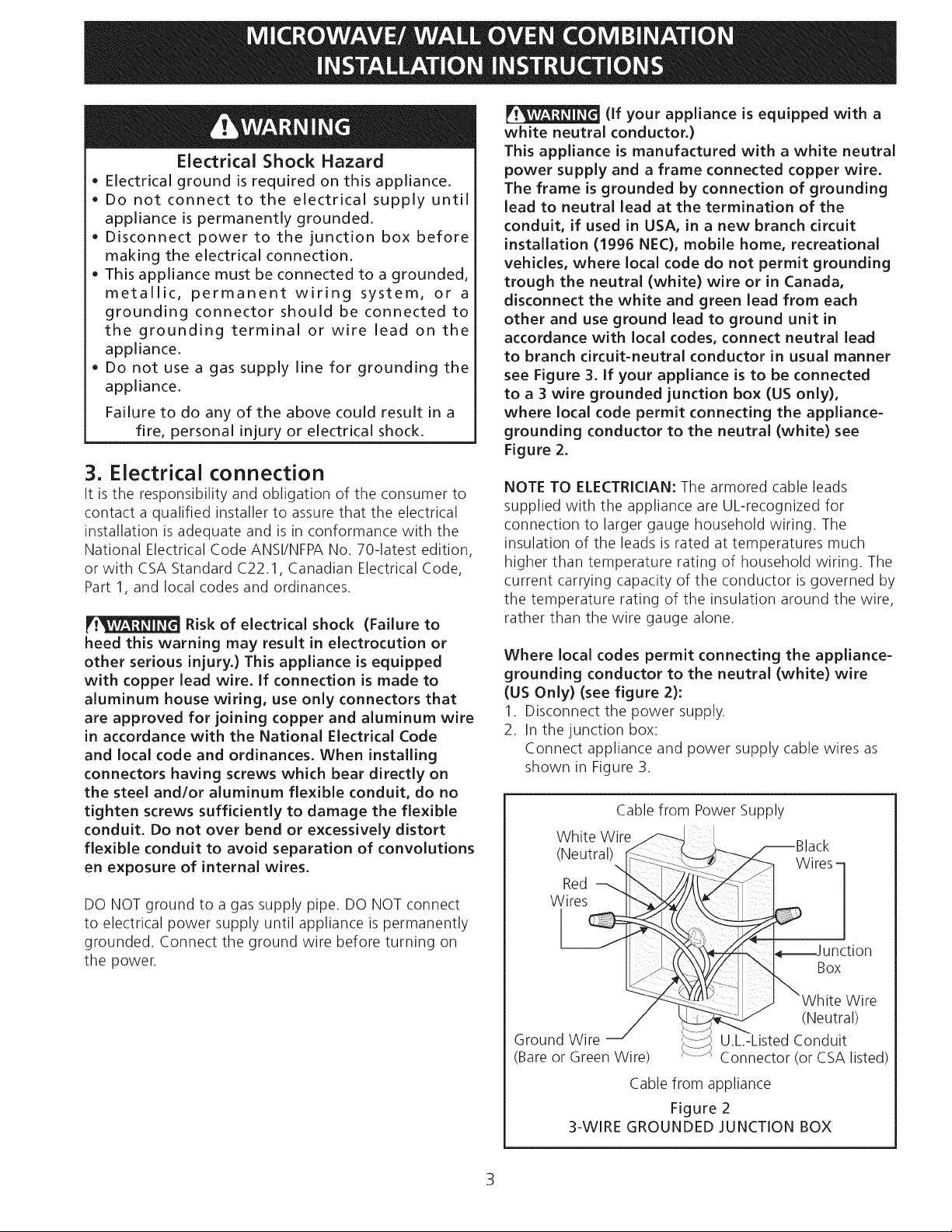
Where local codes permit connecting the appliance-
grounding conductor to the neutral (white) wire
(US Only) (see figure 2):
1. Disconnect the power supply.
2. In the junction box:
Connect appliance and power supply cable wires as
shown in Figure 3.
Cable from Power Supply
White Wire
(Neutral)
Wires-
Red --,
Wires
Box
Ground Wire
(Bare or Green Wire)
3-WIRE GROUNDED JUNCTION BOX
3
Wire
(Neutral)
U.L.-Listed Conduit
Connector (or CSA listed)
Cable from appliance
Figure 2
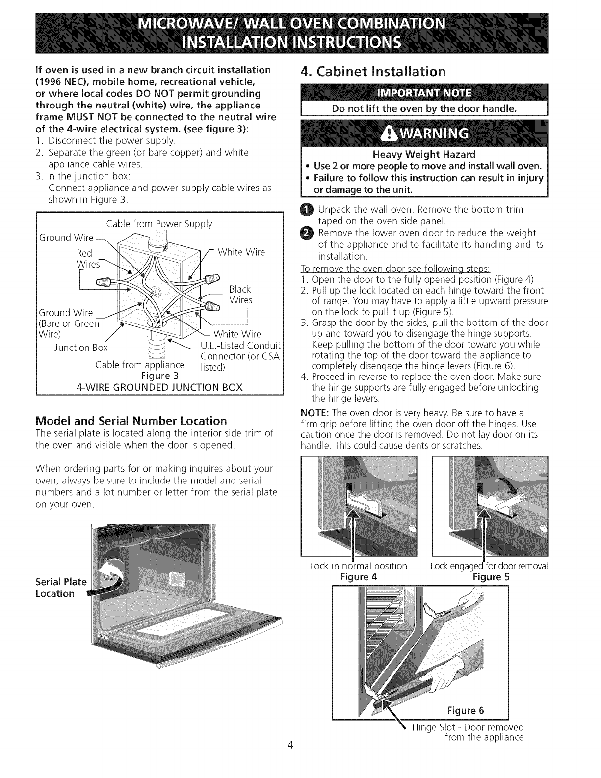
If oven is used in a new branch circuit installation
(1996 NEC), mobile home, recreational vehicle,
or where local codes DO NOT permit grounding
through the neutral (white) wire, the appliance
frame MUST NOT be connected to the neutral wire
of the 4-wire electrical system. (see figure 3):
1. Disconnect the power supply.
2. Separate the green (or bare copper) and white
appliance cable wires.
3. In the junction box:
Connect appliance and power supply cable wires as
shown in Figure 3.
Cable from Power Supply
Ground Wire
Red ___i_ _
hite Wire
Black
Ground Wire
(Bare or Green _-:__:-_ _
Wire) / _
Junction Box >,q:-:;S
4-WIRE GROUNDED JUNCTION BOX
Model and Serial Number Location
The serial plate is located along the interior side trim of
the oven and visible when the door is opened.
1
Wiris
_--__-'_"-- White Wire
"_ U.L.-Listed Conduit
Connector (or CSA
Cable from appliance listed)
Figure 3
4. Cabinet Installation
Do not lift the oven by the door handle.
Heavy Weight Hazard
• Use 2 or more people to move and install wall oven.
Failure to follow this instruction can result in injury
or damage to the unit.
0 Unpack the wall oven. Remove the bottom trim
taped on the oven side panel.
Remove the lower oven door to reduce the weight
of the appliance and to facilitate its handling and its
installation.
Toremove the oven door see following steps:
1. Open the door to the fully opened position (Figure 4).
2. Pull up the lock located on each hinge toward the front
of range. You may have to apply a little upward pressure
on the lock to pull it up (Figure 5).
3. Grasp the door by the sides, pull the bottom of the door
up and toward you to disengage the hinge supports.
Keep pulling the bottom of the door toward you while
rotating the top of the door toward the appliance to
completely disengage the hinge levers(Figure 6).
4. Proceed in reverse to replace the oven door. Make sure
the hinge supports are fully engaged before unlocking
the hinge levers.
NOTE: The oven door is very heavy. Be sure to have a
firm grip before lifting the oven door off the hinges. Use
caution once the door is removed. Do not lay door on its
handle. This could cause dents or scratches.
When ordering parts for or making inquires about your
oven, always be sure to include the model and serial
numbers and a lot number or letter from the serial plate
on your oven.
Serial Plate
Location
Lock in normal position
Figure 4
4
Lockengagedfordoor removal
Figure 5
Figure 6
Hinge Slot - Door removed
from the appliance
 Loading...