

Page 1
IMPORTANT
DO NOT REMOVE THIS BAG
OR DESTROY THE CONTENTS
WIRING DIAGRAMS AND SERVICE
INFORMATION ENCLOSED
REPLACE CONTENTS IN BAG
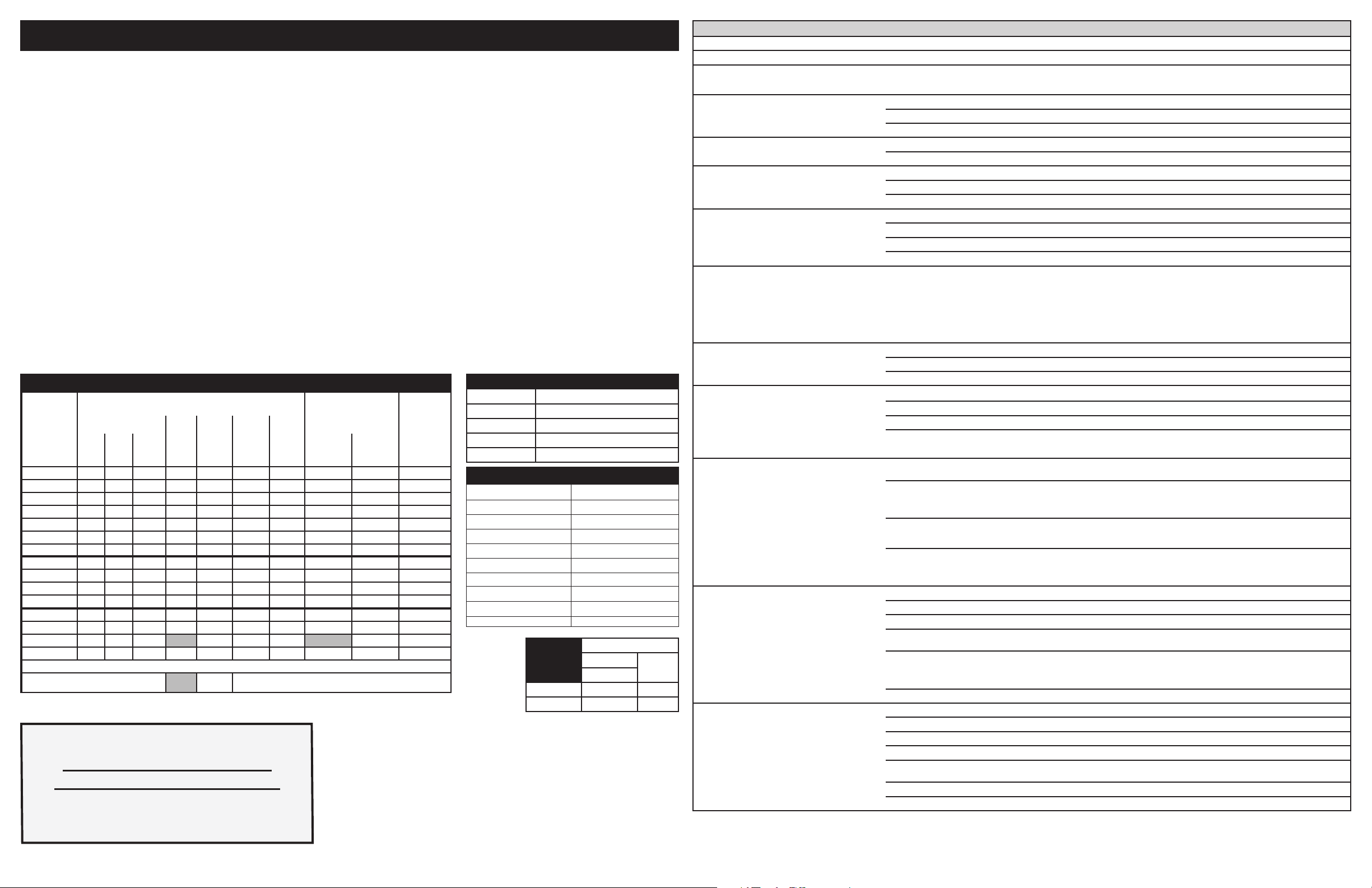
Resistance (ohms)
1000 ± 4.0
1091 ± 5.3
1453 ± 8.9
1654 ± 10.8
1852 ± 13.5
2047 ± 15.8
2237 ± 18.5
2697 ± 24.4
Open circuit/infinite resistance
RTD SCALE
Temperature °F (°C)
32 ± 1.9 (0 ± 1.0)
75 ± 2.5 (24 ± 1.3)
250 ± 4.4 (121 ± 2.4)
350 ± 5.4 (177 ± 3.0)
450 ± 6.9 (232 ± 3.8)
550 ± 8.2 (288 ± 4.5)
650 ± 9.6 (343 ± 5.3)
900 ± 13.6 (482 ±7.5)
Probe circuit to case ground
SERVICE DATA SHEET
Appliance with ES630 Electronic Oven Control
NOTICE: This service data sheet is intended for use by persons having electrical and me-
chanical training and a level of knowledge of these subjects generally considered acceptable
in the appliance repair trade. The manufacturer cannot be responsible, nor assume any
liability, for injury or damage of any kind arising from the use of this data sheet.
IMPORTANT NOTE: This unit includes an EOC (electronic oven control). This board is not
eld-repairable.
Safe Servicing Practices
To avoid the possibility of personal injury and/or property damage, it is important that safe servicing practices be observed. The following are some, but not all, examples of safe practices.
1. Do not attempt a product repair if you have any doubts as to your ability to complete it
in a safe and satisfactory manner.
2. Before servicing or moving an appliance, remove power cord from electric outlet, trip
circuit breaker to Off, or remove fuse.
3. Never interfere with the proper installation of any safety device.
4. Use only replacement parts specied for this appliance. Substitutions may not comply
with safety standards set for home appliances.
5. Grounding: The standard color coding for safety ground wires is green or green with
yellow stripes. Ground leads are not to be used as current carrying conductors. It is
extremely important that the service technician reestablish all safety grounds prior to
completion of service. Failure to do so will create a potential hazard.
6. Prior to returning the product to service, ensure that:
• All electric connections are correct and secure.
• All electrical leads are properly dressed and secured away from sharp edges,
high-temperature components, and moving parts.
• All uninsulated electrical terminals, connectors, heaters, etc. are adequately
spaced away from all metal parts and panels.
• All safety grounds (both internal and external) are correctly and securely reas-
sembled.
• All panels are properly and securely reassembled.
CIRCUIT ANALYSIS MATRIX
On Relay Board TRIAC Board On Display
ELEMENTS
Door
Motor
BakeP9BroilP7Conv.
P11
Bake X X X* X X X X*
Keep Warm X X X
Broil X X X X
Conv. Bake X X X X X X X**
Conv. Roast X X X X X X X
Conv. Broil X X X X X
Clean X X X X X
Locking X
Locked
Unlocking X
Unlocked
Light X
Door Open X
Door Closed X
Bread Proof X X X
Relay will operate in this condition only
L2 out
J3-5
DLB
P1
Cooling
Cooling
Fan
Low
J3-7
*Convection element and fan are used for the rst rise in
Fan
High
J3-8
Conv Fan
P2-7
temperature
807880703 EN (Rev A 15/02)
Oven Calibration
Set the electronic oven control for normal baking at 350°F. Allow oven to preheat to set
temperature. Obtain an average oven temperature after a minimum of ve cycles. Press the
STOP key to end the Bake mode.
Temperature Adjustment
1. Press USER PREFERENCES until you get the UPO menu page.
2. To select the oven you want to adjust, press USER PREFERENCES again to toggle
between the upper and lower display.
3. Enter the temperature by pressing the HI or LO keys. The temperature can only be
adjusted by ±35°F (°C).
4. Press START to accept the changes and go back to USER PREFERENCES menu
display.
Note: Changing calibration affects all baking modes. The adjustments made will not change
the self-cleaning temperature.
2-Speed Cooling Fan
The EOC controls the speed of the cooling fan. The cooling fan is activated at low speed
during any cooking function and will remain on until the oven is cooled down. The high speed
is activated during the broil (with open door) and during clean cycles only when the tempera-
ture is above apporximately 575°F/302°C.
Oven
Light
P2-1
Board
Door Switch
P10-3
MEAT PROBE TEMPERATURE VS RESISTANCE TABLE
Temperature Probe Resistance
77 °F / 25°C 50.020 Kohm +/- 6%
122 °F / 50°C 18.020 Kohm +/- 5%
176 °F / 80°C 6.290 Kohm +/- 5%
212 °F / 100°C 3.400 Kohm +/- 5%
LOWER
OVEN
ANALYSIS
MATRIX
Bake X X
Keep Warm X X
On Relay Board
ELEMENTS DLB L2
Bake (P10)
out (P2)
ELECTRONIC OVEN CONTROL (EOC) FAULT CODE DESCRIPTIONS
Note: Generally speaking “F1X” implies a control failure, “F3X” an oven probe problem, and “F9X” a latch motor problem.
Failure Code/ Condition/Cause Suggested Corrective Action
F10 Control has sensed a potential runaway oven
condition. Control may have shorted relay, RTD
sensor probe may have a gone bad.
F11 Shorted Key: a key has been detected as pressed
for a long period and will be considered a shorted
key alarm and will terminate all oven activity.
F13 Control's internal checksum may have become
corrupted.
F14 Misconnected keyboard cable Verify connection between display board and touch panel (2 ribbon cables). Make sure the cables are well connected at both ends.
F15 Controller self check failed. Verify if relay board receives 120VAC between J4 pin 1 and 3.
F20 The oven controller has detected a problem with
the communication link to the surface element
controller (ESEC)
F23 The controller failed to communicate with the oven
lights control board.
F30 Open RTD sensor probe/ wiring problem.
Note: EOC may initially display an "F10", thinking a runaway
condition exists.
F31 Shorted RTD sensor probe / wiring problem. Let the oven cool down and restart the function.
Note: F30 or F31 is displayed when oven is in active mode or an attempt to enter an active mode is made.
F43 The cooling fan speed, as read by the tachometer
input of the EOC-display board, is abnormally
too slow.
F44 The cooling fan speed, as read by the
tachometer input of the EOC- display board, is
abnormally too fast.
F90 Door motor mechanism failure. Press any key to clear the error.
Check RTD sensor probe and replace if necessary. If oven is overheating, disconnect power. If oven continues to overheat when power is
reapplied, replace relay board and/or display board.
Press any key to clear the error.
If fault returns, replace the keyboard (touch panel).
If the problem persists, replace the display board.
Press any key to clear the error.
Disconnect power, wait 30 seconds and reapply power. If fault returns upon power-up, replace display board.
If the cables are good, replace the touch panel.
If the problem persists, replace the display board.
Verify the wiring between J2 on the relay board and P16 on the display board.
If wiring and 120VAC supply is good replace the display board.
If problem persists replace the relay board.
1. Is the ESEC User Interface Board powered on (are the surface element displays showing something)? If not, that is the reason why the
oven control cannot communicate with it (ESEC has no power). Check the 120VAC voltage going in to the ESEC power supply board
located in the front console (connector P1) and the low voltage supply going from the power supply board (connector P2) to the ESEC
UIB (connector P7).
2. Check connections between connector P2 on the oven controller and P9 on the ESEC User Interface Board. This is the communication
link. Verify for continuity. Refer to the wiring diagram.
3. If the above steps failed to solve the problem, replace the ESEC UIB board.
4. If problem persists replace the oven controller.
Verify wiring between P2 on the display board and P2 on the oven lights control board.
If wiring is good, replace oven lights board.
If the problem persists, replace the display board.
Check wiring in probe circuit for possible open condition.
Check RTD resistance at room temperature (compare to probe resistance chart). If resistance does not match the chart, replace the RTD sensor probe.
If the problem persists, replace the display board.
Determine rst if the problem appears to be caused by a cooling fan not turning or turning slowly or by a problem with the sensing of the fan
speed. Start a Bake and check during the rst 15 seconds if the fan is turning (should feel air owing through the vent above the upper oven door).
If the fan does not appear to be turning or turn slowly check the 120VAC at the fan. If 120VAC is present at the fan motor but the fan does not
turn replace the fan motor. If 120VAC is not present at the fan motor when a Bake is started check the connection to the relay board (J3 pin
7) and Neutral: is there 120VAC on J3 pin 7? Does it reach the fan motor? Is the other terminal of the fan motor connected to Neutral? If the
harness or relay board are faulty replace them.
If the fan appears to be normally turning but an F43 error code is generated, it means there is a problem with the reading of the fan speed
sensor. Make sure the connection of the fan speed sensor is properly made (refer to wiring diagram), between the sensor on the fan and the
EOC- display board.
For trouble-shooting purposes, it is possible to enter a test mode that will indicate on the display the reading of the fan speed in RPM: to enter
the test mode, power-up the unit and within 30 seconds press and hold the upper oven Bake and Broil keys for 3 seconds (until you see all
segments in the screen illuminated). Once in the test mode, pressing the upper oven Light key once will display the fan speed in RPM. In normal
client mode the F43 error is generated for a fan speed below approximately 700 RPM.
Inspect the cooling fan. Does it appear to be turning normally (air ow, noise)? Verify the fan blade is well assembled.
Verify there is nothing blocking the air ow of the fan (that could make the fan turn faster).
Check the 120VAC voltage on the fan. A voltage higher than 120VAC + 10% could make it go too fast.
Make sure the connection of the fan speed sensor is properly made (refer to wiring diagram), between the sensor on the fan and the EOCdisplay board.
For trouble-shooting purposes, it is possible to enter a test mode that will indicate on the display the reading of the fan speed in RPM: to enter the test
mode, power-up the unit and within 30 seconds press and hold the upper oven Bake and Broil keys for 3 seconds (until you see all segments in the screen
illuminated). Once in the test mode, pressing the upper oven Light key once will display the fan speed in RPM. In normal client mode the F44 error is
generated for a fan speed above approximately 2500 RPM.
If problem persists replace both the fan+sensor assembly and the EOC- display board.
I
f it does not eliminate the problem, turn off power for 30 seconds, then turn on power.
Check wiring of Lock Motor, Lock Switch and Door Switch circuits.
Unplug the lock motor from the board and apply power (L1) directly to the Lock Motor. If the motor does not rotate, replace Lock Motor Assembly.
Check Lock Switch for proper operation (do they open and close, check with ohmmeter). The Lock Motor may be powered as in above step to
open and close Lock Switch. If the Lock Switch is defective, replace Motor Lock Assembly.
If all above steps fail to correct situation, replace the display board and/or the relay board in the event of a motor that does not rotate.
If all the above steps fail to correct the situation, replace the display board in the event of a motor that rotates endlessly.
Page 2
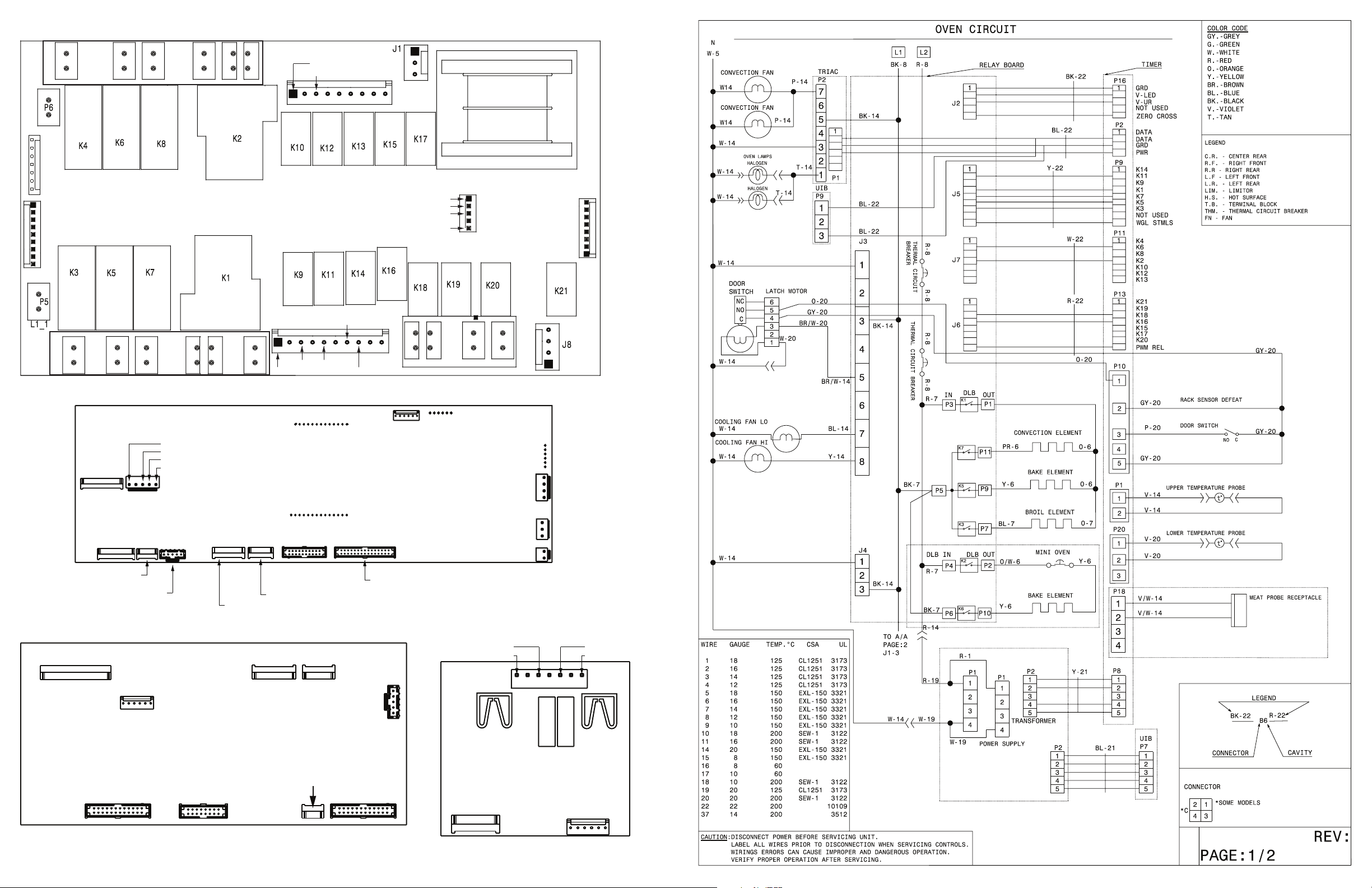
NEUTRAL
COOLING FAN - HIGH
CONV FAN
NEUTRAL
L1
RELAY BOARD
P8 P10P12 P2
LOWER OVEN
1
BAKE
BAKE
P4
P18
NEUTRAL
DLB IN
DLB OUT
BLB
L1
J4
1
1
J7 - HEAT CONTROL UPPER OVEN
CONNECTS TO
CONTROL P11
1
J5 - HEAT CONTROL LOWER OVEN
CONNECTS TO
CONTROL P9
BROIL
P7
BROIL
UPPER OVEN
BAKE
BAKE
OVEN CONTROL
P9 OUT
CONNECTS
TO J5
CONV
P3
P11P9
CONV
COMMON
DOOR SWITCH
RACK SENSOR DEFEAT
MDL
1
P10 SWITCH 1 OUT
L2 IN
P17
DLB
CONNECTS TO CONTROL P16
J3
1
P1
L2 OUT
COOLING FAN - LOW
L1
MDL
J2 DC POWER
GROUND
VLED (~+7 VDC)
VUR (~+15 VDC)
ZERO CROSS
P19
P13
P6 PROGRAMMING
HEADER
CONNECTS TO CONTROL P13
1
P15
P18 MEAT PROBE
J6 CONTROLS FAN,
NIGHT LIGHT, AUX OUTUT
1
P16
1
P13 AUX OUT
CONNECTS TO J6
P2 LIN COMM 1
CONNECTS TO TRIAC
P8 BACKLIGHT POWER CONNECTS
TO POWER SUPPLY
P3 TOUCH
KEY INPUTS
P7 EXT LEDS/KEY, RING LIGHTS, PANEL
BACKLIGHT CONTROL/POWER
P11 LOWER OVEN OUT CONNECTS TO J7
P16 POWER IN CONNECTS TO J2
P20 LOWER OVEN TEMP PROBE
P1 TEMP PROBE
USER INTERFACE BOARD (UIB) TRIAC BOARD
OVEN LAMP
P2
1
P10
P3
P9 CONNECTS TO
CONTROL P2 AND TRIAC
J2 J4 P9
P6P5
P7 CONNECTS TO
POWER SUPPLY
J3
P1 CONNECTS TO
CONTROL P2
PROGRAMMING
HEADER
P6P1
Page 3

IMPORTANT
DO NOT REMOVE THIS BAG
OR DESTROY THE CONTENTS
WIRING DIAGRAMS AND SERVICE
INFORMATION ENCLOSED
REPLACE CONTENTS IN BAG
SERVICE DATA SHEET
TAB102
TAB101
COUPE-CIRCUIT THERMIQUE
30” INDUCTION COOKTOP
NOTICE - This service data sheet is intended for use by persons having electrical
and mechanical training and a level of knowledge of these subjects generally
considered acceptable in the appliance repair trade. The manufacturer cannot
be responsible, nor assume any liability for injury or damage of any kind arising
from the use of this data sheet.
SAFE SERVICING PRACTICES
To avoid the possibility of personal injury and/or property damage, it is important
that safe servicing practices be observed. The following are examples, but without
limitation, of such practices.
1. Before servicing or moving an appliance remove power cord from electrical outlet,
trip circuit breaker to OFF, or remove fuse.
2. Never interfere with the proper installation of any safety device.
3. GROUNDING: The standard color coding for safety ground wires is GREEN or
GREEN WITH YELLOW STRIPES. Ground leads are not to be used as current
carrying conductors. It is extremely important that the service technician
reestablish all safety grounds prior to completion of service. Failure to do
so will create a potential safety hazard.
4. Prior to returning the product to service, ensure that:
• All electric connections are correct and secure.
• All electrical leads are properly dressed and secured away from sharp edges,
high-temperature components, and moving parts.
• All uninsulated electrical terminals, connectors, heaters, etc. are adequately
spaced away from all metal parts and panels.
• All safety grounds (both internal and external) are correctly and securely
reassembled.
GENERATOR BOARD LEFT
CARTE GENERATEUR GAUCHE
BPN1
BPN2
BPL2
BPL1
B81
BPE03
GENERATOR BOARD RIGHT
CARTE GENERATEUR DROITE
BPN1
BPN2
BPL2
BPL1
TAB101
TAB102
B81
BPE03
p/n 807880704 Rev A (1503)
BC3
BC4
BC5
BC1
B71
TAB1
TAB2
THERMAL CUT-OUT
COUPE-CIRCUIT THERMIQUE
Electronic Surface Element Control (ESEC)
This cooktop is equipped with an Electronic Surface Element Control (ESEC),
which precisely controls the smoothtop cooking elements at multiple settings. For
the user, the elements are operated by pressing the touch pads located on the
control panel for the desired settings. The control settings are shown in 2-digit
displays.
Hot Surface display message - If any of the induction elements are hot, the hot
surface message (HE) will display and remain ON until the cooktop cools.
ESEC lockout feature - The Cooktop Lockout features will not operate when
a surface element is ON. Conversely, the surface elements controlled by the
ESEC will not operate when Cooktop Lockout mode is active. When the control is
in Cooktop Lockout mode, will appear in the display to signify that the surface
heating elements are locked out.
* Please note: Electronic boards are very sensitive to static electricity. Static electricity can permanently damage electronic boards. Before handling these parts, be
sure to drain static electricity from your body by properly grounding yourself.
BC3
BC4
BC5
BC1
B71
TAB1
TAB2
THERMAL CUT-OUT
Indicated % Power Notes
Lo 3 Keep Warm
1.2 3.5 -
1.4 4 -
1.6 4.5 -
1.8 5 2 5.5 -
2.2 6 -
2.4 7 -
2.6 8 -
2.8 9 3 10.5 -
3.5 13 4 15.5 -
4.5 18 5 21 -
5.5 25 6 31 -
6.5 38 7 45 8 54 9 64 -
Hi 100 -
Pb 125-141 Boost
Page 4

ERROR CODES
UI Display Error Description Corrective Action
11
14 Touch panel tail missing
15/16/17 FMEA Error. Replace defective control.
20
21
23
Shorted keypad. The defective control
will ashes the error code in its display.
Loss of communication with ID1
Generator Housing Assembly.
Loss of communication with ID2
Generator Housing Assembly.
Loss of communication between 2 or
more generator.
1- Cycle power on affected zone. If stuck button comes back while zone is on then proceed.
2- Verify there is no mechanical interference near the defective control (harness, metallic devices, etc.).
3- Replace defective control.
Disconnect power, wait 30 seconds and reapply power. If fault returns:
1- Verify harnesses between ESEC-UIB and the Touch Panel.
2- Replace ESEC-UIB.
3- Replace the Touch Panel.
1- Check communication harness attached to the ID1 Induction Generator Housing. Replace if defective.
2- Verify ID1 Connection is the proper one.
3- Replace ID1 generator.
1- Check communication harness attached to the ID2 Induction Generator Housing. Replace if defective.
2- Verify ID2 Connection is the proper one.
3- Replace ID2 generator.
1- Check communication harness from UI to harnesses and generator to generator.
2- Check ID1 connection to verify that the ID jumper is connected from BC1 to BC5.
UI Display Error Description Corrective Action
71
72/73
74
76
77
Internal generator error. Sync, Induction
Housing Assembly / Right side cooking
zones.
Power Supply defect. Induction Housing
Assembly / Right side cooking zones
Internal generator error.
Communication, Induction
Housing Assembly / Right side cooking
zones.
Communication error. Induction
Housing Assembly / Right side cooking
zones.
Heat sink temperature sensor break,
Induction Housing Assembly / Right
side cooking zones.
1- Check all cables and connectors on the Right Side Generator Circuit Board, replace if defective.
2- Replace the Right Side Generator Circuit Board.
1- Test all cables & connections on Filter Circuit Board.
2- Replace the Filter Circuit Board.
3- Replace the Right Side Generator Circuit Board.
1- Check cable between Filter Circuit Board, connector X13 and the Right Side Generator Circuit Board,
connector X10.
2- Replace the Filter Circuit Board.
3- Replace the Right Side Generator Circuit Board.
1- Verify communication harness between ESEC-UIB P9 connector and Filter Circuit Board X20/X14,
replace if damaged.
2- Verify communication harness going between Filter Circuit Board, connector X13 and Right Side
Generator Circuit Board, X10 connector. Replace if defective.
3- Replace Filter Circuit Board.
4- Replace the Right Side Generator Circuit Board. 5- Replace ESEC-UIB.
Replace the Right Side Generator Circuit Board.
30/70/90
31/71/ 91 Internal generator error ID1/ ID2. Replace Induction Generator Housing ID1, ID2.
32/72/92 Power supply defect ID1/ ID2. Replace Induction Generator Housing ID1, ID2.
33/73/93 Cooling fan blocked ID1/ID2.
34/74/94 Main AC Phase error ID1/ID2 Replace generator housing ID1, ID2.
35/75/95 Main AC voltage too low ID1/ID2.
36/76/96 Internal communication error ID1/ID2. Replace generator housing ID1, ID2.
37/77/97
38/78/98 Fan not connected ID1, ID2. 1- Verify fan is correctly connected at BS1.
39
40/80/A0 IGBT heat sink sensor error ID1/ID2. 1- Verify if the heat sink sensor is installed properly (measure approx. 100kOhm for NTC).
41/81/A1 Induction sensor (coils) defect ID1/ID2.
42/82/A2 General pot detection alarm ID1/ID2.
43/83/A3 Pot detection sensor fail ID1/ID2.
44/84/A4 Board temperature warning ID1/ID2.
45/85/A5 Board temperature alarm ID1/ID2.
AC input voltage too high in either ID1,
ID2 place designated by UI display.
Internal induction generator housing
error ID1, ID2.
Conguration mismatch between
generator and UI control.
1- Verify AC Input voltage at cooktop input (customer wiring) and AC from pole.
2- Verify AC voltage between BPL and PBN connectors should measure 240V AC +- 24V AC.
3- Replace Induction Generator Housing.
1- Verify there is no interference for the fan.
2- Replace generator housing ID1, ID2.
1- Check line voltage coming into the house if all zones are showing this error.
2- Replace generator housing ID1, ID2.
Replace generator housing ID1, ID2.
2- Replace induction generator housing ID1, ID2.
1- Verify if user interface is the right one for that model.
2- Verify if generators are the correct type.
3- If all displays are showing this error replay UI otherwise replace appropriate generator.
2- Replace generator housing assembly ID1, ID2.
1- Verify if the inductor (coils) are connected properly (measure approx. 0Ohm at room temperature).
2- Replace the induction generator housing if 0 ohm otherwise the inductor (coil).
1- Verify pans are the proper type (magnet sticks to the bottom of pan).
2- Verify pan is not warped or rusty, pan is proper size, pan is placed correctly.
3- Replace induction generator housing ID1, ID2.
1- Verify pan is not warped or rusty, pan is proper size for zone, pan is placed correctly.
2- Replace induction generator housing ID1, ID2.
1- Ensure customer is not using the cooktop with a dry pan at a high temperature level.
2- Allow zone to cool down and then continue cooking.
1- Ensure customer is not using the cooktop with a dry pan at a high temperature level.
2- Replace induction generator housing ID1, ID2.
ADDITIONAL ERROR (FAULT) CONDITIONS
Symptom or failure Control Display Possible cause or condition Suggested Corrective Action
Pan does not heat up. Normal operation. Pan too small for proper pan detec-
tion and only works with low power.
Individual buttons cannot be
used or cannot always be
used.
Cooking power too low or
shuts down prematurely.
HE in display when cooking
zone is cold and switched off.
Flashing "Power level"
and pan does not heat.
None. Test cables & connections. Touch
None. Fluids spilled or object lying on
Normal operation Ventilation slots obstructed. Clear vent openings.
"HE" Temperature sensor defect. 1. Test coil sensor , approximately 100Kohms at room
Pan not detected. Check whether the pots or pans are suitable for induction. Refer to
Induction coil not correctly
connected or induction coil open.
Distance between coil and glass
ceramic too large.
control defective.
control panel keypads.
Unsuitable pots ( bottom bent). Follow owners guide for proper pan selection.
Distance between coil and glass
ceramic too large.
Use larger pan or this pan on a smaller cooking zone. Refer to
owners guide for proper pan selection.
owners guide for proper pan selection.
Check the coil wire terminal connections. Ensure that they are
properly connected and tightened. Test continuity of coil (should be
less than 1 ohm).
Check whether the coil is properly positioned and touching the glass
cooktop surface.
1. Follow instructions for proper use of touch controls. 2. Replace
Touch Control.
Clean up spills or remove objects. Restart cooktop in normal
manner.
Check whether the glass ceramic was pushed down when being
screwed in position and the coil has been correctly positioned.
temperature. Replace coil if resistance is incorrect. 2. Replace
power generator board.
51/52/53
54/55/56
63/64/65
66/67/68
Element temperature sensor failure ID1/
ID2.
Element temperature sensor too hot
ID1/ID2.
1- Verify induction temperature sensor is connected properly at B71 or B81 as per wiring diagram.
2- Verify the inductor temperature sensor is installed properly and not damaged (measure approx. 100K
Ohms at room temperature).
3- Replace induction generator housing ID1, ID2.
1- Ensure customer does not use the cooktop with a dry pan at high temperature levels.
2- Verify the inductor temperature sensor is installed properly and not damaged in the proper generator
(measure approx. 100k Ohms at room temperature).
3- Replace induction generator housing ID1, ID2.
 Loading...