

Electrolux EI30ES55JSA, EI30ES55JSB, EI30ES5CJSB, EW30ES65GBA, EW30ES65GBB Installation Guide
...
30" ELECTRIC SLIDE-IN RANGE INSTALLATION INSTRUCTIONS
F
G
E
½”
min.
3/8”
min.
½”
min.
INSTALLATION AND SERVICE MUST BE PERFORMED BY A QUALIFIED INSTALLER.
flammable vapors and liquids in the vicinity of this or any other appliance.
These surfaces should be flat &
leveled (hatched area).
Shave Raised
Edge To Clear
Space for
31 1/2"
(80 cm)
Wide
Cooktop Rim.
CanadaUnited States
IMPORTANT: SAVE FOR LOCAL ELECTRICAL INSPECTOR'S USE.
READ AND SAVE THESE INSTRUCTIONS FOR FUTURE REFERENCE.
FOR YOUR SAFETY: Do not store or use gasoline or other
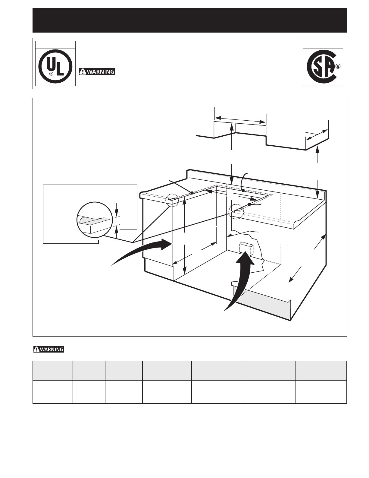
30" Min.
(76,2 cm) Min.
13"
(33 cm)
30" Min. (see Note 3)
(76,2 cm) Min. (See Note 3)
18" Min.
(45,7 cm) Min.
1 ½" Max.
(3,8 cm Max.)
Approx. 1 7/8"
(4,8 cm)
Locate Cabinet Doors 1" (2,5 cm)
Min. From Cutout Opening
Grounded Junction Box or Wall Outlet Should Be
Located 8" to 17" (20,3 - 43,2 cm) From Right
Cabinet and 2" to 4" (5,1-10,2 cm) From Floor
Do not install the unit in the cabinet before reading next two pages.
A. HEIGHT
(Under Cooktop)
35 3/4" (90,8 cm)
36 5/8" (93 cm)
B. WIDTH
30" (76,2 cm) 31 1/2"
C. COOKTOP
WIDTH
(80 cm)
D. TOTAL DEPTH TO
FRONT OF RANGE
28 5/16" (71,9 cm) 30±1/16"
E. CUTOUT WIDTH***
(Countertop
and cabinet)
(76,2±0,15 cm)
F. CUTOUT
DEPTH
21 3/4" (55,2 cm) Min.
22 1/8" (56,2 cm) Max
24" (61 cm) Min. with
backguard
24" Min.
(61 cm) Min.
G. HEIGHT
OF COUNTERTOP
35 7/8" (91,1 cm) Min.
36 5/8" (93 cm) Max.
Printed in Canada
P/N 318201615 (1212) Rev. I
1
English – pages 1-12
Español – páginas 13-24
Français – pages 25-36
30" ELECTRIC SLIDE-IN RANGE INSTALLATION INSTRUCTIONS
E
E
A
D
C
B
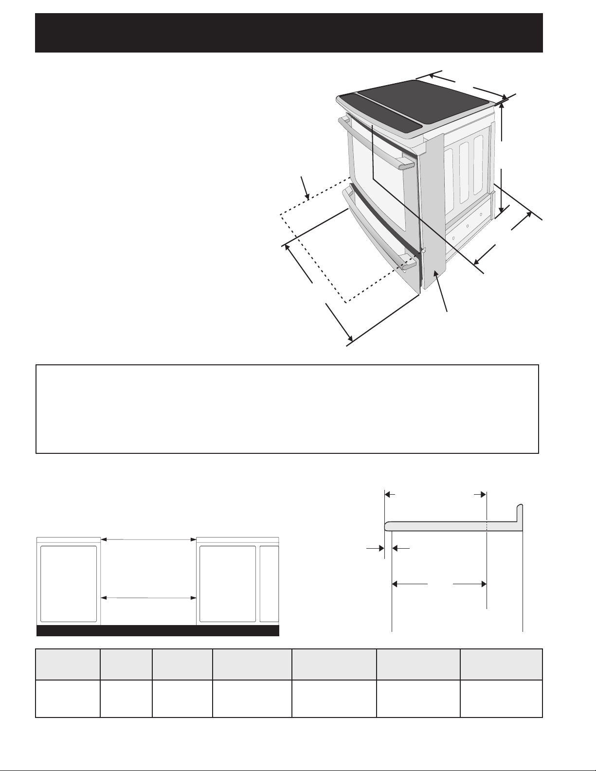
NOTE:
1. Do not pinch the power supply cord or the
flexible gas conduit between the range and
the wall.
2. Do not seal the range to the side cabinets.
3. 24" (61 cm) minimum clearance between
the cooktop and the bottom of the cabinet
when the bottom of wood or metal cabinet
is protected by not less than ¼" (0,64 cm)
flame retardant millboard covered with
not less than No. 28 MSG sheet metal,
0,015"(0,4 mm) stainless steel, 0,024"(0,6
mm) aluminum, or 0,020" (0,5 mm) copper.
30" (76,2 cm) minimum clearance when the
cabinet is unprotected.
4. For cutouts below 22 7/8"(58,1 cm),
appliance will slightly show out of the
cabinet.
5. Allow at least 19 ¼" (48,9 cm) clearance for
door depth when it is open.
Door Open
Side Panel
*** IMPORTANT: To avoid cooktop breakage for cutout width (E dimension) of more
than 30 1/16" (76,4 cm), make sure the appliance is centered in the counter opening while
pushing into it. Raise leveling legs and the rear adjustable wheels at a higher position
than the cabinet height (see page 3), insert the appliance in the counter and then level.
Make sure the unit is supported by the leveling legs at the front and the
wheels at the back and NOT by the cooktop itself.
22 7/8"(58,1 cm) min.
23 1/4"(59,05 cm) max.
(see Note 4)
IMPORTANT: Cabinet and countertop
width should match the cutout width.
A. HEIGHT
(Under Cooktop)
35 3/4" (90,8 cm)
36 5/8" (93 cm)
B. WIDTH
30" (76,2 cm) 31 1/2"
C. COOKTOP
WIDTH
(80 cm)
D. TOTAL DEPTH TO
FRONT OF RANGE
28 5/16" (71,9 cm) 30±1/16"
E. CUTOUT WIDTH***
CABINET
(Countertop
and cabinet)
(76,2±0,15 cm)
FRONT OF
1 1/8"
(2,86 cm)
F
Ref.
F. CUTOUT
DEPTH
21 3/4" (55,2 cm) Min.
22 1/8" (56,2 cm) Max
24" (61 cm) Min. with
backguard
G. HEIGHT
OF COUNTERTOP
35 7/8" (91,1 cm) Min.
36 5/8" (93 cm) Max.
2
30" ELECTRIC SLIDE-IN RANGE INSTALLATION INSTRUCTIONS
H1
H2
H3
H4
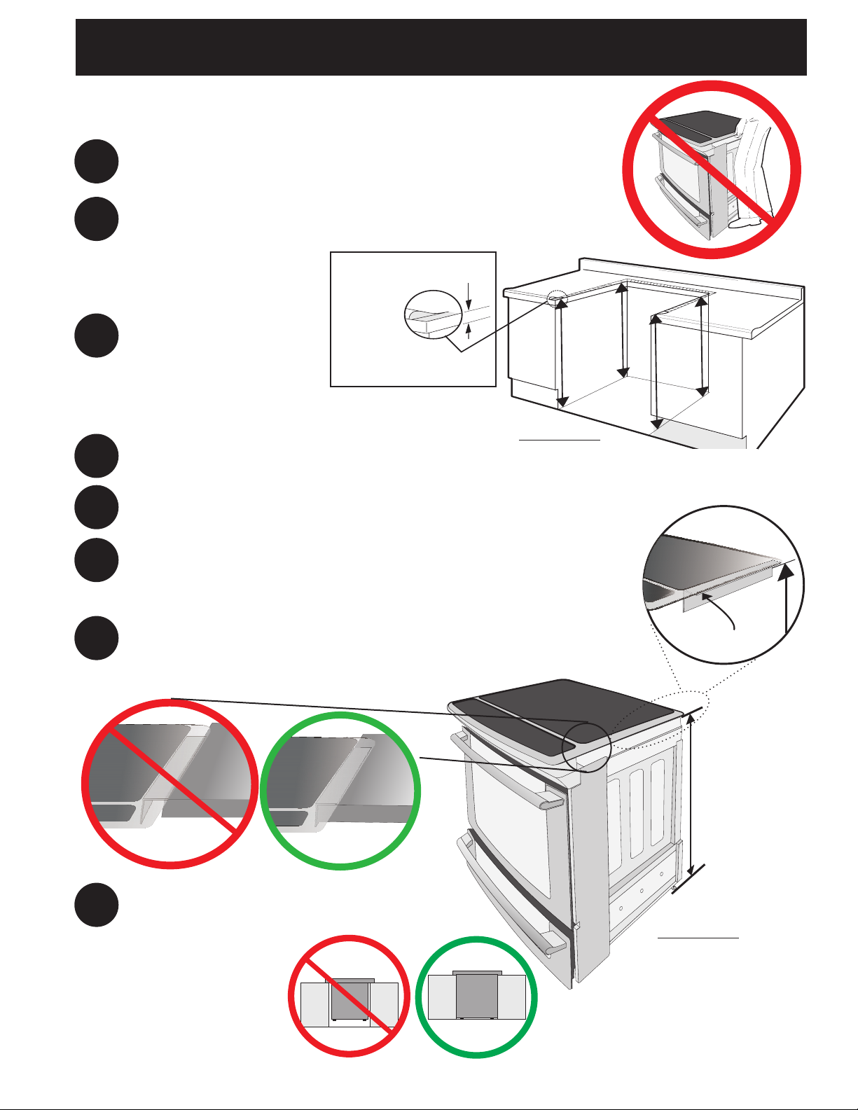
To avoid breakage: Do NOT handle or
manipulate the unit by the cooktop.
The counter-top around the cut-out should be flat and
1
leveled (see hatched area on illustration 1).
Before installing the unit, measure the heights of the two (2)
cabinet sides (H1-4), front and back (see illustration 1) from the
2
floor to the top of the counter.
Level the range using
the two (2) front leveling
legs and the two (2)
adjustable leveling wheel,
3
so that the height from
the floor to the underside
Shave
Raised
Edge
to Clear
Space for a
31½" (81 cm)
Wide Cooktop.
of the metal flange is
greater than the tallest cabinet measurement by
at least 1/16" (see illustration 2).
Remove and discard the two rear leveling legs,
4
they are only in place to solidify the unit for the transport.
1 ½" Max.
(3.8 cm Max.)
Illustration 1
Slide the unit into the cabinet. Make sure the center of the unit is
5
aligned with the center of the cabinet cut-out.
Remove the protective channels on each side of the cooktop
6
(if provided).
The metal flange under each side of the cooktop MUST be
placed over the cabinet countertop for proper unit support.
The cooktop should NOT rest directly on the countertop (see
7
illustration 2) or else it could cause damage to the cooktop
voiding the warranty. Level the unit if needed.
After the installation, MAKE SURE that the
unit is supported by the two front leveling
8
legs and the two adjustable leveling wheels
and NOT by the cooktop.
Metal
Flange
To successfully install
the range, the initial
level height from
floor to underside
of cooktop frame
should be at least
1/16" taller than
cabine t si d es as
measured in step 2.
Illustration 2
3
30" ELECTRIC SLIDE-IN RANGE INSTALLATION INSTRUCTIONS
Important Notes to the Installer
1. Read all instructions contained in these installation
instructions before installing range.
2. Remove all packing material from the oven
compartments before connecting the electrical supply
to the range.
3. Observe all governing codes and ordinances.
4. Be sure to leave these instructions with the consumer.
Important Note to the Consumer
Keep these instructions with your Owner's Guide for the
local electrical inspector's use and future reference.
IMPORTANT SAFETY
INSTRUCTIONS
Cold temperatures can damage the
electronic control. When using the appliance for the first
time, or when the appliance has not been used for an
extended period of time, be certain the unit has been
in temperatures above 32°F (0°C) for at least 3 hours
before turning on the power to the appliance.
• Be sure your range is installed and grounded
properly by a qualified installer or service
technician.
•This range must be electrically grounded in
accordance with local codes or, in their absence,
with the National Electrical Code ANSI/NFPA No.
70—latest edition in United States or with CSA
Standard C22.1, Canadian Electrical Code, Part 1 in
Canada.
•Theinstallationofappliancesdesignedfor
manufactured (mobile) home installation must conform
with Manufactured Home Construction and Safety
Standard, title 24CFR, part 3280 [Formerly the Federal
Standard for Mobile Home Construction and Safety,
title 24, HUD (part 280)] or when such standard
is not applicable, the Standard for Manufactured
Home Installation 1982 (Manufactured Home Sites,
Communities and Setups), ANSI Z225.1/NFPA 501Alatest edition, or with local codes in United States and
with CAN/CSA-Z240 MH in Canada.
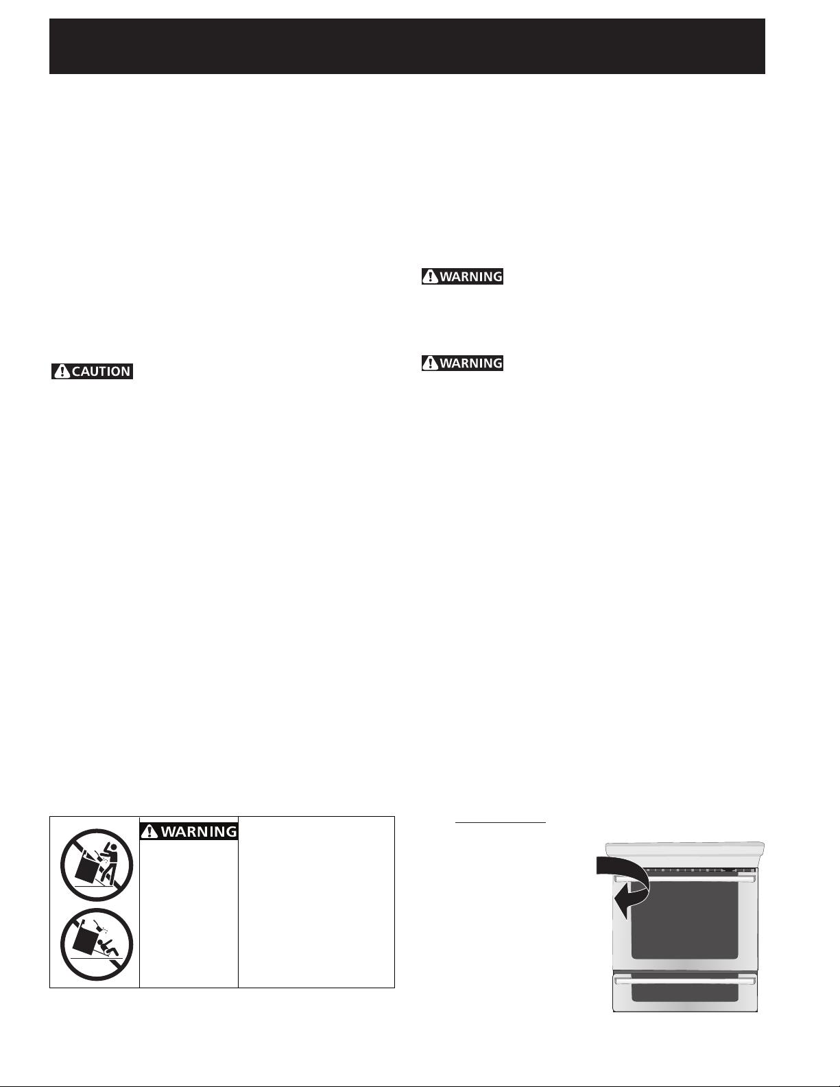
To reduce the risk of tipping
• Allranges
can tip.
• Injuryto
persons
could result.
• Installanti-
tip device
packed with
range.
of the range, the range
must be secured by properly
installed anti-tip bracket(s)
provided with the range.
To check if the bracket(s), is
installed properly, grasp the
top rear edge of the range
and carefully tilt it forward
to make sure the range is
anchored.
•Make sure the wall coverings around the range
can withstand the heat generated by the range.
•Before installing the range in an area covered
with linoleum or any other synthetic floor
covering, make sure the floor covering can
withstand heat at least 90°F (32.2°C) above room
temperature without shrinking, warping or
discoloring. Do not install the range over carpeting
unless you place an insulating pad or sheet of ¼"
(0.64 cm) thick plywood between the range and
carpeting.
Never leave children alone or
unattended in the area where an appliance is in
use. As children grow, teach them the proper, safe use
of all appliances. Never leave the oven door open when
the range is unattended.
Stepping, leaning or sitting on the
door or drawer of this range can result in serious
injuries and can also cause damage to the range.
•Do not store items of interest to children in
the cabinets above the range. Children could be
seriously burned climbing on the range to reach items.
•To eliminate the risk of burns or fire by reaching
over heated surface units, cabinet storage
space above the surface unit should be avoided.
If cabinet storage is to be provided the risk can
be reduce by installing a range hood that project
horizontally a minimum of 5 inches beyond the bottom
of the cabinet.
•Do not use the oven as a storage space. This
creates a potentially hazardous situation.
•Never use your range for warming or heating the
room. Prolonged use of the range without adequate
ventilation can be dangerous.
•Do not store or use gasoline or other flammable
vapors and liquids near this or any other
appliance. Explosions or fires could result.
•Reset all controls to the "off" position after using
a programmable timing operation.
FOR MODELS WITH SELF-CLEAN FEATURE:
•Remove oven racks, broiler pan, food and other
utensils before self-cleaning the oven. Wipe up
excess spillage. Follow the precleaning instructions in
the Owner's Guide.
Serial Plate Location
You will find the model and
serial number printed on the
serial plate. The serial plate is
located as shown.
Remember to record the
serial number for future
reference.
4
 Loading...