

Electrolux EW30GC55GB1, EW30GC55GS1, EW30GC55GW1, EW30GC60IS1, EW36GC55GB1 Installation Guide
...Page 1
INSTALLATION AND SERVICE MUST BE PERFORMED BY A QUALIFIED INSTALLER.
IMPORTANT: SAVE FOR LOCAL ELECTRICAL INSPECTOR'S USE.
READ AND SAVE THESE INSTRUCTIONS FOR FUTURE REFERENCE.
If the information in this manual is not followed exactly, a fire or explosion may result
causing property damage, personal injury or death.
FOR YOUR SAFETY:
-- Do not store or use gasoline or other flammable vapors and liquids in
the vicinity of this or any other appliance.
-- WHAT TO DO IF YOU SMELL GAS:
• Do not try to light any appliance.
• Do not touch any electrical switch; do not use any phone in your building.
• Immediately call your gas supplier from a neighbor's phone.
Follow the gas supplier's instructions.
• If you cannot reach your gas supplier, call the fire department.
-- Installation and service must be performed by a qualified installer,
service agency or the gas supplier.
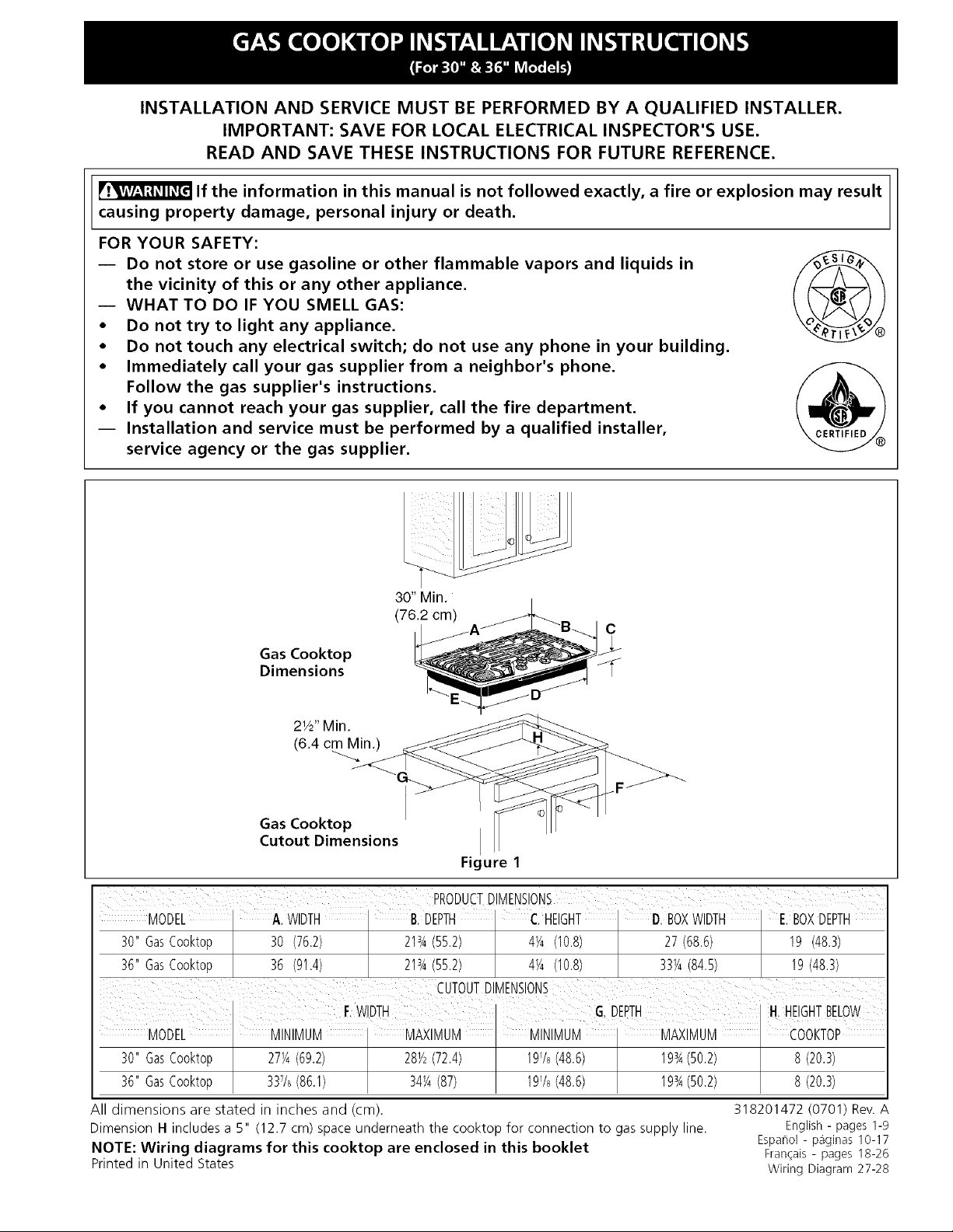
30" Min.
(76.2 cm)
C
Gas Cooktop
Dimensions
21/2"Min.
(6.4 cm Min.)
Gas Cooktop
Cutout Dimensions
Figure 1
MODEL A.WIDTH B.DEPTH C HEIGHT D.BOXWIDTH E.BOXDEPTH
30"GasCooktop 30 (76.2) 213A(55.2) 4_A(10.8) 27(68.6) 19 (48.3)
36"GasCooktop 36 (91.4) 213A(55.2) 4_A(10.8) 331/4(84.5) 19(48.3)
MODEL MINIMUM MAXIMUM MINIMUM MAXIMUM COOKTOP
30"GasCooktop 271/4(69.2) 281/2(72.4) 191/8(48.6) 1934(50.2) 8(20.3)
36"GasCooktop 337/8(86.1) 34_A(87) 191/8(48.6) 1934(50.2) 8(20.3)
All dimensions are stated in inches and (cm).
Dimension H includes a 5" (12.7 cm) space underneath the cooktop for connection to gas supply line.
NOTE: Wiring diagrams for this cooktop are enclosed in this booklet
Printed in United States
318201472 (O701) Rev. A
Espahol- paginas 10-17
Fran_ais - pages 18-26
Wiring Diagram 27-28
English - pages 1-9
Page 2
Important Notes to the Installer
1. Readall instructions contained in these installation
instructions before installing the cooktop.
2. Remove all packing material before connecting the
electrical supply to the cooktop.
3. Observe all governing codes and ordinances.
4. Be sure to leave these instructions with the consumer.
5. Note: For operation at 2000 ft. elevations above see
level, appliance rating shall be reduced by 4 percent
for each additional 1000 ft.
Important Note to the Consumer
Keep these instructions with your Useand Care Guide for
future reference.
IMPORTANT SAFETY
INSTRUCTIONS
Installation of this cooktop must conform with local codes
or, in the absence of local codes, with the National Fuel
Gas Code ANSI Z223.1/NFPA 54 in the United States, or
in Canada, with the Canadian Fuel Gas Code, CAN/CGA
B149 and CAN/CGA B149.2.
• When installed in a manufactured (mobile) home
installation must conform with the Manufactured Home
Construction and Safety Standard, title 24 CFR, part
3280 [Formerly the Federal Standard for Mobile Home
Construction and Safety, title 24, HUD (part 280)] or,
when such standard is not applicable, the Standard for
Manufactured Home Installation, ANSI/NCSBCS A225.1
or with local codes where applicable.
This cooktop has been design certified by CSA
International. As with any appliance using gas and
generating heat, there are certain safety precautions you
should follow. You will find them in the Useand Care
Guide, read it carefully.
• Be sure your cooktop is installed and grounded
properly by a qualified installer or service
technician.
• This cooktop must be electrically grounded in
accordance with local codes or, in their absence,
with the National Electrical Code ANSI/NFPA No.
70--latest edition in the United States, or in
Canada, with the Canadian Electrical Code, CSA
C22.1 Part 1.
• The burners can be lit manually during an
electrical power outage. To light a burner, hold a
lit match to the burner head, then slowly turn the
Surface Control knob to LITE. Use caution when
lighting burners manually.
• Do not store items of interest to children in
cabinets above the cooktop. Children could be
seriously burned climbing on the cooktop to reach
items.
• To eliminate the need to reach over the surface
burners, cabinet storage space above the burners
should be avoided.
• Adjust surface burner flame size so it does not
extend beyond the edge of the cooking utensil.
Excessive flame is hazardous.
• Never use your cooktop for warming or heating
the room. Prolonged use of the cooktop without
adequate ventilation can be hazardous.
• Do not store or use gasoline or other flammable
vapors and liquids near this or any other
appliance. Explosions or fires could result.
The electrical power to the cooktop
must be shut off while gas line connections are
being made. Failure to do so could result in serious
injury or death.
Page 3
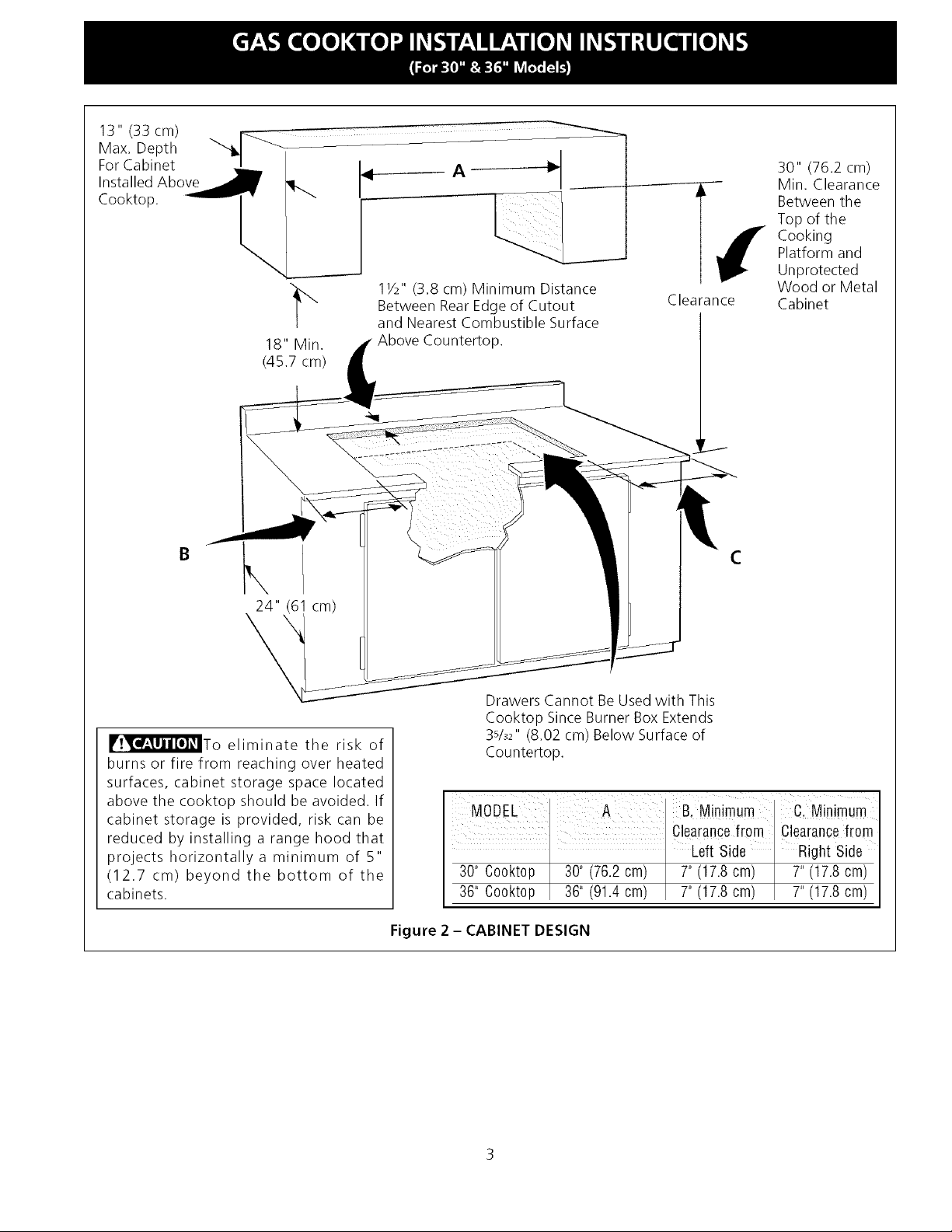
13"(33cm)
Max.Depth
ForCabinet
InstalledAbove
Cooktop.
18" Min.
(45.7 cm)
A
1V2" (3.8 cm) Minimum Distance
Between RearEdge of Cutout
and Nearest Combustible Surface
Above Countertop.
4
Clearance
30" (76.2 cm)
Min. Clearance
Between the
Top of the
Cooking
Platform and
Unprotected
Wood or Metal
Cabinet
C
24" cm)
\
_To eliminate the risk of
burns or fire from reaching over heated
surfaces, cabinet storage space located
above the cooktop should be avoided. If
cabinet storage is provided, risk can be
reduced by installing a range hood that
projects horizontally a minimum of 5"
(12.7 cm) beyond the bottom of the
cabinets.
Drawers Cannot Be Used with This
Cooktop Since Burner Box Extends
3sh2" (8.02 cm) Below Surface of
Countertop.
MODEL A B, Minimum C. Minimum
Clearancef[om Clearancefrom
I I Left Side I Right Side
30" Cooktop 30" (76.2 cm) I 7"(17.8 cm) I 7" (17.8 cm)
36" Cooktop 36" (91.4 cm) 7"(17.8 cm) 7"(17.8 cm)
Figure 2 - CABINET DESIGN
Page 4
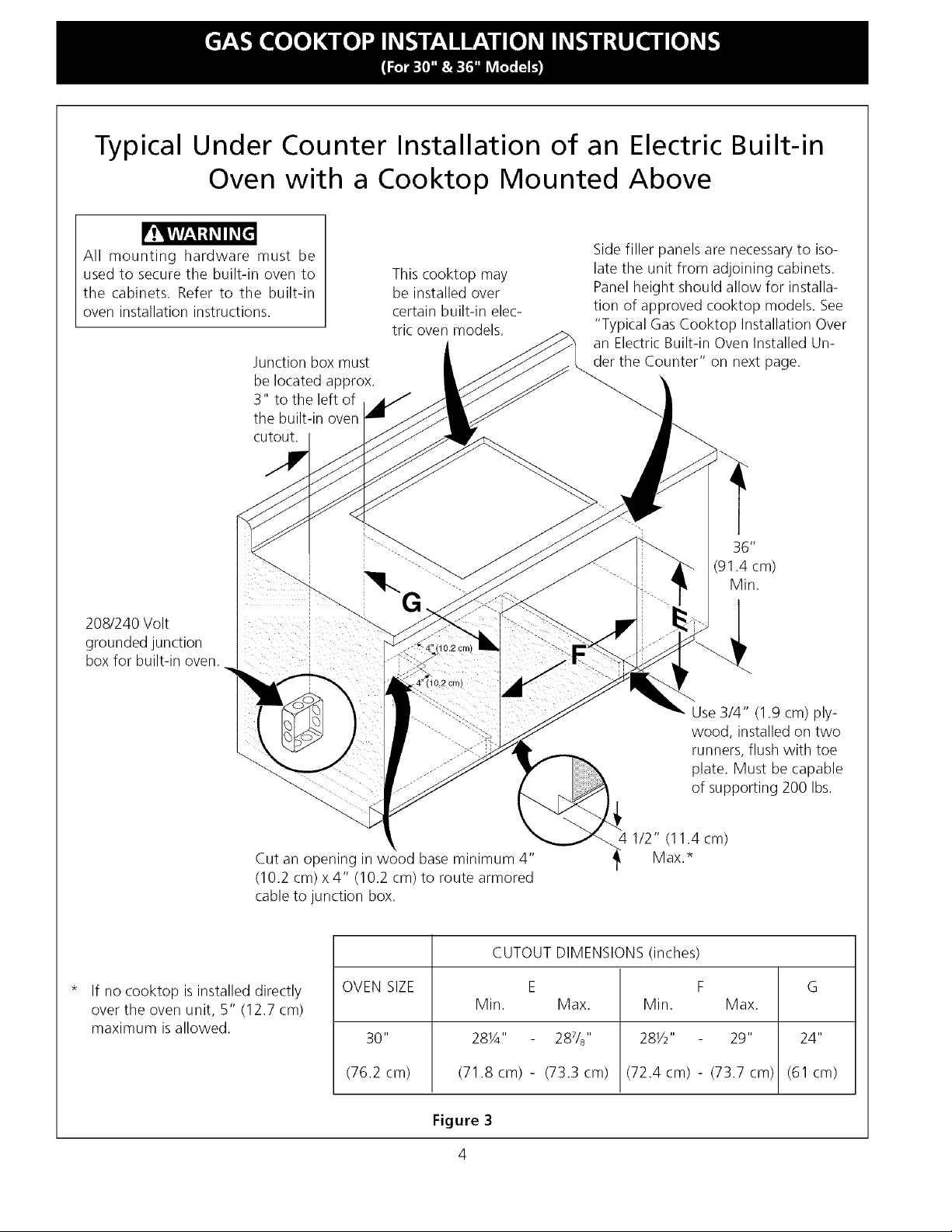
Typical Under Counter Installation of an Electric Built-in
Oven with a Cooktop Mounted Above
All mounting hardware must be
used to secure the built-in oven to
the cabinets. Refer to the built-in
oven installation instructions.
Junction box must
be located approx.
3" to the left of
the built-in oven
cutout.
208/240 Volt
grounded junction
box for built-in oven.
This cooktop may
be installed over
certain built-in elec-
tric oven models.
G •
Side filler panels are necessary to iso-
late the unit from adjoining cabinets.
Panel height should allow for installa-
tion of approved cooktop models. See
"Typical Gas Cooktop Installation Over
an Electric Built-in Oven Installed Un-
der the Counter" on next page.
36"
(91.4 cm)
Min.
Cut an opening in wood base minimum 4"
(10.2 cm) x4" (10.2 cm) to route armored
cable to junction box.
If no cooktop is installed directly
over the oven unit, 5" (12.7 cm)
maximum isallowed.
Use 3/4" (1.9 cm) ply-
wood, installed on two
runners, flush with toe
plate. Must be capable
of supporting 200 Ibs.
-,_4 1/2" (11.4 cm)
CUTOUT DIMENSIONS (inches)
OVEN SIZE E F G
Min. Max. Min. Max.
30" 28¼" 287/8'' 28Y2" 29" 24"
(76.2 cm) (71.8 cm) - (73.3 cm) (72.4 cm) - (73.7 cm) (61 cm)
Figure 3
4
Max.*
Page 5
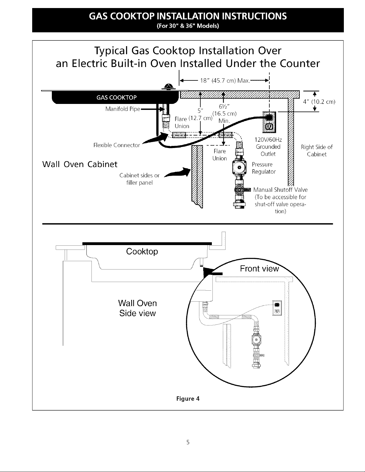
Typical Gas Cooktop Installation Over
Electric Built-in Oven Installed Under the Counter
an
18" (45.7 cm) Max.----_
Wall
Manifold Pi
Flexible Connector
Oven Cabinet
_L Cooktop
Cabinet sidesor
filler panel
61/2"
5" ,(16.5 cm)
Flare (12.7cm) Min.
Union
Union
- Flare
_J
_J
120V/6OHz
Grounded
Outlet
Pressure
Regulator
Manual Shutoff Valve
(To be accessible for
shut-off valveopera-
tion)
Front
4" (10.2 cm)
Right Side of
Cabinet
Wall Oven
Side view
Figure 4
Page 6
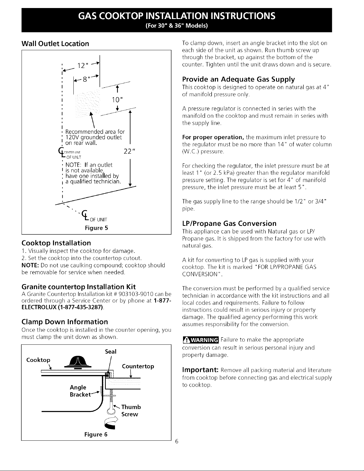
Wall Outlet Location
12 ''_
: 10"
i i iiii iii i:
Recommended area for
120V grounded outlet
on rear wall.
_ OFUINNET 22"
NOTE: If an outlet
I is not available
have one installed by
i a qualified technician. _,
• I_OF UNIT
Figure 5
Cooktop Installation
1. Visually inspect the cooktop for damage.
2. Set the cooktop into the countertop cutout.
NOTE: Do not use caulking compound; cooktop should
be removable for service when needed.
To clamp down, insert an angle bracket into the slot on
each side of the unit as shown. Run thumb screw up
through the bracket, up against the bottom of the
counter. Tighten until the unit draws down and issecure.
Provide an Adequate Gas Supply
This cooktop is designed to operate on natural gas at 4"
of manifold pressure only.
A pressure regulator is connected in series with the
manifold on the cooktop and must remain in series with
the supply line.
For proper operation, the maximum inlet pressure to
the regulator must be no more than 14" of water column
(W.C.) pressure.
For checking the regulator, the inlet pressure must be at
least 1" (or 2.5 kPa) greater than the regulator manifold
pressure setting. The regulator is set for 4" of manifold
pressure, the inlet pressure must be at least 5".
The gas supply line to the range should be 1/2" or 3/4"
pipe.
LP/Propane Gas Conversion
This appliance can be used with Natural gas or LP/
Propane gas. It is shipped from the factory for use with
natural gas.
A kit for converting to LPgas is supplied with your
cooktop. The kit is marked "FOR LP/PROPANEGAS
CONVERSION".
Granite countertop Installation Kit
A Granite Countertop Installation kit # 903103-9010 can be
ordered through a Service Center or by phone at 1-877-
ELECTROLUX(1-877-435-3287).
Clamp Down Information
Once the cooktop is installed in the counter opening, you
must clamp the unit down as shown.
Seal
Cooktop
I
Figure 6
The conversion must be performed by a qualified service
technician in accordance with the kit instructions and all
local codes and requirements. Failure to follow
instructions could result in serious injury or property
damage. The qualified agency performing this work
assumes responsibility for the conversion.
Failure to make the appropriate
conversion can result in serious personal injury and
property damage.
Important: Remove all packing material and literature
from cooktop before connecting gas and electrical supply
to cooktop.
6
Page 7
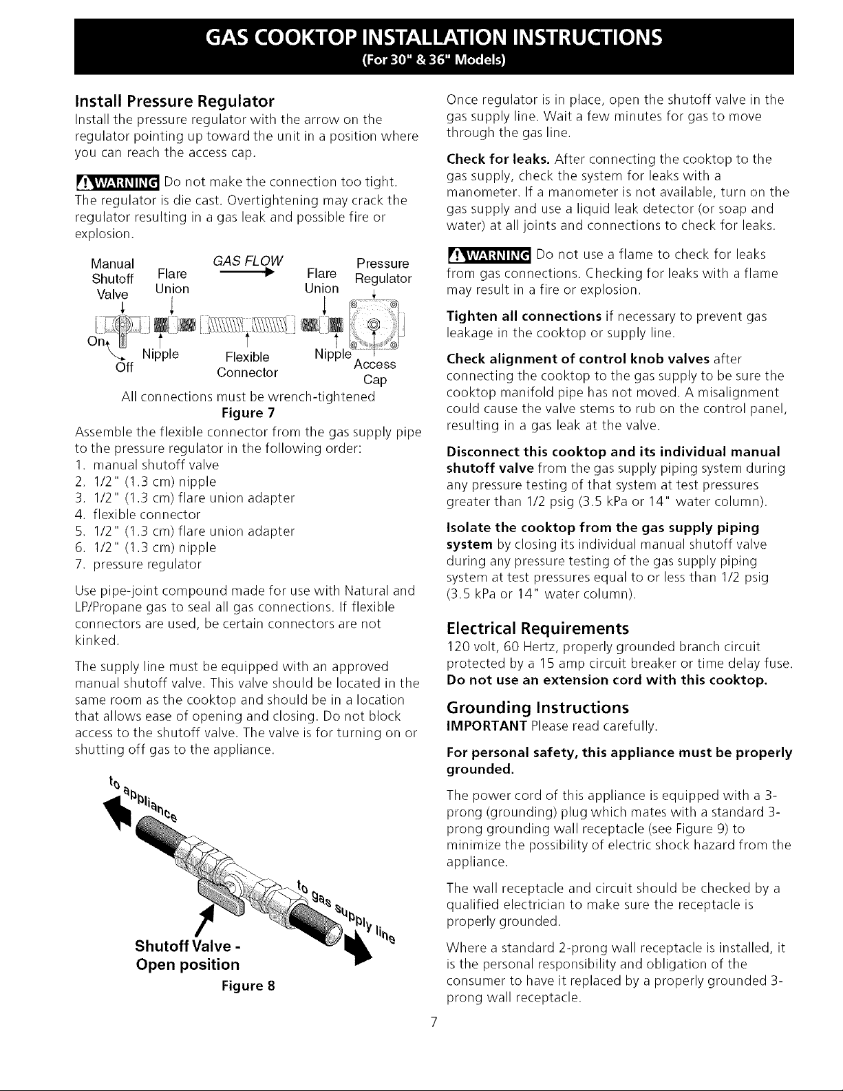
Install Pressure Regulator
Installthepressureregulatorwiththearrowonthe
regulatorpointinguptowardtheunitinapositionwhere
youcanreachtheaccesscap.
Donotmaketheconnectiontootight.
Theregulatorisdiecast.Overtighteningmaycrackthe
regulatorresultinginagasleakandpossiblefireor
explosion.
Manual GAS FLOW Pressure
Shutoff Flare _-I_ Flare Regulator
Valve Union Union ,
On, L i J
X.. Nipple Flexible
Off Connector
All connections must be wrench-tightened
Figure 7
Assemble the flexible connector from the gas supply pipe
to the pressure regulator in the following order:
1. manual shutoff valve
2. 1/2" (1.3 cm) nipple
3. 1/2" (1.3 cm) flare union adapter
4. flexible connector
5. 1/2" (1.3 cm) flare union adapter
6. I/2" (1.3 cm) nipple
7. pressure regulator
Use pipe-joint compound made for use with Natural and
LP/Propane gas to seal all gas connections. If flexible
connectors are used, be certain connectors are not
kinked.
The supply line must be equipped with an approved
manual shutoff valve. This valve should be located in the
same room as the cooktop and should be in a location
that allows ease of opening and closing. Do not block
access to the shutoff valve. The valve is for turning on or
shutting off gas to the appliance.
Access
Cap
Once regulator is in place, open the shutoff valve in the
gas supply line. Wait a few minutes for gas to move
through the gas line.
Check for leaks. After connecting the cooktop to the
gas supply, check the system for leaks with a
manometer. If a manometer is not available, turn on the
gas supply and use a liquid leak detector (or soap and
water) at all joints and connections to check for leaks.
Do not use a flame to check for leaks
from gas connections. Checking for leaks with a flame
may result in a fire or explosion.
Tighten all connections if necessary to prevent gas
leakage in the cooktop or supply line.
Check alignment of control knob valves after
connecting the cooktop to the gas supply to be sure the
cooktop manifold pipe has not moved. A misalignment
could cause the valve stems to rub on the control panel,
resulting in a gas leak at the valve.
Disconnect this cooktop and its individual manual
shutoff valve from the gas supply piping system during
any pressure testing of that system at test pressures
greater than 1/2 psig (3.5 kPa or 14" water column).
Isolate the cooktop from the gas supply piping
system by closing its individual manual shutoff valve
during any pressure testing of the gas supply piping
system at test pressures equal to or less than 1/2 psig
(3.5 kPa or 14" water column).
Electrical Requirements
120 volt, 60 Hertz, properly grounded branch circuit
protected by a 15 amp circuit breaker or time delay fuse.
Do not use an extension cord with this cooktop.
Grounding Instructions
IMPORTANT Please read carefully.
For personal safety, this appliance must be properly
grounded.
Shutoff Valve -
Open position
Figure 8
The power cord of this appliance is equipped with a 3-
prong (grounding) plug which mates with a standard 3-
prong grounding wall receptacle (see Figure 9) to
minimize the possibility of electric shock hazard from the
appliance.
The wall receptacle and circuit should be checked by a
qualified electrician to make sure the receptacle is
properly grounded.
Where a standard 2-prong wall receptacle is installed, it
is the personal responsibility and obligation of the
consumer to have it replaced by a properly grounded 3-
prong wall receptacle.
Page 8
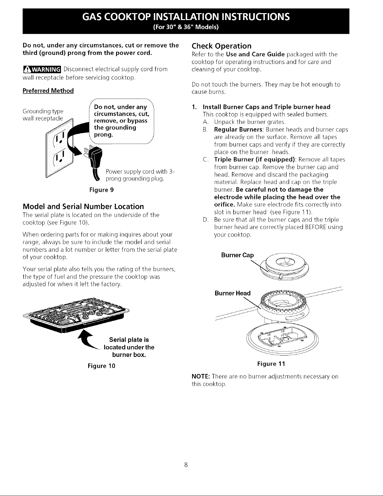
Do not, under any circumstances, cut or remove the
third (ground) prong from the power cord.
Disconnect electrical supply cord from
wall receptacle before servicing cooktop.
Preferred Method
Grounding type
wall receptacle
Power supply cord with 3-
prong grounding plug.
Figure 9
Model and Serial Number Location
The serial plate is located on the underside of the
cooktop (see Figure 10).
When ordering parts for or making inquires about your
range, always be sure to include the model and serial
numbers and a lot number or letter from the serial plate
of your cooktop.
Check Operation
Refer to the Use and Care Guide packaged with the
cooktop for operating instructions and for care and
cleaning of your cooktop.
Do not touch the burners. They may be hot enough to
cause burns.
,
Install Burner Caps and Triple burner head
This cooktop is equipped with sealed burners.
A. Unpack the burner grates.
B. Regular Burners: Burner heads and burner caps
are already on the surface. Remove all tapes
from burner caps and verify if they are correctly
place on the burner heads.
C. Triple Burner (if equipped): Remove all tapes
from burner cap. Remove the burner cap and
head. Remove and discard the packaging
material. Replace head and cap on the triple
burner. Be careful not to damage the
electrode while placing the head over the
orifice. Make sure electrode fits correctly into
slot in burner head (see Figure 11).
D. Be sure that all the burner caps and the triple
burner head are correctly placed BEFOREusing
your cooktop.
Your serial plate also tells you the rating of the burners,
the type of fuel and the pressure the cooktop was
adjusted for when it left the factory.
Serial plate is
located under the
burner box.
Figure 10
Burner Ca_
Burner Head
Figure 11
NOTE: There are no burner adjustments necessary on
this cooktop.
Page 9
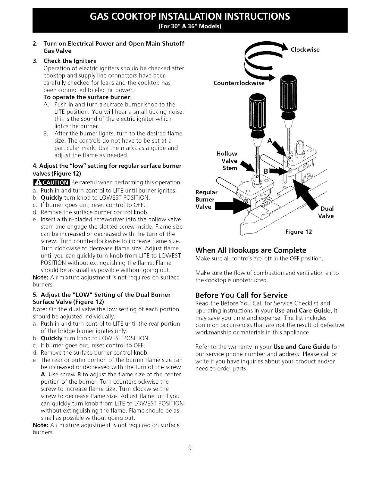
2. Turn on Electrical Power and Open Main Shutoff
Gas Valve
3. Check the Igniters
Operation of electric igniters should be checked after
cooktop and supply line connectors have been
carefully checked for leaks and the cooktop has
been connected to electric power.
To operate the surface burner:
A. Push in and turn a surface burner knob to the
LITEposition. You will hear a small ticking noise;
this isthe sound of the electric ignitor which
lights the burner.
B. After the burner lights, turn to the desired flame
size. The controls do not have to be set at a
particular mark. Use the marks as a guide and
adjust the flame as needed.
4. Adjust the "low" setting for regular surface burner
valves (Figure 12)
Becareful when performing this operation.
a. Push in and turn control to LITEuntil burner ignites.
b. Quickly turn knob to LOWEST POSITION.
c. If burner goes out, reset control to OFF.
d. Remove the surface burner control knob.
e. Insert athin-bladed screwdriver into the hollow valve
stem and engage the slotted screw inside. Flame size
can be increased or decreased with the turn of the
screw. Turn counterclockwise to increase flame size.
Turn clockwise to decrease flame size. Adjust flame
until you can quickly turn knob from LITEto LOWEST
POSITIONwithout extinguishing the flame. Flame
should be as small as possible without going out.
Note: Air mixture adjustment is not required on surface
burners.
Clockwise
Counterclo_
Hollow
Valve
Stem
Regular
Burner
Valve
Figure 12
Dual
Valve
When All Hookups are Complete
Make sure all controls are left in the OFFposition.
Make sure the flow of combustion and ventilation air to
the cooktop is unobstructed.
5. Adjust the "LOW" Setting of the Dual Burner
Surface Valve (Figure 12)
Note: On the dual valve the low setting of each portion
should be adjusted individually.
a. Push in and turn control to LITEuntil the rear portion
of the bridge burner ignites only.
b. Quickly turn knob to LOWEST POSITION.
c. If burner goes out, reset control to OFF.
d. Remove the surface burner control knob.
e. The rear or outer portion of the burner flame size can
be increased or decreased with the turn of the screw
A. Use screw B to adjust the flame size of the center
portion of the burner. Turn counterclockwise the
screw to increase flame size. Turn clockwise the
screw to decrease flame size. Adjust flame until you
can quickly turn knob from LITEto LOWESTPOSITION
without extinguishing the flame. Flame should be as
small as possible without going out.
Note: Air mixture adjustment is not required on surface
burners.
Before You Call for Service
Read the Before You Call for Service Checklist and
operating instructions in your Use and Care Guide. It
may save you time and expense. The list includes
common occurrences that are not the result of defective
workmanship or materials in this appliance.
Refer to the warranty in your Use and Care Guide for
our service phone number and address. Please call or
write if you have inquiries about your product and/or
need to order parts.
Page 10

LA INSTALACION Y EL SERVICIO DEBEN SER REALIZADOS POR UN INSTALADOR CALIFICADO.
IMPORTANTE: GUARDE ESTAS INSTRUCCIONES PARA USO DEL INSPECTOR ELI_CTRICO LOCAL.
LEA Y GUARDE ESTAS INSTRUCCIONES PARA FUTURAS REFERENCIAS
Si todas las instrucciones de este manual no son observadas a la letra, se puede
ocurrir incendios o explosiones que pueden causar da6os materiales, lesiones o la muerte.
PARA SU SEGURIDAD:
-- No almacene o utilice gasolina u otros vapores y liquidos inflamables cerca
de este o cualquier otro artefacto.
-- QUE HACER SI HAY FUGAS DE GAS :
• No intente de encender ningun artefacto
• No toque ningun interruptor el&trico; no utilice ningun aparato telefonico en su edifi
• Llame inmediatamente el abastecedor de gas desde el telefono de un vecino. Siga
las instrucciones del abastecedor de gas.
• En caso que no puede contactar el abastecedor de gas Ilame al departamento de
bomberos.
--La instalacion y el servicio telefonico deben ser realizados por un instalador
calificado, por un servicio tecnico certificado o por el abastecedor de gas.
30" Min.
(76.2 cm)
Dimensiones
de la parrilla de
cocinar
2V2" Min.
(6.4 cm Min.)
C
Dimensiones
del hueco de la
parrilla de cocinar
Figure 1
MODELO A.ANCHURA B.PROFUNDIDAD C.ALTURA D ANCHODELACAJA E.PROFUNDIDADDELACAJA
Modelo30" 30(76.2) 213A(55.2) 41/+(10.8) 27(68.6) 19(48.3)
Modelo36" 36(91.4) 213A(55.2) 41/+(10.8) 33IA(84.5) 19(48.3)
DIMENSIONESDELHUECODELAPARRILLADECOCINAR
6 PRoFuNDiDAD H ALTU_PoR
MODELO MINIMA MAXIMA MINIMA MAXIMA DB#JODELABTUFA
Modelo30" 271/4(692) 28I/2(72.4) 191/+(48.6) 193A(50.2) 8(20.3)
Modelo36" 337/s(86.1) 341/4(87) 191/+(48.6) 193A(50.2) 8(20.3)
Todas las dimensiones se dan en pulgasdas (cm).
La dimensi6n H incluye un espacio de 5" por debajo de la plancha de cocinar para la conexi6n 318201472 (O701) Rev.A
de la linea de suministro de gas, English- pages1-9
NOTA: Se adjunta los diagramas de cables de esta plancha de cocinar con el libreta. Espafi_ol- paginas 10-17
Imprimido en los Estados Unidos Diagrama de la instalaci6n alfimbrica - pfiginas 27-28
Fran%is- pages18-26
Page 11

Notas importantes para el instalador:
1. Lea todas lasinstrucciones de instalaci6n antes de
realizar la instalaci6n de la plancha de cocinar.
2. Retire todos los articulos de embalaje antes de realizar
lasconexiones el6ctricas a la plancha de cocinar.
3. Observe todos los c6digos o reglamentos estatales
4. Aseg0rese que el consumidor tenga estas instrucciones.
5. Nota: Para el correcto funcionamiento en lugares
superiores a los 2000 ft, el regimen del mecanismo
debe reducirse un 4% por cada 1000 ft sobre el nivel
del mar.
Notas importantes para el consumidor
Guarde todas las instrucciones con su manual del usuario
para futuras referiencias.
INSTRUCCIONES DE
SEGURIDAD IMPORTANTES
La instalaci6n de esta plancha de cocinar debe realizarse
en conformidad con los c6digos locales o, siestos no
existen, con el National Fuel Gas Code ANSI Z223.1/NFPA
54 en los Estados Unidos, o en Canada, con el Canadian
FuelGas Code, CAN/CGA B149 y CAN/CGA B149.2.
° La instalaci6n de aparatos disehados para instalacion
en casas prefabricadas (moviles) debe conformar con el
Maufactured Home Consturction and Safet Standard,
titulo 24CFR, parte 3280 [Anteriormente el Federal
Standard for Mobil Home Construction and Safety,
titulo 24, HUD (parte 280)] o cuando tal estandar no se
aplica, el Standard fo Manufactured Home Installation,
ANSI/NCSBCS 225.1, o con los c6digos locales.
Eldiseho de esta plancha de cocinar cuenta con la
aprobaci6n de la CSA internacional. AI igual que todos
losartefactos a gas que generan calor, deben seguirse
ciertas medidas de seguridad. Vienen con el Manual del
Usuario. Lea atentamente el manual.
• Asegurese que la plancha de cocinar sea instalada
y puesta a tierra correctamente por un instalador
o t&cnico calificado.
° La plancha de cocinar debe conectarse
el&ctricamente a tierra de acuerdo con los c6digos
locales o, de no existir, con el c6digo el&ctrico
ANSI/NFPA No. 70 - ultima edici6n en los Estados
Unidos, or in Canada, con el Canadian Electrical
Code, CSA C22.1 Parte 1.
• Los quemadores pueden encenderse
manualmente durante una interrupci6n del
suministro el&ctrico. Para encender un quemador,
mantenga un f6sforo encendido en el extremo
del quemador, luego gire suavemente la perilla
hasta LITE (encendido). Tenga cuidado al
encender los quemadores en forma manual.
• No deje articulos que interesan los niEos en los
armarios que est_n sobre la la plancha de cocinar.
Les podria causar quernaduras graves si intentan
subirse para alcanzarlos.
• Para eliminar el riesgo de extender por encima de
los quemadores superiores, deberia evitar el
espacio de almacenamiento del armario,
Iocalizado por encima de estos quemadores
° Gradue el tamaEo de la llama de modo que no
sobrepase el borde del utensilio de cocina.
Demasiada llama es peligrosa.
• No utilice jam_s la cocina como calefactor. El uso
prolongado de la cocina sin la ventilaci6n adecuada
puede ser peligroso.
° Mantenga el _rea cerca de este artefacto o de
cualquier otro artefacto despejada de sustancias
combustibles, gasolina y otros liquidos
inflamables. Se puede ocurrir incendios o
explosiones.
r -__ El suministro el&ctrico a la plancha
de cocinar debe de ser cerrado durante las
conexiones a la linea. De Io contrario se puede
resultar lesiones graves o la muerte.
Ubicacion de la toma de corriente de la pared
,, 12,,_"
J
' JT
, ...............10"
,"
I
Area recomendada la toma de
, corriente a tierra de 120V en
I la pared posterior.
D E L
APARATO
i NOTA: Si no existe una toma
, de corriente, contacte a un
, electricista calificado para
I reaiizar la instaiaciOn. _,
"" _r__ADpARISO L
Figura 5
Z2"
11
Page 12

Max,profundidad
degabinetes
instaladospor
encimadela
planchade
empotares13"
(33cm).
18" Min.
(45.7 cm)
24" cm)
A
11/2"(3.8 cm) Minimo Distancia
entre el borde posterior del
hueco y la mas cerca superficie
combustible por encima del
mostrador.
Espacio
4
C
30" (76.2 cm)
Minimo de
espacio entre
la parte
superio de la
plataforma de
la plancha de
cocinar y el
fondo de una
madera non
protegida o
armario
metalico.
\
r_ Para eliminar el riesgo de
alargar sobre los unidades en calentamiento
de la superficie, deberia evitarse el espacio de
almacenamiento del armario, ubicado sobre
las unidades de la superficie. Si secuenta con
este espacio, se puede disminuir el peligro
instalando una cubierta de cocina que se
extienda horizontalmente en 5" (12.7 cm)
minimo pot sobre la parte inferior delantera
en los armarios.
Figura 2 - DESEI_IODEL ARMARIO
No es posible utilisar cajones con
esta parrilla de cocinar porqu_ la
caja de empalme se extiende de
35/32"(8.02 cm) pot encima de la
superficie del mostrador.
MoDELo DEI A I B.EsPacio I ClEsPaCiO
RLANCHADEI IminimodesdeelI mfnimodesde
COCINARDE I I ladoizquierdo I elladoderecho
30"Cooktop 30"(76.2 cm) I 7"(17.8 ore) I 7"(17.8 cm)
36"Cooktop 36"(91.4cm) 7" (17.8cm) 7" (17.8cm)
12
Page 13

Tipica instalacion de un horno electrico empotrado con una
plancha de cocinar por encima
Entrepaflos Ilenador de lados son
necesarios para aislar el aparato de los
armarios adyacentes. La altura de panel
Todas las fijaciones de
montaje deben de estar
utilizadas para sujetar el
homo empotrado a los
armarios. Refiere alas
instrucciones de
instalacion del homo
empotrado.
Esta plancha de cocinar puede instalarse
por encima de algunos modelos de homo
electrico empotrado.
Aproximadamente 3"
(7.6 cm)
debe de permitir la instalaci6n de
modelos de planchas de cocinar
aprobantes. Vet "lnstalaci6n tipica de
plancha de cocinar a gas por encima de
un homo electrico empotrado instalado
Jebajo del mostrador" en la pagina 4.
36"
(91.4 cm)
Minimo
Caja de empalme a tierra
208/240 voltaje para homo
empotrado
* (Si no hay plancha de cocinar
instalada directamente sobre el
aparato, un maximo de 5" (12.7
cm) esta permitido)
** Un minimo de 32" (81.3 cm)
desde la parte superior del
armario hasta la parte superior de
las ruedas debe de set
mantenido.
Corte una abertura en la basa de madera
minimo 4" (10.2 cm) x 4" (10.2 cm) para
conducir el cable blindado a la caja de
empalme.
DIMENSIONES DEL HUECO (pulgadas)
Tamaflo
del homo
30"
(76.2 cm)
Min. M,:ix. Min. M_x.
27¼" 285/8'' 281/2" 29"
(69.2 cm) - (72.7 cm) (72.4 cm) - (73.7 cm)
Figura 3
Utilice 3/4" (1.9 cm) de madera
contrachapada, instalada sobre 2 ruedas,
perpendicular a una cima de contorno de
)laca. Debe de poder sostener 150 Ibs.
E F
G
231/2,,
(59.7 cm)
13
Page 14

Instalacion tipica de la plancha de cocinar a gas por encima de un horno
electrico empotrado instalado debajo del mostrador
Tubo mOIti
Cabinet sidesor
filler panel
Armario del horno de pared
I '
UniOn
18" (45.7 cm) Max._ I
61/2"
5" (13.5 cm)
(12.7cm) Min.
Uni6n
120V/60Hz
Toma de
corriente a
regultaJ_Ode
presion
Valvula de cierre manual
(Debe de ser accessible para el
Ifunciona-miento de la valvula de
Uni6n
I
4" (10.2cm)
Lado derecho
del armario
cierre)
ESTUFA DE GAS
Vista de lado del
horno de pared
Figura 4
14
Page 15

Instalacion de la plancha de coccinar
1. Examine visualmente la plancha de cocinar para saber
si hay daho.
2. Fije el la plancha de cocinar en el recorte del mostrador.
El kit de instalacion para una cubierta en
granito
Un kit de instalaci6n # 903103-9010 para una cubierta de
granito se puede pedir a traves de un centro de servicio, o
al telefono en 1-877-4ELECTROLUX (1-877-435-3287).
Informacion para sujetar el aparato
Una vez que el aparato esta instalado en la apertura del
mostrador, se tiene que sujetar como se indica.
Plancha
de cocinar_
r
.A._ estanqueidad
Consola de [_
escuadra I
Junta de
/ Mostrador
J " Torni !o de
orejas
Figura 6
Para hacer la conversion del gas natural al gas propano, es
necesario utilizar el servicio de un t_cnico calificado, in
acuerdo con lasinstrucciones del fabricante y todos los
codigos y reglamentos reguladores. Sitodas las
instrucciones no son observadas, se puede ocurrir severos
lesiones o daflos materiales. La agencia calificada que
hace el trabajo asuma la responsabilidad para la
conversi6n.
_i".,t;1=[o_!u[o,)[o)_
observada, se puede ocurrir severos lesiones o dafios
materiales.
Importante: Retire todos los articulos de embalaje y
folletos de la cocina antes de realizar las conexiones de gas
y electricas a la cocina.
Si la conversi6n apropiada no esta
Instalacion del regulador de presion
Instale el regulador de presion con la flecha del regulador
apuntando hacia la unidad en una posici6n que permita
alcanzar la tapa de entrada.
No ajuste demasiado la conexi6n. El
regular estafundida a presi6n. AI ajustar demasiado se
puede romper el regulador causando una fuga de gas y un
posible incendio o explosi6n.
Paraajustar el aparato, inserte la consola de escuadra, con
el lado desviado,en las ranuras en cada lado del aparato.
Eltornillo de orejas debe entonces de pasar a traves del
soporte y hasta la parte de abajo del mostrador. Aprietelo
hasta que el aparato se quede ajustado.
Provea un adecuado suministro de gas
Estaplancha de cocinar esta diseflada para utilizar gas
natural de 4" de presi6n multiple solamente.
Se conecta un regulador de presi6n en serie al multiple de
la plancha de cocinar y debe permanecer en serie con la
linea de suministro de gas.
Para que manejo correcto, la presi6n de entrada
maxima hacia el regulador no debe exceder 14" de
presi6n de la columna de agua.
Para controlar el regulador, la presi6n de entrada debe set
de al menos 1" (o 2.5 Kpa) mayor que el ajuste de la
presi6n del multiple del regulador. El regulador seajusta
a 4" de la presi6n del multiple, la presi6n de entrada debe
de set de al menos 5".
La linea de suministro de gas por el horno deberia tener
un tubo de 1/2" o de 3/4".
Conversion de gas propano/licuado
Esta plancha de cocinar ha sido diseflada para utilizar gas
naturalogaspropano. Hasidofijadaenlafabricapara
utilizarse con gas natural.
Si deseahacer la conversi6n para utilizar el gas propano, use
laspiezas con orificios fijados provitos en el paquete del
manual de instrucciones para la instalaci6n en el paquete
escrito "PARA LA CONVERSIONENGASPROPANO". Siga las
instrucciones que estan con los orificios.
Valvula de FLUJO DEL GAS Regulator
cierre Uni6n Uni6n de presi6n
manual _,
Apagado flexible Tapa de
(off) entrada
Todas las conexiones deben ajustarse con
una Ilave de tuerca
Figura 7
Monte el conector flexible del tubo del suministro de gas al
regulador de presion en funcionamiento:
1. valvula de cierre manual
2. boquilla de 1/2" (1.3 cm)
3. adaptor de 1/2" (1.3 cm)
4. conector flexible
5. adaptator de 1/2" (1.3 cm)
6. boquilla de 1/2" (1.3 cm)
7. regulador de presion.
Utilice un compuesto de tubo articulado para uso de gas
natural y propano para sellar todas las conexiones de gas.
Si se utilizan conectores flexibles, aseg0rese que los
conectores no estan torcidos.
El tubo de suministro de gas debreria incluir una valvula de
cierre certificada. Estavalvula deberia estar ubicada en la
misma habitacioln de la plancha de coninar y deberia estar
en un lugar que permita una abertura y cierre faciles. No
bloquee lasentradas de la valvula de cierre. Lavalvula sirve
para abrir o cerrar el paso del gas al artefacto.
15
-
Page 16

Vfilvula de cierre -
Abierta
Figura 8
Abra lavalvula de cierre en el tubo de suministro de gas.
Espere unos minutos para que el gas pase a traves del
tubo de gas.
Verifique si hay fugas. Luego de conectar la cocina al
gas, verifique el sistema con un man6metro. Si no cuenta
con 6ste instrumento, de la vuelta al suministro de gas de
la cocina y utilice un detector de fugas liquidas (o agua y
jabon) en todas las articulaciones y conexiones para
verificar si existen fugas.
No use ning0n tipo de llama para
verificar si hay fugas de gas. Verifique si hay fugas con una
llama puede occasionar incendio o explosi6n.
Ajuste todas las conexiones en caso que sea necesario,
para evitar fugas de gas en la cocina o en el tubo de
sumininistro de gas.
Verifique la alineaci6n de las vfilvulas luego de
conectar la plancha de cocinar al suministro de gas para
asegurar que no se ha movido lavalvula del m01tiple de la
plancha de cocinar.
Desconecte la cocina y su vfilvula de cierre individual
del sistema de tuberia del suministro de gas durante
cualquier ensayo de presi6n del sistema en ensayos de
presion superiores a 1/2 psig (3.5 kPa o 14" colomna de
agua).
Aparte la cocina del sistema de tuberia del suministro
de gas cierrando su valvula de cierre individual manual,
durante cualquier ensayo de presi6n del systema de
suministro de gas en ensayos iguales o inferiores a 1/2 psig
(3.5 kPao 14" colomna de agua).
Requerimientos el&tricos
Un circuito derivado conectado correctamente a tierra de
120 voltios, 60 Herz protegido por un interruptor
automatico de 15 amp o un fusible de retardo. No utilice
un cable flexible de extensi6n en esta plancha de
cocinar.
Instrucciones para la puesta a tierra
IMPORTANTE Porfavor, lea atentamente.
Como medida de seguridad personal, est& artefacto
debe conectarse a tierra correctarnente.
El cable de encendido de este artefacto incluye un enchufe
de tres patas (a tierra) que calza con un enchufe de pared
de tres patas de conexi6n a tierra (vet Figura 9) para
disminuir la posibilidad de peligro de choques electricos
desde el artefacto.
Un electricista calificado debe verificar el enchufe de pared
y el circuito para asegurar que el enchufe esta conectado a
tierra correctamente.
Encaso de encontrarse con un enchufe de pared de dos
patas, es la personal responsibilidad y la obligaci6n del
consumidor reemplazarlo pot el enchufe de pared a tierra
de tres patas correspondiente.
No debe, bajo ninguna circunstancia cortar o retirar
la tercera pata (tierra) del cable de encendido.
_:_=:t:(_a_._[o_n Desconecte el cable del suministro
electrico del enchufe de pared antes de reparar la plancha
de cocinar.
MleTODO PREFERIDO
Enchure de
pared a tierra
Figura 9 patas a tierra
debe,
encendido.
Cablo de encendido
con enchufe de tres
Modelo y ubicacion del n_mero de serie
La placa de numero de serie esta ubicada en el lado de
abajo de la caja de quemadores (vea la figura 10).
Aseg0rese de incluir el modelo, n0mero de serie y el
n0mero o letra del Iote que se encuentran en la placa, en
todo pedido de partes o solicitud de informaci6n acerca
de su plancha de cocinar.
La placa de numero de serie tambien indica las
especificaciones de los quemadores, el tipo de
combustible y la presi6n para la cual fu_ ajustada la
plancha de cocinar en la fabrk
La placa de se-
rie esta ubicada
Figura 10 bajo la hornilla.
Verifique la operation
Refiera al Manual del Usuario que viene con la plancha de
cocinar para las instrucciones de funcionamiento y el
mantenimiento y la limpieza de su plancha de cocinar.
No toque a los quemadores. Pueden estar suficientemente
calientes par causar quemaduras.
1. Instale las tapas de los quemadores y la base del
quemador triple. La plancha de cocinar esta equipada
con quemadores sellados.
A. Desempaque las parillas de los quemadores.
B. Quemadores regulares: Las bases y las tapas de los
quemadores se encuentran sobre lasuperficie. Remueva
16
Page 17

todaslascintasdelasbasesdelos
quemadoresyverifiquequeestos
seencuentrenacomodados Tapadel
correctamentesobrelabasedel quemadore
quemador. Basedel
C. Quemador triple (si esta
equipada):
Remueva todas las cintas de Ins
basesde los quemadores.
Remueva la tapa y la base del
quemador. Remueva y deseche
el material de empaque. Vuelva Figura 11
a poner la tapa y la base del
quemador. Tenga cuidadode no da_ar el electrodo
mientras remplaza la base encima del orificio.
Esteseguro de que el electrodo siente correctamente dentro de
la ranura de la basedel quemador (yea Figura11)
D. Aseguresede que todas lastapasy la basedelquemador
2. Abre el suministro el&ctrico y la v_lvula de cierre
principal del gas.
3. Verifique los dispositivos de encendido
La manipulacion de los dispositivos de encendido
electrico deberia verificarse tras haber revisado
detenidamente la plancha de cocinar y los conectores
del tubo del suministro de fugas y tras haber
conectado la plancha de cocinar al suministro electrico.
Para operar en la superficie del quemador:
A. Presione y gire la perilla de control hasta LITE.Se
escuchara a un pequeho ruido. Estees el ruido
producido por el dispositivo de encendido electrico
cuando enciende el quemador.
B. Una vez que el quemador esta encendido, gire
hasta obtener el tamaflo de la llama deseada. No
es necesario ajustar los controles en una marca
determinada. Use las marcas como guia y ajuste la
llama seg0n se desea.
4. Ajuste bajo ("LO") ara la v_lvula de los
quernadores de superficie (Figura 12)
a. Presione y gire el control hasta la position LITEpara
prender los quemadores.
b.Gire r,_pidamente gire la perilla a la POSICIONMAS BAJA.
c. Si el quemador se apaga, reajuste el control a OFE
d. Retire la perilla del quemador de superficie.
e. Inserte un destornillador fino-aplanado en el orifico del
vastago de la valvula e inserte en el tornillo ranurado.
El tamaflo de la llama puede aumentarse o disminuirse
dandole vuelta al tornillo. De vuelta en sentido
opuesto alas manecillas del reloj para aumentar el
tamaflo de la llama. D_ vuelta en sentido a las
manecillas del reloj para disminuir la llama. Ajuste la
llama hasta que usted puede dar vuelta rapidamente a
la perilla de la posicion LITEa la POSICIONMAS BAJA
sin extinguir la llama. La llama debe ser tan pequefla
como sea posible sin apagarse.
Nota: El ajuste de la mezcla del aire no se requiere en
los quemadores de superficie
5. Ajuste bajo "LOW" para la v_lvula de quemador
de superficie puente o triple (Figura 12) (algunos
rnodelos) Nota: En la valvula de quernador triple el
ajuste <<LOW>>de cada porcion se debe ajustar
individualmente.
a. Presione y gire el control a la posici6n LITEhasta que la
porci6n posterior del quemador puente seencienda.
b. Gire r,_pidamente a la perilla a la POSICIONMAS
BAJA.
c, Si el quemador se apaga, reajuste el control a OFE
d. Retire la perilla del quemador de superficie,
e. Eltamaflo de la flama de la porci6n posterior o exterior
del quemador puede aumentarse o disminuirse
dandole vuelta al tornillo A, Utilice el tornillo B para
ajustar el tamaflo de la llama de la porci6n central del
quemador. D_ vuelta en sentido opuesto de las
manecillas del reloj para aumentar el tamaflo de la
llama. D_ vuelta en sentido a las manecillas del reloj
para disminuir la llama, Ajuste la llama hasta que usted
puede dar vuelta rapidamente a la perilla de la posici6n
LITEa la POSICION MAS A Ensentido de las
BAJAsin _,_l_manecillas del
extinguir la
llama. La
llama debe
ser tan
pequefla
como sea El hueco del
posible sin vastago de la
apagarse, valvula
Nota: El V,_lvula de
ajuste de la
mezcla del quemador
aire no se regular
requiere en
los quemadores de superficie.
Ensentido _ reloj
opuesto a las_
manecillas del
reloj
Figura 12
su|
_lvula del
quemador
Puente o
Triple
Cuando se han realizado todos los sistemas
de conexion
Aseg0rese que todos los controlos estan en la posici6n de
OFF(apagado),
Aseg0rese que el flujo de combusti 6n ' ventilaci6n de
aire de la cocina no estan obstruidos
Antes de Ilamar al servicio
Lea la secci6n Lista de Control de Averias en su Manual
delUsuario. Estolepodraahorrartiempoygastos. Esta
lista incluye ocurrencias comunes que no son el
resultado de defectos de materiales o fabricaci6n de
este artefacto.
Lea la garantia y la informaci6n sobre el servicio en su
Manual del Usuario para obtener el numero de telefono
y la dirreci6n del servicio. Por favor Ilame o escriba si
tiene preguntas acerca de su estufa o necesita
repuestos.
17
Page 18

UN INSTALLATEUR QUALIFIE DOlT EFFECTUER L'INSTALLATION ET LE SERVICE
IMPORTANT: CONSERVEZ CES INSTRUCTIONS POUR LES INSPECTEURS LOCAUX.
LISEZ CES INSTRUCTIONS ET CONSERVEZ-LES POUR RI_FERENCES ULTERIEURES.
Si les instructions de ce manuel ne sont pas suivies a la lettre, il pourrait en resulter un
incendie ou une explosion susceptible de causer des dommages materiels, des blessures ou m_me la mort.
POUR VOTRE SI_CURITI_:
-- N'entreposez et n'utilisez pas d'essence ou d'autres produits inflammables a proximite de
cet appareil ou de tout autre appareil.
-- QUE FAIRE SI VOUS DI_CELEZUNE ODEUR DE GAZ:
• Ne tentez d'allumer aucun appareil.
• N'actionnez aucun interrupteur electrique; n'utilisez aucun appareil telephonique de I'edifice.
• Communiquez immediatement avec votre fournisseur de gaz en vous servant du telephone
d'un voisin. Suivez les instructions que le fournisseur vous donnera.
• S'il vous est impossible de rejoindre votre distributeur de gaz, communiquez avec le service
d'incendie.
-- I.'installation et I'entretien doivent _tre effectues par un installateur qualifie, un service
d'entretien ou de reparation accredite ou le distributeur de gaz.
30" Min.
(76.2 cm)
C
Dimensions de la
plaque de cuisson _-
Dimensions de d&coupage pour
la plaque de cuisson
Figure 1
DIMENSIONSDELAPLAQUEDECUISSON
MODELES ' A. LARGEUR B.PROFONDEURC. HAUTEUR D.LARGEURDUBO]TIER E. PROFONDEURDUBO]TIER
Mo@les30" 30(76.2) 213A(55.2) 4_A(10.8) 27(68.6) 19 (48.3)
Uo@les36" 36(91.4) 213A(55.2) 4_A(10.8) 331/4(84.5) 19(48.3)
DIMENSIONSDEDEOUPAGE
I" ,AuiEuRSous
MODULES MINIMUM MAXIMUM MINIMUM MAXIMUM LA PLAQUEDECUISSON
Mo@les30" I 27_,;_(69.2) 28_,5(72.4) 191/8(48.6) 19_,4(50.2) 8 (20.3)
Mo@les36" I 337/8(86.1) 341/4(87) 191/8(48.6) 19_,4(50.2) 8 (20.3)
I
Toutes les dimensions sont en pouces (cm). 318201471 (0611) Rev.
La dimension H est le d_gagement requis sous la plaque de cuisson pour le raccordement au gaz. English- pages1-9
NOTE: Le sch&ma de c_blage de la plaque de cuisson est indus _ la fin de ce feuillet. Francais- pages18-26
Imprim_ aux Etats-Unis Schemasde c_blage- pages 27-28
Espa_ol- paginas 10-17
Page 19

Notes importantes & I'lnstallateur
1. Liseztoutes les instructions contenues dans ce feuillet
avant d'installer I'appareil.
2. Enlevez tout le materiel d'emballage avant de connec-
ter I'alimentation de gaz a la plaque de cuisson.
3. Respecteztousles codes et reglements applicables.
4. N'oubliez pas de laisser ces instructions au consomma-
teur.
5. Note: Pour I'utilisation _ plus de 2000 pieds d'elevation
au dessus du niveau de lamer, la puissance de I'appa-
reil devrait _tre reduite de 4% pour chaque 1000 pieds
additionnels.
Note importante au consommateur
Conservez ces instructions avec le guide de I'utilisateur
pour reference ult_rieure.
INSTRUCTIONS DE SI:!:CURITI:!:
IMPORTANTES
Cet appareil doit 6tre installe conform_ment aux
reglements Iocaux, ou en I'absence de reglements, au
code National de Gaz ANSI Z223.1/NFPA 54 aux Etats-
Unis, ou aux normes CAN/ACG-B149 et CAN/
ACG-B149.2 au Canada.
• L'installation d'appareils concus pour les maisons
(mobiles) doit se conformer aux normes de la
Manufactured Home Construction and Safety
Standard, titre 24CFR, partie 3280 (ant6rieurement
Federal Standard for Mobile Home Construction and
Safety, titre 24, HUD (pattie 280)) ou en I'absence de
normes, aux normes de la Manufactured Home
Installation 1982 (Manufactured Home Sites,
Communities and Setups), ANSI/NCSBCS A225.1 ou
aux codes Iocaux.
La conception de cette plaque de cuisson a et_
approuvee par American Gas Association (A.G.A.). II
faut prendre certaines precautions d'usage Iors de
I'utilisation de tout appareil fonctionnant au gaz naturel
ou produisant de la chaleur. Vous trouverez celles-ci
dans votre Guide d'utilisateur lisez-les avec attention.
• Assurez-vous que votre appareil est correcternent
install_ et rnis & la terre par un installateur ou un
technicien d'entretien qualifi_.
• Le circuit _lectrique de cette plaque de cuisson
doit _tre mis _ la terre conform&ment aux
reglements Iocaux, ou en I'absence de reglements, au
code national de I'electricit_ ANSI/NFPA no. 70-
derniere edition aux Etats-Unis ou a la norme
canadienne d'electricit_, ACNOR C22.1, partie 1, au
Canada.
• Lots d'une panne de courant _lectrique, les
br_leurs de surface peuvent _tre allurn&s
manuellernent; placez une allurnette allurn&e pr&s
de la t_te du br_leur et tournez lenternent le
bouton de comrnande de surface & la position
LITE. Redoublez de prudence si vous allurnez un
br_leur de surface rnanuellernent.
• N'entreposez pas d'objets susceptibles
d'int&resser les enfants dans les arrnoires situ&es
au-dessus de la cuisini&re. IIs risquent de se br01er
s_rieusement s'ils tentent de grimper sur I'appareil.
• levitez de placer des armoires de rangement
au-dessus des br_leurs afin d'&lirniner les gestes
inutiles au-dessus de ceux-ci.
• R&glez la flarnrne du br_leur pour qu'elle ne
d&passe pas le bord de I'ustensile utilis& pour la
cuisson. Une flamme excessive est dangereuse.
• N'utilisez jamais votre appareil pour r_chauffer
ou chauffer la piece. L'utilisation prolong_e de la
plaque de cuisson sans une ventilation adequate peut
s'averer dangereuse.
• Ne gardez pas de produits combustibles,
d'essence et d'autres produits inflammables
proxirnit_ de cet appareil ou de tout autre
appareil. II pourrait en resulter des explosions ou un
incendie.
II faut couper I'alimentation
&lectrique durant le branchement. A d&faut de ce
faire il peut en r&sulter des blessures graves ou la
mort.
19
Page 20

L'armoire
sup6rieurene
doitpasexc6der
uneprofondeur
de13"(33cm)
18"Min.
(45.7cmMin.)
A
i iii
11/2"(3.8 cm) minimum
ecommande entre lerebord
arriere de decoupage et le
tour en mat6riel combustible
le plus proche du dessus du
comptoir
D6gagement
minimum de 30"
(76,2 cm) entre le
haut de la surface
de cuisson et la
bois ou en m_tal
non,
I
--_ €base de I'armoire en
protegee.
D_gagement
B
24" (61 cm)
2
Pour eliminer les
risques de brOlures ou de feu en
allongeant le bras au-dessus des
surfaces de cuisson chaudes, evitez
d'installer des armoires au-dessus de la
plaque de cuisson. Si vous devez en
installer, il est possible de reduire le
risque en plac_antune hotte pour
cuisiniere qui exc6de horizontalement
d'un minimum de 5" (12.7 cm)la base
de I'armoire.
C
Des tiroirs ne peuvent pas _tre utilis6s
avec ce type d'appareil puisque le bottier
depasse de 3 5/32" (8.02 cm) en dessous
du comptoir
MoDELE A BIDBgagement ci D_gagement
minJmumdu I minimumdu
I I C6t_ gauche I C6t_droit
ModUle30" 30" (76.2 cm) I 7" (17.8 cm) I 7" (17.8 cm)
Mod6e 36" 36" (91.4 cm) 7" (17.8 cm) 7" (17.8 cm)
Figure 2 - OUVERTURE DU DECOUPAGE DE DESSUS DU COMPTOIR
2O
Page 21

Lesattachesanti-
versementsdoivent6tre
utilis@espourretenirle
fourencastr@aux
armoires.
Boitederaccorde-
mentde208/240
Volts,raiseala
terre.
Cettetabledecuissonpeut-
6treinstall@eaudessusdecer-
tainsmodelesdefoursencas-
tres@lectriques.
Approx.3"
(7.6cm)
Despanneauxlat@rauxdes@parationdoivent
6treinstallespourisolerI'appareildesarmoires
accol@es.Lahauteurdespanneauxdoitpermet-
treI'installationdesmodelesdetablesdecuis-
sonapprouvees.Reportez-vousauxinforma-
tionstypiquesd'unetabledecuisson_gazins-
tall@eau-dessusd'unfourencastr@@lectrique
install@souslecomptoir.
32"Min.**
(81.3cmMin.**)
36"Min. ;
(91.4cmMin.)
Utiliseruncontreplaqu@de3A"(1.9cm)mont6
surdeuxsolives,dontI'ar@teesta@galit@avec
lecoup-de-pied.IIdoitsupporterunechargede
150livres(68kg).
* Unmaximumde5" (12.7cm)
estpermissiaucunetablede
cuissonn'estinstall@eaudessus
deI'appareil.
** Unedistanceminimalede32"
(81.3cm)estrequiseentrele
dessousducomptoiretlehaut
delaplaquedebordure.
Figure 3 - INSTALLATION TYPIQUE D'UN FOUR ENCASTRIeleLECTRIQUE SOUS LE COMPTOIR
D@couperuneouverturedansle
plancherenboisde9" x9" (22.9
cmX22.9cm)minimum,distantde
2" (5.1cm)dutourgauche,poury
conduirelec_blearm@verslaboite
deraccordement.
DIMENSIONS DE DI_COUPAGES (pouces (cm))
Type de four
30"
(76.2 cm)
ET D'UNE TABLE DE CUISSON AU-DESSUS
Min. Max. Min. Max.
27¼" 28s/8 '' 281/2" 29"
(69.2 cm) - (72.7 cm) (72.4cm) - (73.7 cm)
E F
G
231/2,,
(59.7 cm)
21
Page 22

18"'Max,
I*-- (45.7 cm)
Tube en m_tal flexible F
conduit d'alimentation en gaz
Mur de I'armoire gauche""_"
ou mur de s_paration
Armoire
TABLE DE CUISSON A GAZ
5" Max. 6 Y2" Min.
_vas_
i.5 cm)
Manchon
evas_
Prisede
120V/60Hz
mise a la terre
R_gulateur de
pression
Robinet d'arr_t manuel
(l'acc_s au robinet d'arr_t
Vue de face
4" _0.2 cm)
Mur de
droite de
I'armoire
doit _.trefacile)
Vue de c6te du
four encastre
Figure 4 - INSTALLATION TYPIQUE D'UNE TABLE DE CUISSON A GAZ
AU-DESSUS D'UN FOUR ENCASTRIeleLECTRIQUE INSTALLIe SOUS LE COMPTOIR
22
Page 23

Emplacement de la prise de courant
murale
12" (30.5 cm)
,1' (2013cm)l _.__.----_---
n 10" (25.4cm)
,
I;L'emplaceme
' recornmande pour
i la prise de courant
' de 120V avec 22"
contact de raise a la (55.9 cm)
NOTE: Si aucune
prise de courant
n'est disponible,
demandez a un
electricien qualifie
d'en installer une.
Figure 5
Installation de I'appareil
1. Inspectez visuellement la plaque de cuisson.
2. Placezla plaque de cuisson dans I'ouverture du comptoir.
NOTE: Ne calfeutrez pas la plaque de cuisson. Elle doit
pouvoir _tre enlevee du comptoir pour reparation si
n_cessaire.
Installation sur un comptoir de granite
Lekit pour I'installation sur un comptoir de granite #903103-
9010 peut _tre commande en passant par votre centre de
service ou en t_l_phonant au 1-877-ELECTROLUX (1-B77-
435-3287).
Instructions de fixation
Une fois I'appareil installe dans I'ouverture du cornptoir,
fixez-le tel qu'indiqu_.
Plaque de _ Joint d'&tanch&it&cuisson
1
Support de _I
fixation
, terre se trouve sur le
' tour arriere.
(_L de I'appareil [
"CL de I'appareil
_ Comptoir
Vis
Figure 6
Pour la fixation, ins_rez le support de fixation en plac_antle
c6t_ en retrait de celui-ci dans la fente se trouvant sur cha-
que c6t_ de I'element. Ins_rez la visa oreilles atravers le
support defixation jusqu'a ce qu'elle entre en contact avec
le dessous du comptoir. Serrezjusqu'a ce que I'appareil
s'enfonce dans son emplacement.
Fournissez une alimentation en gaz
adequate
Cette plaque de cuisson a et_ conc_uepour fonctionner
au gaz naturel avec une pression d'admission de 4"
(10.2 cm).
Un regulateur de pression est branch_ en s_rie avec la
rampe a gaz de la plaque de cuisson, et doit rester en
s_rie sur le tuyau d'alimentation.
Pour un fonctionnement normal, la pression
int_rieure maximale au regulateur ne doit pas _tre
sup_rieure a la pression d'une colonne d'eau (C.E.) de
14" (35.6 cm).
Pour verifier le r_gulateur, la pression d'admission doit
_tre sup_rieure d'au moils 1" (2.5 cm) (ou de 0.25 kPa)
celle du regulateur ajust_ a la rampe a gaz. Le
regulateur etant ajust_ a 4" (10.2 cm) de pression, la
pression d'admission doit _tre d'au moils 5" (12.7 cm).
La conduite d'alimentation en gaz branch_e a la plaque de
cuisson doit avoir un diam_tre de _/2" (1.2 cm) a 3A" (1.9
cm).
Conversion au gaz de petrole
liquefie ou gaz propane
Cet appareil fonctionne au gaz naturel ou au gaz
propane. II est regle en usine pour fonctionner au gaz
naturel.
Si vous desirez convertir votre plaque de cuisson au gaz
propane, servez-vous des orifices a debit fixe qui sont
fournis et emballes dans un sac marqu_ "POUR
CONVERSION AU GAZ PROPANE"; ce sac se trouve dans
I'enveloppe de documents contenant le feuillet
Instructions d'installation. Suivre les instructions
d'installation se trouvant dans I'enveloppe qui contient
les orifices.
Un installateur qualifie doit effectuer I'installation et le
service, conform_ment aux instructions du fabricant et
tous les codes et reglements applicables. Si ces
instructions ne sont pas suivies a la lettre, il pourrait en
resulter de s_rieuses blessures corporelles ou des
dommages materiels. L'entreprise d'installation qui
effectue ce travail assume la responsabilit_ de la
conversion.
r !_l._vl:l;il_.$!:!_l:l_llsi on n'effectue pas la conversion
appropriee, il pourrait en resulter des blessures
corporelles et des dommages materiels.
23
Page 24

Important:Enleveztout I'emballage et la
documentation de la plaque de cuisson avant de
brancher le gaz et le courant electrique sur celle-ci.
Installez le regulateur de pression
Installez le regulateur de pression avec la fleche qui se
trouve sur le regulateur dans la direction de la plaque de
cuisson et dans une position facile d'acc_s.
l!v-_\_ll;it_$_l_'Jl_iiRISQUE D'INCENDIE. Ne serrez pas trop
les raccords. Le regulateur est fabriqu6 en alliage moule.
Un serrage excessif pourrait le fissurer et provoquer une
fuite de gaz susceptible de causer un incendie ou une
explosion.
Letuyau d'alimentation dolt _tre equipe d'un robinet
d'arr_t approuve. Ce robinet devrait _tre situs dans la
m_me piece que la plaque de cuisson eta un endroit
permettant de I'ouvrir et de le fermer sans difficultY. Ne
bloquez pas I'acces au robinet d'arr_t. II sert a allumer
ou afermer I'alimentation en gaz de I'appareil.
A la cuisiniere
Au tuyau
d'alimentation de
gaz naturel
Robinet R_gulateur
d'arr_t _ de pression
rr/a?el Joint J1 at
Circulation du gaz
¢ :l
Ouve"+k'_aFermb Tuyau souple de
Tous les raccords doivent 6tre serres a la cle.
Raccordez le tuyau souple d'alimentation au regulateur
de pression en respectant I'ordre suivant:
1- robinet d'arr_t;
2- mamelon de 1/2";
3- adaptateur de 1/2";
4- tuyau souple de raccordement;
5- adaptateur de 1/2"
6-mamelon de Y2"
7-regulateurde pression.
Utilisez du mastic ajoints de tuyaux pour assurer
I'etanch_it_ des raccords de gaz naturel et de gaz de
petrole liqu6fie. Verifiez que les tuyaux souples de
raccordement, s'il yen a, ne sont pas tordus.
raccordement
Figure 7
Robinet d'arr_t
Figure 8
Ouvrez le robinet d'arr_t du tuyau d'alimentation de gaz
naturel. Attendez quelques minutes pour permettre au
gaz de se deplacer dans le tuyau d'alimentation.
V_rifiez qu'il n'y ait pas de fuites. La verification pour
lesfuites doit _tre faite selon les instructions du
manufacturier. Apres avoir raccorde I'alimentation en
gaz a la plaque de cuisson, a I'aide d'un manom_tre
verifiez si le syst_me ne fuit pas. Si vous ne disposez pas
d'un manom_tre, ouvrez I'alimentation en gaz et utilisez
un liquide detecteur de fuites sur tousles joints et les
raccords.
l!l!:\'il;iif.$'tl?Jl_ll RISQUE D'INCENDIE. N'utilisez pas de
flamme nue pour verifier s'il y a des fuites aux raccords
de gaz naturel. La detection des fuites a I'aide d'une
flamme pourrait provoquer un incendie ou une explosion.
Si n_cessaire, resserrez tous les raccords afin de
prevenir les fuites de gaz dans la plaque de cuisson ou le
tuyau d'alimentation.
Apres avoir relie la plaque de cuisson _ I'alimentation en
gaz, v_rifiez I'alignement des robinets, afin de vous
assurer que le conduit de la rampe a gaz n'a pas et_
deplac_.
Lors de toute verification de pression du circuit a une
pression sup_rieure a 1/2Ib/po2 (3.5 kPa ou 14" C.E.),
d&branchez la plaque de cuisson et son robinet
d'arr_t individuel de I'alimentation en gaz.
Lors de toute v_rification de pression du circuit
d'alimentation en gaz a une pression inf_rieure ou egale
1/2Ib/po2 (3.5 kPa ou 14" C.E.), isolez la plaque de
cuisson du reseau d'alimentation en gaz en fermant son
robinet d'arr_t manuel.
24
Page 25

Branchez le courant electrique a la
plaque de cuisson au gaz
Alimentation en electricite
Circuit de derivation de 120 volt, 60 Hertz, avec raise
la terre appropri_e, prot6ge par un disjoncteur de 15
amperes ou un fusible temporise. N'utilisez pas de
rallonge &lectrique pour brancher la plaque de
cuisson.
IMPORTANT Veuillez lire attentivement.
Pour votre propre s&curit&, cet appareil doit _tre
correctement mis & la terre.
Afin de reduire au minimum les risques de chocs
electriques, le cordon d'alimentation de cet appareil est
muni d'une fiche de contact tripolaire (raise a la terre)
enfichable dans une prise de courant murale tripolaire
standard avec raise a la terre (Figure 9).
II est conseille de faire verifier la prise de courant murale
et le circuit par un electricien qualifie, afin de s'assurer
que la prise de courant est correctement raise a la terre.
M&thode pr&f_r_e PAS, sous _'
terre.
Assurez-vousque
l'appareilestbienmis
la terre avant de I'utiliser
Figure 9
Dans le cas o0 il n'y a qu'une prise de courant murale
bipolaire standard, il incombe au client de la remplacer
par une prise de courant murale tripolaire correctement
raise a la terre.
II est strictement interdit de couper ou d'enlever la
troisi&me tige (mise _ la terre) du cordon
d'alimentation.
Emplacement de la
plaque signal&tique
Figure 10
Verification du fonctionnement
R_f_rez-vous au Guide de I'utilisateur fourni avec votre
appareil pour le mode de fonctionnement et I'entretien
de votre plaque de cuisson.
Ne touchez pas aux br01eurs. IIspeuvent _tre assez
chauds pour causer des br01ures graves.
1. Installation des couvercles de breleur et de la
base du breleur Triple
Cette surface de cuisson est munie de br01eurs scelles.
A. D_baller les grilles.
B. Br_leurs r_guliers: Les bases et les couvercles des
br01eurs r_guliers sont d_ja installes. Enlevez les rubans
adh_sifs et verifiez si les couvercles sont correctement
installes.
C. Br_leur triple (si present): Enlevez les rubans
adh_sifs. Enlevez le couvercle et la base du br01eur.
Retirez et jetez le materiel d'emballage. Replacez la
base et le couvercle du br01eur triple. Attention de ne
pas endommager les &lectrodes Iorsque vous placez
la base du br_leur sur I'ouverture de gaz. Assurez-
vous que I'electrode est correctement ins_ree dans
I'ouverture prevue a cette fin sur la base du br01eur
(Figure 11).
D. Assurez-vous que la base du br01eur triple et les
couvercles de tousles br01eurs sont correctement
positionn_s AVANT d'utiliser les br01eurs.
! f T
r .T:\l:!;iit,!.l:l,l:i_llDebranchez lecordon d'alimentation
electrique de la prise de courant murale avant de reparer
ou de nettoyer la plaque de cuisson.
Emplacement des numeros de
module et de serie
La plaque signaletique est situ_e sous la plaque de
cuisson (voir la figure 10).
Pour toute commande de pieces ou demande de
renseignements, au sujet de la plaque de cuisson,
assurez-vous de toujours inclure les num6ros de modele
et de s6rie, ainsi que le num6ro ou la lettre du lot de la
plaque signaletique de votre plaque de cuisson.
Couvercle de brl_l_eu_
Base de
brt_leur_
Figure 11
NOTE: Aucun r_glage de br01eurs n'est n_cessaire sur ce
type de plaque de cuisson.
25
Page 26

2. Branchez I'alimentation en &lectricit& et ouvrez le
robinet principal d'alimentation en gaz.
3. V&rifiez les allurneurs
II faut v6rifier le fonctionnement des allumeurs
electriques apres que la plaque de cuisson et les raccords
du tuyau d'alimentation aient _t6 eux-m6mes verifies
relativement aux fuites et que la plaque de cuisson ait
et6 branch6e a la prise de courant.
Pour faire fonctionner le brQleur de surface :
A. Enfoncez et tournez la cornmande a "LITE". Vous
entendrez un petit declic; c'est le bruit de I'allumeur
electrique qui allume le br01eur.
B. Apres I'allumage du br01eur, reglez la flamme
I'intensit6 voulue. Les commandes n'ont pas besoin
d'6tre reglees vis-Mvis d'un repere particulier. Utilisez
les reperes comme guide et reglez la flamme au
besoin.
4. R&glage de la position "LOW" des robinets des
brQleurs de surface r&guliers (Figure 12)
a. Poussez et tournez le bouton de cornmande a la
position LITEjusqu'a ce que le br01eur s'allume.
b. Tournez rapidernent le bouton de commande de la
position "HI" a la position "LOW".
c. Si le br01eur s'eteint, tournez le bouton de commande
la position OFF (arr6t).
d. Enlevez le bouton de commande et reglez le robinet
comme indiqu6 a I'etape e.
e. ins6rez un tournevis a lame fine dans I'axe creux du
robinet, et engagez-le dans la visa t_te fendue
I'int_rieur. On peut augmenter ou diminuer I'intensit_
delaflammeenfaisanttournerlavis. Tournezdans
le sens inverse des aiguilles d'une montre pour
augmenter la dimension de la flamme et dans le sens
des aiguilles d'une montre pour la diminuer. R_glez la
flamme, jusqu'a ce que vous puissiez tourner
rapidementleboutonde laposition "HI" ala
position "LOW", sans que la flamme ne s'eteigne. La
flamme, aussi faible que possible, devrait _tre stable
sans s'_teindre.
NOTE: Lesbr01eursde surface ne n_cessitent pasde reglage
de m_lange d'air.
d. Enlevez le bouton de commande et reglez le robinet
comme indiqu_ a I'etape e.
e. La dimension de la flamme de la portion arriere ou
externe du br01eur peut _tre augment_e ou diminu_e
en tournant la vis A. Utilisez la vis B pour ajuster la
dimension de la flamme de la portion centrale du
br01eur. On peut augmenter ou diminuer I'intensit_ de
la flamme en faisant tourner les vis. Tournez dans le
sens inverse des aiguilles d'une montre pour
augmenter la dimension de la flamme et dans le sens
des aiguilles d'une montre pour la diminuer. R_glez la
flamme, jusqu'a ce que vous puissiez tourner
rapidement le bouton de la position "HI" a la position
"LOW", sans que la flamme ne s'eteigne. La flamme,
aussi faible que )ossible, devrait _tre stable sans
s'eteindre,
NOTE: Les brOleurs de surface ne n_cessitent pas de reglage
de m_lange d'air.
_"_ a gu es d'une
Bans le sens _ montre
inverse des
aiguilles d'un_
montre !
Axe creux
du robinet
br61eur br61eur
regulier Pont" ou
Bans le sens des
"Triple"
J Figure 12
Lorsque tous les raccordements sont
termines
V_rifiez que toutes lescornmandes sont a la position arr_t.
Assurez-vous que la circulation de I'air pour la combustion
et que la ventilation a la plaque de cuisson ne sont pas
obstru_es.
5. R&glage de la position "LOW" du robinet double
des brQleurs "Pont" ou "Triple" (certains rnod&les)
(Figure 12)
Note: Sur le robinet double, laposition "LOW" pour
chacune des portions du brOleur doit _tre ajust_e
individuellement.
a. Poussez et tournez le bouton de commande a la
position LITEjusqu'a ce que le brOleur s'allume.
b. Tournez rapidement le bouton de commande de la
position "HI" a la position "LOW".
c. Si le br01eur s'eteint, tournez le bouton de commande
la position OFF (arr_t).
Avant d'appeler le service d'entretien
Consultez la liste des verifications preventives et les
instructions d'op_ration dans votre Guide de I'utilisateur.
Vous sauverez probablement du temps et de I'argent.
La liste contient les incidents ordinaires ne resultant pas
de defectuosit_s dans le materiel ou la fabrication de cet
appareil.
Pour obtenir notre adresse et notre num_ro de t_lephone
ref_rez-vous a la garantie et aux renseignements sur les
services d'entretien dans votre Guide de I'utilisateur.
Priere de nous t_lephoner ou de nous _crire pour toute
demande d'information au sujet de votre appareil et/ou
si vous desirez commander des pisces.
26
Page 27

Z
o
_2
CO
L2
z_
_w
iw om m_
oo- _ww
ff_W SB£e_
w_ •
mOWL_
S_m _ ....
_ _ww _
_o_ mz_oo Lo
L_
,S
E_Ww_0_
_ozwz •
_w
S_ ....
_E
o_o_
55 55
mu
L_O UZU OZO L_ZO
_WO _0_
w
_WO _W_ _ U 0
LS_ LU_ LS_
_8S
uozNz .
• .... o
woz_z
F_
CD
CO
mO
w •
_n w
o
o_
_mOOO
0_ c_
m© o-s
)
8W8
_or0
o_
w_
_w_
u
w_
E3£
wzo
_wo
W
W
b
i.lz \
_ _I_
oc: ,,
i i
27
Page 28

z
c3 w
o '
_o
_d W
• 2b _
o
w o D
w o ul
ca
w _w _
2 _ c - s;
s w _ ? w
L LJO
0 _ _ US {S LJ
us
! }S S_ .....
7
z_
w
)o
.2
o ib
_o
m _m
mm27 o •
t
o
s
_D r
>
W
O2
Od
0
cO
_q
H
s_
c c_ *1'
LJZLJ
w_
D_ LJ
C2<:[7--
8_B
bess
0 o
q s
s 3
us . • 8_ .{j_
• , ,wwrr I , ,zw_. Zzkmkc [
-ozwz . --c0zr_z . c_--_-( • w
_Lm<_ I w u ¥ wzw I uzw _' <,:rc_ _ :w 7_
-wJ xu_ 2u_ 2w_ _d2 z z_z h
w
fr ' zrvo 7_7 Z'_r _ s sWZ , } _-_/-
y_ OLJ LJ _LJ _ _ LJ LJ_LJ -
zq "72g _'z_ ..... :_ ' , , / woo z_ ....
• , {xt:s
<_. _wZ> •
_ZLU _,
LJ
, u , z ;_
/ w w_to ,_
, , P _-7 zo
', , _ LJ
q •
0 +d "m
0 _ OLJLJ(
w ) w to {} • -
oz LJpZ_ p
z / _ ,: <x
_©O©_CO_LJp
OU'¢) or n <m
{11_ ¢S) f) W {
-c->w_- :_OL
_ w td
_H E;
5_w88
]i °°
o L_ () t3 o
© o o c_
\
LJLJ
c
m
w _
x_rm
28
 Loading...