

Electrolux EW27SO60LS, EW30SO60LS, E3OM075HSS, E3OM075HPS Installation Instructions Manual
MICROWAVE WALL OVEN INSTALLATION INSTRUCTIONS
Installation and service must be performed by a qualified installer.
IMPORTANT: Save for local electrical inspector's use.
Read and Save these instructions for future reference.
The electrical requirements for this oven are 120 volts, 15 amps.
NOTE
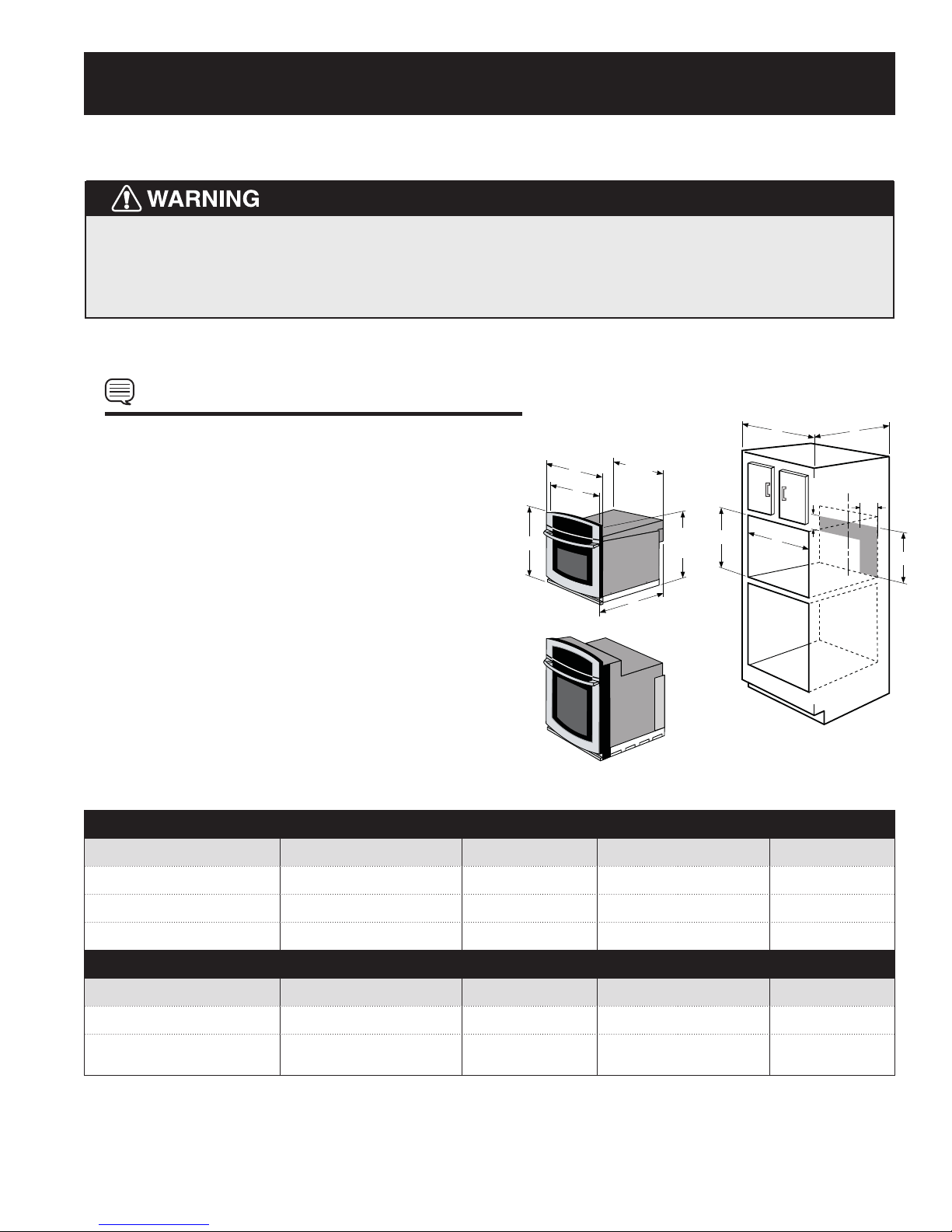
1. Base must be capable of supporting 150 pounds (68.0 kg) for
the Microwave Wall Oven only.
2. Make sure base is level and front of cabinet is square. If the
cabinet base is not level, the oven will tend to slide out when
23 ½"
A
C
(59.8 cm)
I
opening the door.
3. Minimum required distance is 36" (91.44 cm) from the floor.
B
(52.7 cm)
to top of
cp angle
F
20 ¾"
H
4. The outlet should not be located in the shaded area of Figure
1. It is required the outlet be a dedicated 120 volts with a
15amp rating for the appliance.
D
5. Minimum required distance between the Microwave Oven
and the wall oven cutouts should be at least 3 inches. The
actual visible space will be reduced due to the overlap of the
Microwave Oven lower vent and the wall oven.
Figure 1
PRODUCT DIMENSIONS
MODEL A B C D
EW27SO60LS 27" (68.8) 221/4" (56.5) 247/8" (63.2) 21
EW30SO60LS 30" (76.4) 221/4" (56.5) 28" (71.1) 21
E3OM075HSS / E3OM075HPS 30" (76.4) 22" (55.9) 28" (71.1) 21
4"
11
/16" (55.1)
11
/16" (55.1)
11
/16" (55.1)
G
C
L
6"
18"
MODEL Min. F Max. G Min. H Max. I
EW27SO60LS 251/8" (63.8) 255/8" (65.1) 24" (61.0) min. 21"(53) 211/2"(54.6) 27" (68.8) min.
EW30SO60LS /
E3OM075HSS / E3OM075HPS
All dimensions are in inches (cm).
281/2"(72.4) 29" (73.7) 24" (61.0) min. 21"(53) 211/2"(54.6) 301/8" (76.5) min.
CUTOUT DIMENSIONS AND CABINET WIDTH
E1
TINSLB032MRR0316902485
MICROWAVE WALL OVEN INSTALLATION INSTRUCTIONS
IMPORTANT NOTES TO
THE INSTALLER
1. Read all instructions contained in these installation
instructions before installing the Microwave Wall Oven.
This oven can be built into a cabinet or wall by itself or
above any electric wall oven or warming drawer.
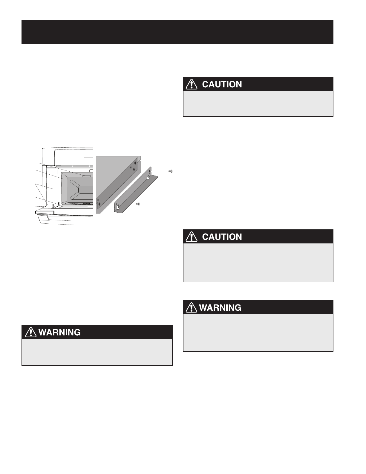
2. Remove all packing material from inside the oven cavity
before connecting the electrical supply to the Microwave
Wall Oven. DO NOT REMOVE THE WAVEGUIDE COVER,
which is located on the cavity ceiling. See Figure 2A.
Waveguide Cover
Oven Cavity
Door Seals
and Sealing
Surfaces
Hinge
Safety
Door Latch
IMPORTANT SAFETY
INSTRUCTIONS
Never use your appliance for warming or heating
the room. Prolonged use of the oven without adequate
ventilation can be dangerous.
Carpentry
Refer to Figure 1 for the dimensions required for your
appliance, and the space necessary to install the oven. The
oven support surface should be solid plywood or similar
material, the surface must be level from side to side and
from front to rear.
Electrical Requirements
The appliance operates on a 120 volt, 60 Hz electrical
supply with a separate ground wire. Provide a separate
circuit with a fuse or circuit breaker rated for 15 amps.
Observe all governing codes and local ordinances
Figure 2A Figure 2B
3. Remove the 2 shipping duct supports (see Figure 2B) by
removing the 2 screws securing each side. Reinsert 2
screws (each side) to secure the stainless cover.
4. Remove the feature sticker, if there is one, from the
outside of the door.
5. Check the oven for any damage, such as misaligned or
bent door, damaged door seals and sealling surfaces,
broken or loose door hinges and latches and dent
inside the cavity or on the door.
If there is any damage, DO NOT operate the
oven and contact your dealer or ELECTROLUX
AUTHORIZED SERVICER.
6. Observe all governing codes and local ordinances.
7. Be sure to leave these instructions with the consumer.
IMPORTANT NOTE TO
THE CONSUMER
Keep these instructions with your Owner's Guide for future
reference.
To prevent damage to the oven control, during cold
temperature weather, wait at least three (3) hours
after receiving this oven before supplying power to
the appliance. This will prevent possible damage to the
built-in oven control at power on.
Cabinet Installation
The Microwave Wall Oven can tip when the door
is open. The Anti-Tip brackets supplied with the
Microwave Wall Oven must be attached to the
cabinet and the appliance to prevent tipping of
the unit and injury to persons.
ANTI-TIP BRACKETS INSTALLATION
INSTRUCTIONS
1. Unpack the Microwave Wall Oven and find the 2
Anti-Tip brackets and screws included in the literature
package.
2. Install the Anti-Tip bracket in the cabinet as shown
on Figure 3. Note: To prevent damage to cabinet, it
is recommended to drill ¹/16" (0.16 cm) diameter pilot
holes before installing the Anti-Tip brackets.
E2
MICROWAVE WALL OVEN INSTALLATION INSTRUCTIONS
MICROWAVE WALL OVEN INSTALLATION
Two persons are required to install the oven. Never
hold the door handle when moving the oven.
3. Place the oven adjacent to the opening on a table or
stand. Plug the power supply cord into the electrical
outlet. Carefully guide the oven into the prepared
opening. Avoid pinching cord between oven and wall.
See Figure 4. Push the unit in and against the cabinet.
The oven side bracket will clip into the Anti-Tip brackets.
See Figure 3.
4. To pull out the oven for servicing, open the door and
locate the two holes on the side frame. Simultaneously
insert the tools provided with the appliance in both
holes and pull the oven towards you. See Figure 5.
ANTI-TIP BRACKET INSTALLATION
Cutout Width
(See dimensions below)
Anti-Tip Brackets
16-1/2"
(41.9 cm)
EW27SO60LS Cutout Width
25-1/8" (63.8 cm) Min.*
25-5/8" (65.1 cm) Max.*
25-3/8" (64.5 cm) Recommended*
EW30SO60LS / E3OM075HSS / E3OM075HPS Cutout Width
28-1/2" (72.4 cm) Min.*
29" (73.7 cm) Max.*
28-3/4" (73.0 cm) Recommended*
Cutout Height
21" (53.3 cm) Min.*
21-1/2" (54.6 cm) Max.*
Figure 3
FINISHED ANTI-TIP BRACKET INSTALLATION
REMOVING OVEN FOR SERVICING
Anti-Tip Bracket
Oven
Bracket
installed in cabinet
Oven
Cabinet
Right Side
Tool supplied
Anti-Tip
Bracket
released
Oven removed
from the cabinet
Figure 4
Figure 5
E3
MICROWAVE WALL OVEN INSTALLATION INSTRUCTIONS
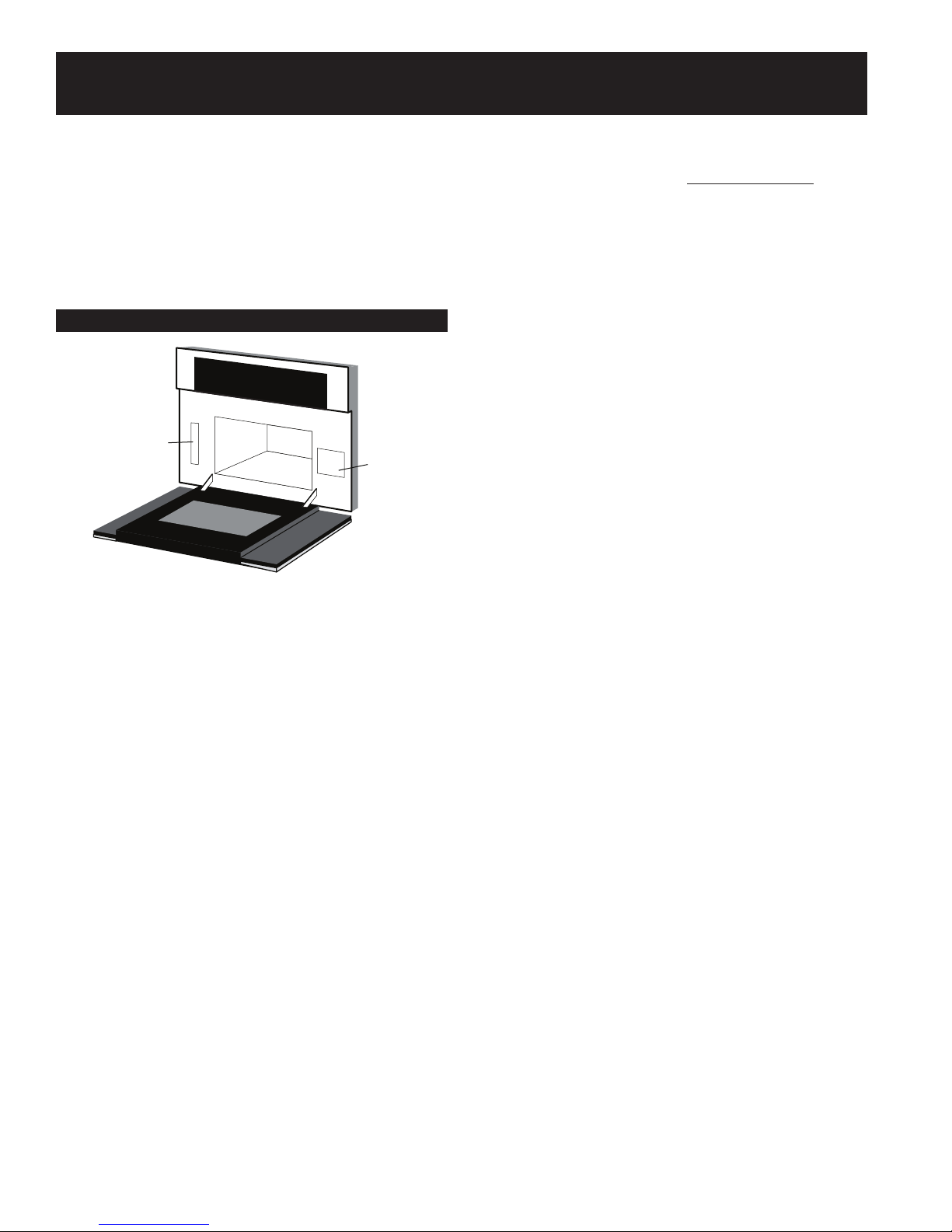
Model and Serial Number Location
The serial plate is located on the oven front frame. See
Figure 6.
When ordering parts for or making inquires about your
oven, always be sure to include the model and serial
numbers and a lot number or letter from the serial plate on
your oven.
PRODUCT IDENTIFICATION
Serial
Plate
Figure 6
Menu
Label
Before You Call for Service
Refer to the warranty in your Use & Care Guide for our
toll-free service number and address. Please call or write
if you have inquiries about your product and/or need to
order parts.
E4
 Loading...