

Page 1
Model EOU 6365
Page 2

2
These warnings are provided in the interests of your safety. Ensure that you understand them all before installing
or using the appliance. Your safety is of paramount importance. If you are unsure about any of the meanings of
these warnings contact the Customer Care Department. The address is on the back page of this book.
INSTALLATION
The appliance must be installed according to the
instructions supplied. The installation work must
be undertaken by a qualified electrician/competent
person.
The appliance must be installed in an adequately
ventilated room.
NOTE: It is imperative that the appliance is left in
the base to protect both the appliance and the
floor.
This appliance is heavy and care must be taken
when moving it. Do not try to lift or move the
appliance by pulling the door handles.
Warning: Do Not attempt to lift this appliance by
the handles.
All packaging, both inside and outside the
appliance must be removed before the appliance
is used.
It is dangerous to alter the specifications or
modify the appliance in any way.
After installation please dispose of the packaging
with due regard for safety and the environment.
Your local authority can arrange this.
CHILD SAFETY
Do not allow young children to play with any part
of the packaging.
This appliance is designed to be operated by
adults. Young children must not be allowed to
tamper with the controls or play near or with the
appliance.
CAUTION: Accessible parts may be hot when
the grill is in use. Young children should be
kept away.
DURING USE
This appliance is not intended to be operated by
means of an external timer or separate remote
control system.
This appliance has been designed for domestic
use to cook edible foodstuffs only, and must not
be used for any other purposes.
Take great care when heating fats and oils as
they will ignite if they become too hot.
Never place plastic or any other material which
may melt in or on the oven.
Do not stand too close to the oven or grill while
in use as warm air will exhaust from the grill
cavity and the vents on the front frame of the
appliance.
Do not leave the grill pan handle in position
when grilling and ensure oven gloves are used to
remove and replace the handle, as it will become
hot.
Always use oven gloves to remove and place
food in the oven.
Ensure that all vents are left unobstructed to
ensure ventilation of the oven cavity.
Never line any part of the appliance with foil.
Stand clear when opening the drop down oven
doors. Support the doors using the handles until
fully open.
Never leave the appliance unattended when
the oven door is open.
Do not place sealed cans or aerosols inside the
oven. They may explode if they are heated.
Ensure that all control knobs are in the OFF
position when not in use.
Do not stand on the appliance or on the open
oven doors.
Do not hang towels, dishcloths or clothes from
the appliance or its handles. They are a safety
hazard.
CLEANING AND MAINTENANCE
The appliance is heavy and care must be taken
when moving it.
For hygiene and safety reasons this
appliance should be kept clean at all times. A
build-up of fats or other foodstuffs could
result in a fire especially in the grill pan.
Do not leave cookware containing foodstuffs,
e.g. fat or oil in the appliance in case it is
inadvertently switched on.
Always allow the cooling fan to cool the
appliance down before switching off at the wall
prior to carrying out any cleaning / maintenance
work.
Only clean this appliance in accordance with the
instructions given in this book.
SERVICE
Repairs should not be carried out by
inexperienced persons as this may cause injury
or serious malfunction. This appliance should be
serviced by an authorised Service Engineer and
only genuine approved spare parts should be
used. Details of servicing and repair
arrangements are supplied on page 31 of this
book.
AT THE END OF THE APPLIANCE'S LIFE
When the time comes to dispose of your
appliance please contact your local Council
Authority. They can arrange to dispose of the
appliance in a safe and controlled manner. The
number will be in the telephone book.
Please read the
instruction book carefully
before use and retain for
future reference.
IMPORTANT SAFETY INFORMATION
Page 3

3
FOR THE USER
Important Safety Information 2
Description Of The Appliance 4
Getting To Know Your Appliance 5
The Cooling Fan For The Controls 6
Control Panel Indicator Neons 6
Before Using The Appliance 7
When First Switching On 7
Rating Plate 7
Preparing To Use Your Appliance 7
Condensation And Steam 7
Cookware 8
Grill And Oven Furniture 8
The Timer 9
The Dual Grill 12
Uses Of The Dual Grill 12
How To Use The Dual Grill 12
Things To Note 12
To Fit The Grill Shelf 12
The Grill Pan and Handle 13
Hints And Tips 13
Grilling Chart 15
The Top Oven 16
Uses Of The Top Oven 16
How To Use The Top Oven 16
Things To Note 16
To Fit The Top Oven Shelf 16
Hints And Tips 17
Top Oven Cooking Chart 18
The Main Oven 19
Uses Of The Main Oven 19
Preheating 19
Cooking Temperatures 19
Batch Baking 19
How To Use The Main Oven 19
Things To Note 19
To Fit The Main Oven Shelves 20
Hints And Tips 20
Main Fan Oven Cooking Chart 21
Roasting Chart 22
Defrost Feature 23
Uses Of Defrost Feature 23
How To Defrost 23
Things To Note 23
Hints And Tips 23
Care and Cleaning 24
Cleaning Materials 24
Cleaning The Outside Of The Appliance 24
Cleaning The Controls Knobs And Handles 24
Cleaning Inside The Oven And Grill
Compartments 24
Care Of Stayclean Surfaces 25
Hints And Tips 25
Cleaning The Top Oven Roof 26
Cleaning The Outer And Inner Door
Glass Panels 26
To Remove The Outer Glass 27
To Replace The Outer Door Glass 27
To Clean The Inner Glass Door 28
To Remove The Wirework Runners 28
Cleaning The Shelves, Wirework Runners And
Grill/Oven Furniture 28
Replacing An Oven Light Bulb 28
Something Not Working 29
Service and Spare Parts 31
Guarantee Conditions 32
FOR THE INSTALLER
Technical Details 33
Warnings 34
Choice Of Electrical Connection 34
Things To Note 35
Preparing Cabinet For Fitting Of Oven 36
How To Finish Unpacking 37
Making The Electrical Connections 38
To Remove Cover Of Mains Terminal 38
Connecting To The Mains Terminal 39
Checking Electrical Connections 40
Connecting To A Hob Or Cooker Point 40
Fitting Into The Space Between Cabinets 41
Notes 42
To help you the following symbols will be found in the
text.
Hints and Tips
Safety Instructions
CONTENTS
Page 4
4
Built in electric oven and grill
WARNING: THIS APPLIANCE MUST BE EARTHED
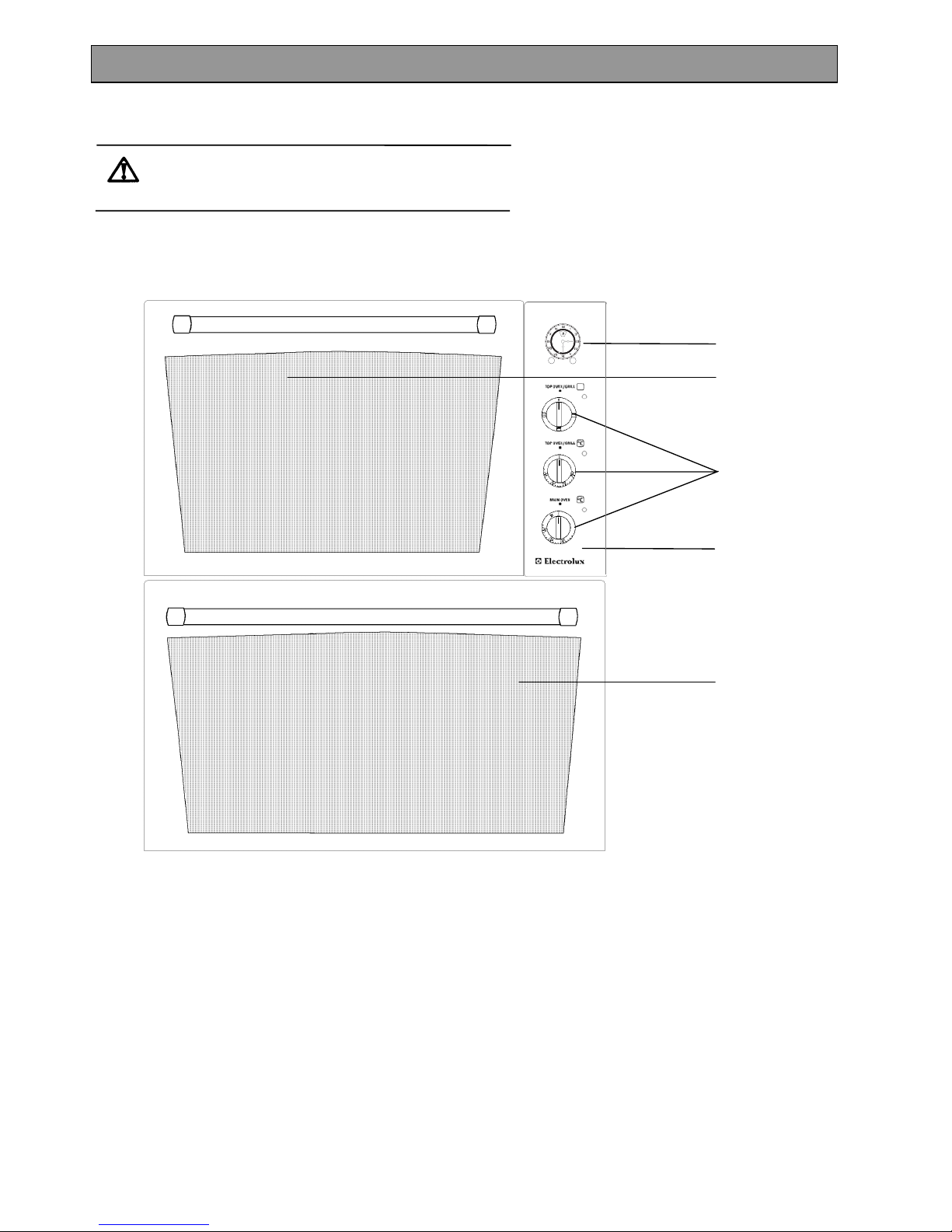
Your built-in appliance comprises of an electric oven and grill.
The main fan oven is the larger of the two ovens. It is particularly suitable for cooking larger quantities of food.
The oven can be automatically controlled by the electronic timer.
DESCRIPTION OF THE APPLIANCE
Oven
Timer
Grill/ Top Oven
Control Panel
Control Knobs
Page 5
5
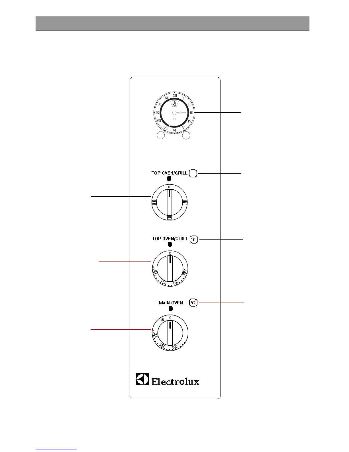
The Control Panel
GETTING TO KNOW YOUR APPLIANCE
Electronic Timer
Main oven Indicator Neon
Main Oven Temperature
Control
Top Oven/Grill Selector Neon
Top Oven/Grill Temperature
Control
Top Oven/Grill Selector
Top Oven/Grill Indicator Neon
Page 6
6
THE COOLING FAN FOR THE CONTROLS
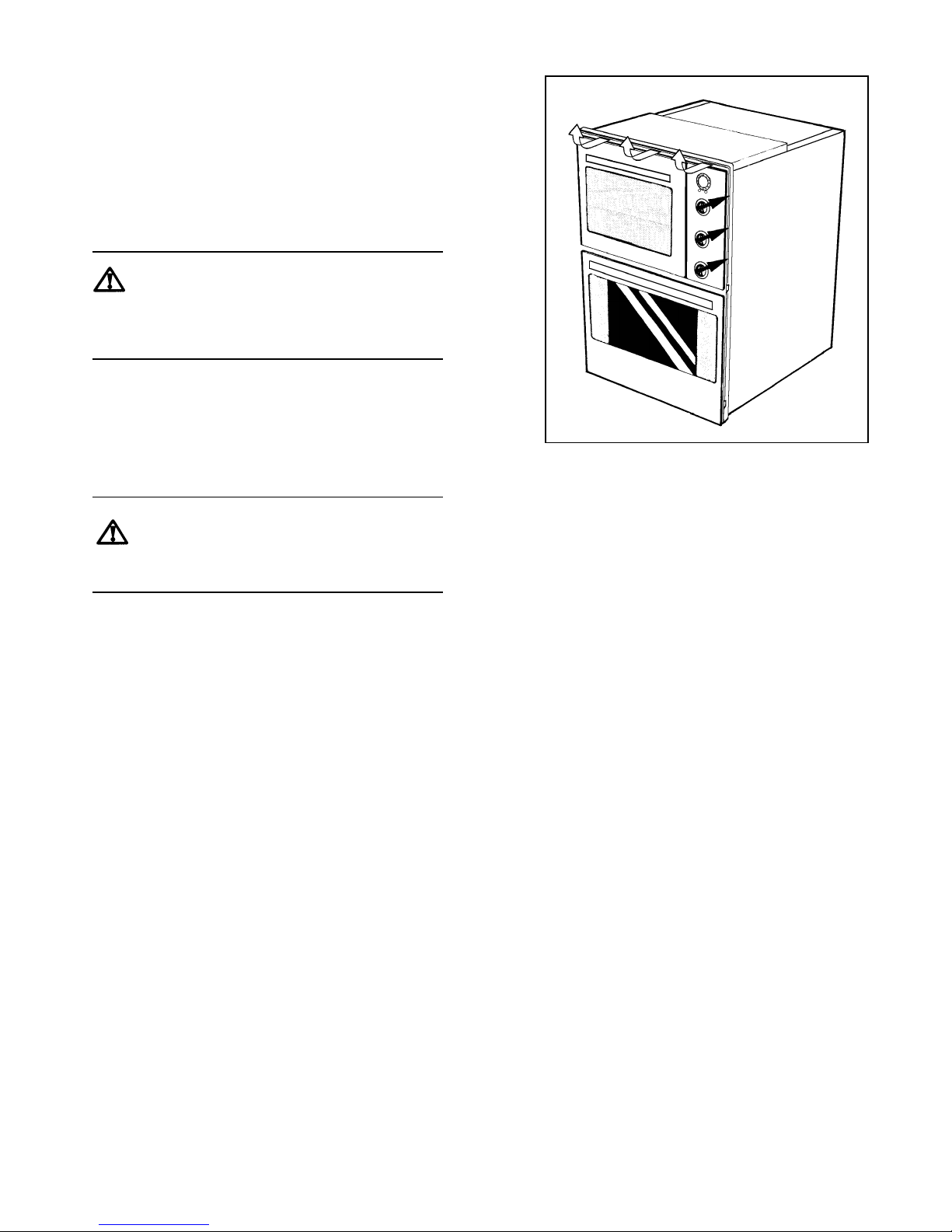
Your appliance has a cooling fan fitted behind the
controls to prevent them from overheating.
The cooling fan will come on immediately when the
grill is switched on and after a short time when the
oven is in use.
The cooling fan may run on after the oven or grill is
turned off for a period of time to cool the appliance
down. It may continue to switch on and off until the
appliance is cool.
Always allow the cooling fan to cool the
appliance down before switching off at the
wall prior to carrying out any cleaning or
maintenance work.
NOTE:
The action of the cooling fan will depend on how long
the oven or grill have been used and at what
temperature. It may not run on where the grill or
oven has only been used for a short time.
Do not stand too close to the grill or oven
when in use as warm air will exhaust from
the grill cavity and oven vents.
CONTROL PANEL INDICATOR NEONS
These lights indicate whether the ovens are switched
on. They will turn on and off during use to show that
the temperature is being maintained.
The Main Oven neon does not operate with the
Defrost setting.
If the neons do not operate as the instructions
indicate the control has been incorrectly set.
Return all controls to zero and re-set following the
instructions for the required setting.
Page 7
7
WHEN FIRST SWITCHING ON
The timer must be set to manual operation before the
fan oven can be operated. For instructions on how to
set the timer see page 9.
If the Main Oven indicator neon does not glow when
the oven is switched on, it is most likely that the timer
is set for automatic cooking.
The Grill is not controlled by the electronic timer.
RATING PLATE
This is situated on the lower front frame of the
appliance upon opening the door. Alternatively the
rating plate may also be found on the back or top of
some models (where applicable).
The appliance must be protected by a suitably rated
fuse or circuit breaker. The rating of the appliance is
given on the rating plate.
Do not remove the rating plate from the appliance
as this may invalidate the guarantee.
PREPARING TO USE YOUR APPLIANCE
Wipe over the base of the oven with a soft cloth and
hot soapy water and wash the grill and oven furniture
before use.
We suggest that you run the oven elements for 10 –
15 minutes at 220°C to burn off any residue from
their surfaces.
The procedure should be repeated with the grill for
approximately 5 – 10 minutes.
During this period and odour may be emitted, it is
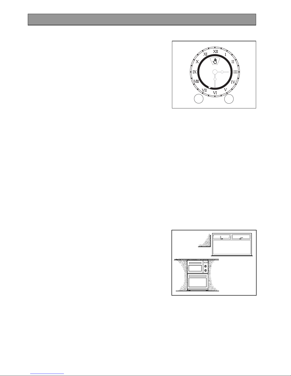
therefore advisable to open a window for ventilation.
CONDENSATION AND STEAM
When food is heated it produces steam in the same
way as a boiling kettle does. The ovens are vented
to allow some of this steam to escape. However,
always stand back from the appliance when opening
the oven doors to allow any build up of steam or heat
to be released. If the steam comes into contact with
a cool surface on the outside of the appliance, e.g. a
trim, it will condense and produce water droplets.
This is quite normal and is not caused by a fault on
the appliance.
To prevent discolouration occurring, regularly wipe
away condensation and any soilage from the
appliance surfaces.
BEFORE USING THE APPLIANCE
Page 8
8
COOKWARE
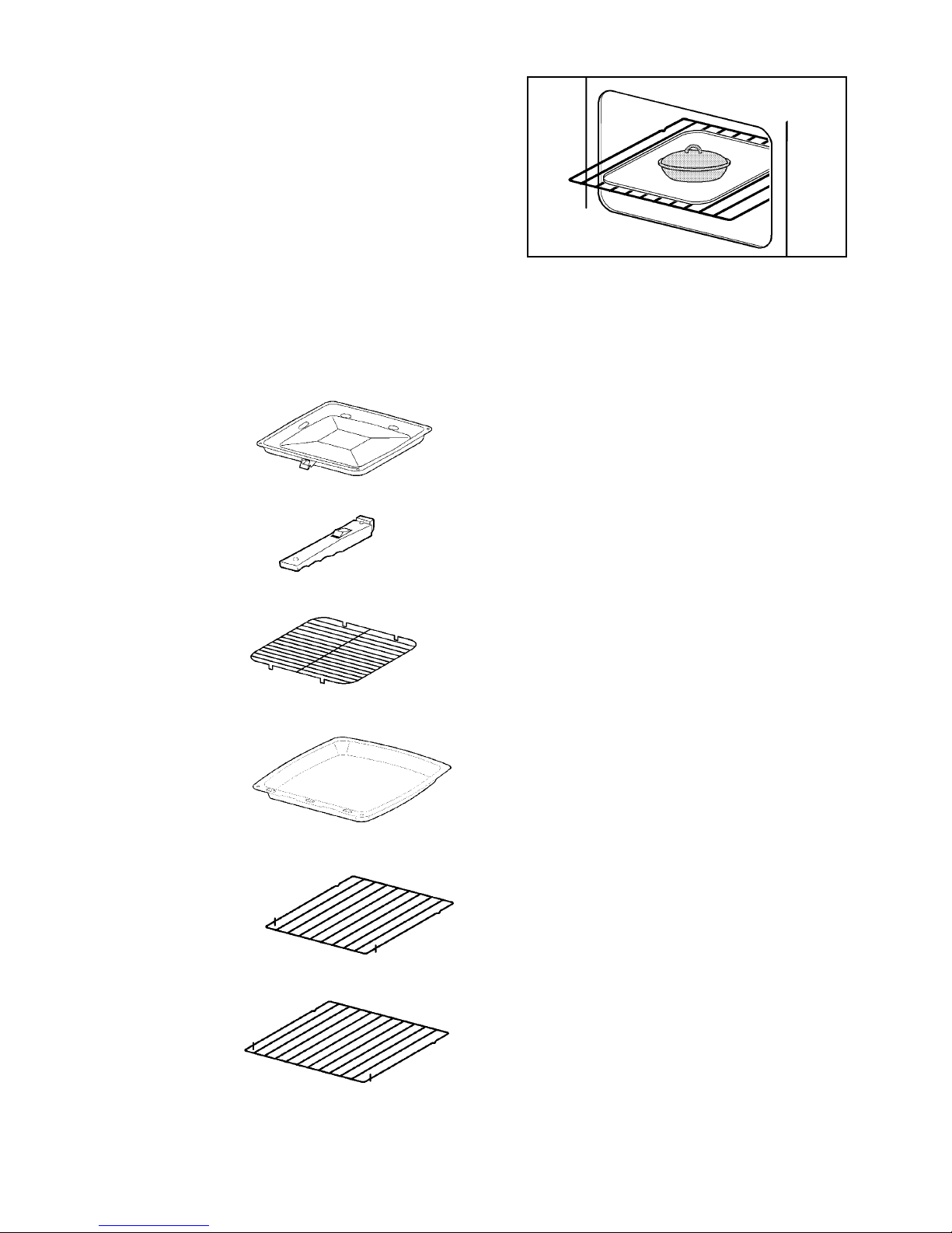
Baking trays, oven dishes etc., should not be placed
directly against the grid covering the fan at the back
of the oven.
Do not use baking trays larger than 30cm x 35cm
(12” x 14”) as they will restrict the circulation of heat
and may affect performance.
Advice on the effect of different materials and
finishes of bakeware is given in ‘Hints and Tips’ in the
appropriate oven section.
GRILL AND OVEN FURNITURE
The following items of oven furniture have been
supplied with the appliance:
1 grill pan
1 grill pan handle
1 grill pan grid
1 meat tin
1 shelf for grilling and
top oven cooking only
2 shelves for main
oven cooking
Page 9
9
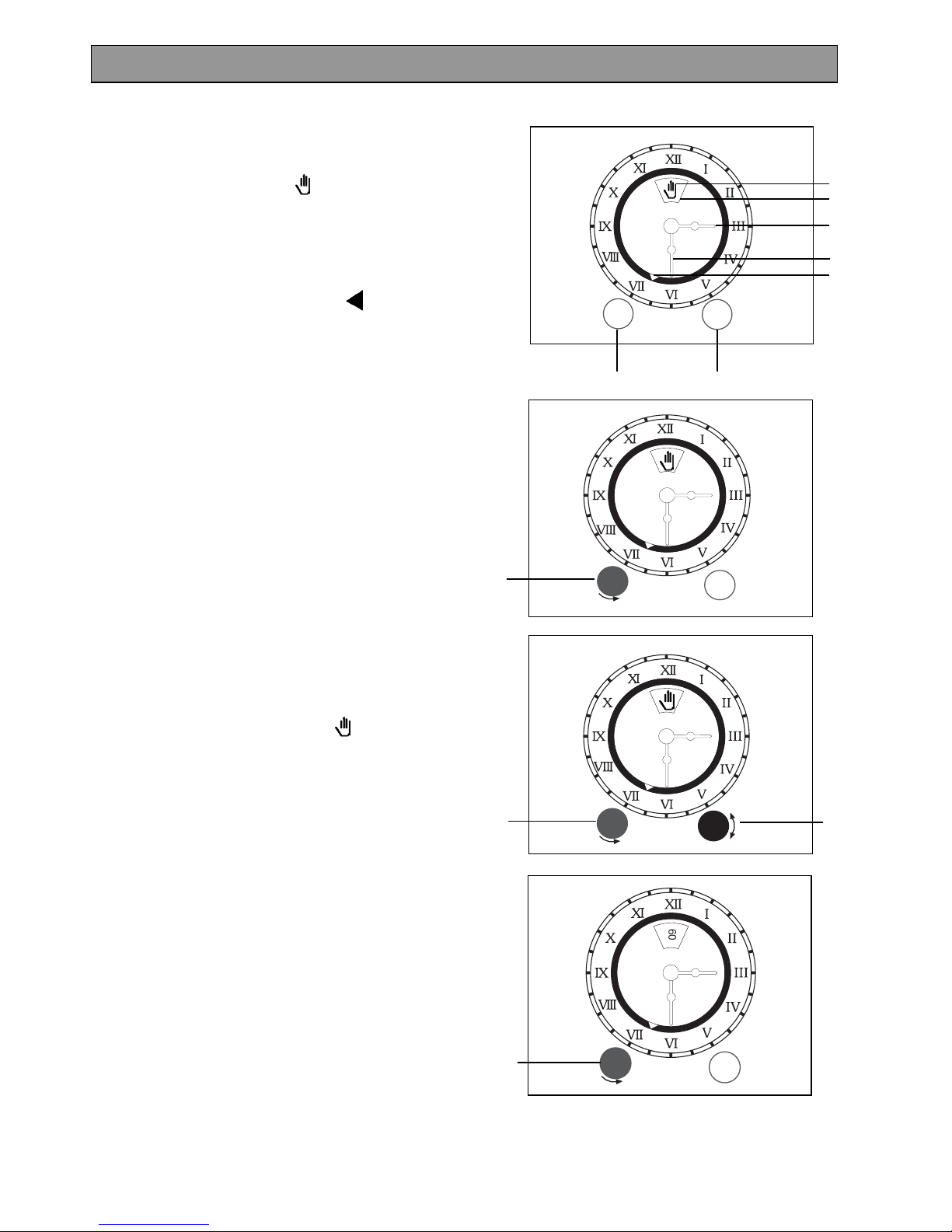
A CLOCK/COOK TIME SETTING KNOB
B START TIME SETTING KNOB
C MANUAL SYMBOL ( )
D DISPLAY WINDOW
E HOUR HAND
F MINUTE HAND
G START TIME INDICATOR ( )
1. TO SET THE TIME OF DAY
The clock will operate when the appliance is
switched ON at the wall.
To set, push in and turn setting knob (A) anticlockwise until the right time of day is displayed,
e.g. 7 a.m. as Fig.1.
2. TO SET TO MANUAL
Ensure the time of day has been set as above.
Push in and turn setting knob (B) in either
direction until the start time indicator (G) lines up
with the hour hand of the clock.
Turn setting knob (A) anti-clockwise, without
pushing it in until the manual ( ) symbol can
be seen in the display window as Fig. 2.
The oven temperature controls can now be
operated as required. The oven indicator neon
will glow.
3. TO SET THE MINUTE MINDER
Turn setting knob (A) anti-clockwise, without
pushing it in. The selected minutes can be
seen in the display window, e.g. 60 minutes as
Fig. 3.
A period of up to 180 minutes (3 hours) can be
timed using the minute minder. The minute
minder cannot be used when an automatic
programme has been set on the oven timer.
At the end of the set time a continuous bell will
sound for up to 6 minutes. The oven will turn off.
THE TIMER
60
Fig. 3.
A
F
A
B
C
D
E
G
Fig. 1.
A
Fig. 2.
A
B
Page 10
10
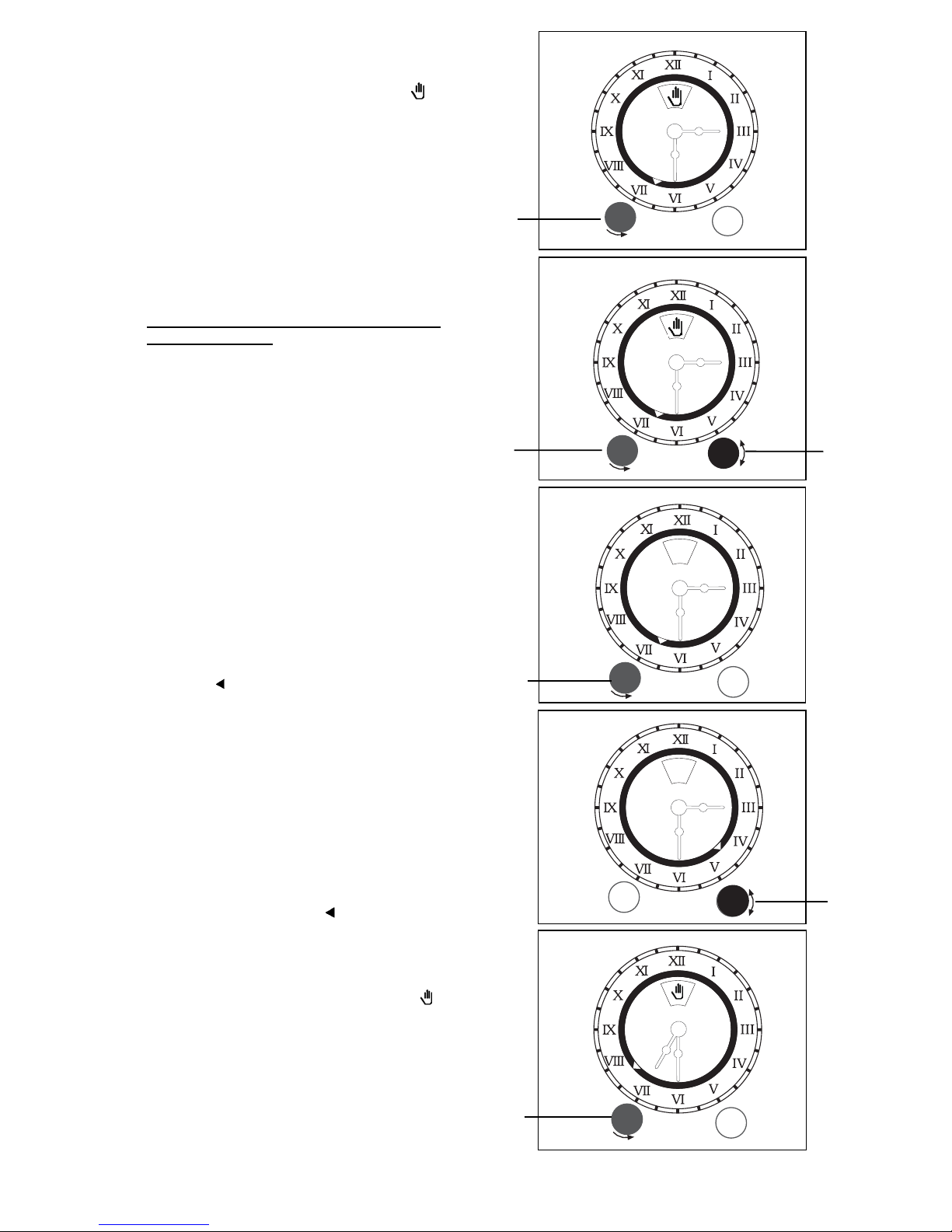
4. TO CANCEL THE MINUTE MINDER
Turn setting knob (A) anti-clockwise, without
pushing it in until the manual symbol ( )
appears in the display window as Fig.4.
5. HOW TO SET THE OVEN TIMER
When using the oven timer for the very first time,
it is advisable to let it operate while you are at
home. The timer can be checked to show that it
is operating correctly, you will then feel confident
to leave a meal to cook automatically in the
future.
A) TO SWITCH THE OVEN ON AND OFF
AUTOMATICALLY
i) Make sure the electricity supply is switched
ON.
ii) Ensure the clock shows the correct time of
day and the appliance is set in manual (see
point 2).
Adjust as necessary as Fig. 5.
iii) Place food in oven.
iv) To set the length of time you want the food to
cook; turn setting knob (A) anti-clockwise,
without pushing it in, until the required
cooking period can be seen in the display
window e.g. 165 minutes (2 hours 45 mins)
as Fig. 6.
v) Set the start time, by pushing in and turning
setting knob (B) in either direction until
indicator ( ) (G) lines up with the time you
want the food to start cooking, e.g. 4.30 p.m.
as Fig.7.
vi) Turn the oven temperature control to the
required setting. The oven indicator light
should be OFF.
vii) When automatic cooking starts the oven
indicator neon will remain on whilst reaching
temperature and will then turn ON and OFF
showing that the oven temperature is being
maintained.
viii) The start time indicator ( ) (G) will move
with the hour hand of the clock until the
length of cooking time is complete. A bell will
sound which can be cancelled by turning
setting knob (A) anti-clockwise without
pushing it in, until manual symbol ( )
appears in the display window as Fig.8.
ix) The maximum cooking time on automatic is
180 minutes (3 hours).
60
60
165
Fig.6
A
60
60
Fig.8
A
Fig.7
B
60
60
165
Fig. 5.
A
B
Fig. 4.
A
Page 11
11
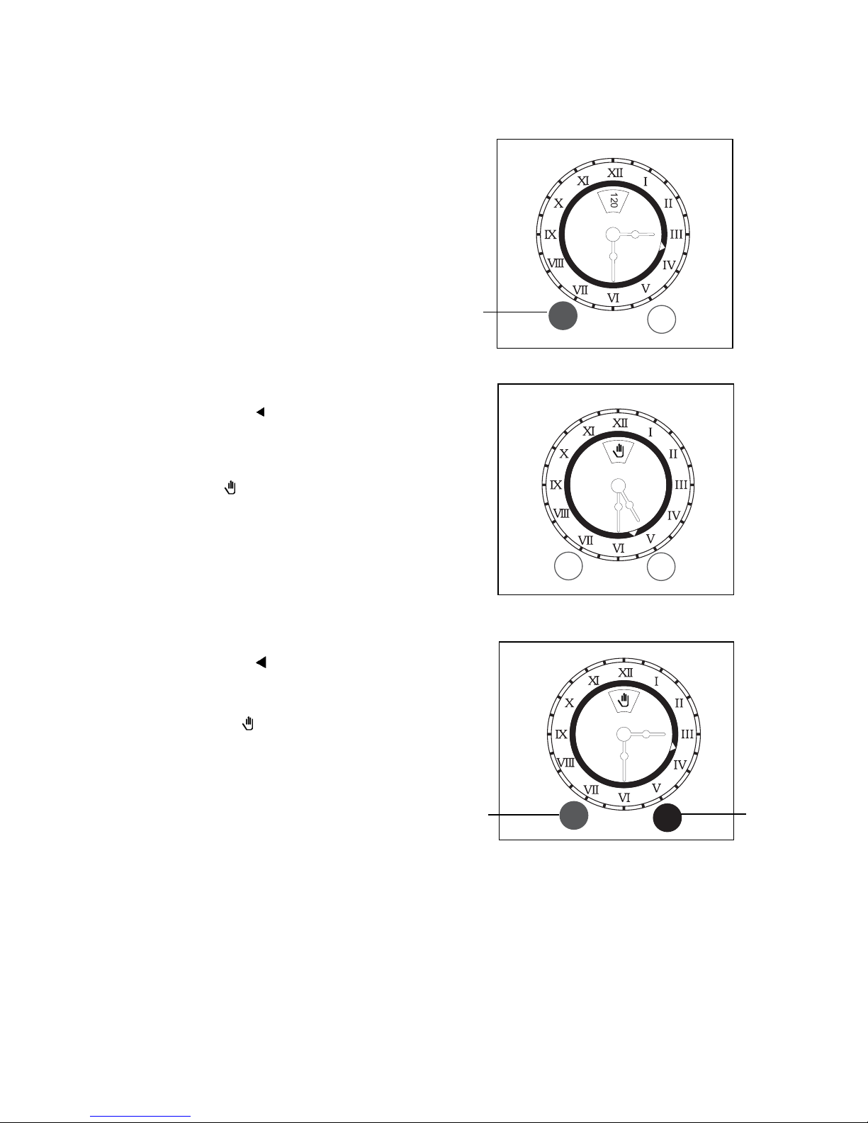
B) TO SET THE TIMER TO SWITCH OFF
AUTOMATICALLY
i) Make sure the electricity supply is switched on.
ii) Ensure the clock shows the correct time of day
and the appliance is set to manual. Adjust as
necessary.
iii) Place food in oven.
iv) To set the length of time you want the food to
cook; turn setting knob (A) anti-clockwise,
without pushing it in, until the required cooking
period can be seen in the display window, e.g.
120 minutes (2 hours) as Fig. 9.
v) Turn the oven temperature control to the required
setting. The oven indicator neon should glow.
vi) The oven indicator neon will remain on whilst
reaching temperature and will turn ON and OFF
showing that the oven temperature is being
maintained.
vii) The start time indicator ( ) (G) will move with the
hour hand of the clock until the length of cooking
time is complete. A bell will sound which can be
cancelled by turning setting knob (A) anticlockwise, without pushing it in, until the
manual symbol ( ) appears in the display
window as Fig. 10.
6. RETURNING THE APPLIANCE TO
MANUAL OR TO CANCEL AN
AUTOMATIC PROGRAMME
Turn the oven temperature control OFF. Ensure
the start time indicator ( ) (G) lines up with the
hour hand of the clock by pushing in and turning
in either direction, setting knob (B) Fig 11.
The manual symbol ( ) should be displayed in
the window by turning setting knob (A) anticlockwise, without pushing it in.
Turn the oven temperature control ON to check
that the oven operates manually. The oven neon
indicator neon should glow.
7. THINGS TO NOTE
If an automatic programme has been set on the
main oven, the grill WILL operate manually.
The delay time plus the cooking time MUST NOT
exceed 11 hours and 59 minutes.
Fig.10
Fig.11
A
B
Fig.9
A
120
Page 12
12
WARNING – Accessible parts become hot
when the grill is in use. Keep children
away.
USES OF THE DUAL GRILL
The grill is situated in the Top Oven compartment.
The grill is a dual circuit grill which means that the full
area of the grill or the centre section only can be
used. Use the full grill for cooking larger quantities of
food. Use the centre section for economy purposes
when cooking smaller quantities.
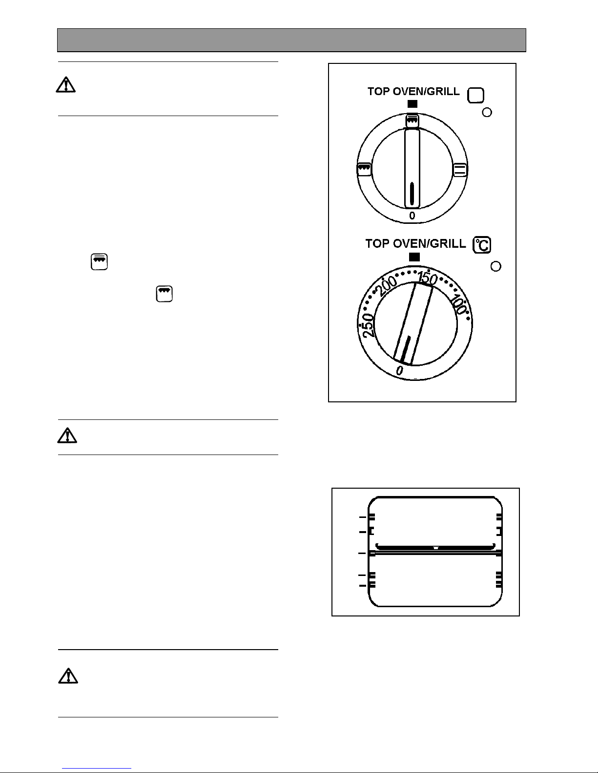
HOW TO USE THE DUAL GRILL
1. Select the Top Oven/Grill Selector to Full for full
grill.
2. Select the Top Oven/Grill Selector to Half for
centre section only.
3. Turn the Top Oven/Grill Temperature control knob
to the right as far as it will go. This is the hottest
setting.
4. To use the grill at lower settings, turn the Top
Oven/Grill Temperature control knob to 100°C or
150°C.
THINGS TO NOTE
The grill door must be left open when
grilling.
· The top oven interior light will come on.
· The cooling fan for the controls will operate as
soon as the grill control is turned. For more
information on the operation of the cooling fan
turn to page 6.
· The outer section of the grill element may appear
to glow brighter than the inner section. This is
quite normal.
· The top oven/grill selector neon will illuminate.
· We recommend using the grill pan on the shelf in
positions 3 or 5.
· If you use the grill pan in position 3 the shelf must
be withdrawn before the pan can be located or
removed.
If you use the grill pan in position 3 the
shelf must be withdrawn before the pan can
be located or removed.
Ensure the grill pan is properly located.
THE DUAL GRILL
5
4
3
2
1
Page 13
13
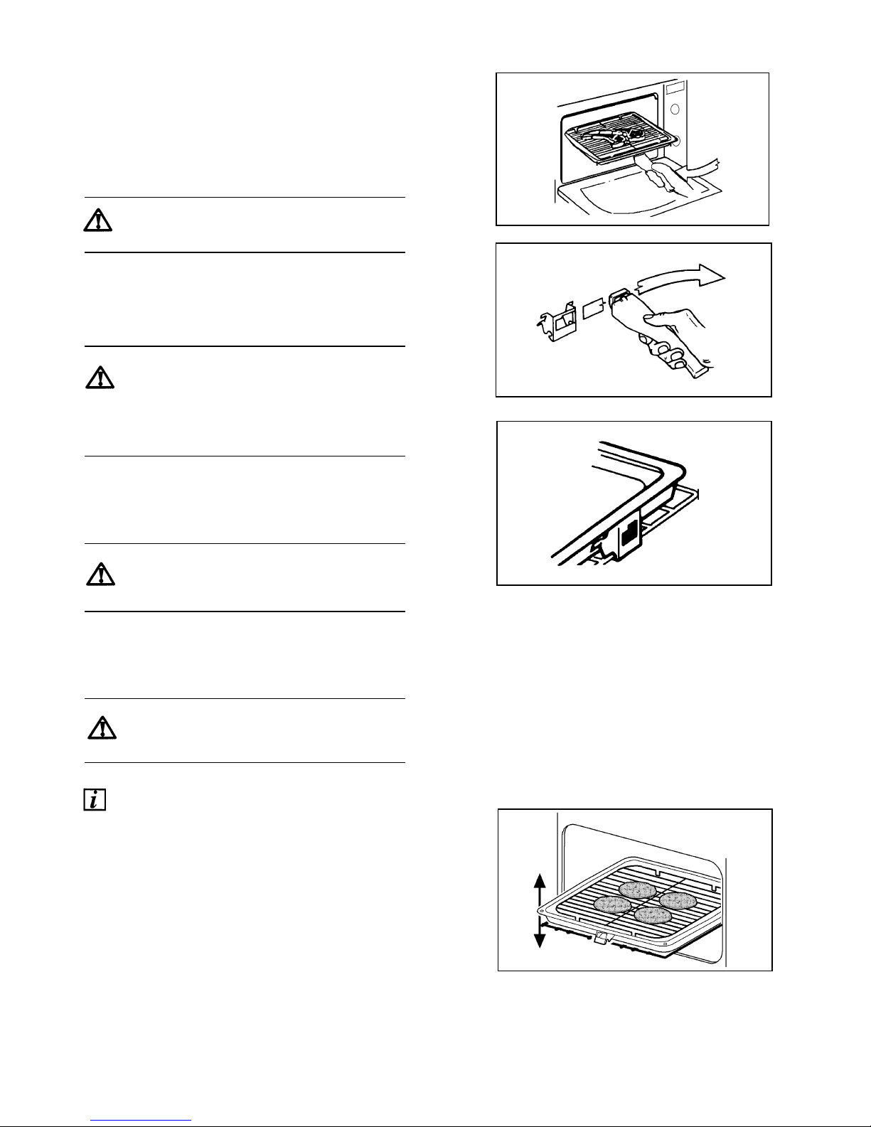
THE GRILL PAN AND HANDLE
The grill pan has a removable handle.
To insert the handle, press the button on the handle
with the thumb and pivot the handle slightly upwards
inserting the lip into the widest part of the bracket.
Move the handle towards the left, lower into position
and release the button.
Ensure the handle is positively located.
To remove the handle, press the button on the
handle with the thumb and pivot the handle slightly
upwards and towards the right to remove from the
bracket.
Protect your hands when removing the grill
pan handle.
Always remove the grill pan handle during
grilling.
To correctly locate the grill pan on the shelf, ensure
that the cut out on the underside of the handle
bracket locates over the front bar of the shelf.
The Grill Pan must not be located in the
shelf runners.
To check the progress of the food being grilled, the
grill pan should be withdrawn on the shelf to attend to
food during cooking.
Ensure that you support the grill pan when
it is withdrawn.
HINTS AND TIPS
· Most foods should be placed on the grilling grid
in the grill pan. This allows maximum circulation
of air by raising the food out of fats and juices.
· Adjust the grid and grill pan runner to allow for
different thicknesses of food. Position the food
close to the element for faster cooking and
further away for more gentle cooking.
Page 14
14
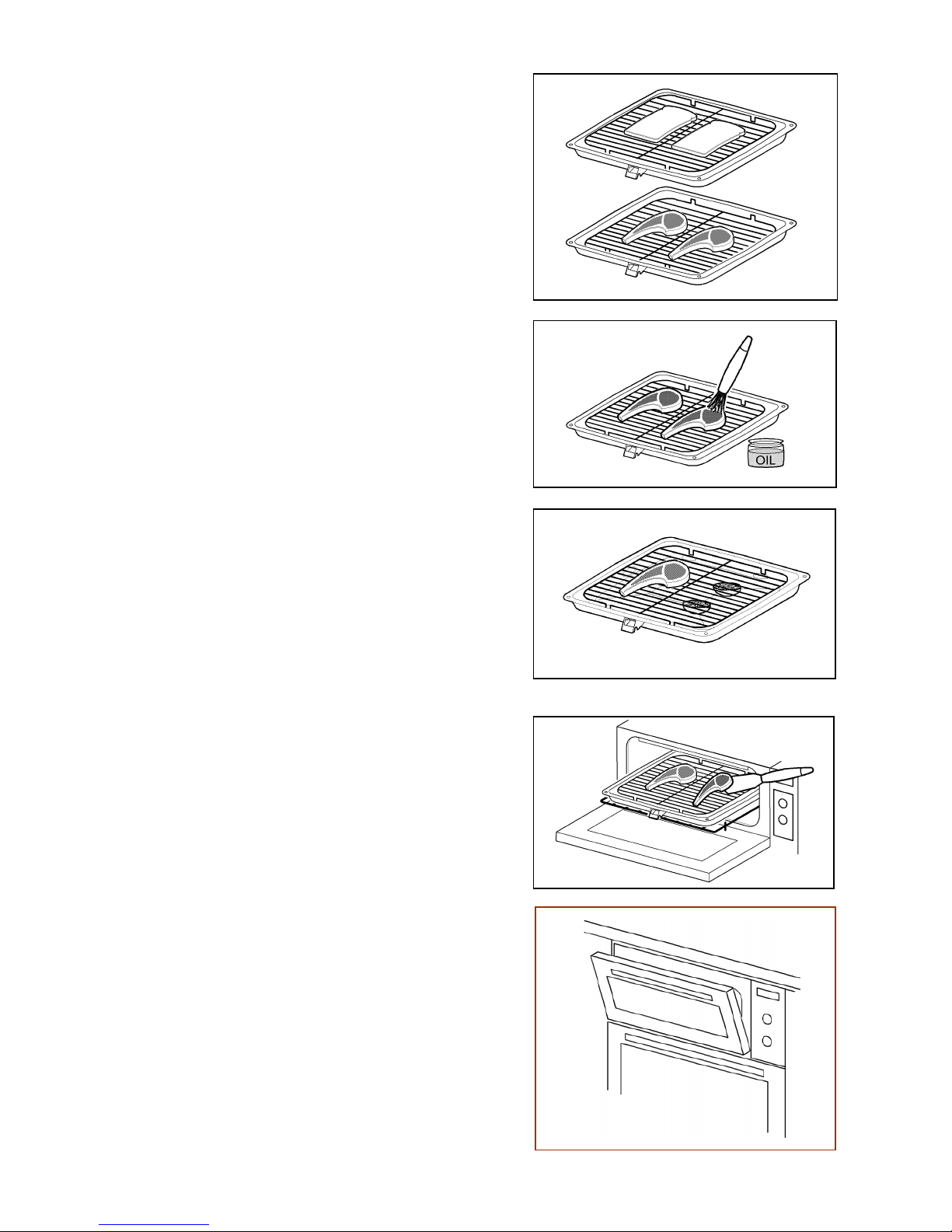
· The grill pan grid is reversible. This is useful if
you want to cook foods of varying thicknesses.
As a general rule, bread for toasting should be
placed on the grid in the ‘high’ position in the grill
pan. Foods such as chicken pieces or chops
may be grilled using the grilling grid in the low
position.
· Food should be thoroughly dried before grilling to
minimise splashing. Brush lean meats and fish
lightly with a little oil or melted butter to keep
them moist during cooking.
· Accompaniments such as tomatoes and
mushrooms may be placed underneath the grid
when grilling meats.
· The food should be turned over during cooking
as required. Do not use the grill to keep food
warm as it will continue to cook the food.
· The grill door must be left open when grilling.
For convenience the grill door can be left ajar.
· Preheat the grill on full setting for a few minutes
before sealing steaks or toasting. Adjust the heat
setting and the shelf position as necessary during
cooking.
Page 15

15
The chart below gives recommended cooking times and shelf positions. Remember that these are a guide and
should be adjusted to suit personal taste.
Note: Shelf positions are counted from the bottom upwards.
FOOD GRILL TIME
(Min)
Shelf Grid
Position
Bacon Rashers 3 – 5 each side 5 High
Beefburgers 6 – 10 each side 5 Low
Chicken Joints 15 – 20 each side 3 High
Chops – Lamb 7 – 10 each side 5 Low
Pork 10 – 15 each side 5 Low
Fish – Whole / Herring 8 – 12 each side 5 Low
Fillets – Plaice / Cod 4 – 6 each side 5 Low
Kebabs 10 – 15 each side 5 Low
Kidneys – Lamb 4 – 6 each side 5 Low
Pig 8 – 10 each side 5 Low
Liver – Lamb/Pig 5 – 10 each side 5 Low
Sausages 10 –15 turn as required 5 Low
Steaks – Rare 3 – 6 each side 5 Low
Medium 6 – 8 each side 5 Low
Well Done 7 – 10 each side 5 Low
Browning e.g. au gratin, 3 – 5 mins 3 Lasagne, Shepherd’s Pie
GRILLING CHART
Page 16
16
USES OF THE TOP OVEN
The Top oven is the smaller of the two ovens.
The Top oven is a conventional oven, i.e. without a
fan. It is convenient where smaller quantities or
convenience foods are being cooked. It is important
to refer to the cooking chart as a guide to shelf
positions and temperatures as these may differ from
previous cookers you may have used.
HOW TO USE THE TOP OVEN
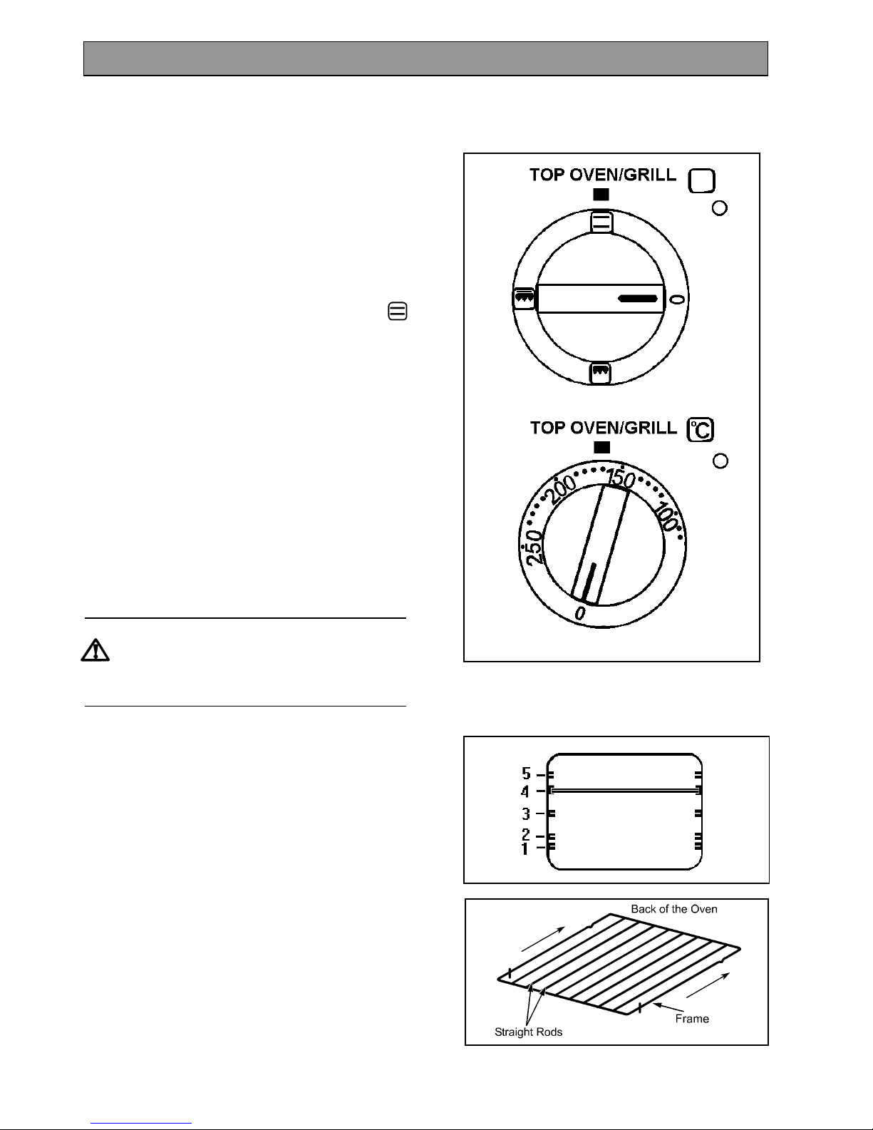
1. Turn the Top Oven/Grill Selector to Top Oven.
2. Turn the Top Oven temperature control to the
required setting.
THINGS TO NOTE
· The Top Oven interior light will come on.
· The Top Oven/Grill selector neon will illuminate.
The Top Oven temperature neon will illuminate
until the oven has reached the desired
temperature and then go out. It will turn on and
off periodically during cooking showing that the
temperature is being maintained.
· The cooling fan for the controls will operate after
a time. See page 6 for more information on the
operation of the cooling fan.
Do not place dishes, tins and trays directly
on the oven base as it becomes very hot and
damage will occur.
TO FIT THE TOP OVEN SHELF
There are 5 shelf positions in the Top Oven.
Shelf positions are counted from the bottom upwards.
The shelf should be fitted with the straight rods
uppermost on the frame and the forms towards the
back of the oven.
If not fitted correctly the anti-tilt and safety stop
mechanism will be affected.
THE TOP OVEN
Page 17
17
HINTS AND TIPS
· Use the Top Oven when you want to warm
plates. Use the lowest setting on the top oven
temperature control.
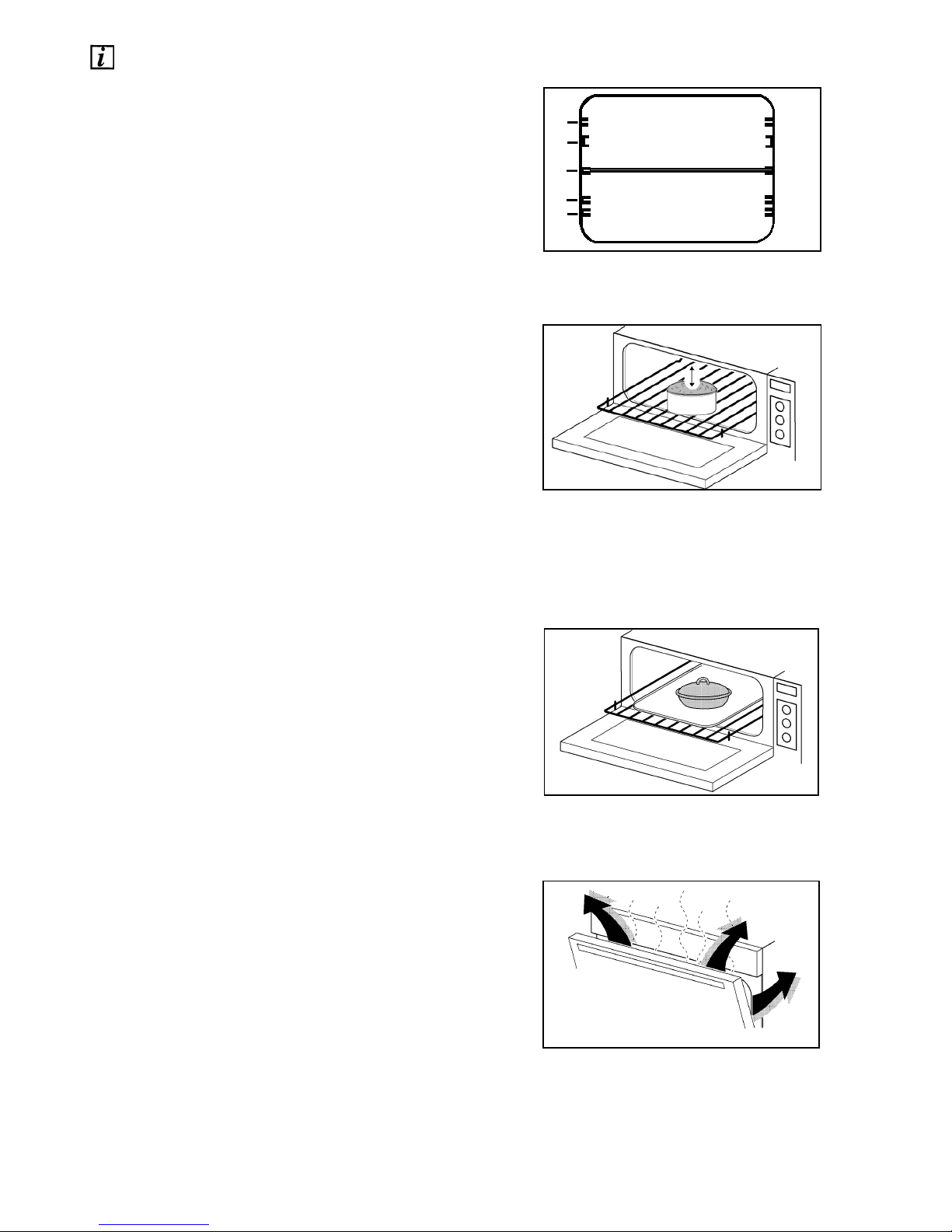
· You can only cook on one shelf when using the
Top Oven. For the best results food should be
placed in the centre of the oven. To increase top
browning e.g. for au gratin dishes, the food
should be placed towards the top of the oven.
Similarly for foods which benefit from the base
been browned, e.g. pizza, quiches and flans
place the food on a lower shelf.
· There should always be at least 2.5cm (1”)
between the top of the food and the grill element.
This gives best cooking results and allows room
for rise in yeast mixtures, Yorkshire puddings etc.
When cooking cakes, pastry, scones bread etc.,
place the tins or baking trays centrally on the
shelf.
· Ensure that food is placed centrally on the shelf
and there is sufficient room around the baking
tray or dish to allow for maximum circulation.
· Stand dishes on suitably sized baking trays on to
prevent spillage onto the oven base and to help
reduce cleaning.
· Where a larger quantity of food is to be cooked
we recommend you use the Main Fan Oven.
· Place dishes on a suitably sized baking tray on
the shelf to prevent spillage onto the oven base
and to help reduce cleaning.
· The material and finish of the baking tray and
dishes will affect the degree of base browning of
the food. Enamelware, dark, heavy or non-stick
utensils increase base browning. Shiny
aluminium or polished steel trays reflect the heat
away and give less base browning.
· Do not use the grill pan or meat tin as a baking
tray as this will increase base browning of the
food.
· Because of the smaller cooking space and lower
temperatures, shorter cooking times are
sometimes required. Be guided by the
recommendations in the cooking chart.
· For economy leave the door open for the shortest
possible time, particularly when placing food into
a pre-heated oven.
Page 18

18
Note: Shelf positions are counted from the bottom upwards.
FOOD
SHELF
POSITION
TEMP (°C)
Biscuits
Bread
Bread Rolls/Buns
Cakes: Small & Queen
3
3
3
3
170 - 190
210 - 220
210 - 220
180 - 190
Sponges 2 180 - 190
Victoria Sandwich 2 180 - 190
Madeira 3 160 - 170
Rich Fruit 3 140 - 150
Gingerbread 3 150 - 160
Flapjack 3 180 - 190
Shortbread 3 140 - 150
Baked Custard 3 160 - 170
Casseroles: Beef/Lamb 2 150 - 160
Chicken 2 140 - 160
Convenience Foods 3 According to manufacturers instructions
Fish 3 170 - 190
Fish Pie - Potato Topped 3 200 - 210
Fruit Pies, Crumbles 3 190 - 200
Milk Puddings 3 140 - 150
Pasta / Lasagne etc. 3 190 - 200
Pastry : Choux –
Eclairs/Profiteroles
3
3
190 - 200
190 - 200
Flaky / Puff Pies 3 200 - 210
Shortcrust 3 190 - 200
Mince Pies 3 190 - 200
Meat Pies 3 210 - 220
Quiche, Tarts, Flans 3 180 - 190
Roasting Meat / Poultry 1 160 - 180
Scones 3 220 - 230
Shepherd’s Pie 3 200 - 210
Soufflés 3 190 - 200
Vegetables: Baked Jacket Potatoes 3 190 - 200
Roast Potatoes 3 200 - 210
Yorkshire Puddings: - Large 3 210 - 220
Individual 3 210 - 220
TOP OVEN COOKING CHART
Page 19
19
USES OF THE MAIN OVEN
The Main Fan oven is particularly suitable for cooking
larger quantities of food or for weekend or celebration
meals.
The advantages of Fan oven cooking are:
PREHEATING
The Fan oven quickly reaches its temperature so it is
not usually necessary to preheat the oven. Without
preheating however you may need to add an extra 5
– 10 minutes on the recommended cooking times.
For recipes needing high temperatures e.g. bread,
pastries, scones, soufflés etc., best results are
achieved if the oven is preheated first. For best
results when cooking frozen or cooked chilled ready
meals always preheat the oven first.
COOKING TEMPERATURES
Fan oven cooking generally requires lower
temperatures than conventional cooking. Follow the
temperatures recommended in the chart on page 21
until you are familiar with the lower temperature
associated with Fan oven cooking. As a guide
reduce temperatures by 20°C - 25°C for your own
recipes, using a conventional oven.
BATCH BAKING
The Fan oven cooks evenly on all shelf levels,
especially useful when batch baking.
HOW TO USE THE MAIN OVEN
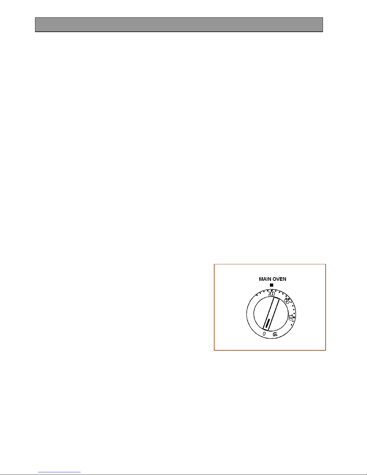
1. Turn the Main Oven Temperature control to the
required setting.
THINGS TO NOTE
· The interior oven light will come on when the
control is turned.
· The cooling fan for the controls will operate after
a time. See page 6 for further details on the
operation of the cooling fan.
· The Main Oven indicator neon will glow until the
oven has reached the desired temperature. It will
turn on and off periodically during cooking
showing that the temperature is being
maintained.
· If an automatic programme has been set, the
oven fan and oven light do not come on until the
cook time begins.
THE MAIN OVEN
Page 20
20
TO FIT THE MAIN OVEN SHELVES
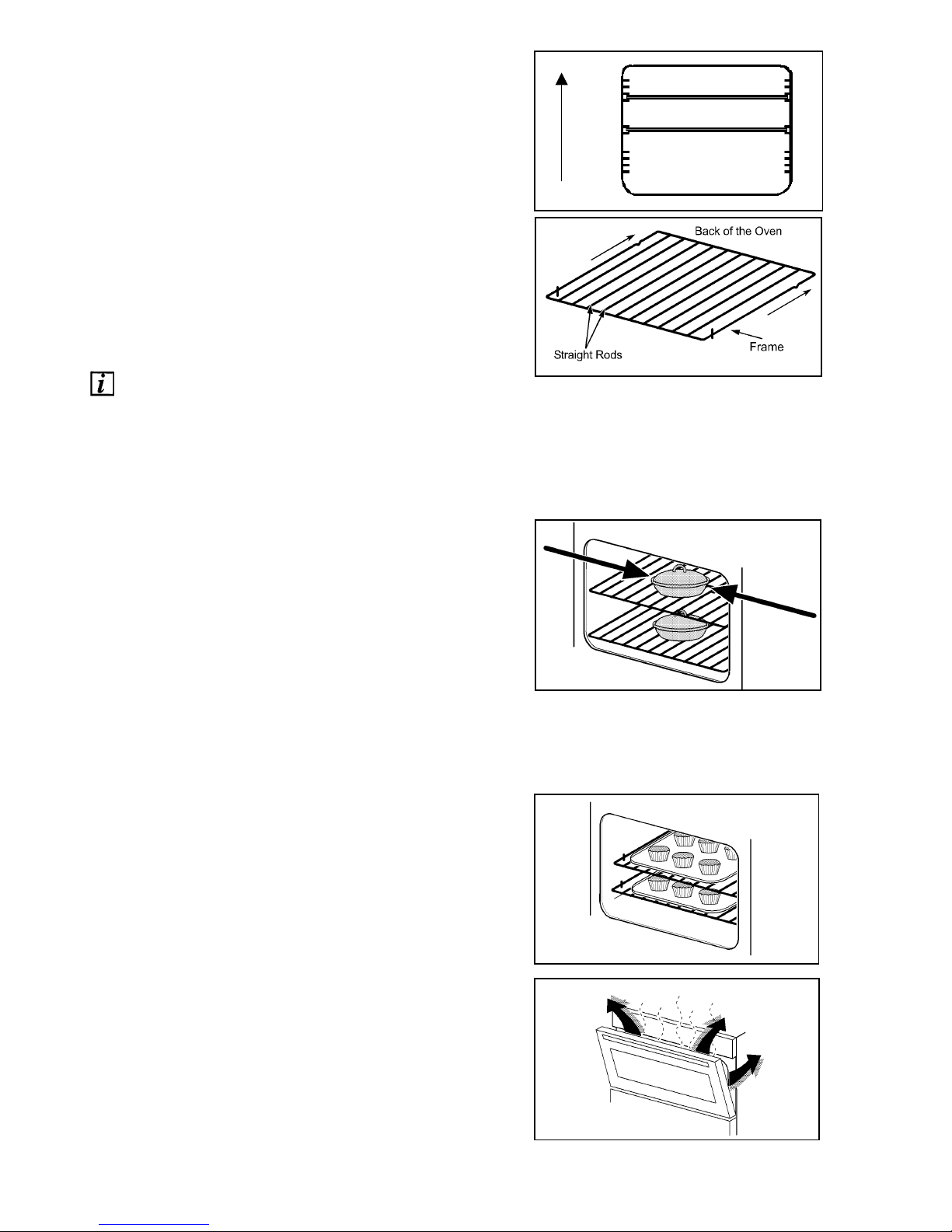
There are 7 shelf positions in the oven.
Shelves are numbered from the bottom upwards.
The shelves should be fitted with the straight rods
uppermost on the frame and the forms towards the
back of the oven. If not fitted correctly the anti-tilt
and safety stop mechanism will be affected.
HINTS AND TIPS
· Arrange the shelves in the required positions
before switching the oven on. Shelves are
numbered from the bottom upwards.
· When cooking more than one dish in the fan
oven, place dishes centrally on different shelves
rather than cluster several dishes on one shelf,
this will allow the heat to circulate freely for the
best cooking results.
· It is recommended that when baking larger
quantities, the shelf positions should be evenly
spaced to suit the load being cooked. A slight
increase in cooking time may be necessary.
· The material and finish of the baking tray and
dishes will affect the degree of base browning of
the food. Enamelware, dark, heavy or non-stick
utensils increase base browning. Shiny
aluminium or polished steel trays reflect the heat
away and give less base browning.
· The use of excessively high temperatures can
cause uneven browning. It may be necessary to
reduce temperatures slightly. Refer to the
recommendations given in the oven cooking
chart, on page 21.
· For economy leave the door for the shortest
possible time, particularly when placing food into
a pre-heated oven.
7
1
Page 21

21
The oven temperatures are intended as a guide only. It may be necessary to increase or decrease the
temperatures by a further 10°C to suit individual preferences and requirements.
Note: Shelf positions are counted from the bottom of the oven.
FOOD
SHELF
POSITION
TEMP (°C)
Biscuits
Bread
Bread Rolls/Buns
Cakes: Small & Queen
Shelf
160 - 190
210 - 220
210 - 220
160 - 170
Sponges positions 160 - 170
Victoria Sandwich 160 - 170
Madeira 140 - 150
Rich Fruit are not 140 - 150
Christmas 130 - 140
depends on size
Gingerbread critical 140 - 150
Flapjack 170 - 180
Shortbread 140 - 150
Baked Custard but ensure 140 - 150
Casseroles: Beef / Lamb 140 - 150
Chicken 160 - 180
Convenience Foods that oven According to Manufacturers
Instructions
Fish 150 - 170
Fish Pie (Potato Topped) shelves are 190 - 200
Fruit Pies, Crumbles 180 - 190
Milk Puddings 130 - 140
Pasta / Lasagne etc. evenly 180 - 190
Pastry : Choux –
Eclairs/Profiteroles 160 - 170
Flaky / Puff Pies spaced 210 - 220
Shortcrust Mince Pies 170 - 180
Meat Pies when more 210 - 220
Quiche, Tarts, Flans 180 - 190
Roasting Meat / Poultry 160 - 180
Scones than one is 200 - 210
Shepherd’s Pie 190 - 200
Soufflés 170 - 180
Vegetables: Baked Jacket Potatoes used 190 - 200
Roast Potatoes 200 - 210
Yorkshire Puddings: - Large 210 - 220
Individual 210 - 220
MAIN FAN OVEN COOKING CHART
Page 22
22
ROASTING CHART
INTERNAL TEMPERATURES –
Rare : 50-60°C; Medium : 60-70°C; Well done : 70-80°C
MEAT FAN OVEN COOKING TIME
Beef 160-180°C
20-35 minutes per ½kg (1lb)
and 20-35 minutes over
Beef, boned 160-180°C 25-35 minutes per ½kg (1lb)
and 25-35 minutes over
Mutton and Lamb 160-180°C 25-35 minutes per ½kg (1lb)
and 25-35 minutes over
Pork and Veal 160-180°C 30-40 minutes per ½kg (1lb)
and 30-40 minutes over
Ham 160-180°C 30-40 minutes per ½kg (1lb)
and 30-40 minutes over
Chicken 160-180°C 15-20 minutes per ½kg (1lb)
and 20 minutes over
Turkey and Goose 160-180°C 15-20 minutes per ½kg (1lb) up
to 3½kg (7lb) then 15 minutes
per ½kg (1lb) over 3½kg (7lb)
Duck 160-180°C 25-35 minutes per ½kg (1lb)
and 25-30 minutes over
Pheasant 160-180°C 35-40 minutes per ½kg (1lb)
and 35-40 minutes over
Rabbit 160-180°C 20 minutes per ½kg (1lb)
and 20 minutes over
Potatoes with
meat
160-180°C according to size
Potatoes without
meat
180-190°C according to size
The roasting temperatures and times given in the chart should be adequate for most joints, but slight adjustments
may be required to allow for personal requirements and the shape and texture of the meat. However, lower
temperatures and longer cooking times are recommended for less tender cuts or larger joints.
Wrap joints in foil if preferred, for extra browning uncover for the last 20 – 30 min. cooking time.
ROASTING CHART
Page 23
23
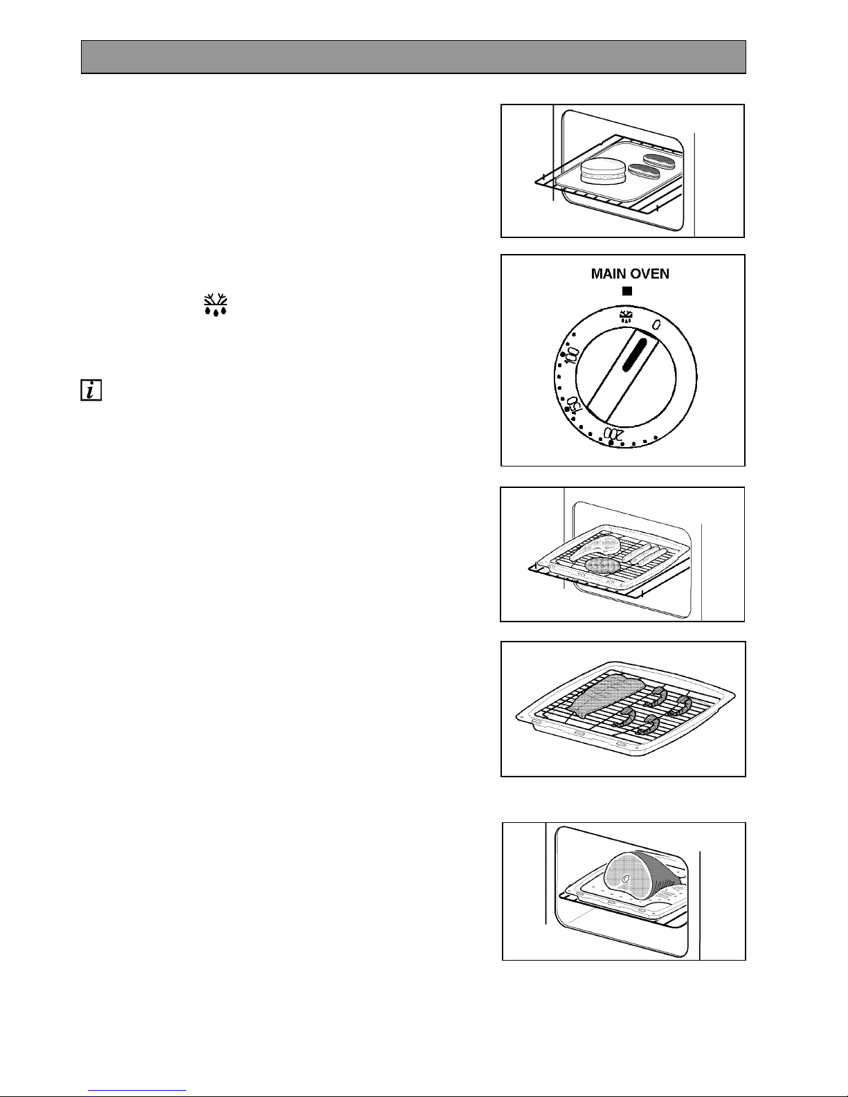
USES OF DEFROST FEATURE
This main oven function enables you to defrost most
foods without heat faster than some conventional
methods as the oven fan circulates air around the
food. It is particularly suitable for delicate frozen
foods which are to be served cold e.g. cream filled
gateaux, cakes covered with icings or frostings,
cheesecakes, biscuits, scones, etc.
HOW TO DEFROST
1. Turn the main oven temperature control to the
Defrost setting.
THINGS TO NOTE
· The oven fan and internal oven light will operate.
HINTS AND TIPS
· Place the frozen food in a single layer where
possible and turn it over half way through the
defrosting process.
· The actual speed of defrosting is influenced by
room temperature. On warm days defrosting will
be faster than on cooler days.
· It is preferable to thaw fish, meat and poultry
slowly in the fridge. However, this process can
be accelerated by using the defrost function.
Small or thin fish fillets, frozen peeled prawns,
cubed or minced meat, liver, thin chops, steaks
etc., can be thawed in 1 – 2 hours.
· A 1kg/2¼lb oven ready chicken will be thawed in
approximately 5 hours. Remove the giblets as
soon as possible during the thawing process.
· Joints of meat up to 2kg/4½lb in weight can be
thawed using the defrost function.
· All joints of meat and poultry must be thawed
thoroughly before cooking.
· Always cook thoroughly immediately after
thawing.
· DO NOT leave food at room temperature once it
is defrosted. Cook raw food immediately or store
cooked food in the fridge, once it has cooled.
· Care must always be taken when handling foods
in the home. Always follow the basic rules of
food hygiene to prevent bacterial growth and
cross contamination when defrosting, preparing,
cooking cooling and freezing foods.
DEFROST FEATURE
Page 24
24
Before cleaning the appliance always allow
the cooling fan for the controls to cool the
appliance down before switching off the
electricity supply.
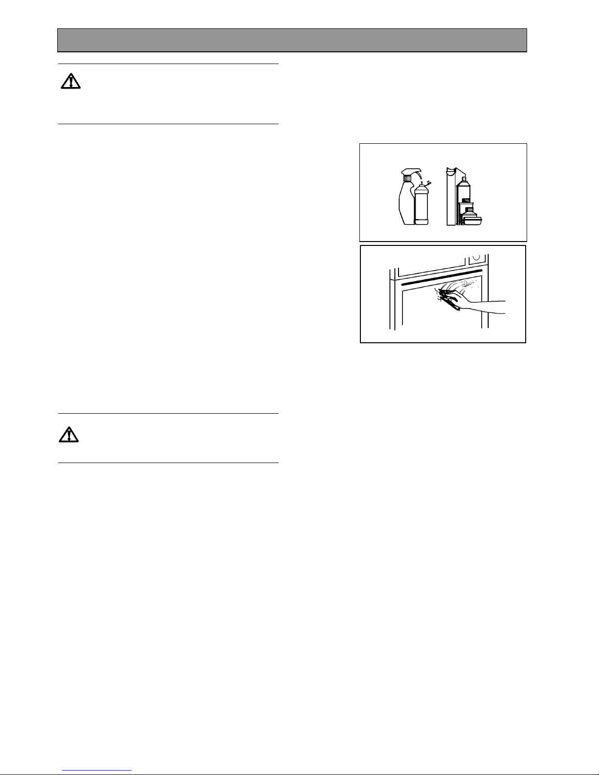
CLEANING MATERIALS
Before using any cleaning materials on your
appliance, check that they are suitable and that their
use is recommended by the manufacturer.
Cleaners that contain bleach should NOT be used as
they may dull the surface finishes. Harsh abrasives
should also be avoided.
CLEANING THE OUTSIDE OF THE
APPLIANCE
DO NOT use abrasive cleaning materials e.g. Hob
Brite, Brillo pads or scourers on painted or printed
finishes as damage may occur. Regularly wipe over
the control panel, oven doors and appliance sides
using a soft cloth and liquid detergent. To prevent
streaking on stainless steel models (where
applicable) finish with a soft cloth. Any spillage on
the stainless steel finish must be wiped off
immediately.
Stainless Steel cream cleaners are abrasive and
should be avoided as they may dull the surface
finish.
Do not attempt to remove any of the control
knobs from the appliance as this may cause
damage and is a safety hazard.
CLEANING THE CONTROL KNOBS AND
HANDLES
It is strongly recommended that only hot soapy water
is used for cleaning the control knobs and door
handles. ANY OTHER CLEANING MATERIALS
WILL DULL THE SURFACE FINISH.
CLEANING INSIDE THE OVEN AND
GRILL COMPARTMENTS
The vitreous enamel coating in the ovens and grill
compartments can be cleaned using normal oven
cleaners or aerosol oven cleaners with care. Ensure
that the manufacturers instructions are followed and
that all parts are well rinsed afterwards.
The main oven back panel is coated with a special
Stay Clean finish.
Aerosol cleaners must not be used on the
Stayclean surface and must not come into
contact with elements or the door seal as this
may cause damage.
CARE AND CLEANING
Page 25
25
CARE OF STAYCLEAN SURFACES
The Stayclean surface destroys splashes of food and
fats when the oven temperature is raised to around
220°C.
It is a good idea to run the oven for an hour or two
per week to ensure continued good performance
from the Stayclean finish.
HINTS AND TIPS
· Manual cleaning of the Stayclean surfaces IS
NOT recommended. Damage will occur if
abrasives or aerosol sprays of any kind are used.
· Slight discolouration and polishing of the
Stayclean surfaces may occur in time. This does
not affect the Stayclean properties in any way.
· A good time to allow the oven to run on is after
the weekly roast. After removing the roast, turn
the oven up to 220°C and allow to run for an hour
or so. It is important not to allow a build-up of
soilage as this can prevent the Stayclean
surfaces from working.
· Follow the recommendations below to keep oven
soilage to a minimum.
· Cook at the recommended temperatures. Higher
temperatures during roasting will increase
soilage. Try cooking at lower temperatures for
an increased length of time, you will save energy
and often the joint is more tender.
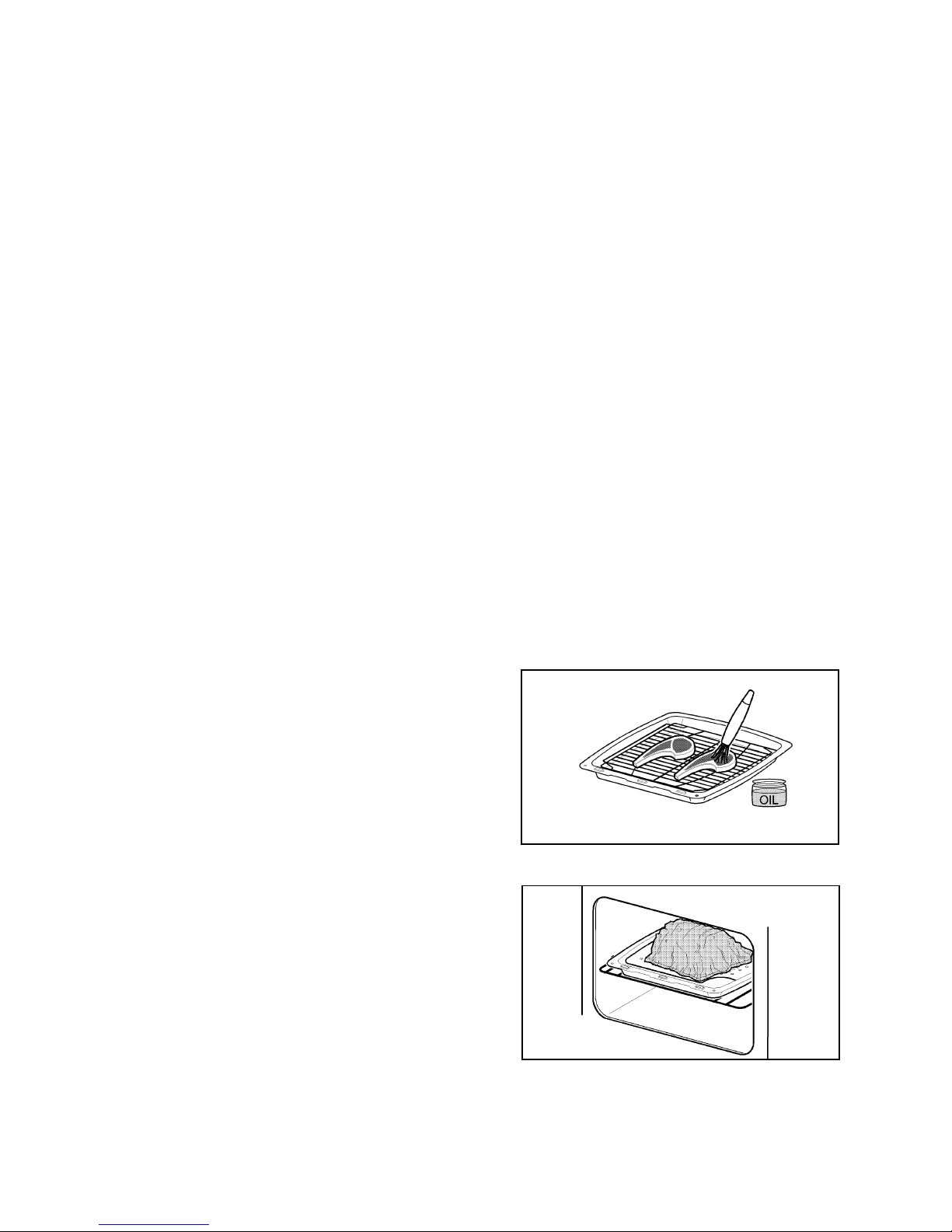
· Use minimal, if any, extra oil or fat when roasting
meat, potatoes only require brushing with fat
before cooking. Extra fat in the oven during
roasting will increase splashing and soilage.
· It is not necessary to add water to a meat tin
when roasting. The water and the fat juices from
the joint create excessive splattering during
cooking even at normal temperatures as well as
causing condensation.
· Covering joints during cooking will also prevent
splashing onto the interior surfaces. Removing
the covering for the last 20-30 minutes will allow
extra browning if required. Some large joints and
turkeys especially benefit by this method of
cooking, allowing the joint to cook through before
the outside is over-browned.
Page 26
26
CLEANING THE TOP OVEN ROOF
The grill element is hinged to make cleaning the oven
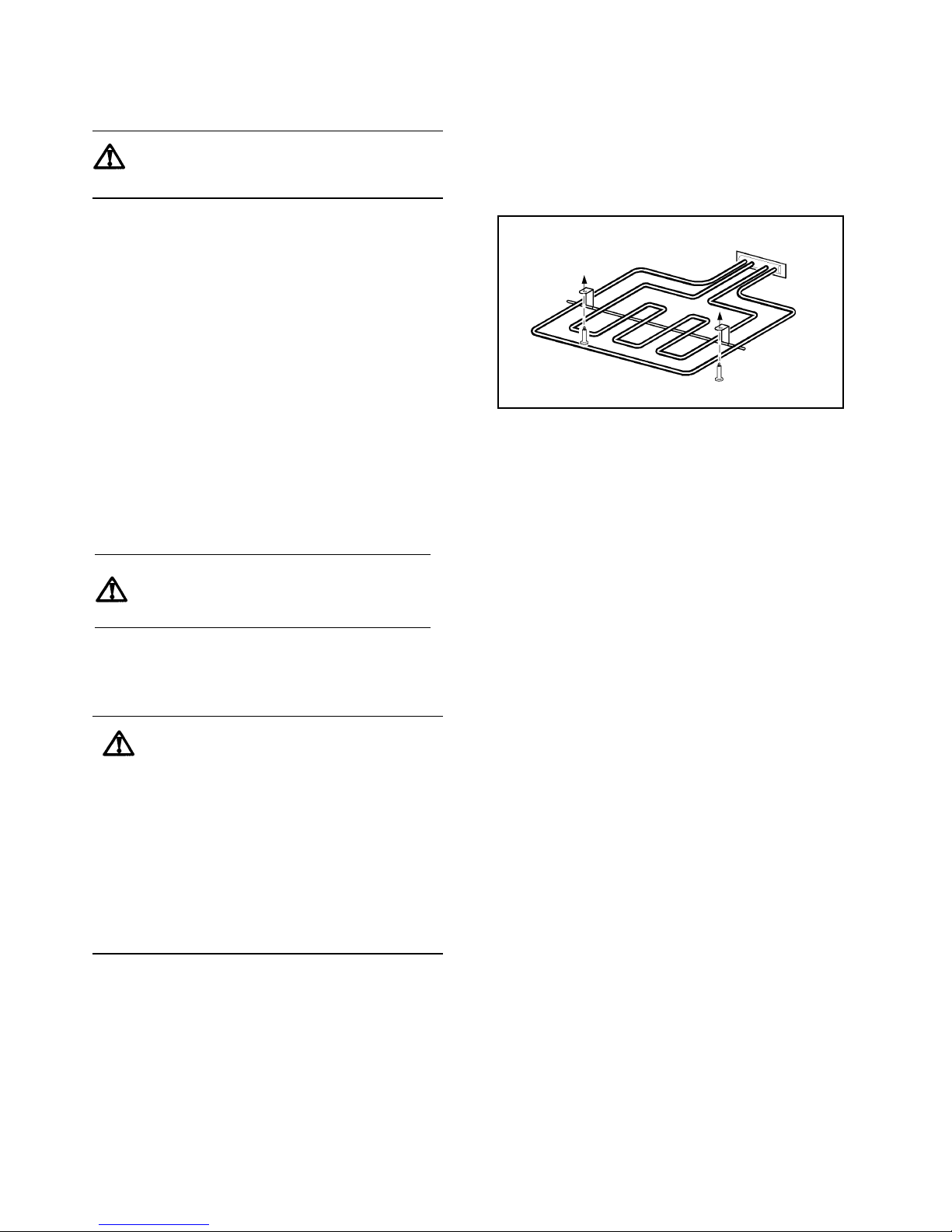
roof easier.
Switch off the appliance from the
electricity supply before cleaning and
ensure the oven is cold.
1. Remove the wirework side runners. See page 28.
2. Undo the two screws which hold the grill element
in place.
3. Gently pull the element downwards to allow
access to the oven roof. Do not force the element
downwards.
4. Clean the top of the oven with Cif cream cleaner
and a sponge scourer. If heavily soiled, aerosol
oven cleaners may be used following the
instructions given above for cleaning the grill/top
oven compartment.
5. Gently push the grill element back into place.
6. Fit the screws to hold the element in place and
tighten firmly.
7. Replace the wirework side runners.
CLEANING THE OUTER AND INNER
DOOR GLASS PANELS
To prevent damaging or weakening the
door glass panels avoid the use of the
following:
· Household detergents and bleaches
· Impregnated pads unsuitable for non-
stick saucepans
· Brillo/Ajax pads or steel wool pads
· Chemical oven pads or aerosols
· Rust removers
· Bath/Sink stain removers
The outer grill and oven door glass panels are
removable for cleaning.
Ensure the screws are firmly in place after
cleaning
Page 27
27
TO REMOVE THE OUTER GLASS
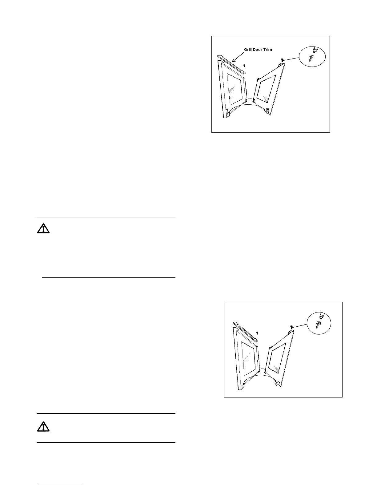
1. Open the grill or oven door slightly to gain access
to the two cross head screws on the top of the
oven door.
2. Loosen the two screws using a Pozidrive
screwdriver.
3. Hold the door glass securely in place with one
hand remove the screws and washers with the
other hand.
The screws and washers retain the trim on the top
of the grill door. Note the position of the trim on
the door.
4. Holding the door and glass with one hand, gently
pull towards you and slightly lift the door glass
with the other hand to disengage the panel from
the location point at the bottom of the door.
Gently release the door to close it.
5. Clean the outer and inner glass using hot soapy
water or Hob Brite. Should the inner face of the
outer door glass be heavily soiled it is
recommended that soapy water with a high
concentration of soap is used. To prevent
streaking, a glass cleaning spray may be applied
and the glass polished with a soft cloth. Ensure
that all parts are thoroughly dry before attempting
to replace the outer door glass.
If the door glass panel becomes chipped or
has deep scratches the glass will be
weakened and must be replaced to prevent
the possibility of the panel shattering.
Please contact your local Service Force
Centre who will be pleased to advise
further.
TO REPLACE THE OUTER DOOR GLASS
1. Holding the door glass panel with both hands,
gently place the locators into the holes of the
brackets at the bottom of the oven door.
2. Holding the door glass with your left hand, use
your right hand to open the oven door.
Bring the door gently towards the glass panel
ensuring the screw location holes line up.
3. Place the trim in the correct position on the top of
the grill door.
4. Hold the glass in place with one hand and insert
the cross head screws with washers into the
location holes with the other hand. Give the
screws one turn to ensure the glass is secure.
5. Tighten the screws positively with a Pozidrive
screwdriver before closing the oven door.
DO NOT attempt to use the oven without the
glass being in place.
Page 28
28
TO CLEAN THE INNER GLASS DOOR
The inner glass door is not removable. Clean using
hot soapy water or Hob Brite and a soft cloth. DO
NOT use abrasives as they may damage the glass or
seal.
TO REMOVE THE WIREWORK RUNNERS
The wirework runners in the grill and oven can be
removed for cleaning.
1. Remove all shelves and furniture from the grill /
oven compartments.
2. Hold the wirework at the bottom, unclip from the
cavity side and gently pull towards the centre of
the grill or oven compartment.
3. Unhook the runner at the top and remove it from
the cavity.
4. To replace, hook the wirework back into the oven
sides.
Ensure that the wirework runners are
firmly in place before refitting the
shelves.
CLEANING THE SHELVES, WIREWORK
RUNNERS AND GRILL/OVEN FURNITURE
All removable parts, except the grill pan handle, can
be washed in the dishwasher.
The grill pan, grill pan grid, meat tin oven shelves and
wirework runners may be cleaned using a soap
impregnated steel wool pad. Soaking first in hot
soapy water will make cleaning easier.
REPLACING AN OVEN LIGHT BULB
Isolate the appliance from the electricity
supply before replacing the bulb.
The type of bulb required is a 300°C, 25 watt small
Edison Screw.
1. Make sure the appliance is cool before you
replace a bulb
2. Open the oven door and remove the shelves and
wirework runners.
Instructions on how to remove the wirework
runners are given above.
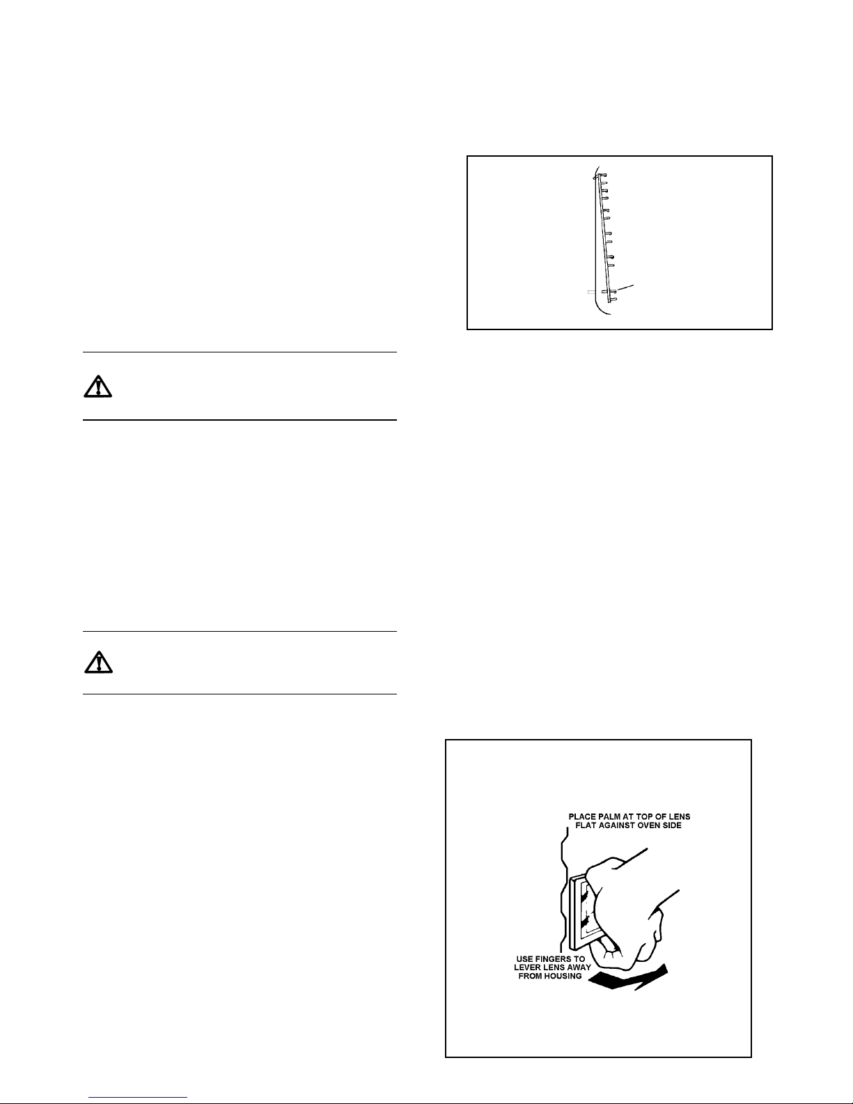
3. Pull the glass bulb cover towards you and then
pull it off. If necessary use a screwdriver to
carefully lever off the cover, taking care not to
damage the oven cavity.
4. Unscrew the bulb by turning it to the left.
5. Fit a new bulb and then replace the glass bulb
cover.
6. Refit the wirework runners and replace the oven
shelves.
7. Restore the appliance to the electricity supply and
reset the time of day.
SIDE PANEL
CAVITY CENTRE
Page 29

29
Please carry out the following checks on your appliance before calling a Service Engineer. It may be that the
problem is a simple one which you can solve yourself without the expense of a service call.
If our Service Engineer finds that the problem is listed below you will be charged for the call whether or not the
appliance is under guarantee.
PROBLEM POSSIBLE SOLUTION
The grill, oven and timer do not work.
Check that the appliance has been wired in to the
appliance supply and is switched on at the wall.
Check that the main cooker fuse is working.
The grill works but the fan oven does not.
Check that the timer is set for manual operation. See
page 9.
The grill does not work or cuts out after being used
for a long period of time.
Check that only the Grill control has been turned.
Ensure that the grill door is open when grilling.
Leave the grill door open and allow the grill to cool.
After a couple of hours check that the grill works as
normal.
Ensure the cooling fan is running when the grill is on. If
the cooling fan fails, the grill will not operate correctly.
Contact your local Service Force Centre.
The timer does not work.
Check that the instructions for the operation of the timer
are being closely followed.
The indicator neon is not working correctly.
Check that you have selected only the function you
require. Ensure all other controls are in the Off ‘0’
position.
The oven is not cooking evenly.
Check that the appliance is correctly installed and is
level.
Check that the recommended temperatures and shelf
positions are being used.
SOMETHING NOT WORKING
Page 30

30
The oven light fails to illuminate.
The oven light bulb may need replacing see page 28.
If the main oven is set for automatic cooking the light
will illuminate when the cook time begins.
The oven fan is noisy.
Check that the oven is level.
Check that the shelves and bakeware are not vibrating
in contact with the oven back panel.
The oven temperature is too high or low.
Check that the recommended temperatures and shelf
positions are being used. See page 21. Be prepared
to adjust the temperature up or down by 10°C to
achieve the results you want.
Page 31

31
SERVICE AND SPARE PARTS
In the event of your appliance requiring service, or if you wish to purchase spare parts, please contact your local
Service Force Centre by telephoning:-
0870 5 929929
Your telephone call will be automatically routed to the Service Force Centre covering your post code area.
For the address of your local Service Force Centre and further information about Service Force, please visit the
website at www.serviceforce.co.uk
Before calling out an engineer, please ensure you have read the details under the heading "Something Not
Working".
When you contact the Service Force Centre you will need to give the following details:
1. Your name, address and post code.
2. Your telephone number.
3. Clear and concise details of the fault.
4. The model and serial number of the appliance (found on the rating plate).
5. The purchase date.
Please note that a valid purchase receipt or guarantee documentation is required for in-guarantee service
calls.
CUSTOMER CARE DEPARTMENT
For general enquires concerning your Electrolux appliance, or for further information on Electrolux products, please
contact our Customer Care Department by letter or telephone at the address below or visit our website at
www.electrolux.co.uk
Customer Care Department
Electrolux
55 – 77 High Street
Slough
Berkshire
SL1 1DZ
Tel: 0870 5 950950 (*)
*calls to this number may be recorded for training purposes.
Page 32

32
Standard guarantee conditions
We, Electrolux, undertake that if within 12 months of the date of the purchase this Electrolux appliance or any
part thereof is proved to be defective by reason only of faulty workmanship or materials, we will, at our option
repair or replace the same FREE OF CHARGE for labour, materials or carriage on condition that:
· The appliance has been correctly installed and used only on the electricity supply stated on the rating
plate.
· The appliance has been used for normal domestic purposes only, and in accordance with the
manufacturer’s instructions.
· The appliance has not been serviced, maintained, repaired, taken apart or tampered with by any person
not authorised by us.
· All service work under this guarantee must be undertaken by a Service Force Centre.
· Any appliance or defective part replaced shall become the Company’s property.
· This guarantee is in addition to your statutory and other legal rights.
Home visits are made between 8.30am and 5.30pm Monday to Friday. Visits may be available outside these
hours in which case a premium will be charged.
Exclusions
This guarantee does not cover:
· Damage or calls resulting from transportation, improper use or neglect, the replacement of any light bulbs
or removable parts of glass or plastic.
· Costs incurred for calls to put right an appliance which is improperly installed or calls to appliances
outside the United Kingdom.
· Appliances found to be in use within a commercial environment, plus those which are subject to rental
agreements.
· Products of Electrolux manufacture which are not marketed by Electrolux.
European Guarantee
If you should move to another country within Europe then your guarantee moves with you to your new home
subject to the following qualifications:
· The guarantee starts from the date you first purchased your product.
· The guarantee is for the same period and to the same extent for labour and parts as exists in the new
country of use for this brand or range of products.
· This guarantee relates to you and cannot be transferred to another user.
· Your new home is within the European Community (EC) or European Free Trade Area.
· The product is installed and used in accordance with our instructions and is only used domestically, i.e. a
normal household.
· The product is installed taking into account regulations in your new country.
Before you move please contact your nearest Customer Care centre, listed below, to give them details of your
new home. They will then ensure that the local Service Organisation is aware of your move and able to look
after you and your appliances.
France Senlis +33 (0) 3 44 62 20 13
Germany Nürnberg +49 (0) 800 234 7378
Italy Pordernone +39 (0) 800117511
Sweden Stockholm +46 (0) 20 78 77 50
UK Slough +44 (0) 1753 219898
GUARANTEE CONDITIONS
Page 33

33
Voltage: 230-240 Volts AC 50Hz
Loading Info:
Dual Grill: 2.8kW
Main Fan Oven
Fan Element: 2.5kW
Fan Motor: 0.03kW
Oven Light: 0.05kW
Wattage: 4.9 - 5.3kW
Height: 720 mm
Width: 593 mm
Depth: 585 mm
(excluding handles and knobs)
Weight: 50.kg
This appliance complies with: European Council Directive 73/23/EEC.
EMC Directive 89/336/EEC.
CE Marking Directive 93/68/EEC.
TECHNICAL DETAILS
Page 34
NOTES
34
WARNINGS:
· This appliance must be installed by a
qualified electrician/competent person.
Safety may be impaired if installation is
not carried out in accordance with these
instructions.
· This appliance must be earthed.
· Do not remove the screws from the
earth tab extending from the oven
mains terminal block (Fig. 1).
· Before connecting the appliance make
sure that the voltage of your electricity
supply is the same as that indicated on
the rating plate. This is situated on the
lower front frame of the appliance and
can be seen upon opening the door.
Alternatively the rating plate may also
be found on the back or top of some
models (where applicable).
· Do not alter the electrical circuitry of
this appliance.
CHOICE OF ELECTRICAL CONNECTION
· The appliance should be operated using at least
6mm
2
twin core and earth PVC insulated
multicore cable. Please choose from the most
appropriate after reading the descriptions:
· By connecting the appliance to a cooker point
having a double pole isolating switch providing at
least 3mm contact separation in all poles and
protected with a fuse or miniature circuit breaker
at your mains fuse box.
· If you wish to connect an oven and a hob to a
cooker point you can, by connecting the oven
and hob separately to the cooker point. Oven
and hob units should be separately connected to
a cooker point. See Fig. 2.
Fig. 2
INSTALLATION INSTRUCTIONS
Fig.1
Page 35
35
NOTE: It is good practice to :
· Fit an Earth Leakage Circuit Breaker to your
house wiring.
· Wire your appliance to the latest IEE regulations.
THINGS TO NOTE
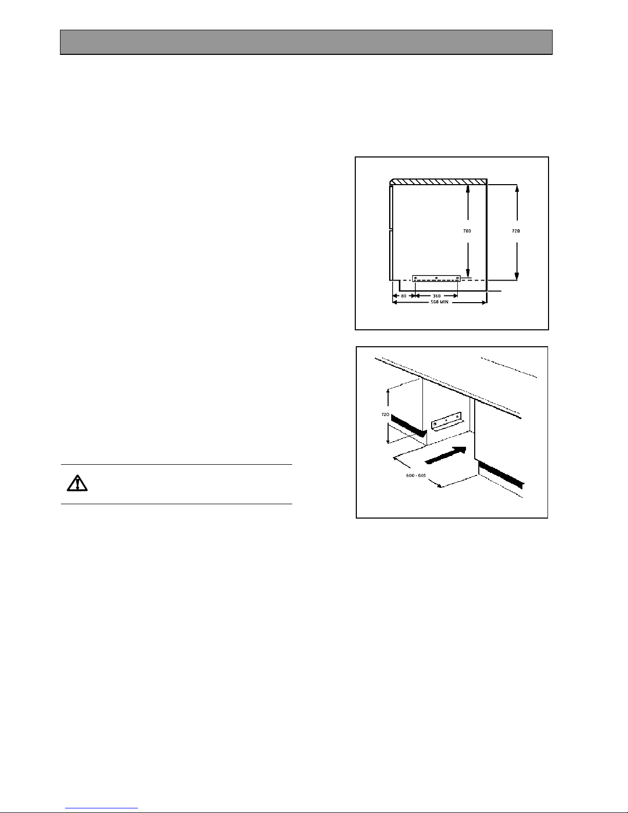
· This appliance is designed to be fitted between
cabinets with the recommended dimensions as
shown Fig. 3 & 4.
· If there is an existing housing unit it must be
removed.
· The dimensions given provide adequate air
circulation around the unit within the cabinet,
ensuring compliance with BS EN60-335.
· This appliance must not be installed on the
wooden base board.
· Enquiries regarding the installation of the cooker
point, if required, should be made to your
Regional Electricity Company to ensure
compliance with their regulations.
· The cooker point should be within 2m of the
appliance to make it accessible to switch off the
appliance in case of an emergency.
· To protect the hands, wear gloves when lifting
the oven into its housing.
Do not lift the appliance by the handles.
NOTE: HOUSE CIRCUIT
Earth leakage and continuity tests must be carried
out before the appliance is connected to the mains
supply and re-checked after fitting.
INSTALLATION INSTRUCTIONS
Fig. 3
Fig. 4
Page 36
NOTES
36
PREPARING CABINET FOR FITTING OF
OVEN
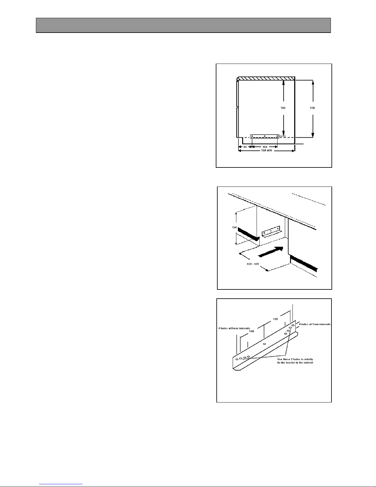
· Make sure the space between the cabinets is the
correct size for the appliance to be fitted (Ref.
Fig. 5 & 6).
· The plinth board spanning the space into which
the appliance is to be installed should be
removed.
· If the size is between adjacent cabinets is 605-
610mm, then the cabinets should be modified so
that the recommended dimension of at least 600605mm is maintained.
· The adjacent cabinets must be stable and level
by firmly securing it to the wall or floor. If
necessary, make arrangements to ensure the
shelf upon which the oven will rest is level.
· The adjacent cabinets must be stable and firmly
secured to the wall or floor. If necessary, make
arrangements to ensure the work surface below
which the oven will rest is level.
· Drill two pilot screw holes into the sides of the
adjacent cabinets, in the positions indicated by
Fig. 5.
· Fit the appliance mounting brackets using the
two holes indicated in Fig. 7 to the adjacent
cabinets ( Ref. Fig. 5 & 6).
INSTALLATION INSTRUCTIONS
Fig. 5
Fig. 6
Fig. 7
Page 37
37
· Check that the mounting brackets are level.
They can be adjusted if necessary by using the
extra holes at the ends of the brackets. Once the
brackets are level, drill a pilot hole through the
central hole in the bracket and fit the remaining
screw.
HOW TO FINISH UNPACKING
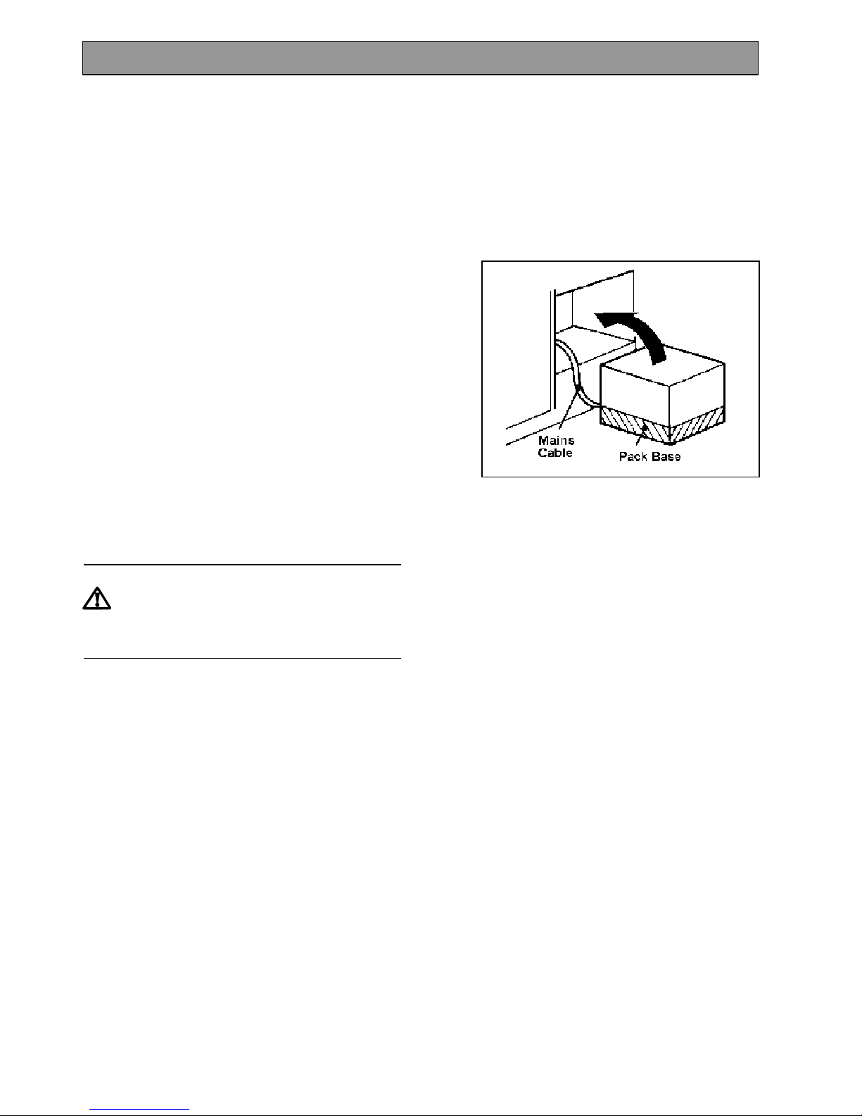
· Place packed appliance next to the space in
which it will be installed. See Fig. 8.
· Remove the appliance packing except for bottom
tray which should be left in position until the
appliance is ready to be fitted into its cabinet.
· Ensure the owner is given these operating
instructions.
NOTE: It is imperative that the appliance is
left in the base to protect both the appliance
and the floor.
Important: Switch off at mains, miniature
circuit breaker and, if appropriate, remove
fuse before commencing any electrical
work.
INSTALLATION INSTRUCTIONS
Fig.8
Page 38
NOTES
38
TO REMOVE COVER OF MAINS
TERMINAL
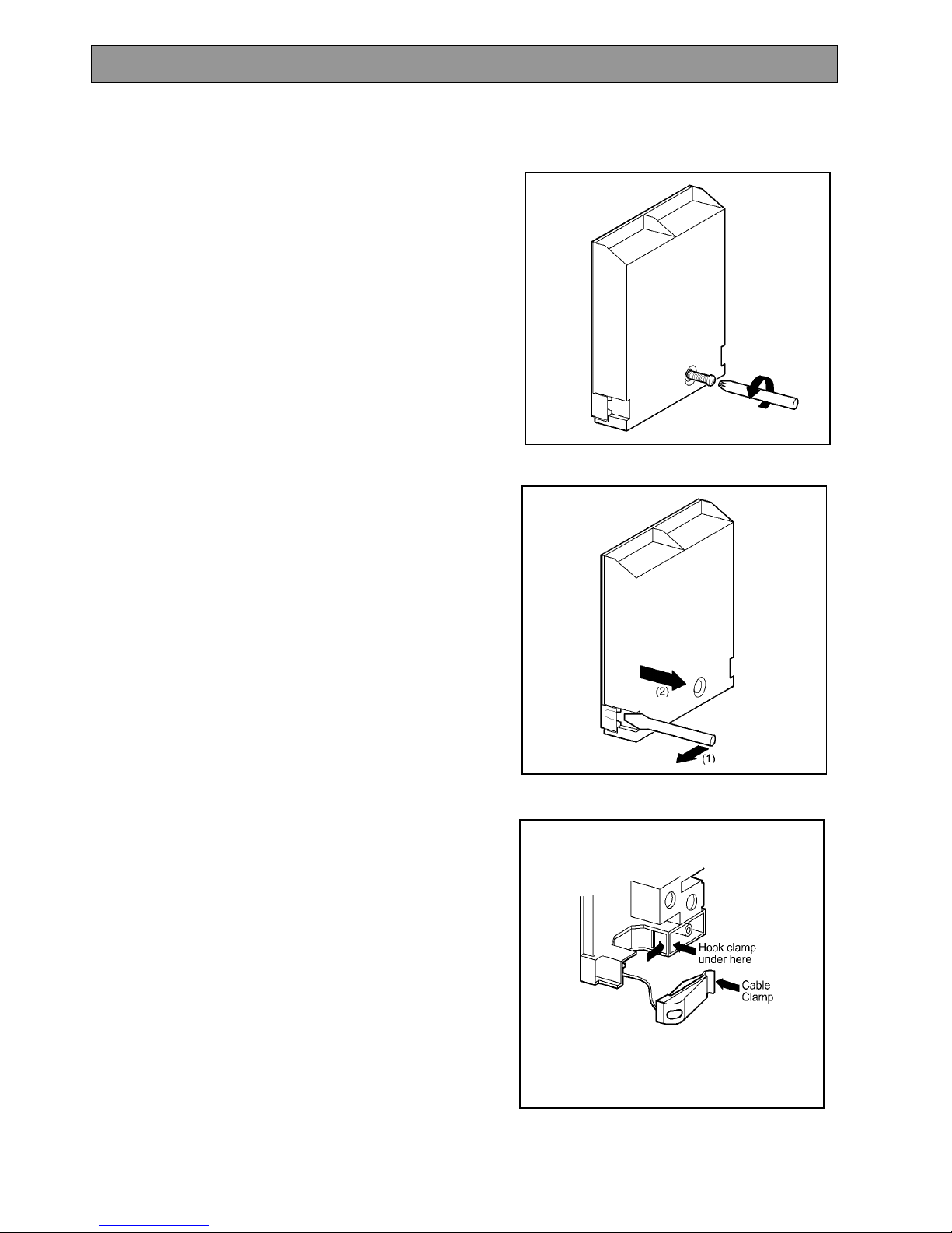
From the rear of the appliance, remove mains input
terminal cover to gain access to terminal block.
· First remove retaining screw with pozidrive
screwdriver. See Fig. 9.
· Prise cover loose using screwdriver in position
(1) then lever off with screwdriver in position (2)
at either side. See Fig. 10.
· Lift cover and remove screw from cable clamp.
See Fig. 11.
Fig. 9
Fig.10
Fig.11
MAKING THE ELECTRICAL CONNECTIONS
Page 39
39
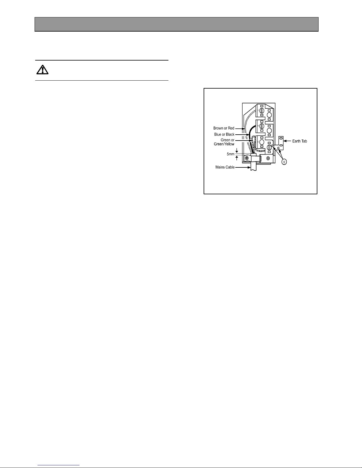
CONNECTING TO THE MAINS TERMINAL
Warning: This appliance must be earthed.
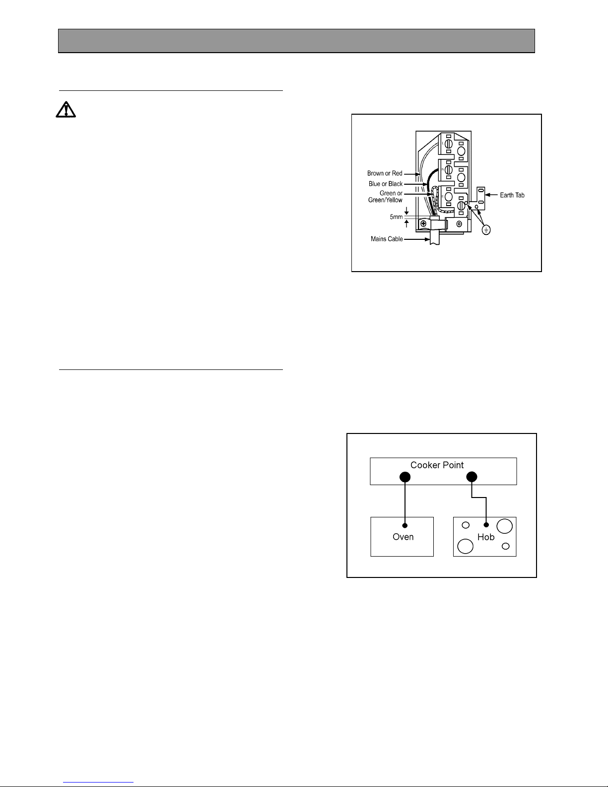
· We recommend you use a new length of 6mm
2
twin core and earthed cable to ensure your
safety.
· Make connection as shown in Fig. 12 by
proceeding as follows:-
· Preform wires to the appropriate shape to suit
fitting into the mains terminal block.
· Strip inner insulation on wires using
wirestrippers.
· Twist the bared wires using pliers.
· Cut bared wires 10mm away from the end of the
inner insulation. Where uninsulated Earth wires
are used ensure they are suitably sheathed to
leave 10mm bare wire to fit into the terminal.
· Clamp bare wires into the relevant terminal and
check they are held by tugging each one in turn.
· Clamp the mains cable securely ensuring 5mm of
the outer insulation is inside the terminal block
and that the wires are not taught but not so slack
as to cause any fouling. See Fig. 12.
· Connect the remaining end to the mains cable to
the cooker point/junction box.
· Place fuse/miniature circuit breaker in circuit and
switch on at mains.
MAKING THE ELECTRICAL CONNECTIONS
Fig.12
Page 40
NOTES
40
CHECKING ELECTRICAL CONNECTIONS
· Confirm the appliance is correctly connected by
switching on and observing the various oven
functions indicators.
CONNECTING TO A HOB OR COOKER
POINT
· Either follow in general terms the instructions for
connecting to the terminal block or refer to the
hob suppliers installation instructions.
Feed the cable through the cabinet and
arrange to route the cable away from the
appliance.
NOTE: HOUSE CIRCUIT
Earth leakage and continuity tests must be carried
out before the appliance is connected to the mains
supply and re-checked after fitting.
MAKING THE ELECTRICAL CONNECTIONS
Page 41
41
FITTING INTO THE SPACE BETWEEN
CABINETS
IMPORTANT: Ensure that the oven is
switched off at the wall before any further
work is carried out.
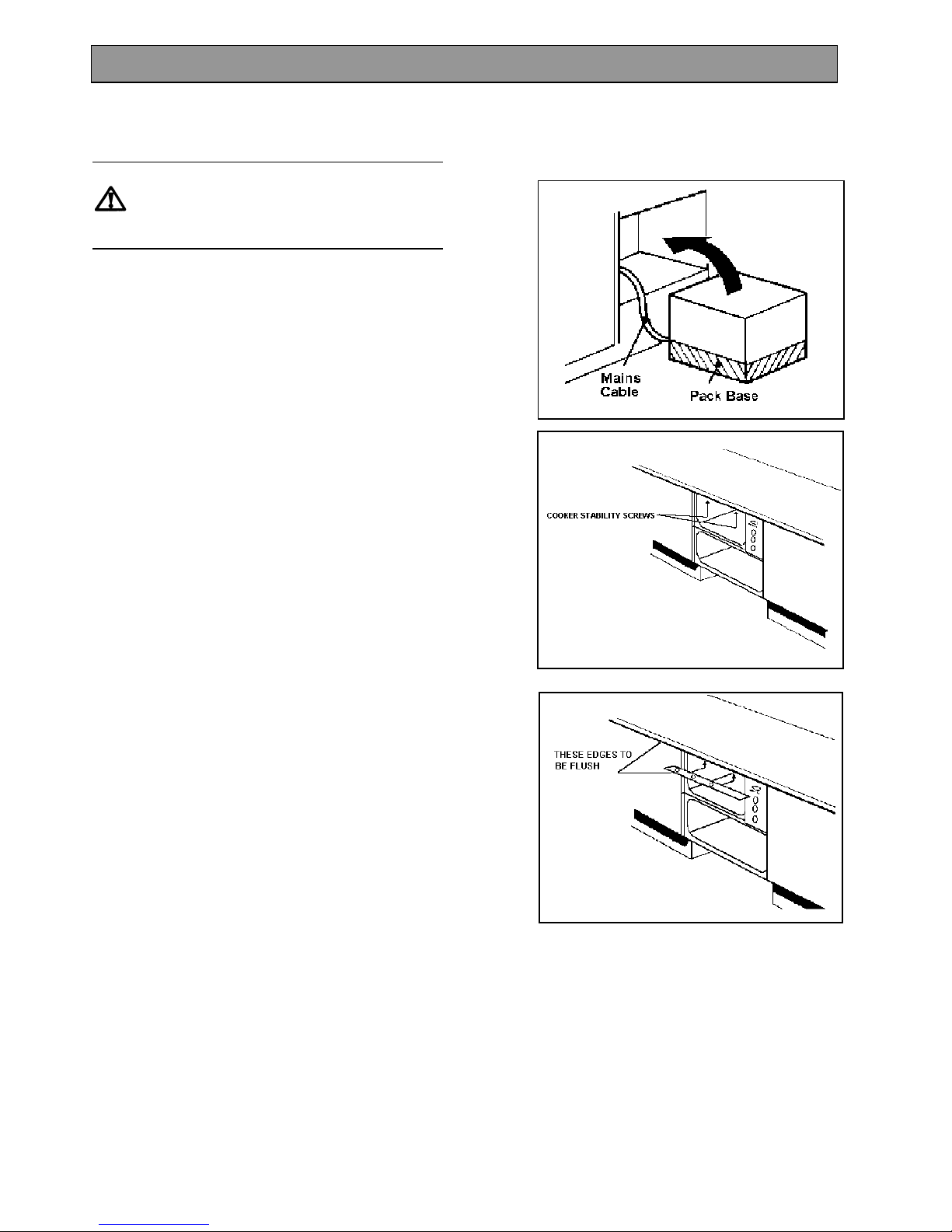
· Ensure the appliance is in front of the cabinet.
See Fig. 13.
· Take out all oven furniture before installation to
reduce the weight you need to lift.
· To place the appliance into the space between
cabinetry follow the procedure below:
· N.B. Two people will be required to carry out
the lifting procedure.
· Warning: Do not attempt to lift this appliance by
the handle(s).
Each person should squat either side of the
appliance.
Tilt the appliance so that your hands can support
the underside of the appliance.
Raise the appliance to the correct height.
Rest the rear underside of the appliance on the
mounting brackets while your hands support the
front.
The appliance can be pushed fully into the
space. Take care to avoid fouling the mains lead.
Ensure the appliance is central and level.
· When the appliance is fully housed, screw the
stability screws (supplied with the appliance) into
the underside of the worksurface in the positions
indicated (see Fig. 14), taking care not to distort
the trim. It is advisable to turn each screw
alternatively to avoid damaging the trim.
· Place the top trim flush with the edge of the
worksurface, with the cork spacers up over (see
Fig.15) and screw into position using the screws
supplied with the appliance.
· Replace the plinth board.
· Switch on the appliance and refer the user to the
operating instructions.
INSTALLATION INSTRUCTIONS
Fig.14
Fig.15
Fig.13
Page 42

NOTES
42
Page 43

NOTES
43
Page 44

IMPORTANT NOTICE
In line with our continuing policy of research and development, we reserve the right to alter models and
specifications without prior notice.
This instruction booklet is accurate at the date of printing, but will be superseded if specifications or appearance are
changed.
ELECTROLUX
55 – 77 HIGH STREET,
SLOUGH,
BERKSHIRE,
SL1 1DZ.
TELEPHONE 0870 5 950950
www.electrolux.co.uk
Part Number: 311653600
© Electrolux plc 2003
 Loading...