

Page 1
Use & Care Manual EN 2
Laundry Center
Manuel d’utilisation et d’entretien FR 79
Centre de buanderie
Manual de uso y cuidado SP 157
Centro de lavado
electrolux.com
Page 2
2
IMPORTANT SAFETY INFORMATION
Please Read and Save this
Manual
Thank you for choosing Electrolux, our
premium brand in home appliances. This
& Care Manual
customer satisfaction and product quality
throughout the service life of your new
appliance.
We view your purchase as the beginning
of a relationship. To ensure our ability to
continue serving you, please use this page
to record important product information.
is part of our commitment to
Use
Keep a Record for Quick
Reference
Purchase date
Electrolux serial number
Electrolux model number
Electrolux model series*
* The series number can be found within the
Model number (example ELTE7600AW=7600
series).
NOTE
Table of Contents
Important Safety Information ........................... 2
Features .....................................................................9
Pre-Installation Requirements ........................ 10
Installation ...............................................................21
Washer Controls and Settings...................... 40
Dryer Controls and Settings ........................... 48
Washer Operating Instructions ..................... 54
Dryer Operating Instructions ......................... 58
Normal Operating Sounds ............................. 60
Stain Removal Guide ..........................................61
Care and Cleaning ............................................ 63
Troubleshooting .................................................. 68
Limited Warranty ..................................................77
Questions?
For toll free telephone support or on-line
support in the US and Canada contact:
U.S.
1-877-4ELECTROLUX (1-877-435-3287)
www.electrolux.com
Canada
1-800-265-8352
www.electrolux.ca
Registering your product with Electrolux
enhances our ability to serve you. You can
register on-line at
www.electrolux.com, by sending your
Product Registration Card in the mail, or
PHOTOREGISTERSM using a smart phone.
See registration card for details.
READ ALL INSTRUCTIONS BEFORE
OPERATING THIS LAUNDRY
CENTER.
SAVE THESE INSTRUCTIONS FOR
FUTURE REFERENCE.
Page 3
IMPORTANT SAFETY INFORMATION
IMPORTANT SAFETY INSTRUCTIONS - GAS DRYER
3
WARNING
FIRE or explosion hazard
Failure to follow safety warnings exactly could
result in serious injury, death, or property damage.
DO NOT store or use gasoline or other flammable
vapors and liquids in the vicinity of this or any other
appliance.
WHAT TO DO IF YOU SMELL GAS:
DO NOT try to light any appliance.
DO NOT touch any electrical switch; DO NOT use
any phone in your building.
• Clear the room, building or area of all
occupants.
• Immediately call your gas supplier from a
neighbor’s phone. Follow the gas supplier’s
instructions.
• If you cannot reach your gas supplier, call the
fire department.
Installation and service must be performed by
a qualified installer, service agency or the gas
supplier.
DANGER
If using Liquid Propane (LP), STOP and install the LP
kit before operating your gas dryer.
Page 4
4
IMPORTANT SAFETY INFORMATION
WARNING
RISK OF FIRE
• Ensure the entire laundry center exhaust system is clean and free of lint and debris
prior to the installation of your new laundry center. The entire exhaust system
should be inspected and cleaned a minimum of every 18 months with normal
usage. Failure to comply with cleaning your exhaust system will increase the RISK
of FIRE.
• DO NOT install the laundry center with flexible plastic or flexible foil venting material.
Flexible venting materials are known to collapse, be easily crushed and trap lint.
These conditions will obstruct laundry center airflow and increase the risk of fire.
• DO NOT screen the exhaust ends of the vent system, or use any screws, rivets or
other fasteners that extend into the duct to assemble the exhaust system. NO screen
or grate of any mesh size is allowed to cover the outdoor exhaust opening.
• Install the laundry center according to the manufacturer’s instructions and local codes.
• Laundry center installation and service must be performed by a qualified installer,
service agency or the gas supplier.
• The electrical service to the laundry center must conform with local codes and
ordinances and the latest edition of the National Electrical Code, ANSI/NFPA 70, or
in Canada, the Canadian Electrical Code CSA C22.1 part 1.
• The gas service to the laundry center must conform with local codes and ordinances
and the latest edition of the National Fuel Gas Code ANSI Z223.1/NFPA 54, or in
Canada, the Natural Gas and Propane Installation Code, CSA B149.1. An individual
manual shutoff valve must be installed within 6 ft. (1.83 m) of the laundry center in
accordance with the National Fuel Gas Code, ANSI Z223.1/NFPA 54.
• The laundry center is designed under ANSI Z21.5.1/CSA 7.1 or UL 2158 - CAN/
CSA C22.2 No. 112 (latest editions) for HOME USE only. This laundry center is not
recommended for commercial applications such as restaurants, beauty salons, etc.
• Destroy the carton and plastic bags after the laundry center is unpacked. Children
might use them to play. Cartons covered with rugs, bedspreads, or plastic sheets
can become airtight chambers causing suffocation. Place all materials in a garbage
container or make materials inaccessible to children.
• To reduce the risk of severe injury or death, follow all installation instructions in this
manual.
WARNING
For your safety, the information in this manual must be followed to minimize the risk of fire
or explosion or to prevent property damage, personal injury or loss of life. DO NOT store
or use gasoline or other flammable vapors and liquids in the vicinity of this or any other
appliance. This
situation that may occur. Common sense and caution must be practiced when installing,
operating and maintaining any appliance.
Use & Care Manual
is not meant to cover every possible condition and
WARNING
Any damage resulting from improper disassembly/assembly or installation of product is
not covered by product warranty.
Page 5
IMPORTANT SAFETY INFORMATION
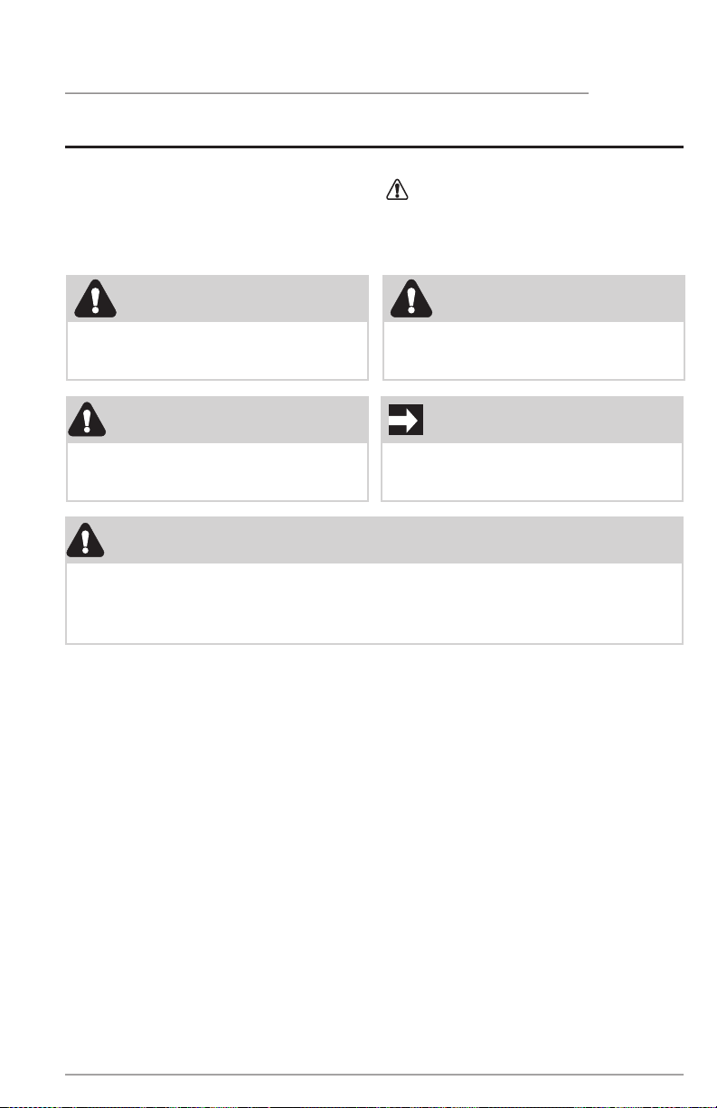
Important Safety Instructions
5
Safety Precautions
DO NOT attempt to install or operate your
unit until you have read the safety precautions
in this manual. Safety items throughout this
manual are labeled with a Danger, Warning,
or Caution based on the risk type.
DANGER
DANGER indicates an imminently
hazardous situation which, if not avoided,
will result in death or serious injury.
WARNING
WARNING indicates a potentially
hazardous situation which, if not avoided,
could result in death or serious injury.
Definitions
This is the safety alert symbol. It is used
to alert you to potential personal injury
hazards. Obey all safety messages that
follow this symbol to avoid possible injury
or death.
CAUTION
CAUTION indicates a potentially
hazardous situation which, if not avoided,
may result in minor or moderate injury.
IMPORTANT
IMPORTANT indicates installation,
operation or maintenance information
which is important but not hazard-related.
WARNING
FIRE HAZARD
To reduce the risk of fire, electrical shock, or injury to persons when using this laundry
center, comply with the warnings listed below. Failure to comply with these Important Safety
Information and warnings could result in property damage, serious personal injury, or death.
Prevent Fire
READ ALL INSTRUCTIONS BEFORE
USING THE APPLIANCE.
DO NOT wash or dry items that have
been previously cleaned in, soaked
in, or spotted with gasoline, cleaning
solvents, kerosene, waxes, or other
flammable or explosive substances. DO
NOT store these items on or near the
laundry center. These substances give
off vapors that could ignite or explode.
DO NOT place items exposed to
cooking oils in your dryer. Items
contaminated with cooking oils may
contribute to a chemical reaction
that could cause a load to catch
fire. To reduce the risk of fire due to
contaminated loads, the final part of a
tumble dryer cycle occurs without heat
(cool down period). Avoid stopping
a tumble dryer before the end of the
drying cycle unless all items are quickly
removed and spread out so that the
heat is dissipated.
DO NOT dry articles containing rubber,
plastic or similar materials such as
bras, galoshes, bath mats, rugs, bibs,
baby pants, plastic bags and pillows
that may melt or burn. Some rubber
materials, when heated, can under
certain circumstances produce fire by
spontaneous combustion.
DO NOT operate the dryer if the lint
screen is blocked, damaged or missing.
Fire hazard, overheating and damage to
fabrics can occur.
DO NOT obstruct the flow of ventilating
air. DO NOT stack or place laundry or
throw rugs against the front or back of
the laundry center.
DO NOT spray any type of aerosol into,
on or near laundry center at any time.
DO NOT use fabric softeners or products
to eliminate static unless recommended
by the manufacturer of the fabric
softener or product.
Page 6
6
IMPORTANT SAFETY INFORMATION
WARNING
Clean the lint screen before or after each
load. The interior of the dryer, lint screen
housing and exhaust duct should be
cleaned approximately every 18 months
by qualified service professional. An
excessive amount of lint build-up in these
areas could result in inefficient drying and
possible fire. See Care and Cleaning.
FIRE HAZARD
WARNING
The dryer operation of a laundry center
produces combustible lint. The dryer must
be connected to an outdoor exhaust.
Regularly inspect the outdoor exhaust
opening and remove any accumulation of
dust, dirt, and lint around the opening and
in the surrounding area.
FIRE HAZARD
WARNING
DO NOT continue to use the laundry center
if you hear squeaking, grinding, rubbing
or other unusual noises. This could be a
sign of mechanical breakdown and lead
to fire or serious injury. Contact a qualified
technician immediately.
• Do not wash items that have been
previously cleaned in, soaked in,
or spotted with gasoline, cleaning
solvents, kerosene, cooking oils,
waxes, or other flammable or explosive
substances. Do not store these items on
or near the washer. These substances
give off vapors or chemical reactions
that could ignite or explode.
DO NOT put oily or greasy rags or
clothing on top of the washer. These
substances give off vapors that could
ignite the materials.
DO NOT add gasoline, cleaning
solvents, or other flammable or
explosive substances to the wash water.
These substances give off vapors that
could ignite or explode.
DO NOT store or use gasoline or other
flammable vapors or liquids in the
vicinity of this or any other appliance.
• Under certain conditions, hydrogen gas
may be produced in a hot water system
that has not been used for 2 weeks or
more. HYDROGEN GAS IS EXPLOSIVE.
If the hot water system has not been
used for such a period, before using the
washer, turn on all hot water faucets
and let the water flow from each for
several minutes. This will release any
accumulated hydrogen gas. Hydrogen
gas is flammable; DO NOT smoke or use
an open flame during this time.
Failure to comply with these warnings could
result in fire, explosion, serious bodily injury
and/or damage to the laundry center
Protect Children
• Risk of suffocation and injury from
entrapment. Do not allow children to
play on or in the laundry center. Close
supervision of children is necessary
when the laundry center is used. As
children grow, teach them the proper,
safe use of all appliances.
• Destroy the carton, plastic bag and
other packing materials after the
laundry center is unpacked. Children
might use them for play. Cartons
covered with rugs, bedspreads or
plastic sheets can become airtight
compartments.
• Keep laundry products out of children’s
reach. To prevent personal injury,
observe all warnings on product labels.
• Remove the laundry center doors to
prevent accidental entrapment before
the laundry center is removed from
service or discarded.
• Failure to comply with these warnings
could result in serious personal injuries.
Risk of Child Entrapment
Child entrapment and suffocation are not
problems of the past. Junked or abandoned
laundry centers are still dangerous – even if
they will sit for “just a few days”. If you are getting
rid of your old laundry center, please follow the
instructions below to help prevent accidents.
Page 7

IMPORTANT SAFETY INFORMATION
7
We strongly encourage responsible appliance
recycling/disposal methods. Contact your
State/Provence Energy Office, Local Electric
and Water Utilities or Conservation Program
Office or visit www.energystar.gov/recycle
for more information on recycling your old
laundry center.
Before You Throw away Your Old
Laundry Center
• Remove doors
• Remove the electric power cord
• Secure all hoses and drain pipes to
prevent water from leaking out and
creating a slip hazard.
Prevent Injury
• To prevent shock hazard and assure
stability during operation, the laundry
center must be installed and electrically
grounded by a qualified service person
in accordance with local codes.
Installation instructions are included
in this manual for reference. Refer to
the installation sections for detailed
grounding procedures. If the laundry
center is moved to a new location, have
it checked and reinstalled by a qualified
service professional.
• To prevent personal injury or damage to
the laundry center, the electrical power
cord of a gas dryer must be plugged
into a properly grounded and polarized
3-prong outlet. The third grounding prong
must never be removed. Never ground
the dryer to a gas pipe. DO NOT use an
extension cord or an adapter plug.
• To prevent personal injury or damage
to the washer, the electrical power cord
of the washer must be plugged into
a properly grounded and polarized
3-prong outlet. The third grounding
prong must never be removed. Never
ground the washer to a gas pipe.
DO NOT use an extension cord or an
adapter plug.
DO NOT use any type of spray cleanser
when cleaning laundry center interior.
Hazardous fumes or electrical shock
could occur.
• To prevent injury, DO NOT reach into
the washer or dryer if the drum is
moving. Wait until the dryer has stopped
completely before reaching into the
drum.
• Do not operate either the washer or
dryer if they are separated from one
another.
Prevent Injury and Damage to the
Laundry Center
To prevent serious personal injury and
damage to the laundry center:
• All repairs and servicing must
be performed by an authorized
service provider unless specifically
recommended in this use and care
manual. Use only authorized factory
parts. Do not separate the dryer from
the washer if you are not a qualified
service professional.
DO NOT tamper with controls.
DO NOT sit on, step on or stand on
the laundry center. DO NOT rest heavy
loads on top. The laundry center is not
meant to support weight.
DO NOT install or store the laundry
center where it will be exposed to
standing water, dripping water or
outdoor weather conditions.
• Thermal limiter switches automatically
turn off the motor in the unlikely event
of an overheated situation. A service
technician must replace the thermal
limiter switch(es) after correcting the fault.
DO NOT install on carpet. Install
laundry center on a solid floor. It may
be necessary to reinforce the floor to
prevent vibration or movement.
• To reduce the risk of electric shock,
disconnect this appliance from the
power supply before attempting
any user maintenance. Pressing the
power button does not disconnect this
appliance from the power supply.
• This laundry center is equipped with
an electrical overload protector
which will stop the motor if it becomes
overheated.
• Do not use replacement parts that
have not been recommended by the
manufacture (e.g. parts made at home
using a 3D printer).
• Failure to comply with these warnings
could result in serious personal injuries.
Page 8
8
IMPORTANT SAFETY INFORMATION
CAUTION
Do not, under any circumstances, cut,
remove, or bypass the grounding prong.
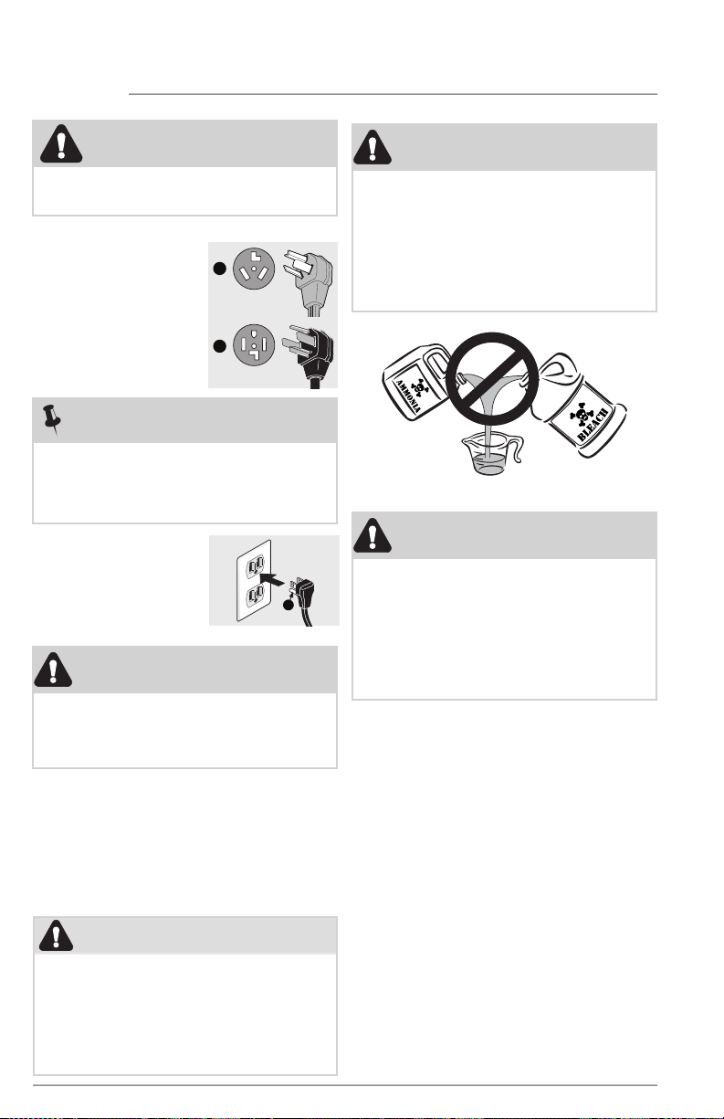
208/240V Electric Dryer
1. 10-30R 3-wire (fused
30 amp)
2. 14-30R 4-wire (fused
30 amp)
1
2
NOTE
UL - approved service cord must be
installed on electric dryers (not provided
with unit except those manufactured for
sale in Canada).
120V Gas Dryer
1. Power cord with
grounded prong.
1
WARNING
Improper grounding of the washer may cause
serious injury or death. Check with a licensed
electrician if you are in doubt as to whether
the appliance is properly grounded.
WARNING
HARMFUL VAPOR HAZARD
DO NOT use or mix liquid chlorine bleach
with other household chemicals such
as toilet cleaners, rust removers, acids
such as vinegar, or products containing
ammonia. These mixtures can produce
dangerous fumes which can cause serious
injury or death.
WARNING
RISK OF INJURY
DO NOT WASH: Water resistant and water
repellent clothing or other materials.
Failure to follow these instructions may
result in an abnormal vibrating and outof-balance condition that could result in
physical injury, property damage, and/or
appliance damage.
• Follow package directions when using
laundry products. Incorrect usage can
produce poisonous gas - resulting in
serious injury or death.
DO NOT combine laundry products
for use in 1 load unless specified on
the label.
WARNING
ELECTRICAL SHOCK HAZARD
This equipment has two connections to
the power supply. Disconnect both power
supply connections before servicing.
Each appliance shall be connected to an
individual branch circuit only. The washer
and dryer must be on separate circuits.
Page 9
FEATURES
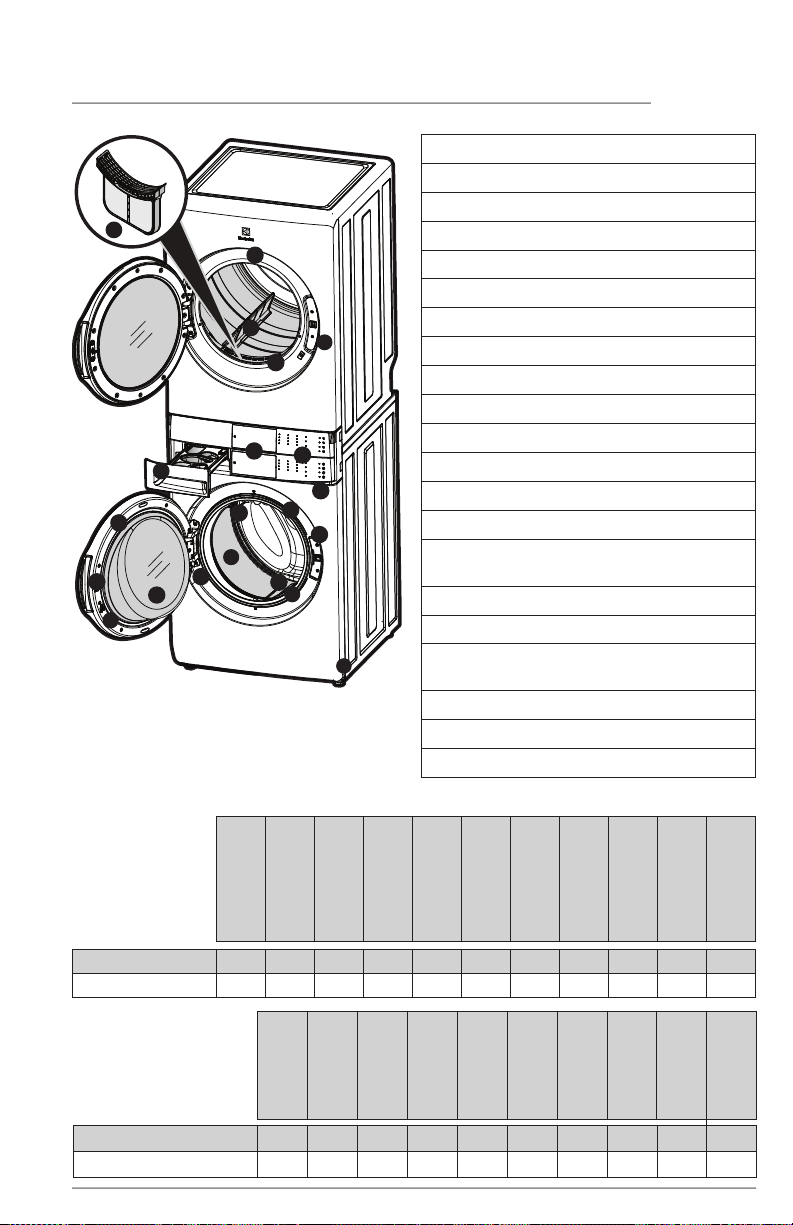
1. Door striker
2. Reversible door
3. Laundry products dispenser
21
19
20
4
3
2
1
15
16
Not all cycles, options, or features listed
are available on every model.
Refer to the tables below for an overview of features available for each model series.
6
12
14
17
18
5
7
8
10
9
13
11
Washer
4. LED Display
5. Cycle Display
6. Drum light (select models)
7. Control lock
8. Serial and model #
9. Cascading wash vanes
10. Door latch with safety lock
11. Adjustable leveling legs
12. Stainless steel wash drum
13. Flexible door gasket
14. Wide angle door hinge
15. Inner bowl with small article
redistribution ramp
16. Door stand ventilation
17. Door Latch
18. Front-Mounted Moisture Sensor (on
select models)
19. Drum Light (on select models)
20. 3 Drum Vanes
21. LuxCare™ Lint Shield
9
7300 Series
7600 Series
Dryer
7300 Series
7600 Series
drum light
door reversibility
Adaptive
Dispenser™
detergent pack
option
pure rinse
optic whites
allergen
sanitize
stain treatment
perfect steam
no yes yes no no no no no yes no 15
yes yes yes yes yes yes yes yes yes yes 15
Door
Reversibility
Perfect
Steam
Wrinkle
Release
Extended
Tumble
Drum Light
Delay Time
Control Lock
Sanitize
Eco Dry
yes no yes yes no yes yes no yes 15 min
yes yes yes yes yes yes yes yes yes 15 min
fast wash
min
min
Fast Dry
Page 10
10
PREINSTALLATION REQUIREMENTS
Installation Checklist
Shipping Hardware
Foam shipping support (under wash
tub) removed and stored
Shipping bolts and spacers removed
from rear of appliance and stored
Hole plugs (shipped in manual bag)
installed in holes in backsheet
Leveling
Washer is level, side-to-side and front-
to-back
Cabinet is sitting solid on all corners
Water Supply
Use only new hoses and verify rubber
sealing washers are installed
HOT supply is connected to HOT inlet
and COLD supply is connected to
COLD inlet
HOT and COLD water supply
turned on
No leaks present at water supply
connections or appliance inlet
connections - recheck in 24 hours
Drain
Stand pipe or wall drain height
minimum 24”
Verify anti-siphon disc is attached
toward end of drain hose
Drain hose secured in place with
cable tie (shipped in drum)
Exhaust Venting
Free-flowing, clear of lint buildup
4 inch (102 mm) rigid metal or
semi-rigid metal transition ducting
of minimal length and turns
NO foil or plastic venting material
Approved vent hood exhausted to
outdoors
Door Reversal
Follow detailed instructions in
this manual
Test hinge and latch for function
Gas Supply (Gas Dryer)
Manual shutoff valve present in supply
All connections sealed with approved
sealer and wrench tight
Conversion kit for LP GAS system
# PCK4200 (not included) and must be
purchased separately
Gas supply turned on
No leaks present at all connections -
check with soapy water, NEVER check
with flame
240v Electric Supply
(Electric Dryer)
Approved NEMA 10-30 or 14-30 service
cord with all screws tight on terminal
block
Approved strain relief installed
Terminal access cover installed before
initial operation
Water Hookup (Select Models)
Inspect hoses for proper placement of
rubber washers
Water supply is turned on
Check for leaks
Steam model dryers require use of
ASSEMBLY HOSE Kit #5304495002
(not included) and must be purchased
separately.
Electrical Power
House power turned on
Washer plugged in
Dryer plugged in
Final Checks
Installation instructions and Use
& Care Manual read thoroughly
Door locks and water enters drum
when cycle starts
Washer door latches and drum tumbles
when cycle starts
Dryer door latches and drum tumbles
when cycle starts
Registration card sent in
Page 11
PREINSTALLATION REQUIREMENTS
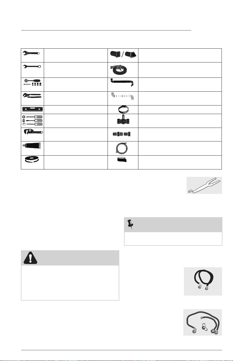
Tools and Materials Needed for Installation:
1. Adjustable Wrench OR 7. Flat or Louvered External Vent
3/8” or 10 mm box
wrench OR
Ratchet and Socket set 9. 4 in. rigid metal exhaust duct
2. Adjustable Pliers 4 in. semi-rigid metal exhaust
3. Carpenter’s Level 10. 4 in. (10.2 cm) clamp
4. Phillips, Flat, & Square
Bit Screwdrivers
5. Pipe Wrench for gas
supply
6. LP Resistant Sealant OR 13. Flexible gas supply line (Gas
LP Resistant Thread
Tape
11
Hood
8. 3 or 4 wire 240 volt cord kit
(Electric Laundry center) OR
work OR
duct work
11. Gas Line Shutoff Valve (Gas
Laundry center)
12. 1/2” NPT union flare adapters (x2)
laundry center)
14. Metal foil tape (not duct tape)
Replacement Parts in U.S. and
Canada:
If replacements parts are needed for
your washer, you can contact the source
where you purchased your washer, call
1-877-4ELECTROLUX (1-877-435-3287) in
the U.S. or 1-800-265-8352 in Canada, or
visit our website, www.electrolux.com in the
U.S. or www.electrolux.ca in Canada for
the Electrolux Authorized Parts Distributor
nearest you.
Accessories
CAUTION
Do not attempt to use a pedestal with this
laundry center. Failure to use accessories
manufactured by (or approved by) the
manufacturer could result in personal
injury, property damage or damage to the
laundry center.
LP CONVERSION KIT
P/N PCK4200
Gas laundry centers intended for use in
a location supplied with LP must use a
conversion kit prior to installation.
UNIVERSAL APPLIANCE WRENCH
P/N 137019200
A Universal Appliance
Wrench is available to aid
in laundry center/washer/
pedestal feet adjustment.
TOUCH UP PAINT PENS*
Classic White Touch Up Pen -
P/N 5304468812
NOTE
Hoses are not included with washer
purchase.
ASSEMBLY HOSE KIT
P/N 5304495002
For use in laundry center models that
include a steam feature.
INLET HOSE KITS
Please call 866-233-
8353 (in Canada, 800265-8352) to explore
hose kit options that will
meet your specific installation needs.
DRAIN HOSE EXTENSION
KIT P/N 137098000
In order to reach
standpipe heights or
distances beyond the
reach of the drain hose supplied, order the
Drain Hose Extension Kit
Inlet hose x2
Page 12
12
PREINSTALLATION REQUIREMENTS
Electrical System
Requirements
NOTE
Because of potentially inconsistent voltage
capabilities, the use of this laundry center
with power created by gas powered
generators, solar powered generators,
wind powered generators or any other
generator other than the local utility
company is not recommended.
Electrical Requirements for
Electric Dryer:
CIRCUIT - Individual 30 amp. branch circuit
fused with 30 amp. time delay fuses or
circuit breakers. Use separately fused
circuits for washer and dryer. DO NOT
operate washer and dryer on same circuit.
POWER SUPPLY - 3-wire or 4-wire, 120/240
volt, single phase, 60 Hz, Alternating
Current.
WARNING
FIRE HAZARD
• Failure to follow safety warnings exactly
could result in serious injury, death, or
property damage.
• DO NOT install a booster fan in dryer
exhaust duct.
• Install all laundry centers in accordance
with the installation instructions in this
manual.
NOTE
A 120/208 volt, single phase, 60 Hz,
Alternating Current supply may be used on
dryers marked for use on rating plate.
IMPORTANT
The laundry center is internally grounded
to neutral unless it was manufactured for
sale in Canada.
Only a 4-conductor cord shall be used
when the appliance is installed in a
location where grounding through the
neutral conductor is prohibited. Grounding
through the neutral link is prohibited for: (1)
new branch circuit installations, (2) mobile
homes, (3) recreational vehicles, and (4)
areas where local codes DO NOT permit
grounding through the neutral.
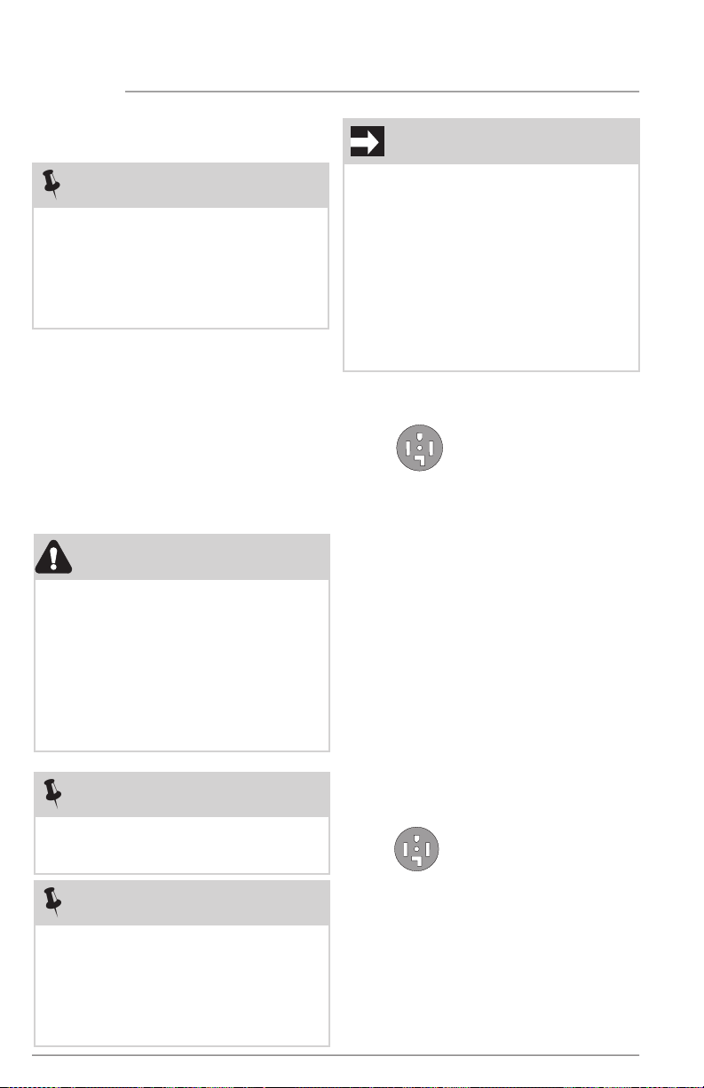
3-wire Power Supply Cord (not
supplied)
3-wire receptacle
(NEMA type 10-30R)
The dryer MUST employ a 3-conductor
power supply cord NEMA 10-30 type SRDT
rated at 240 volt AC minimum,
30 amp, with 3 open end spade lug
connectors with upturned ends or closed
loop connectors and marked for use with
clothes dryers. For 3-wire cord connection
instructions see “Electrical connection
(non-Canada) - 3-wire cord” in Electrical
Installation section.
OUTLET RECEPTACLE - NEMA 10-30R
receptacle to be located so the power
supply cord is accessible when the
laundry center is in the installed position.
GROUNDING CONNECTION - See
“Grounding requirements” in Electrical
Installation section.
4-wire Power Supply Cord
(not supplied)
4-wire receptacle
(NEMA type 14-30R)
NOTE
The electric laundry center has been
designed and certified to operate at both
240V and 208V. Drying times on a 208V
power supply will, however, be approximately
20% longer than drying times on a 240V
power supply. This is normal and expected
behavior and applies to all drying cycles.
The dryer MUST employ a 4-conductor
power supply cord NEMA 14-30 type SRDT
or DRT (as required) rated at 240 volt AC
minimum, 30 amp, with 4 open end spade
lug connectors with upturned ends or closed
loop connectors and marked for use with
clothes dryers. For 4-wire cord connection
instructions see “Electrical connection
(non-Canada) - 4-wire cord” in Electrical
Installation section.
Page 13
PREINSTALLATION REQUIREMENTS
13
NOTE
Laundry centers manufactured for sale
in Canada have factory-installed, 4-wire
power supply cord (NEMA 14-30).
OUTLET RECEPTACLE - NEMA 14-30R
receptacle to be located so the
power supply cord is accessible when
the laundry center is in the installed
position.
GROUNDING CONNECTION - See
“Grounding requirements” in Electrical
Installation section.
Electrical Requirements for
Gas Dryer:
CIRCUIT - Individual, properly polarized
and grounded 15 amp. branch circuit
fused with 15 amp. time delay fuse or
circuit breaker.
POWER SUPPLY - 2-wire, with ground, 120
volt, single phase, 60 Hz, Alternating
Current.
POWER SUPPLY CORD - Dryer is equipped
with 120 volt 3-wire power cord.
GROUNDING CONNECTION - See
“Grounding requirements” in Electrical
Installation section.
WARNING
Improper grounding of the laundry center
may cause serious injury or death. Check
with a licensed electrician if you are in
doubt as to whether the appliance is
properly grounded.
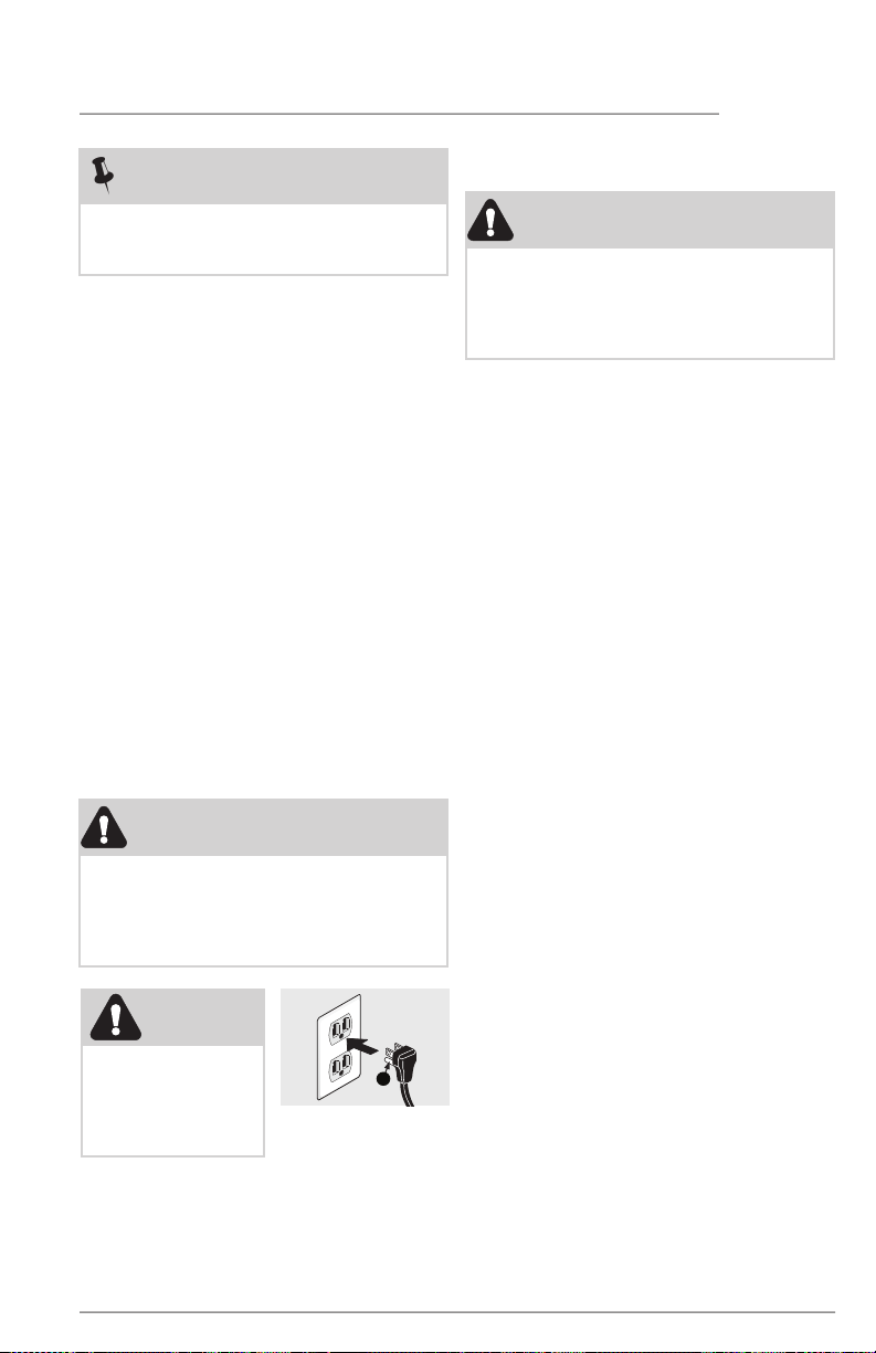
CAUTION
Do not, under any
circumstances, cut,
remove, or bypass
the grounding
prong.
1. Power cord with
grounded prong.
1
Gas Supply Requirements
WARNING
EXPLOSION HAZARD
Uncoated copper tubing will corrode when
subjected to natural gas, causing gas leaks.
Use ONLY black iron, stainless steel, or
plastic-coated brass piping for gas supply.
1. The gas service to the laundry center
must conform with local codes and
ordinances and the latest edition of the
National Fuel Gas Code ANSI Z223.1/
NFPA 54, or in Canada, the Natural
Gas and Propane Installation Code,
CSA B149.1.
2. The gas supply line should be 1/2 inch
(1.27 cm) pipe.
3. If codes allow, flexible metal tubing
may be used to connect your laundry
center to the gas supply line. The
tubing MUST be constructed of
stainless steel or plastic-coated brass.
4. The gas supply line MUST have an
individual shutoff valve installed in
accordance with the B149.1, Natural
Gas and Propane Installation Code.
5. A 1/8 inch (0.32 cm) N.P.T. plugged
tapping, accessible for test gauge
connection, MUST be installed
immediately upstream of the gas
supply connection to the laundry
center.
6. The laundry center MUST be
disconnected from the gas supply
piping system during any pressure
testing of the gas supply piping system
at test pressures in excess of 1/2 psig
(3.45 kPa).
7. The laundry center MUST be isolated
from the gas supply piping system
during any pressure testing of the gas
supply piping system at test pressures
equal to or less than 1/2 psig (3.45
kPa).
8. Connections for the gas supply
must comply with the Standard for
Connectors for Gas Appliances, ANSI
Z21.24/CSA 6.10.
Page 14
14
PREINSTALLATION REQUIREMENTS
Electrical System
Requirements for Washer
CIRCUIT - Individual, properly polarized
and grounded 15 amp. branch circuit
fused with 15 amp. time delay fuse or
circuit breaker.
POWER SUPPLY - 2 wire, with ground, 120
volt single phase, 60 Hz, Alternating
Current.
OUTLET RECEPTACLE - Properly grounded
3-prong receptacle to be located so
the power supply cord is accessible
when the washer is in an installed
position.
WARNING
ELECTRIC SHOCK HAZARD
Certain internal parts are intentionally
not grounded and may present a risk
of electrical shock if contacted during
installation. Do not contact the following
parts while the appliance is energized
• Pump
• Drive motor
• Electrical control boards
• Water valves
WARNING
ELECTRICAL SHOCK HAZARD
Improper connection of the equipment
grounding conductor can result in a risk
of electrical shock. Check with a licensed
electrician if you are in doubt as to whether
the appliance is properly grounded.
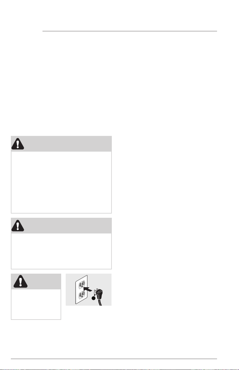
CAUTION
Do not, under any
circumstances, cut,
remove, or bypass
the grounding
prong.
1. Power cord with
grounded prong.
1
Grounding requirements
1. The washer MUST be grounded. In the
event of malfunction or breakdown,
grounding will reduce the risk of
electrical shock by a path of least
resistance for electrical current.
2. Since your washer is equipped with
a power supply cord having an
equipment-grounding conductor and
a grounding plug, the plug MUST be
plugged into an appropriate, copper
wired receptacle that is properly
installed and grounded in accordance
with all local codes and ordinances or
in the absence of local codes, with the
National Electrical Code, ANSI/NFPA
70 (latest edition), or in Canada, the
Canadian electrical code C22.1 part 1.
If in doubt, call a licensed electrician.
DO NOT cut off or alter the grounding
prong on the power supply cord. In
situations where a two-slot receptacle
is present, it is the owner’s responsibility
to have a licensed electrician replace it
with a properly grounded three prong
grounding type receptacle.
Water Supply Requirements
Hot and cold water faucets MUST be
installed within hose length of your washer’s
water inlet. The faucets MUST be 3/4 inch
(1.9 cm) with threading for laundry hose
connection. Water pressure MUST be
between 20 and 120 psi. Pressure difference
between hot and cold cannot be more than
10 psi. Your water department can advise you
of your water pressure.
Drain System Requirements
1. Drain capable of eliminating 17 gals
(64.3 L) per minute.
2. A standpipe diameter of 1-1/4 in. (3.18
cm) minimum.
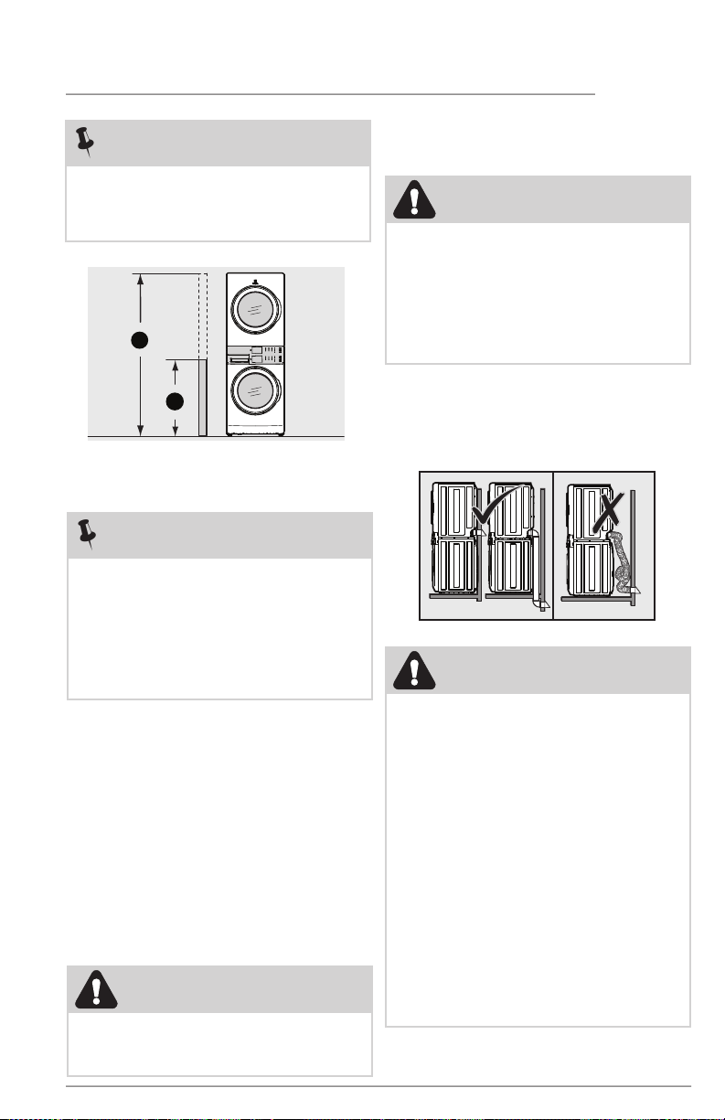
3. The standpipe height above the floor :
Minimum height: 24 in. (61 cm)
Maximum height: 96 in. (244 cm).
Page 15
PREINSTALLATION REQUIREMENTS
15
NOTE
Drain hose length is 59 in. (150 cm). For
installations requiring a longer drain hose,
use hose P/N 137098000, available from
an authorized parts distributor.
1
2
1. 96” (244cm) max.
2. 24” (61 cm) min.
NOTE
For installations requiring a longer
drain hose, have a qualified technician
install a longer drain hose (according to
your model number) available from an
authorized parts distributor. For drain
systems in the floor, install a siphon break
kit available from your local hardware
store.
Exhaust System Requirements
Duct Work Requirements
Use only 4 inch (102 mm) diameter rigid
or flexible metal duct and approved vent
hood which has a swing-out damper(s) that
open when the dryer is in operation. When
the dryer stops, the dampers automatically
close to prevent drafts and the entrance of
insects and rodents. To avoid restricting the
outlet, maintain a minimum of 12 inches (30.5
cm) clearance between the vent hood and
the ground or any other obstruction.
WARNING
FIRE HAZARD
Failure to follow these instructions can create
excessive drying times and fire hazards.
The following are specific requirements for
proper and safe operation of your laundry
center.
WARNING
FIRE HAZARD
DO NOT install a laundry center with
flexible plastic or metal foil venting
materials. Flexible venting materials are
known to collapse, be easily crushed and
trap lint. These conditions will obstruct
laundry center airflow and increase the
risk of fire.
If your present system is made up of plastic
duct or metal foil duct, replace it with a
rigid or semi-rigid metal duct. Also, ensure
the present duct is free of any lint prior to
installing dryer duct.
WARNING
FIRE HAZARD
• A laundry canter must be exhausted
outdoors.
• DO NOT exhaust laundry center into
a chimney, a wall, a ceiling, an attic, a
crawl space or any concealed space of
a building.
• A laundry center produces combustible
lint. If the laundry center is not
exhausted outdoors, some fine lint
will be expelled into the laundry area.
An accumulation of lint in any area of
the home can create a health and fire
hazard.
• Regularly inspect the outdoor exhaust
opening and remove any accumulation
of lint around the outdoor exhaust
opening and in the surrounding area.
Page 16
16
PREINSTALLATION REQUIREMENTS
The laundry center must be connected to
an exhaust outdoors. Prior to installing
your new laundry center, inspect the
outdoor exhaust opening and remove any
accumulation of lint around the outdoor
exhaust opening and in the surrounding
area.
WARNING
FIRE HAZARD
• DO NOT allow combustible materials
(for example: clothing, draperies/
curtains, paper) to come in contact
with exhaust system. The laundry
center MUST NOT be exhausted into
a chimney, a wall, a ceiling, or any
concealed space of a building which
can accumulate lint, resulting in a fire
hazard.
DO NOT screen the exhaust ends of the
vent system, or use any screws, rivets or
other fasteners that extend into the duct
to assemble the exhaust system. No
screen, grate, or guard of any mesh
size is allowed to cover
the exhaust opening.
Lint can become caught
in the screen, grate,
guard, or on the screws or
rivets, clogging the duct work
and creating a fire hazard as well
as increasing drying times. Use an
approved vent hood to terminate the
duct outdoors, and seal all joints with
metal foil tape. All male duct pipe
fittings MUST be installed downstream
with the flow of air.
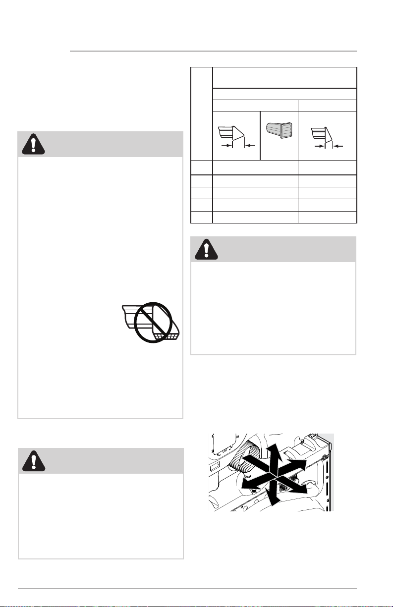
Max. Number of 90°
turns
4” (10.2 cm) louvered 2.5” (6.35 cm)
0 125 ft. (38 m) 110 ft. (33.5 m)
1 115 ft. (35 m) 100 ft. (30.5 m)
2 105 ft. (32 m) 90 ft. (27.5 m)
3 95 ft. (29 m) 80 ft. (24.5 m)
4 85 ft. (26 m) 70 ft. (21.5 m)
MAXIMUM LENGTH
of 4” (102 mm) Rigid Metal Duct
VENT HOOD TYPE
(Preferred)
WARNING
FIRE HAZARD
• DO NOT install flexible plastic or flexible
foil venting material.
• DO NOT exceed 8 ft. (2.4 m) duct length
if installing semi-rigid venting.
• DO NOT use screws, rivets or other
fasteners that extend into the duct to
assemble the exhaust system.
Exhaust Direction
Directional exhausting can be accomplished
by installing a quick-turn 90° dryer vent elbow
directly to exhaust outlet of dryer. Dryer vent
elbows are available through your local parts
distributor or hardware store.
WARNING
FIRE HAZARD
Never exceed more than 4-90˚ elbows in
the exhaust duct system. Exceeding the
length of duct pipe or number of elbows
allowed in the “MAXIMUM LENGTH”
charts can cause an accumulation of lint
in the exhaust system. Plugging the system
could create a fire hazard, as well as
increase drying times.
See Clearance Requirements
Page 17
PREINSTALLATION REQUIREMENTS
NOTE
90° quick-turn elbows
are required to meet
minimum installation
depth.
WARNING
FIRE HAZARD
DO NOT install the laundry center where
gasoline or other flammables are kept or
stored. Installation must be a minimum of
18 inches (45.7 cm) above the floor if the
laundry center is in a garage. Failure to
do so can result in death, explosion, fire
or burns.
In installations where the exhaust system is
not described in the charts, the following
method must be used to determine if the
exhaust system is acceptable:
1. Connect an inclined or digital
manometer between the laundry center
and the point the exhaust connects to
the laundry center.
2. Set the dryer timer and temperature to
air fluff (cool down) and start the dryer.
3. Read the measurement on the
manometer.
4. The system back pressure MUST
NOT be higher than 1.0 inch of water
column. If the system back pressure is
less than 1.0 inch of water column, the
system is acceptable. If the manometer
reading is higher than 1.0 inch of water
column, the system is too restrictive
and the installation is unacceptable.
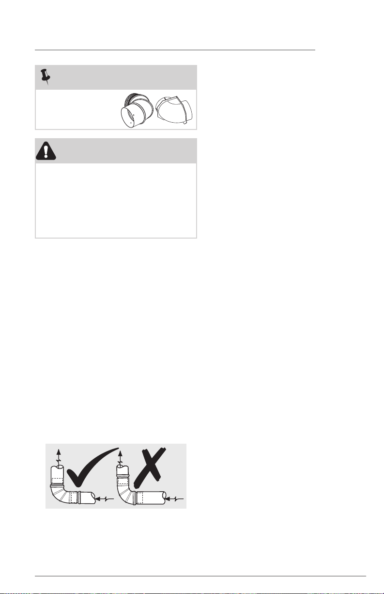
Install male fittings in the correct direction
17
Although vertical orientation of the exhaust
system is acceptable, certain extenuating
circumstances could affect the performance
of the laundry center:
• Only rigid metal duct work should be
used.
• Venting vertically through a roof may
expose the exhaust system to down
drafts causing an increase in vent
restriction.
• Running the exhaust system through
an uninsulated area may cause
condensation and faster accumulation
of lint.
• Compression or crimping of the exhaust
system will cause an increase in vent
restriction.
• The exhaust system should be
inspected and cleaned a minimum of
every 18 months with normal usage. The
more the dryer is used, the more often
you should check the exhaust system
and vent hood for proper operation and
that it is free of obstructions.
Manufactured or Mobile Home
Installation
1. Installation MUST conform to current
Manufactured Home Construction &
Safety Standard, Title 24 CFR, Part 3280 or the Standard For Mobile Homes,
CAN/CSA-Z240 MH.
2. The laundry center MUST be exhausted
outside (outdoors, not beneath the
mobile home) using metal ducting that
will not support combustion. Metal
ducting must be 4 inches (10.16 cm) in
diameter with no obstructions. Rigid
metal duct is preferred.
3. If the laundry center is exhausted
through the floor and area beneath the
mobile home is enclosed, the exhaust
system MUST terminate outside the
enclosure with the termination securely
fastened to a non-combustible portion
of the mobile home structure.
4. Refer to previous sections in this
manual for other important exhaust
venting system requirements.
5. When installing a gas laundry center
Page 18
18
PREINSTALLATION REQUIREMENTS
into a mobile home, a provision must
be made for outside make up air. This
provision is to be not less than twice
the area of the dryer exhaust outlet.
6. Installer MUST anchor this gas laundry
center or to the floor with approved
Mobile Home Installation Kit - P/N
137067200.
Clearance Requirements
IMPORTANT
DO NOT INSTALL YOUR LAUNDRY
CENTER:
• In an area exposed to dripping water
or outside weather conditions. The
ambient temperature should never
be below 60° F (15.6° C) to maximize
detergent effectiveness.
• In an area where it will come in contact
with curtains, drapes, or anything that
will obstruct the flow of combustion and
ventilation air.
• In an area where gasoline or other
flammables are kept or stored.
• On carpet. Floor MUST be solid with
a maximum slope of 1 inch (2.5 cm).
To minimize vibration or movement,
reinforcement of the floor may be
necessary.
• Do not install laundry center on
pedestal.
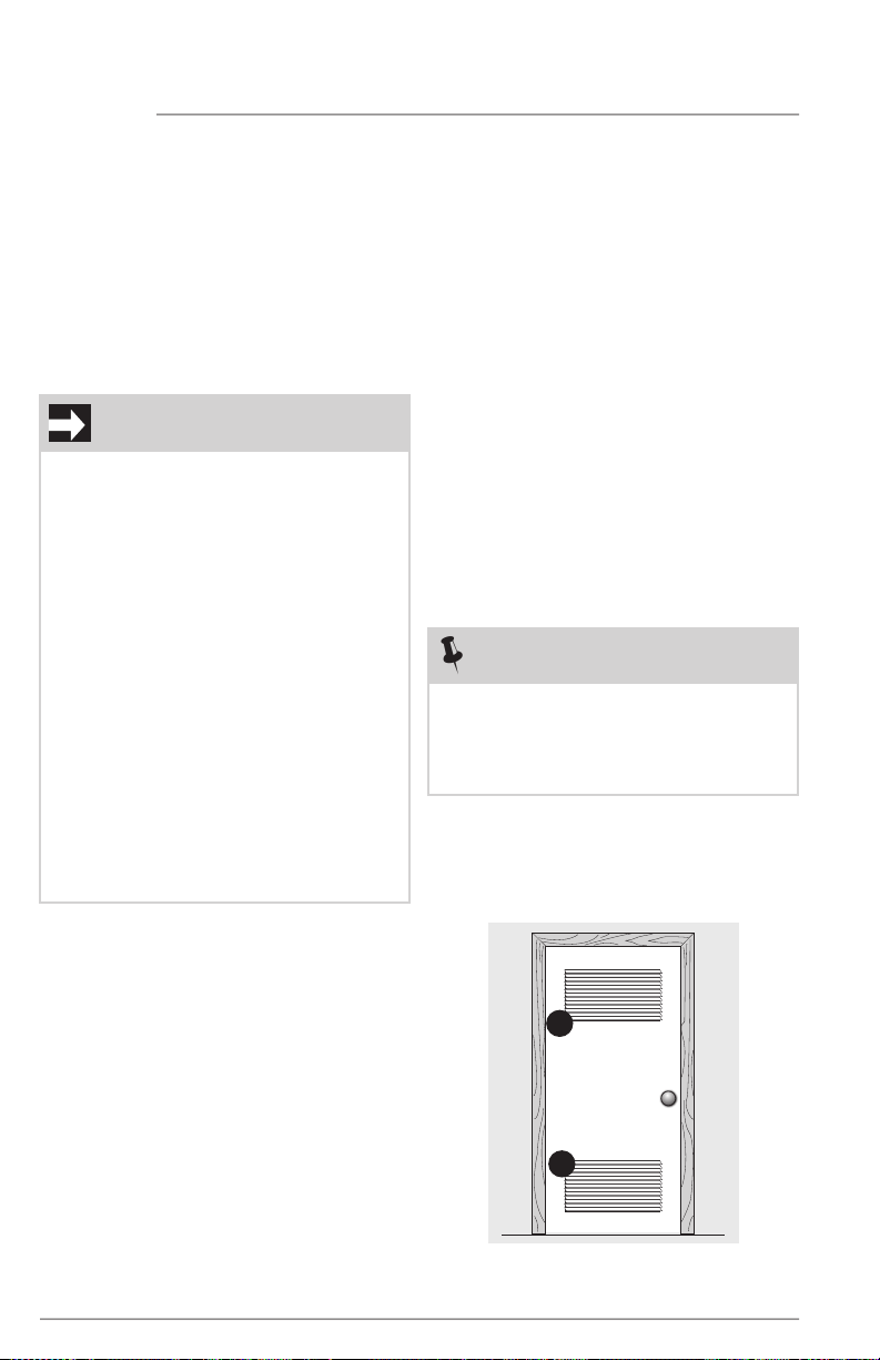
5. Inlet air ventilation to the recess or
closet can be satisfied by adding 120
square inches of opening, equally
divided at the top and bottom of the
door and located 3 inches from the
bottom and top of the door.
or, adding 120 square inches of
ventilation openings to the top, sides
or rear wall of the closet wall, if the wall
is adjacent to an open room, hallway,
or exterior.
or, a louvered door with equivalent air
openings equaling 120 sq. inches of
ventilation for the full length of the door
is acceptable.
It is NOT approved to derive the 120
sq. inches of ventilation from the space
between the door edges and the
casing or the floor.
** The presence of forced heating and
air-conditioning vent openings in the
closet does NOT satisfy the 120 square
inch ventilation requirement to the
closet.
NOTE
To achieve an installation with 0” (0 cm)
clearance for the back of the dryer (for
other than straight back venting), a quickturn 90° dryer vent elbow must be installed
as described previously in this manual.
F
or other than straight back venting, a quickturn 90° dryer vent elbow must be installed to
achieve 0” (0 cm) installation.
Ventilation Examples
Installation In a Recess or
Closet
1. A laundry center installed in a recess or
closet MUST be exhausted outdoors.
2. No other fuel burning appliance shall
be installed in the same recess or closet
as a gas laundry center.
3. Your laundry center needs space
around it for proper ventilation. See
the“Clearance Requirements” chart.
4. A minimum of 120 square inches of inlet
ventilation opening to the recess or
closet is required for proper air flow to
the laundry center.
1
1
1. 120 sq inches equally divided (60 sq in.) split
vent door
Page 19
PREINSTALLATION REQUIREMENTS
2
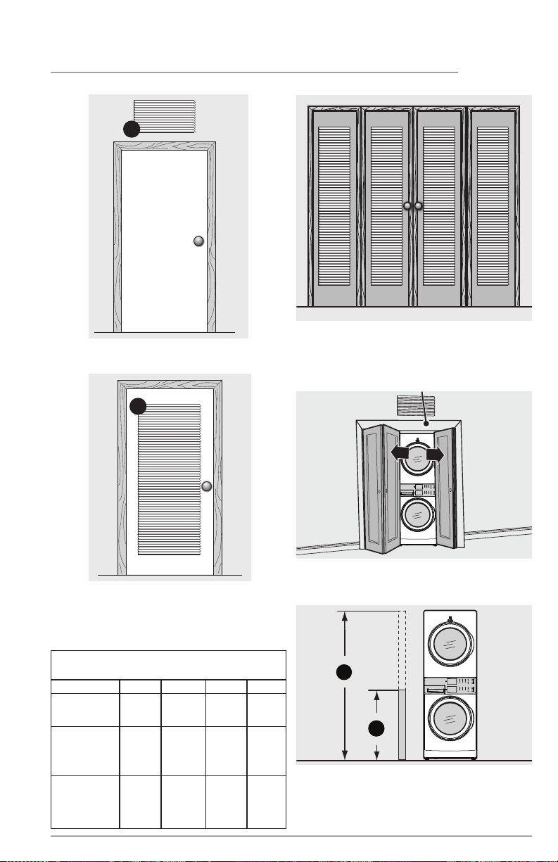
2. Solid Door with 120 sq Wall Ventilation
3
19
Bi-Fold louvered doors with 120 sq. in of
ventilation
120 sq. Inches of wall venting
3. Louvered Door with 120 sq. Inches min.
Louvered Opening
MIN. INSTALLATION CLEARANCES -
Alcove/
recess
Closet with
door vent
Closet with
wall vent
Inches (cm)
Sides Rear Top Front
0"
(0 cm)0"(0 cm)0"(0 cm)
0"
(0 cm)0"(0 cm)0"(0 cm)1"(2.5 cm)
1"
(2.5 cm)1"(2.5 cm)1"(2.5 cm)1"(2.5 cm)
Open
Solid Bi-Fold doors with no ventilation requires
door open for
120 sq. Inches of wall venting
1
2
1. 96” (244cm) max.
2. 24” (61 cm) min.
Page 20
20
7
PREINSTALLATION REQUIREMENTS
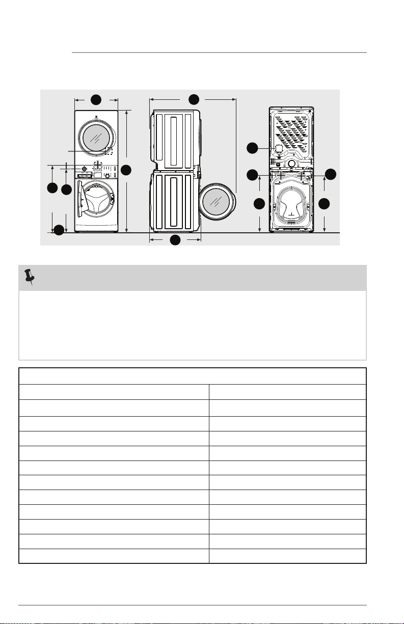
Laundry Center Dimensions
1
†
5
3
2
4
† Dryer electrical supply on rear of unit.
6
12
8
9
11
10
NOTE
• Allow minimum 36” of depth space for proper installation with 90° quick turn elbow for venting.
• Connection of water inlet hose on steam laundry center adds 3/4 in. (2 cm) to installation
depth.
• Power supply cord length on washer approximately 60 inches (152.5 cm).
• Drain hose length on washer approximately 59 inches (150 cm).
• Power supply cord length on gas laundry center or electric Canadian laundry center
approximately 60 inches (152.5 cm).
Laundry Center Dimensions
1. Unit width 27” (69 cm)
2. Height to gas supply pipe on rear of gas unit 39.7” (101 cm)
3. Centerline height for rear vent 41.8” (106 cm)
4. Floor line --
5. Unit height 76.3” (194 cm)
6. Door clearance 53.9” (137 cm)
7. Unit depth 31.9” (81 cm)
8. Width distance to water connections 7.8” (20 cm)
9. Height to water connections 35.7” (91 cm)
10. Height to washer power connections 35.5” (91 cm)
11. Width distance to washer power connections 7.1” (18 cm)
12. Height to dryer electrical supply 48” (122 cm)
Page 21
INSTALLATION
21
Unpacking the Laundry
Center
CAUTION
EXCESSIVE WEIGHT HAZARD
It is best for two people to work as a team to
move or lift the laundry center to avoid injury.
WARNING
Do not allow the unit to fall when tipping
to remove packing materials.
IMPORTANT
Save the foam base and shipping plug to
help prevent damage during any future
moves.
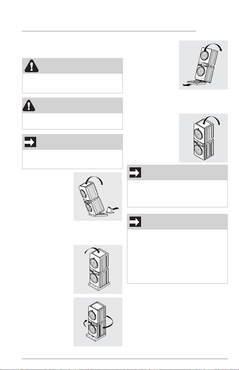
1. Tape dryer
and washer
doors closed.
A person must
stand in front
and rear of unit.
Tilt unit forward.
Front person
must hold
unit while rear
person removes Styrofoam support
from underneath the interior of the
washing machine.
2. Return unit
to original
position.
4. Maintaining a
hold the unit
at all times,
tilt backward
so the bottom
rear of the unit
contacts the
floor. Have the
rear person
hold unit while
the person in front person removes the
Styrofoam pad from underneath the
unit.
5. Tilt unit forward
to standing
position on
floor.
IMPORTANT
• DO NOT place the laundry center onto its
back without the shipping bolts.
DO NOT tip washer upside down onto
its top or right side for any reason.
IMPORTANT
Failure to remove shipping hardware
completely could result in damage to
the appliance, damage to your home, or
unexpected washing results.
Save all shipping bolts and spacers
for future use. If the washer is to be
transported at a later date, the shipping
hardware must be reinstalled to help
prevent shipping damage
3. The people in
front and rear
of the unit must
hold the base
pad in place
while walking
the unit towards
the rear of the
Styrofoam pad
until both rear
feet of the unit are firm on the ground.
Page 22
22
INSTALLATION
Decoupling the Laundry Center
(if Needed)
This Laundry Center can be disassembled
in special cases, such as to aid with moving
through the house and final installation
or during removal. If decoupling is not
necessary, skip these steps and proceed to
the Installing the Hole Plugs section.
NOTE
The units will not work separately when
disassembled and must be re-assembled
when final installation is complete.
WARNING
• Disassembling this Laundry Center must
be performed by a service agency or
qualified installers.
• This operation requires at least 2
people to move or lift the units. Do not
disassemble or repair this Laundry Center
by yourself.
• Use safety protective items such as
glasses, gloves, sleeves and shoes to
reduce the risk of injuries.
• ALWAYS DISCONNECT BOTH POWER
SUPPLIES BEFORE SERVICE OR REPAIR.
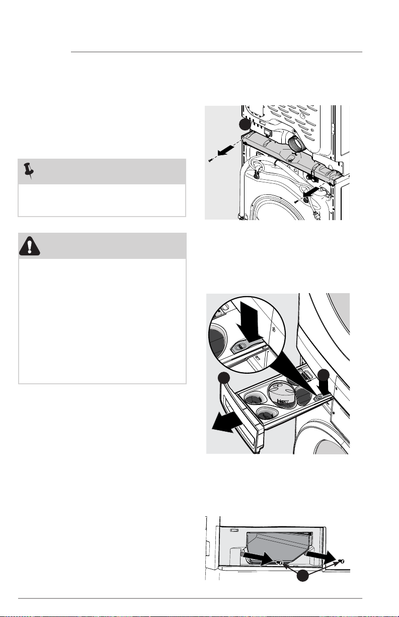
3. Remove the two screws on the back
of the Laundry Center to disconnect
the dryer from the rear bracket. Do not
remove the bracket.
3
3. Rear Bracket
4. Pull the drawer out until it stops.
5. Press down firmly on the lock tab in the
right rear corner of the dispenser cavity
to release, then pull out the drawer.
4
5
1. Use the tools listed in the PreInstallation Requirements section of
this Use & Care Manual.
2. Prepare the work area. Use protective
products designed to protect the floor
against water and scratches while
handling the units.
4. Dispenser Drawer
5. Lock Tab
6. Unscrew the two screws in the
dispenser housing to remove.
6
6. Dispenser screws
Page 23
INSTALLATION
23
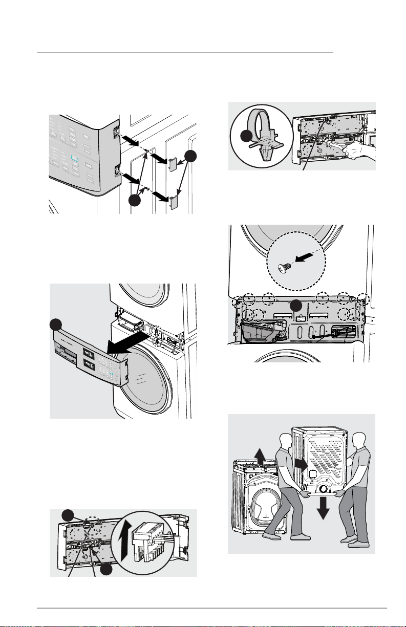
7. Unsnap the two plastic tabs on both
sides of the control panel.
8. Remove the two screws on both sides
of the control panel.
8
7. Plastic screw tabs
8. Control panel screws
9. Pull the control panel forward to
remove.
9
12. Use curved-nose pliers to disconnect
the dryer harness clip from the control
panel.
12
7
12. Dryer harness clip
13. Remove the ten screws securing the
front bracket in place to disconnect the
dryer from the front bracket.
13
9. Control panel
10. Disconnect the washer wiring harness
from the control panel.
11. Disconnect the dryer wiring harness
from the control panel.
11
10
10. Washer harness
11. Dryer harness
13. Front Bracket
14. With at least two persons, carefully lift
the dryer and set it down on the floor.
15. The laundry center can now be moved
to the final installation location.
16. Reverse the steps to re-assemble the
Laundry Center.
Page 24
24
INSTALLATION
Removing Shipping Hardware
1
2
3
4
2
3
4
1
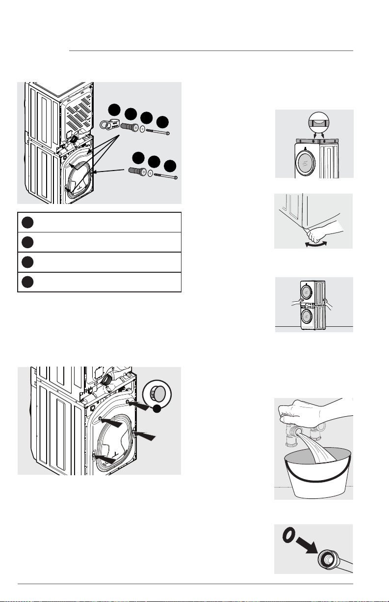
3 P Clamps
2
4 Black Spacers
3
4 Shims
4
4 Bolts
Installing Hole Plugs
Locate the 4 hole plugs in the small bag
supplied with the laundry Center instruction
manuals. Insert them in the holes in the
washer back panel where the shipping
hardware has been removed.
Leveling the Laundry Center
Excessive noise and vibration can be
prevented by properly leveling the laundry
center.
1. Place a level
on top of the
laundry center
with the unit
within 3 ft (1
m) of the final
location for
free standing
installation.
2. Use an
adjustable
wrench to adjust
the leveling legs
so the unit is
stable cornerto-corner and
level front-to-back and side-to-side,
and.
3. Press down
on alternate
corners and
sides and feel
for the slightest
movement.
Adjust the
appropriate leg(s) so the unit sits solidly
on the floor on ALL four legs. Keep the
leveling leg extension at a minimum for
best performance of the laundry center.
1. Hole Plug x 4
Connecting the Water
1
1. Run some
water from the
hot and cold
faucets to flush
the water lines
and remove
particles that
might clog the
water valve
screens and
to determine
which faucet is
hot and which is cold supply.
2. Check to ensure
that the inlet
hoses have the
rubber washer
firmly in place.
Page 25
1
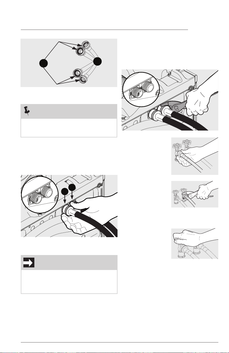
1. Rubber washers must be present
2. Use only new hoses
2
NOTE
Hoses are not included with Laundry
Center purchase.
3. Connect the HOT inlet hose to the
HOT inlet connection (red) and the
COLD inlet hose to the COLD inlet
connection (blue) on the laundry
center.
INSTALLATION
4. Tighten by hand until snug. Then
tighten each supply connection
another 2/3 turn with pliers.
Do not cross thread or over-tighten
these connections.
5. Connect the
HOT inlet hose
to the HOT water
supply and the
COLD inlet hose
to the COLD
water supply.
25
2
1
1. Cold Inlet
2. Hot Inlet
IMPORTANT
The cold water inlet will have a blue cap
cover on the inlet connection and the hot
water inlet will have a red cap cover on
the inlet connection.
6. Tighten by
hand until snug.
Then tighten
each supply
connection
another 2/3 turn
with pliers. Do not bend, kink or pinch
water inlet hoses.
7. Turn on the
water and check
for leaks.
Page 26
26
INSTALLATION
Connecting the Drain
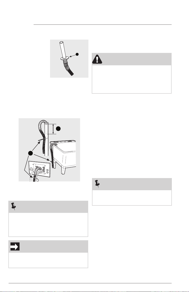
1. Verify the antisiphon disc is in
place.
2. Form a “U”
shape on the
end of the drain
hose with the
hose pointed
toward the
drain. Place
the formed end
in a laundry tub or a standpipe and
secure the drain hose with the cable
tie (provided in the manual bag) to the
standpipe, inlet hose, laundry tub, etc.
so the hose does not pull out from the
force of the water.
2
1. Anti-Siphon Disc
1
Completing the Installation
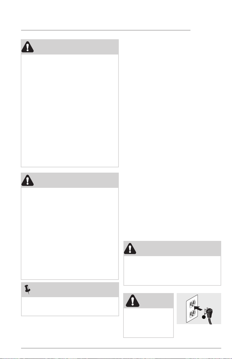
1. Plug the power cord into a grounded
outlet.
1
WARNING
ELECTRICAL SHOCK HAZARD
Improper connection of the equipment
grounding conductor can result in a risk
of electrical shock. Check with a licensed
electrician if you are in doubt as to whether
the appliance is properly grounded.
2. Turn on the power at a circuit breaker/
fuse box.
3. Carefully slide the washer to its final
position. Recheck for level and rock
corners for stability. See
laundry center.
door tape.
4. Run the washer through a complete
cycle, checking for water leaks and
proper operation.
5. If you have any questions during
initial operation, please review the
Troubleshooting
for service.
6. Place these instructions in a location
near the washer for future reference.
Remove and discard
Leveling the
section before calling
1. Insert less than 8.5” (21.5cm).
2. Cable tie
NOTE
The standpipe inside diameter must be
1-1/4” (3.2 cm) minimum. There must be
an air gap around the drain hose in the
standpipe. A snug hose fit can cause a
siphoning action.
IMPORTANT
Check to ensure the power is off at a
circuit breaker/fuse box before plugging
the power cord into an outlet.
NOTE
A wiring diagram and technical data
sheet are located behind the control
panel.
Connecting the Electrical
System
The following are specific requirements for
proper and safe electrical installation of
your laundry center. Failure to follow these
instructions can create electrical shock and/
or a fire hazard.
Page 27
INSTALLATION
27
WARNING
ELECTRICAL SHOCK HAZARD
• This appliance MUST be properly
grounded. Electrical shock can result
if the laundry center is not properly
grounded. Follow the instructions in this
manual for proper grounding.
DO NOT use an extension cord with
this laundry center. Some extension
cords are not designed to withstand
the amounts of electrical current this
laundry center utilizes and can melt,
creating electrical shock and/or fire
hazard. Locate the laundry center
within reach of the receptacle for the
length power cord to be purchased,
allowing some slack in the cord. Refer
to the
Pre-Installation Requirements
this manual for the proper power cord
to be purchased.
section of
WARNING
ELECTRICAL SHOCK HAZARD
• A U.L.-approved strain relief must be
installed onto power cord. If the strain
relief is not attached, the cord can
be pulled out of the dryer and can
be cut by any movement of the cord,
resulting in electrical shock.
DO NOT use an aluminum wired
receptacle with a copper wired
power cord and plug (or vice versa).
A chemical reaction occurs between
copper and aluminum and can cause
electrical shorts. The proper wiring and
receptacle is a copper wired power
cord with a copper wired
receptacle.
NOTE
For a Grounded, Cord-connected
Laundry Center:
1. The laundry center MUST be grounded.
In the event of a malfunction or
breakdown, grounding will reduce the
risk of electrical shock by providing a
path of least resistance for electrical
current.
2. After you purchase and install a 3-wire
or 4-wire power supply cord having
an equipment-grounding conductor
and a grounding plug that matches
your wiring system, the plug MUST be
plugged into an appropriate, copper
wired receptacle that is properly
installed and grounded in accordance
with all local codes and ordinances. If
in doubt, call a licensed electrician.
3. DO NOT modify the plug you’ve
installed on this appliance. If it will
not fit the outlet, have a proper outlet
installed by a qualified electrician.
For a Permanently Connected
Laundry Center:
The laundry center MUST be connected to a
grounded metal, permanent wiring system;
or an equipment grounding conductor
must be run with the circuit conductors and
connected to the equipment-grounding
terminal or lead on the appliance.
Grounding Requirements -
Electric Laundry Center (Canada)
WARNING
Improper grounding of the laundry center
may cause serious injury or death. Check
with a licensed electrician if you are in
doubt as to whether the appliance is
properly grounded.
Dryers operating on 208 volt power supply
will have longer drying times than dryers
operating on 240 volt power supply.
The laundry center, when installed, must be
electrically grounded in accordance with
local codes and the National Electrical code
ANSI/NFPA 70 or the Canadian Electrical
Code, Part 1, CSA C22.1.
CAUTION
Do not, under any
circumstances, cut,
remove, or bypass
the grounding
prong.
1
1. Power cord with
grounded prong.
Page 28
28
INSTALLATION
Electrical Connection
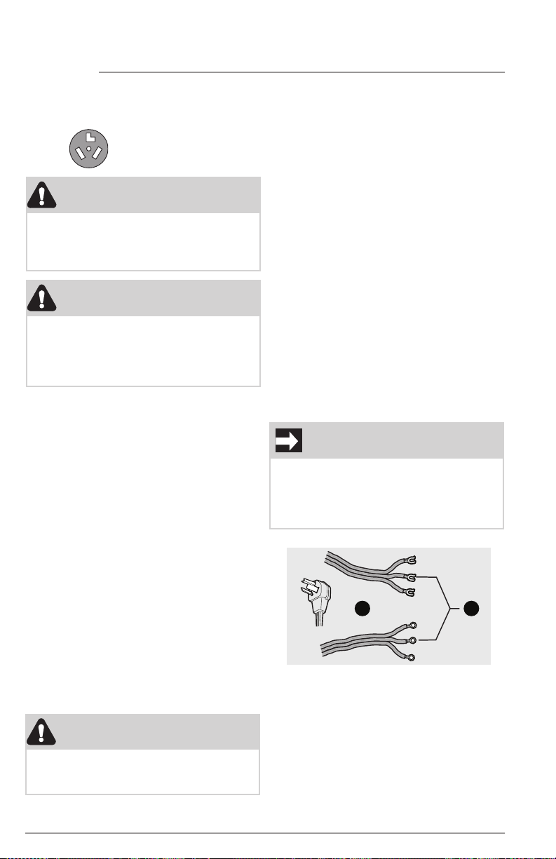
(non-Canada) - 3 wire cord
3-wire receptacle
(NEMA type 10-30R)
WARNING
ELECTRICAL SHOCK HAZARD
Failure to disconnect power source before
servicing could result in personal injury or
even death.
WARNING
Label all wires prior to disconnection when
servicing controls. Wiring errors can cause
improper and dangerous operation. Verify
proper operation after servicing.
1. Turn off power supply to outlet.
2. Remove the screw securing the
3. Install a UL-approved strain relief
4. Thread an UNPLUGGED, UL-approved,
5. Attach the power cord neutral (center
6. Attach the remaining two power cord
ELECTRICAL HAZARD
terminal block access cover in the
lower corner on the back of the
laundry center.
according to the power cord/strain
relief manufacturer’s instructions in
the power cord entry hole below the
access panel. At this time, the strain
relief should be loosely in place.
30 amp. power cord, NEMA 10-30 type
SRDT, through the strain relief.
wire) conductor to the SILVER colored
center terminal on the terminal block.
Tighten the screw securely.
outer conductors to the outer, BRASS
colored terminals on the terminal
block. Tighten both screws securely.
7. Follow manufacturer’s guidelines for
firmly securing the strain relief and
power cord.
8. Reinstall the terminal block cover.
Grounding Requirements -
Gas Dryer
1. The dryer is equipped with a three-
prong (grounding) plug for your
protection against shock hazard
and should be plugged directly into
a properly grounded three-prong
receptacle.
2. The plug must be plugged into an
appropriate outlet that is properly
installed and grounded in accordance
with all local codes and ordinances. If
in doubt, call a licensed electrician.
3. DO NOT modify the plug provided with
this appliance. If it will not fit the outlet,
have a proper outlet installed by a
qualified electrician.
IMPORTANT
If moving laundry center from a 4-wire
system and installing it in a 3-wire system,
move the internal ground from the center
terminal back to the GREEN screw next to
the terminal block.
1 2
1. Rubber washers must be present.
2. Use only new hoses.
WARNING
ELECTRICAL SHOCK HAZARD
DO NOT make a sharp bend or crimp
wiring/conductor at connections.
Page 29
INSTALLATION
29
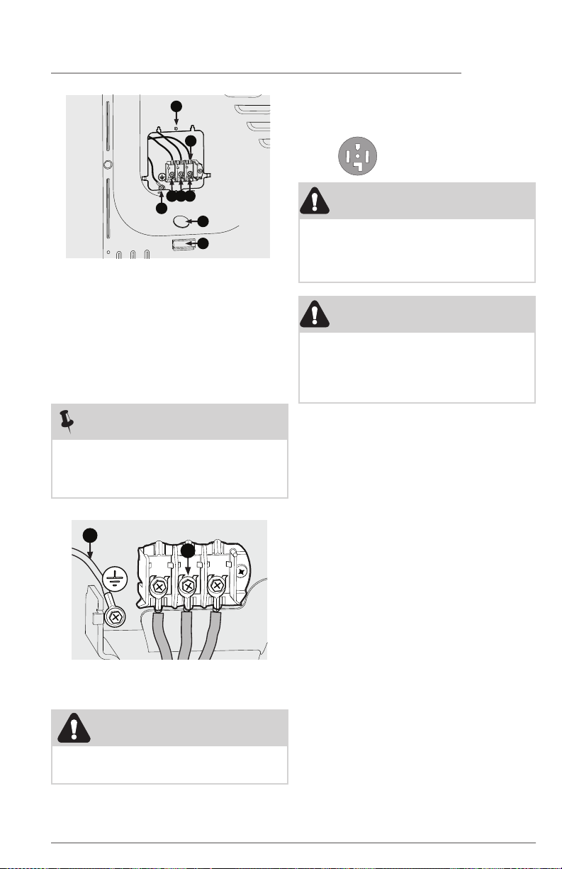
1
324
5
6
7
8
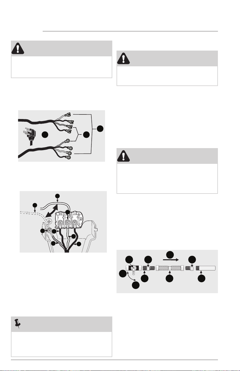
1. Access Cover Screw
2. Terminal Block
3. Line 2 (BRASS Terminal)
4. Neutral (SILVER Terminal)
5. Line 1 (BRASS Terminal)
6. Internal Ground (GREEN Screw)
7. Install UL-Approved Strain Relief Here
8. Terminal Screw Recovery Slot
NOTE
If a terminal screw falls during cord
installation, it can be retrieved in the
terminal screw recovery slot below the
access panel.
1
2
1. Internal Ground
2. Neutral Terminal
CAUTION
DO NOT remove an internal ground from
a 3-wire system
Electrical Connection
(non-Canada) - 4 Wire Cord
4-wire receptacle
(NEMA type 14-30R)
WARNING
ELECTRICAL SHOCK HAZARD
Failure to disconnect power source before
servicing could result in personal injury or
even death.
WARNING
Label all wires prior to disconnection when
servicing controls. Wiring errors can cause
improper and dangerous operation. Verify
proper operation after servicing.
1. Turn off power supply to outlet.
2. Remove the screw securing the terminal
block access cover in the lower corner on
the back of the laundry center.
3. Install a UL-approved strain relief
according to the power cord/strain relief
manufacturer’s instructions in the power
cord entry hole below the access panel.
At this time, the strain relief should be
loosely in place.
4. Thread an UNPLUGGED, UL-approved,
30 amp. power cord, NEMA 14-30 type
DRT or SRDT, through the strain relief.
5. Disconnect the internal (WHITE) dryer
harness ground wire from the (GREEN)
ground screw next to terminal block.
6. Attach the ground (GREEN) power cord
wire to the cabinet with the ground
(GREEN) screw. Tighten the screw
securely.
7. Move the internal dryer harness ground
(WHITE) wire to the terminal block and
attach it along with the neutral (WHITE)
power cord wire conductor to center,
SILVER colored terminal on the terminal
block. Tighten the screw securely.
8. Attach the RED and BLACK power cord
conductors to the outer, BRASS colored
terminals on the terminal block. Tighten
both screws securely.
ELECTRICAL HAZARD
Page 30
30
INSTALLATION
WARNING
ELECTRICAL SHOCK HAZARD
DO NOT make a sharp bend or crimp
wiring/conductor at connections.
9. Follow manufacturer’s guidelines for firmly
securing the strain relief and power cord.
10. Reinstall the terminal block cover.
3
21
1. 30 AMP NEMA 14-30
2. Ground (GREEN wire)
3. Neutral (WHITE wire)
2
1
3
8
6
7
4
5
Connecting the Gas
WARNING
Adjustments to the gas burner should
only be performed by qualified service
personnel.
This gas laundry center comes from the factory
with natural gas burner components installed.
DO NOT operate this gas laundry center, using
LP (liquid propane) gas, unless the LP gas
conversion kit has been properly installed by
a qualified service personnel. Improper gas
installation or LP conversion kit installation
could result in injury or even death.
1. Remove the shipping cap from gas
pipe at the rear of the laundry center.
WARNING
DO NOT connect the laundry center to
L.P. gas service without converting the gas
valve. An L.P. conversion kit PN# PCK4200
(not included) must be installed by a
qualified gas technician.
2. Connect a 1/2 inch (1.27 cm) I.D.
semi-rigid or approved pipe from
gas supply line to the 3/8 inch (0.96
cm) pipe located on the back of the
laundry center. Use a 1/2 inch to 3/8
inch (1.27 cm to 0.96 cm) reducer for the
connection. Apply an approved thread
sealer that is resistant to the corrosive
action of liquefied gases on all pipe
connections.
1. Internal ground (WHITE) initial location.
2. Move (WHITE) wire to neutral (SILVER)
terminal for 4-wire system).
3. Neutral (SILVER Terminal)
4. WHITE neutral wire
5. BLACK or RED power wire
6. BLACK or RED power wire
7. GREEN ground wire
8. GREEN Ground screw
NOTE
If a terminal screw falls during cord
installation, it can be retrieved in the
terminal screw recovery slot below the
access panel.
5
5
1
1
7
7 8 9
643
98
2
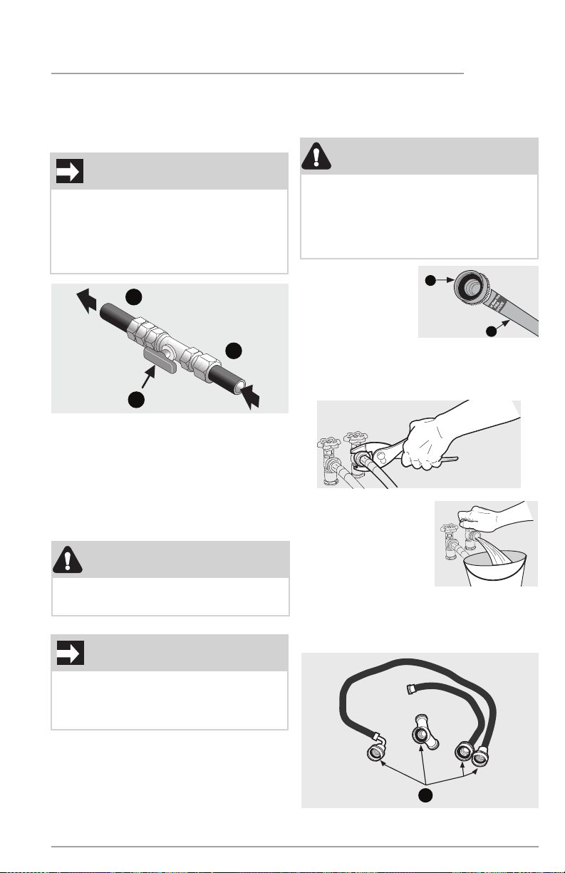
All connections must be wrench-tightened
1. Valve open position
2. Valve closed position
3. Manual Shutoff valve
4. Flare union
5. Gas flow
6. Flare union
7. Nipple
8. Flexible connector
9. Inlet pipe on back of laundry center
Page 31
INSTALLATION
2
1
31
3. Open the shutoff valve in the gas
supply line to allow gas to flow through
the pipe. Wait a few minutes for gas to
move through the gas line.
IMPORTANT
The supply line must be equipped with an
approved manual shutoff valve. This valve
should be located in the same room as the
laundry center and should be in a location
that allows ease of opening and closing. DO
NOT block access to the gas shutoff valve.
1
2
3
1. To dryer connection
2. From Gas supply
3. Shutoff Valve in open position.
4. Check for gas system leaks with a
manometer. If a manometer is not
available, test all connections by
brushing on a soapy water solution.
WARNING
Connecting the Water
(steam models only)
WARNING
Periodically inspect all water inlet hoses
for water leaks, wear, cuts, corrosion and
bulges. Replace all hoses, if any sign of
the above is visible. All hoses should be
replaced every 5 years to reduce the risk
of hose failures.
1. Rubber washer
must be present
and undamaged
2. Cold inlet hose to
washer
1. Remove COLD inlet hose from COLD
water supply and inspect for rubber
washer. Replace washer if it is torn or
worn out.
2. Turn on COLD
supply and run
water to clear any
contaminants in the
line.
1
NEVER test for gas leaks with an open flame.
EXPLOSION HAZARD
IMPORTANT
Installation to the gas service must follow
local codes and ordinances and the latest
edition of the National Fuel Gas Code ANSI
Z223.1/NFPA 54 or in Canada, CSA B149.1.
3. Inspect hose couplings for proper
placement of rubber washers. Use hoses
from ASSEMBLY HOSE KIT# 5304495002
(not included).
1. Rubber washer must be present and
undamaged.
Page 32
32
INSTALLATION
4. If your installation has room for the COLD
water supply to accept the “Y” connector
directly, thread the “Y” connector to the
COLD water supply and snug it by hand;
then tighten it another 2/3 turn with pliers.
NOTE
If you were able to install the “Y”
connector directly to the COLD water
supply, please skip to step 8.
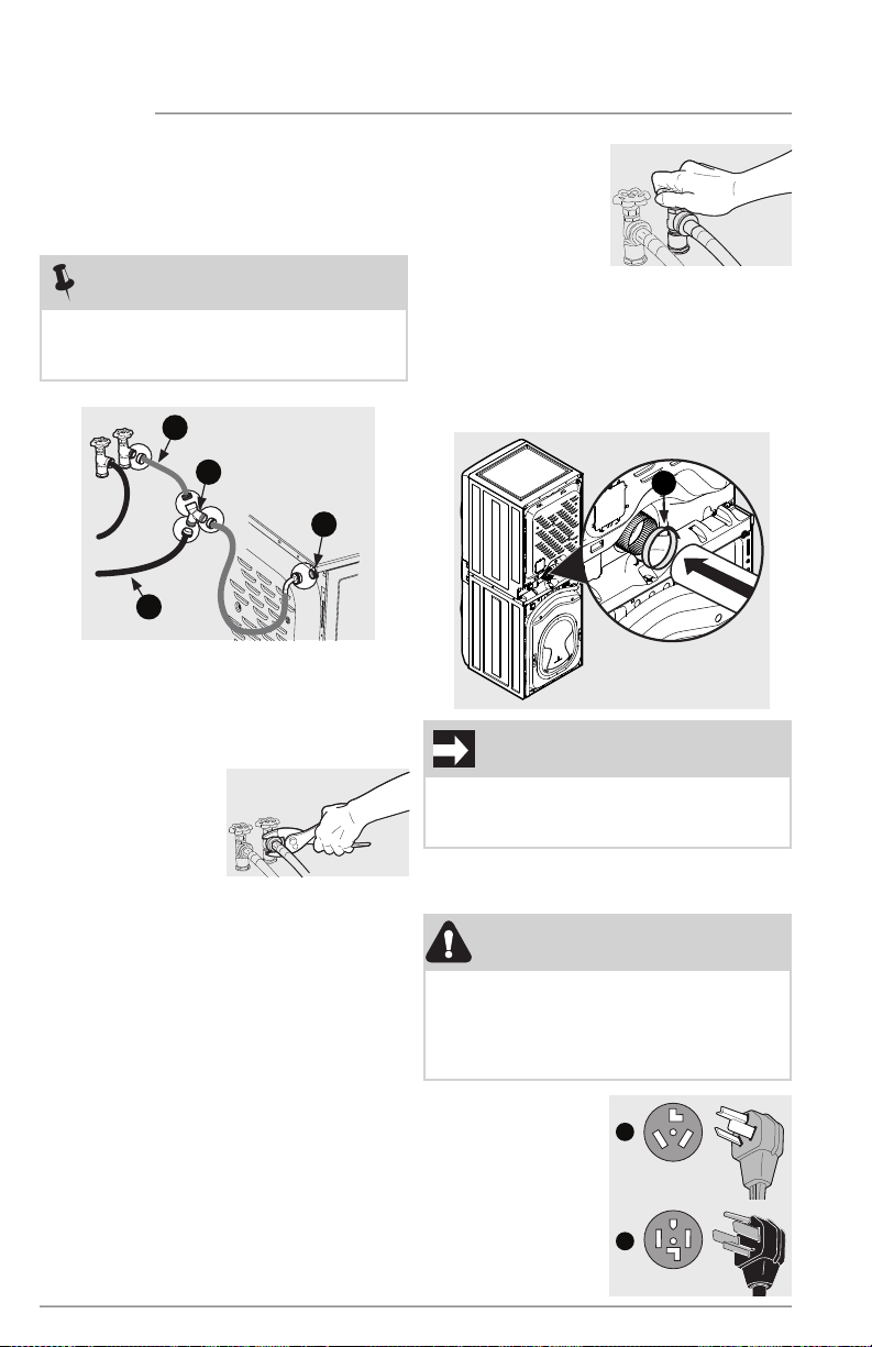
1
2
3
4
1. Short hose
2. “Y” connector
3. Water Inlet on dryer
4. Cold water supply hose to washer
5. If there is not
room to install
the “Y” connector
directly, thread
the short
extension hose
on to the COLD water supply and snug it
by hand; then tighten it another 2/3 turn
with pliers.
6. Thread the “Y” connector to the short
extension hose and snug it by hand; then
tighten it another 2/3 turn with pliers.
7. Connect the COLD inlet hose for the
washer to the “Y” connector and snug it
by hand; then tighten it another 2/3 turn
with pliers.
8. Connect the straight end of the long hose
from the kit to the other outlet on the “Y”
connector and snug it by hand. Connect
the hose’s 90° coupling to the brass
water inlet on the back of the laundry
center and snug it by hand. Tighten
each connection of the dryer inlet hose
another 2/3 turn with pliers.
9. Turn on the
water and check
for leaks at all
connections.
Completing the Installation
1. Connect the exhaust duct to the
outside exhaust system. Use of
a 4” (102 mm) clamp (item A) is
recommended to connect the dryer to
the exhaust vent system. Use metal foil
tape to seal all other joints.
1
IMPORTANT
Be sure the power is off at a circuit
breaker/fuse box before plugging the
power cord into an outlet.
2. Plug the power cord into a grounded
outlet.
WARNING
Improper grounding of the laundry center
may cause serious injury or death. Check
with a licensed electrician if you are in doubt
as to whether the appliance is properly
grounded.
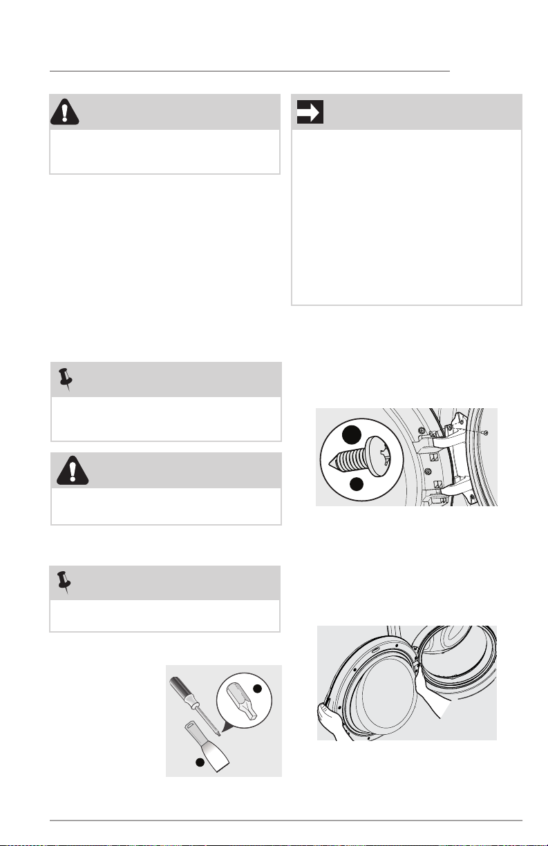
1. 3-Wire Grounded
Plug
2. 4-Wire Grounded
Plug
1
2
Page 33
INSTALLATION
33
WARNING
Do not store combustible materials,
gasoline, and other flammable vapors and
liquids near this laundry center.
3. Turn on the power at the circuit
breaker/fuse box.
4. Read the Use & Care Manual provided
with the laundry center. It contains
valuable and helpful information that
will save you time and money.
5. If you have any questions during initial
operation, please review the “Avoid
Service Checklist” in your Use & Care
Manual before calling for service.
6. Place these instructions in a location
near the laundry center for future
reference.
NOTE
A wiring diagram and technical data sheet
are located behind the console.
CAUTION
Remove the door when discarding or
storing your old laundry center.
Reversing the Washer Door
NOTE
Door reversibility is available on all
models.
IMPORTANT
BEFORE YOU REVERSE WASHER DOOR:
1. Be sure you have adequate swing area
before reversing door.
2. Gather your tools - including a screw driver
with a #2 square bit and plastic knife (or
small, flat prying tool that won’t damage
paint).
3. Protect flat work surface, such as top of
washer or floor near washer, with a soft
cloth or towel.
4. Be sure laundry center is unplugged from
power source!
Removing Washer Door Assembly
1. Completely open the door to expose
all four hinge screws.
2. Remove all four hinge screws with #2
square bit driver. Save for reinstalling later.
x4
1
Remove 4 fine thread screws
3. Hold the door with one hand
supporting the handle area and one
hand supporting the hinge. While
supporting the door at the hinge, press
firmly with the other hand until the
locating pins on the back of the hinge
plate dislocate from the front panel.
Tools Needed for Reversal:
1. Screwdriver with #2
square bit
2. Plastic knife
2
1
Page 34
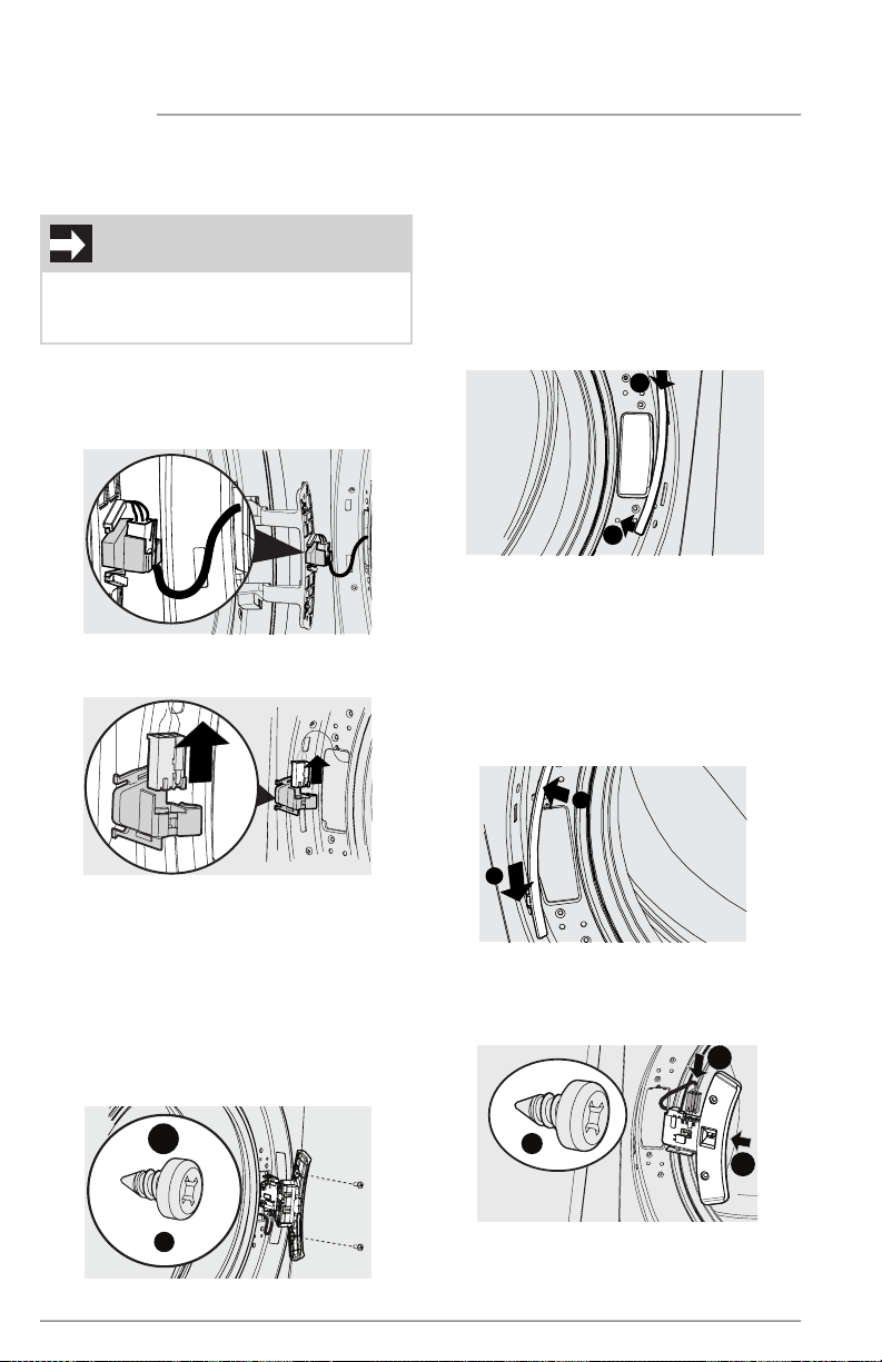
34
1
2
1
INSTALLATION
4. While supporting the door with one
hand, pinch the tabs to release the
plastic terminal cap from the hinge plate.
IMPORTANT
Take care not to pull the door away from
the washer until you remove the wiring
harness terminal cap.
5. Set the door face down on a flat
surface protected by soft cloth or towel.
6. Release wiring harness from retainer
on plastic terminal cap.
7. Then release terminal from terminal
cap. Save the cap to reinstall later.
3. Disconnect the wiring harness
terminal from the door lock. Set the
door lock aside for re-installation later.
4. Pry the bottom of the plastic hole
cover upward to release it from the
front panel. You may have to use a
non-scratching plastic knife if you are
unable to release it manually. Then,
slide the cover down slightly and
remove it from the front panel.
2
1
Reinstalling Washer Door Lock
and Hole Cover
1. Move the plastic cover to the other side
of the front panel. Position the cover so
the “hook” is at the bottom. Insert hook
into lower slot, slide the cover down,
and press upper retention tabs into
opening until they snap into place.
Removing Washer Door Lock and
Plastic Hole Cover
1. Locate and remove both screws from
door lock. Save screws for later.
2. Rotate the lock as you pull it out
through the front panel. Take care not
to pull too hard or too far as the lock is
still attached to the wiring harness.
x2
1
Remove coarse thread screw
2. Insert wiring harness into door lock.
3. Insert door lock into front panel and
reinstall door lock screws.
3
2
Reinstall coarse thread screw
Page 35
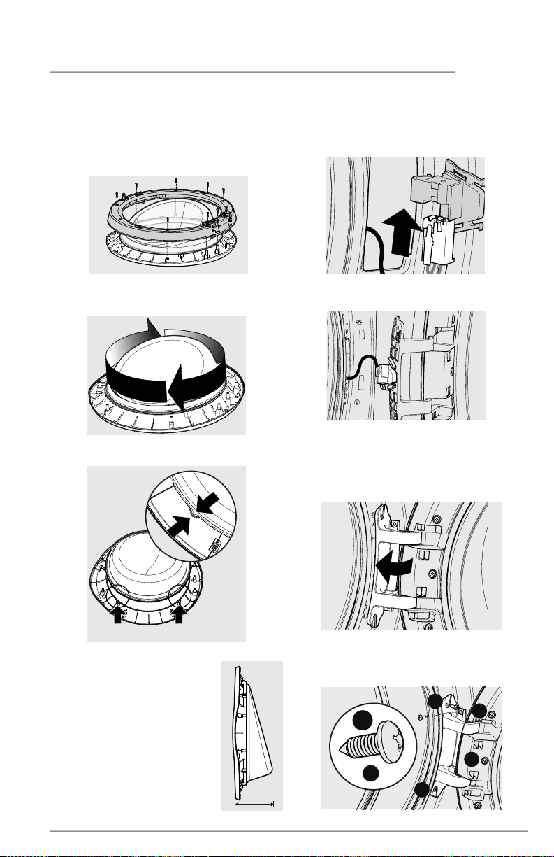
INSTALLATION
35
Reversing Washer Door Assembly
1. Locate nine screws on inner door
ring. Remove each and save for reinstallation later. Remove inner door
(with hinge) and carefully set aside.
2. Lift door bowl slightly and rotate 180
degrees, setting it back onto outer door.
3. Make sure the alignment tabs reengage.
Reinstalling Washer Door Assembly
1. Insert the wiring harness terminal into
the terminal cap and wrap the harness
into the harness retainer.
2. Slide terminal cap onto back of hinge
plate until tabs snap into place.
3. Insert hinge locating pins into the hole
that were previously covered by the
plastic hole cover. Press on the face of
the hinge to snap the other locating
pins into place.
Connect to Notches
4. Reattach the inner door
to the outer door using
the nine screws removed
earlier. See illustration,
Step 1.
5. Check to verify that the
scoop (wider section) of
the door bowl is situated at
the BOTTOM of the door.
4. Reinstall all four screws removed earlier
- two front screws first, then two side
screws.
1
x4
3
4
5
2
Reinstall fine thread screw
Page 36
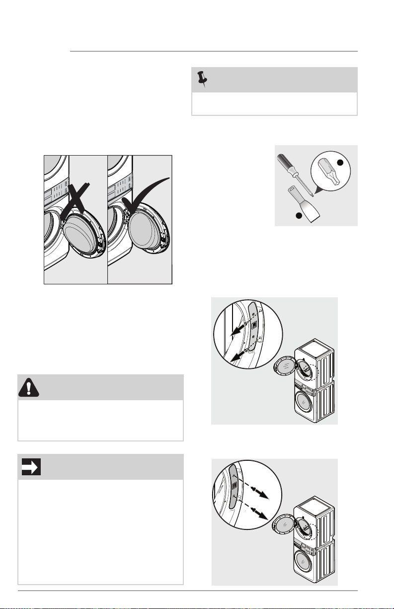
36
INSTALLATION
Verify Reversed Washer Door
Operation
1. Test door for free, smooth swinging
operation and secure latching when
closed.
2. Verify inner door bowl is in the correct
orientation with the “scoop” at the
bottom.
3. Plug in washer and close the door. Test
correct door lock operation by starting
a test cycle: lock should engage, and
door should not be able to be opened
until cycle is paused or canceled.
NOTE
Door reversibility is available on all
models.
Tools Needed for Dryer Door
Reversal:
1. Screwdriver with
#2 square bit
2. Plastic knife
2
1
Removing Latch and Hole Plugs
1. Open the door.
2. Remove plastic hole plugs and save to
reinstall later. You may have to use a
non-scratching plastic knife if you are
unable to dislodge the plugs manually.
Reversing the Dryer Door
WARNING
FIRE HAZARD
Failure to Follow these instructions may
result in a fire hazard. All steps must be
followed.
IMPORTANT
BEFORE YOU REVERSE YOUR DRYER
DOOR:
1. Be sure you have adequate swing area
before reversing door.
2. Gather your tools - including a screw
driver with a #2 square bit and plastic
knife (or small, flat prying tool that won’t
damage paint).
3. Be sure laundry center is unplugged
from power source!
3. Remove both screws from door
latch. Save latch and screws for reinstallation later.
Page 37
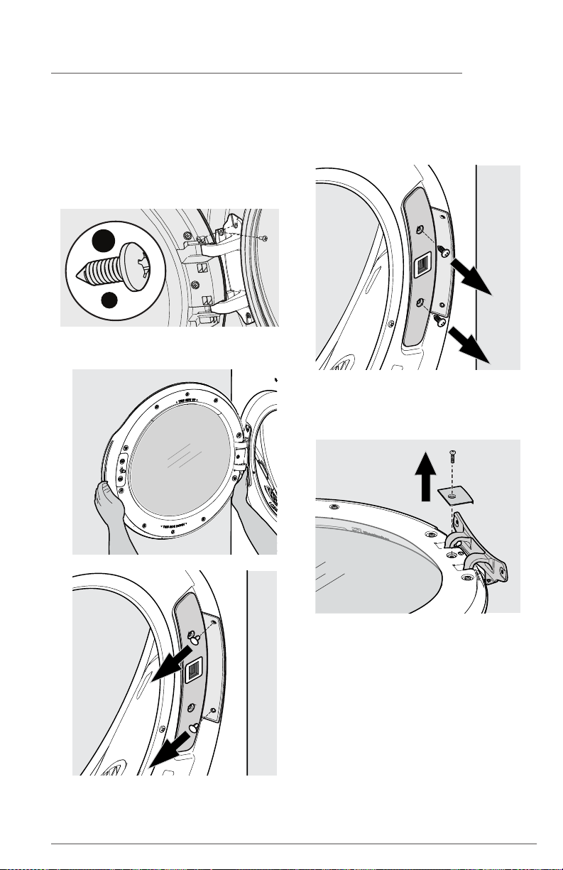
INSTALLATION
37
Removing Dryer Door Assembly
1. Open the door and remove screws
with #2 square bit drive. Save for
reinstallation.
2. Remove the door assembly and place
on a cloth or towel on a flat surface.
x4
1
3. Remove the decorative caps from the
front panel and save for reinstallation.
Reversing Dryer Door Assembly
1. Locate and remove the two screws
securing the latch. Save the screws
and latch for reinstallation.
2. Locate and remove the screw holding
the hinge cover. Save the screw and
cover for reinstallation.
Page 38
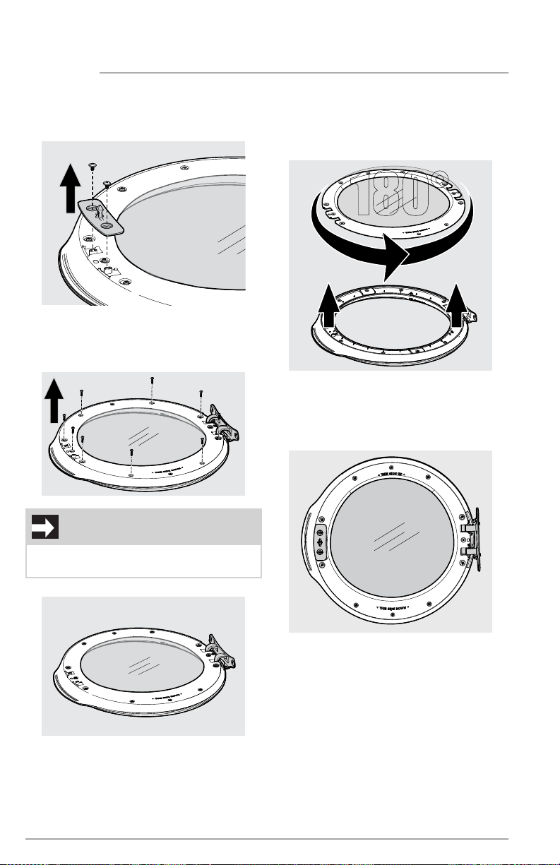
38
X
180°
INSTALLATION
3. Locate and remove the two screws
holding the striker. Save the screws
and latch for reinstallation.
4. Remove remaining eight screws using
a #2 square bit driver. Save the screws
for reinstallation.
5. Lift the metal ring and rotate it
180 degrees, setting it back on the
inner frame. Ensure gasket has not
separated from the metal ring.
6. Make sure “THIS SIDE UP” AND “THIS
SIDE DOWN” on the metal ring point in
the corresponding directions.
IMPORTANT
Do not remove the torque screws at the
twelve and 6 o’clock positions.
X
Page 39
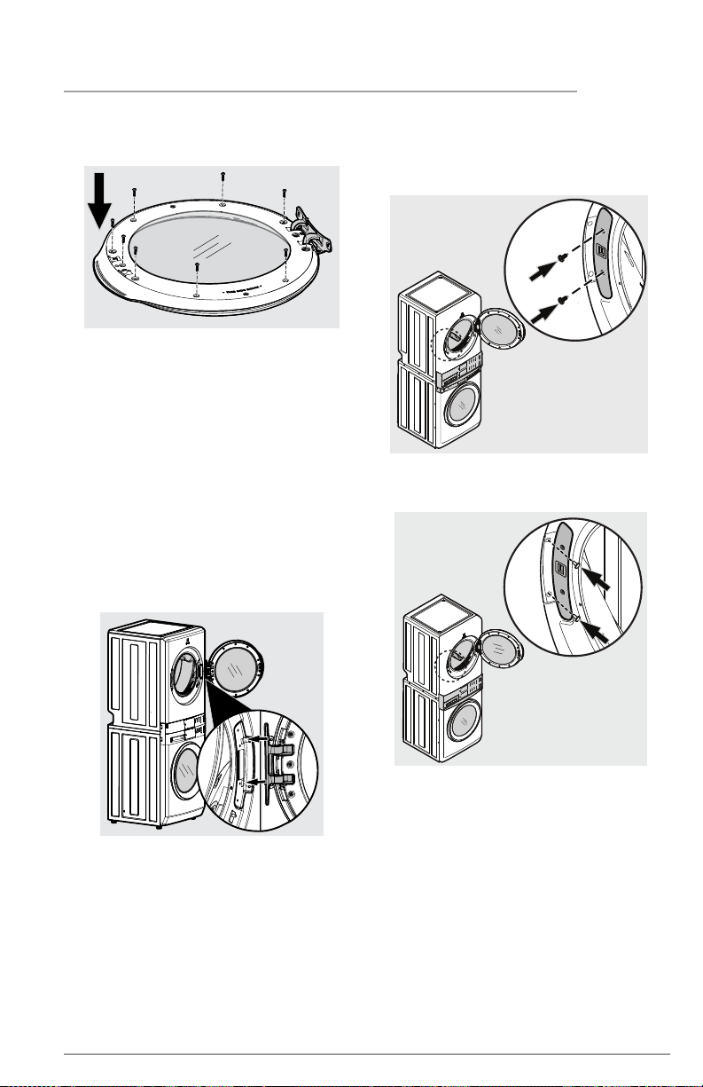
INSTALLATION
39
7. Reinstall all eight screws using a #2
square bit driver.
8. Verify the gasket has not separated
from the metal ring. Go back to step 5
if the gasket has separated.
9. Reinstall the striker and previously
removed screws.
10. Reinstall the hinge cover.
Reinstalling door Assembly
1. Rotate the door and hang the upper
hook on the back of the hinge in the
upper hole of the front panel.
Reinstalling Latch and Hole Plugs
1. Install the door latch using the
previously removed screws.
2. Reinsert the plastic hole plugs.
2. Reinstall and tighten all four screws
removed earlier - two front screws first,
then the two side screws.
Verify Reversed Dryer Door
Operation
1. Test the door for freely swinging,
smooth operation and a secure latch
when closed.
2. Plug in the dryer and close the door.
Start a test cycle: the drum should
tumble until the door is pulled open or
the cycle is paused or canceled.
Page 40
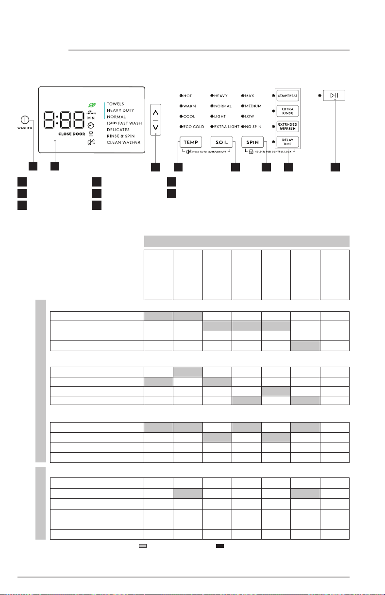
40
WASHER CONTROLS AND SETTINGS
Settings Chart - 7300 series
1
2
1
Power
2
LED Display
3
Cycle Selector
These temperature, spin speeds, soil levels and options are available with the following cycles:
TEMP
HOT
WARM
COOL
ECO COLD
SOIL
HEAVY
NORMAL
LIGHT
EXTRA LIGHT
CYCLE SETTINGSCYCLE OPTIONS
SPIN
MAX
MEDIUM
LOW
NO SPIN
OPTIONS
STAINTREAT
EXTRA RINSE
EXTENDED REFRESH
DELAY TIME
CONTROL LOCK
MUTE/UNMUTE
= Available selections. = Factory presets. = Non-modifiable presets.
This manual covers many models and not all cycles, options, or features listed are available
on every model. Consoles shown above for reference only. Your model may differ.
4
Temperature
5
Soil Level
6
Spin Speed
4 7
7
Cycle options
8
Start/Pause
TOWELS
HEAVY
DUTY
5 83 6
CYCLE SELECTIONS
FAS T
MIN
NORMAL
15
WASH
DELICATES
RINSE &
SPIN
CLEAN
WASHER
Page 41
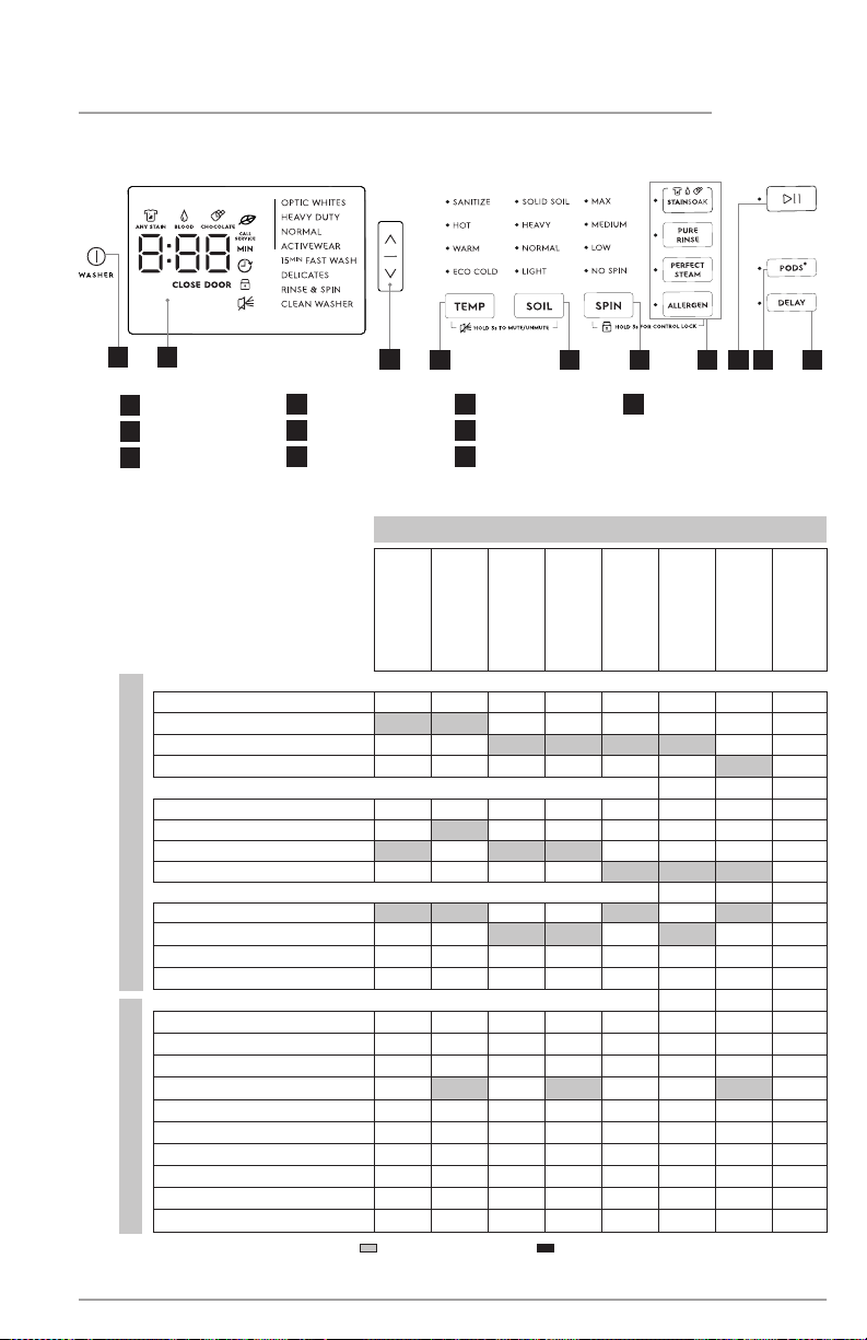
WASHER CONTROLS AND SETTINGS
Settings Chart - 7600 series
1
2
3
4 7
5 8 109
41
6
1
Power
2
LED Display
3
Cycle Selector
These temperature, spin speeds, soil levels and options are available with the following
cycles:
TEMP
SANITIZE
HOT
WARM
ECO COLD
SOIL
SOLID SOIL
HEAVY
NORMAL
LIGHT
SPIN
CYCLE SETTINGSCYCLE OPTIONS
MAX
MEDIUM
LOW
NO SPIN
OPTIONS
STAINSOAK (Any Stain)
STAINSOAK (Blood)
STAINSOAK (Chocolate)
PURE RINSE
PERFECT STEAM
ALLERGEN
DELAY
CONTROL LOCK
MUTE/UNMUTE
PODS®
= Available selections. = Factory presets. = Non-modifiable presets.
PODS® is a registered trademark of Procter & Gamble Company, Cincinnati OH, used under license by Electrolux.
4
Temperature
5
Soil Level
6
Spin Speed
7
Cycle Options
8
Start/Pause
9
PODS®
CYCLE SELECTIONS
OPTIC
WHITES
HEAVY
DUTY
NORMAL
10
Delay
FAS T
MIN
ACTIVEWEAR
15
WASH
DELICATES
RINSE &
SPIN
CLEAN
WASHER
Page 42
42
Cycle Selection
Press the power button to turn on the unit.
Then press the cycle selector in either
direction to scroll to the desired cycle and
the indicator light for the selected cycle
illuminates.
The estimated cycle time will appear on the
LED display and indicator lights adjacent to
the default settings (water temperature, final
spin speed, and soil level) illuminate for the
cycle selected. See
for the default settings for each cycle.
Cycle settings and cycle options can be
changed using the temp, spin and soil
buttons. See
WASHER CONTROLS AND SETTINGS
Options
descriptions of available settings.
For best results
Follow the fabric care
label instructions
on items to be
washed.
Washer Settings Chart
Cycle Settings
and
Cycle
To change the cycle once the cycle has
begun, press power to turn the machine off.
Press power to turn the machine on again
and select a new cycle, then press start/
pause.
Press start/pause to stop the cycle.
• Pressing the cycle selector button
• Selecting the PODS® setting may
• Deselect pure rinse (7600) or extra
for detailed directions and
NOTE
without first powering off and on the
unit will not change the cycle.
increase fast wash time by several
minutes.
rinse (7300) for a spin only cycle. Select
no spin for a drain only cycle.
Cycles
LOAD LOAD TYPE CYCLE DESCRIPTION
OPTIC WHITES White loads • SmartBoost action
HEAVY DUTY Large heavily soiled loads • longer agitation
NORMAL Mixed loads, cotton • moderate agitation
ACTIVEWEAR Highly solid lightweight synthetic
TOWELS Towels • long agitation
FAST WASH
15 min.
DELICATES Small lightly soiled loads (delicate
RINSE & SPIN Rinse and spin only (cold rinse or
CLEAN WASHER See “Care and Cleaning” section of the manual
apparel
Small lightly soiled loads (3-5 pieces) • aggressive cleaning motion
fabrics)
add fabric softener)
• longer agitation
• optimized temperatures
• aggressive cleaning motion
• higher temperatures
• moderate cleaning motion
• most energy efficient
• longer agitation
• mild cleaning motion
• extra rinse
• higher temperatures
• extra rinse
• shorter agitation
• gentle cleaning motion
• lower temperatures
• lower spin speeds
• cold temperature
*All cycles not available on every model. See Settings charts
Page 43
WASHER CONTROLS AND SETTINGS
43
Cycle Settings
Washing Temperature
The appropriate washing temperature
will automatically be indicated for the
cycle selected. To change the preset
temperature, press the temp button to scroll
to the desired setting. Select a wash water
temperature according to fiber content,
colorfastness and soil level.
To protect your fabrics, not all temperatures
are available with every cycle. If a
temperature is not available for the cycle,
it cannot be selected by pressing the temp
button.
The temperature selected for the cycle will
be remembered and recalled each time that
cycle is selected in the future.
All wash water temperatures are automatically
regulated to maximize detergent effectiveness
and improve washing performance. The
water heater setting and its distance from
the washer, water usage in other parts of
the home, and seasonally low ground water
temperature in some geographic areas can
affect water temperature.
sanitize (on select models)
Use the sanitize setting to clean and sanitize
heavily soiled, colorfast fabrics including towels,
bedding, cloth diapers, and children’s clothing.
It is recommended that you set your water
heater to 120°F (49°C) or higher to ensure
proper performance during this cycle. If the
setting is lower or the load is extra large, the
cycle time may be extended.
When used with the heavy duty, towels,
and optic whites cycles, the sanitize setting
will kill 99.9% of bacteria with no carryover
of bacteria between loads. No bleach or
harsh chemicals are needed, but higher
temperatures are required. Please check
fabric care labels to prevent damage.
NOTE
NOTE
If the voltage at your outlet is under 110v,
the internal heater may not adequately
heat the wash water. If the cycle is
interrupted while the water is heating, the
final temperature of the wash water may
be lower and sanitation may be reduced.
The wash water is heated by an internal boost
heater to a maximum of 152°F (67°C) as the
load tumbles. Cold water is added to cool
down the load prior to drain and spin.
As a precaution, the washer door remains
locked when the water temperature reaches
130°F (55°C)
NOTE
If the wash cycle is paused or canceled
while the internal drum temperature is
above 130°F (55°C), the door will remain
locked until it cools. You may manually
perform a rinse & spin cycle to cool the
internal temperature sooner.
allergen (on select models)
Removes dust mites and dander from
household objects. The temperature does
increase on this setting.
NOTE
The heavy duty, optic whites and
towels cycles with the allergen option
selected have been designed to meet the
requirements of the NSF P351 protocol
for allergen reduction efficacy. These
cycles and settings will kill dust mites
and eliminate at least 95% of pet dander.
Since higher temperatures are required,
please check fabric care labels to prevent
damage.
The heavy duty, towels, and optic whites
with sanitize setting cycles have been
designed to meet the requirements of NSF
P172 protocol for sanitization efficacy.
NSF Prot ocol P172
Sanitization Performance of Residentia l
and Commercial, Family-Sized Clothes
Washe rs
NSF Protocol P351
Allergen Reduction Performance
of Residential and Commercial,
Family-Sized Clothes Washers
Page 44
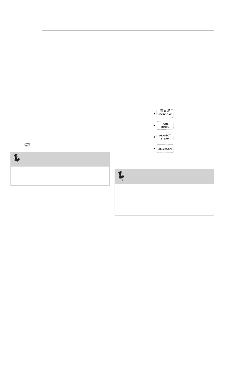
44
WASHER CONTROLS AND SETTINGS
hot
Use this setting for heavily soiled white or
colorfast cottons and blends.
warm
Use this setting for normally soiled white or
colorfast cottons or blends.
cool (on select models)
Some warm water will automatically blend
with cold tap supply to achieve a precise
cold. Use this setting for lightly soiled noncolorfast items, knits, delicates, and hand
washables.
eco cold
Wash and rinse temperatures are equivalent
to temperature of cold tap supply. Use this
selection for fabrics and colors that are
prone to dye transfer. For use with cold
water detergents.
NOTE
The washer will ALWAYS use a small
amount of HOT water to dissolve the pack
when the PODS® option has been selected.
PODS® is a registered trademark of Procter
& Gamble Company, Cincinnati OH, used
under license by Electrolux.
Soil level
Adjust the wash time based on the soil level
of each load. Solid soil (on select models),
heavy, normal, light and extra light (on
some models) soil levels are available.
Spin speed
Max (on select models), high, medium and
low (on some models) spin speeds are
available for each cycle. The spin speed
and/or duration of final spin vary from model
to model and cycle to cycle.
Increasing the spin speed will extract more
water, decrease drying time and conserve
energy. Decreasing the spin speed will
reduce wrinkling.
Select low spin speed (on some models) to
gently spin items that should be line dried.
Use no spin to omit the final spin at the
end of the cycle. The load will be very wet.
Remove items from the wash drum to drip
dry or select a spin only cycle to remove
excess water at a more convenient time. See
Cycle Selection for Spin Only option.
Cycle Options
The default options for each cycle will
automatically be chosen when a cycle is
selected. To protect fabrics, not all options
are available for all cycles. If an option is
not available for a cycle, the indicator will
not light.
Selecting Options
Press an option button to select the desired
options for a wash cycle.
Options vary according to model.
NOTE
If changes to the settings or options are
attempted after the cycle starts, you will
hear several beeps when the buttons are
pressed. To change settings or options,
press start/pause, make the new selections
and press start/pause again.
All settings or options selected for the cycle,
except sanitize (on select models), perfect
steamTM (on select models), allergen (on
select models) and stain treatment options,
will be remembered and recalled each time
that cycle is selected in the future. To return
to factory settings, press and hold soil and
spin buttons at the same time and hold for 3
seconds until the confirmation signal sounds.
To prevent unintentional and accidental
exposure of delicate material to excess heat
or unexpected steam, the sanitize, perfect
TM,
steam
options will need to be reselected each
time.
allergen, and all stain treatment
Page 45
WASHER CONTROLS AND SETTINGS
45
Stain Treatment Options
(on select models)
Your washer is equipped with powerful stain
treatment tools. Depending on your model,
use one of the options below to deal with
tough stains on your garments. See step 5
in the
Operating the Washer
manual for details on adding stain additives
to the dispenser.
StainTreat (7300 series)
Select this option to add a short initial wash
period to available cycles using the stain
treatment additives in the stain soak/treat
compartment. After the stain wash phase,
the load will automatically advance to the
main wash cycle.
StainSoak (7600 series)
Press the Stain Soak button to select the
option, then press the Stain soak button
again to choose one of the following
described stain types. During the wash cycle,
stain treatment and detergent circulate during
the agitating load for approximately 20
minutes. SmartBoost pump technology mixes
the stain treatment and detergent before the
washer advances to the main wash cycle.
• Any Stain
Recirculating wash solution will be
heated by boost heater.
• Blood
Recirculating wash solution will NOT
be heated by boost heater to prevent
setting blood stains.
• Chocolate
Stain wash time is extended with
additional heating by boost heater.
perfect steamTM (on select models)
Select this option to add approximately 20
minutes of tumbling in steam.
section in this
NOTE
• Steam may not necessarily be visible
inside drum during a steam wash cycle.
• Steam may not be present during entire
steam wash cycle.
IMPORTANT
• If steam is selected, rinse temperatures
will be elevated.
• If the wash cycle is paused or canceled
during a steam cycle, the door will
remain locked until it cools. You may
manually perform a rinse & spin cycle
to cool the internal temperature sooner.
• During a steam cycle, steam exiting
from the rear vent of the washer is
normal and not cause for alarm.
Wash Cycle Options
extra rinse (on select models)
Use this option when additional rinsing is
desired to remove excess dirt and detergent. It
is recommended for heavily soiled loads or if
household members have sensitive skin.
pure rinse (on select models)
Use this option to reduce detergent residues
and fragrances that can irritate skin which
rinses cleaner than the extra rinse cycle.
extended refresh (on select models)
Select extended refresh if you will be unable
to remove the load right after the cycle is
complete. The washer recognizes the load
has sat too long and will do a rinse and spin
to keep the load fresh for up to 12 hours.
When you are ready to remove the load
during the extended refresh segment, you
must press power to end the cycle and open
the door.
PODS® (on select models)
Select this option when using a detergent
pack in a model equipped with a PODS®
button (on select dispenser only). This option
will divert the flow of water to the detergent
pack compartment optimizing the detergent
pack performance.
PODS® is a registered trademark of Procter
& Gamble Company, Cincinnati OH, used
under license by Electrolux.
Page 46
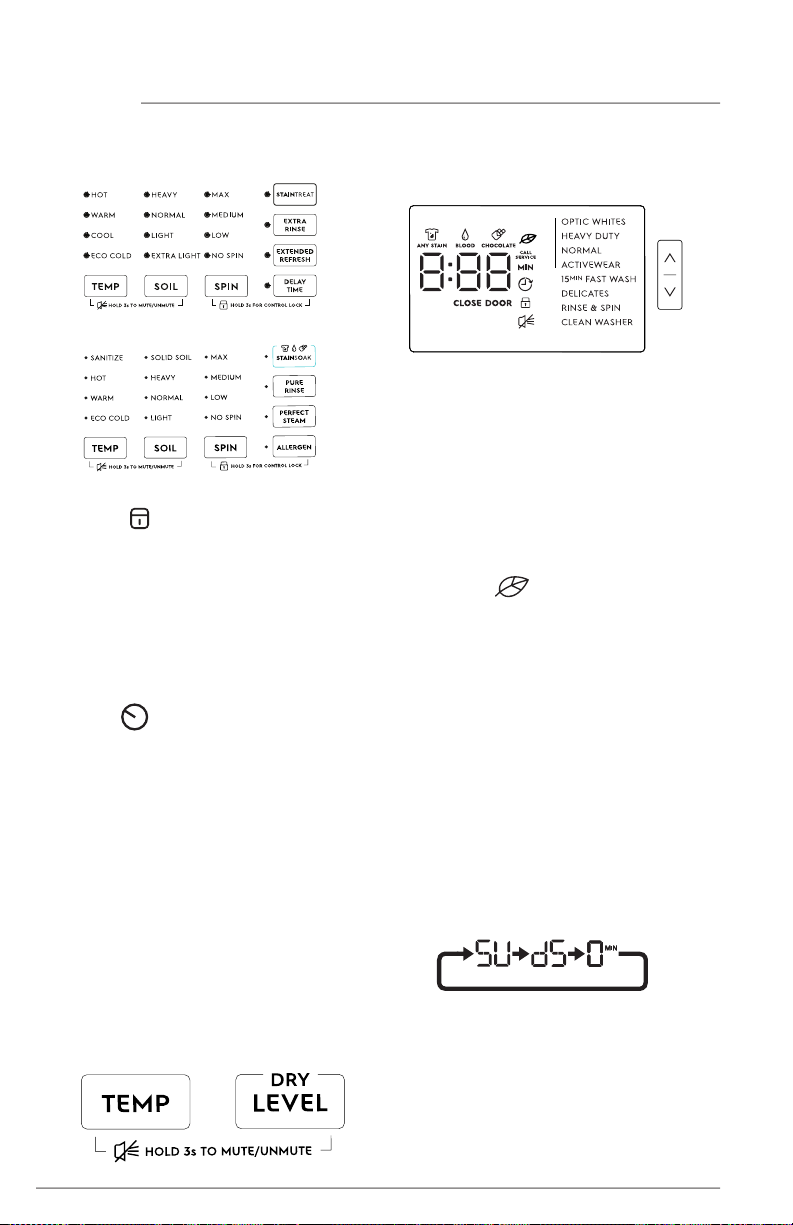
46
WASHER CONTROLS AND SETTINGS
Control options
7300 Series
7600 Series
control lock
To lock or unlock the controls between cycles:
For 7300 Series: Press spin and delay time for
3 seconds.
For 7600 Series: Press spin and allergen.
The control lock icon will show on the LED
display. Use this feature to reduce the likelihood
of accidental operation by children. Washer
cycles will not run when control lock is
activated.
delay time
Use delay or delay time to delay the start
of the washing cycle from 30 minutes to 12
hours. To turn on the delay time option, press
delay or delay time and keep pressing to
scroll through for the desired amount of time
delay and press start. The delay time icon
illuminates on the LED display indicating that
the delay time option is activated. The time
begins counting down on the LED display once
the washer start/pause button is pressed.
Chime
A signal will sound at the end of each cycle
(and periodically during extended refresh) if
option is activated.
To mute or unmute the chime, press and hold
the temp and Soil buttons for 3 sec.
Other Features
LED Display
Icons may vary according to model.
The estimated total cycle time will be
displayed when the cycle is selected. The
time may increase if water pressure is low,
over-sudsing occurs or the load becomes
unbalanced. The approximate time
remaining will be displayed during the cycle.
The eco, control lock, close door, mute
(some models), and delay time will also
appear on this LED display.
Eco indicator
The eco symbol will light up on the LED display
to indicate that the selected combination of
temperature, spin speed and options are eco
friendly.
Oversuds Protection
A situation where over-sudsing has been
detected by the washer will result in the
washer requiring additional rinses until the
suds have been cleared. Each extra rinse
the washer performs to clear the suds will
add approximately 5 minutes to the cycle
duration. The LED will display “SU” followed
by “dS” and then the remaining cycle time (0
min) for 60 seconds and then repeat. Press
cancel to turn off the alert message. The
washer will continue to perform rinse cycles
until suds are dissolved.
(60 sec loop)
Page 47
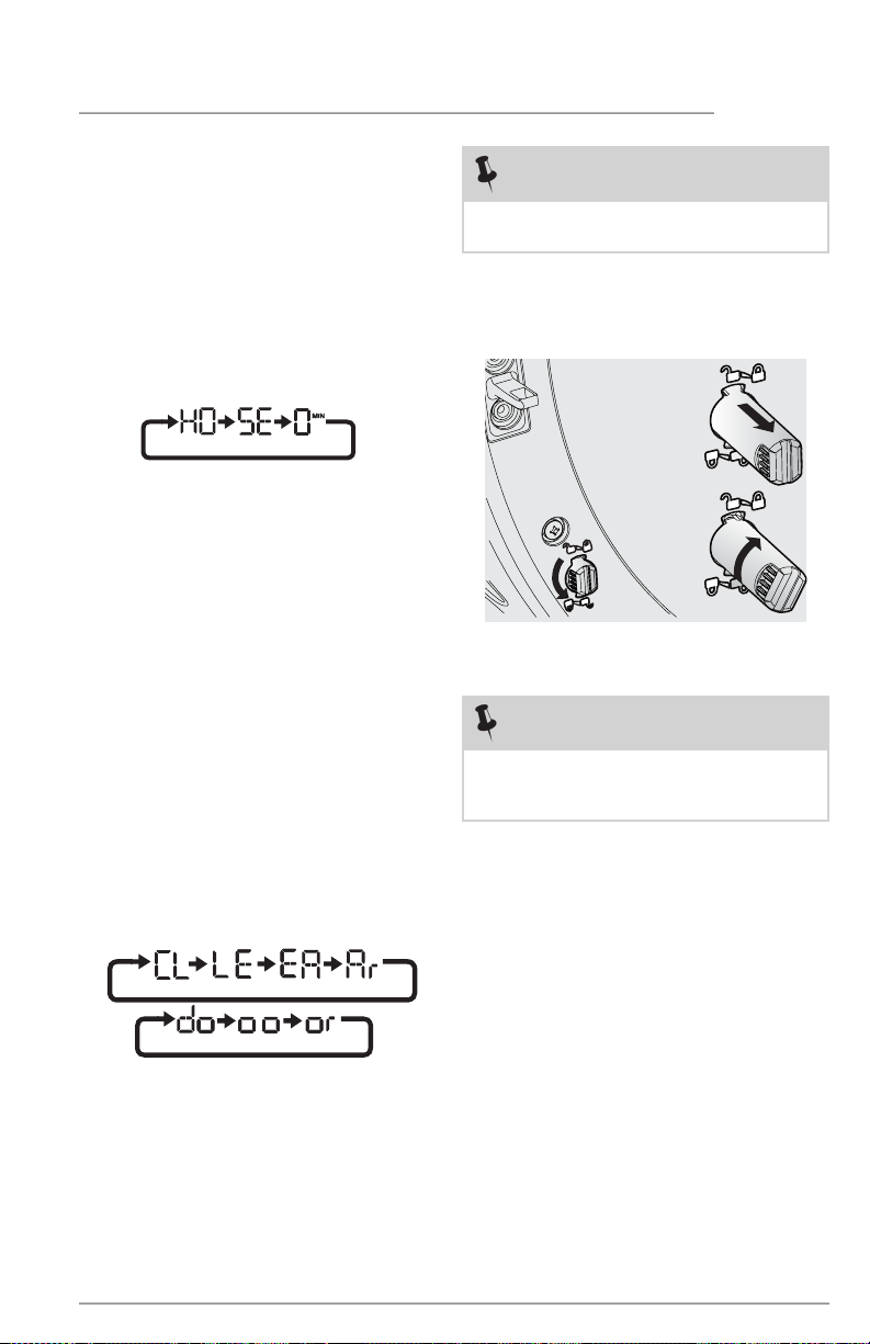
WASHER CONTROLS AND SETTINGS
47
Reversed Hose Detection
If condition is detected where the inlet
hoses have been installed incorrectly (hot
supply to cold inlet and cold supply to hot
inlet), the washer will alert you. The LED will
display “HO” followed by “SE” and then the
remaining cycle time (0 min) for 60 seconds
and then repeat. Acknowledge the reversed
hose condition by pressing the cancel
button. Shut off each water supply valve and
attach each supply hose to the correct inlet
connection on the washer.
(60 sec loop)
Drum Light (on select models)
The drum light will come on whenever
the door is opened to illuminate the drum
during loading and unloading. Closing the
door turns off the light. The drum light will
automatically turn off if the door is left open
more than 3 minutes.
Reversible Door
Your washer may be equipped with a
reversible door. The door can be hinged on
the right or left side.
Trapped Item Detection
If an item is detected to be trapped between
the door and the door gasket, the washer
will pause the cycle and play an alert chime.
The LED will display a loop of “CLEAr door”
as shown below until the cancel button is
pressed. Press the cancel button to unlock
the door and remove the trapped item, then
close the door and restart the cycle.
NOTE
If unable to rotate the stand by hand, a coin
or flat blade screw driver can be used.
The stand is spring loaded and will extend.
Rotate it clockwise to lock in the extended
position.
2
1
To disengage the stand, rotate to unlock, push
the stand in and rotate to lock position.
3
NOTE
If door stand will not turn to locked
position, fully turn it to unlock position and
try to lock again.
(60 sec loop)
(60 sec loop)
Door Stand Ventilation
Help prevent odor buildup and reduce
humidity between washes by utilizing your
washer’s door stand ventilation feature.
Open the door, locate the stand below the
door latch and rotate the stand counterclockwise to unlock it.
Page 48
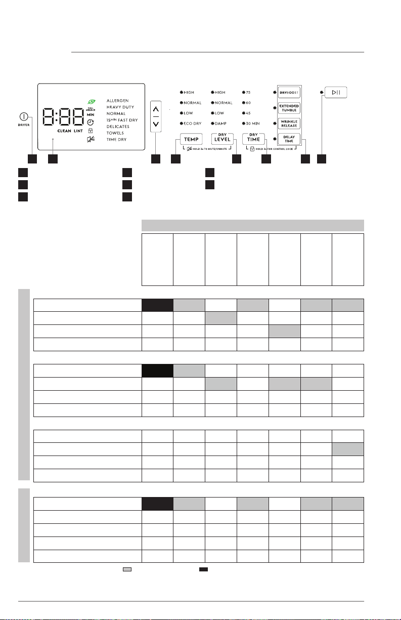
48
DRYER CONTROLS AND SETTINGS
Settings Chart - 7300 series
1 4 72 5 83 6
1
Power
2
Cycle LED Display
3
Cycle Selector
These temperature, dryness levels and options are available with the following cycles:
TEMPERATURE (temp)
HIGH
NORMAL
LOW
ECO DRY
DRYNESS
HIGH
NORMAL
LOW
DAMP
CYCLE SETTINGSCYCLE OPTIONS
Dry Time
75 Min
60 Min
45 Min
30 Min
OPTIONS
DRY BOOST
EXTENDED TUMBLE
WRINKLE RELEASE
DELAY TIME
CONTROL LOCK
= Available selections. = Factory presets. = Non-modifiable presets.
This manual covers many models and not all cycles, options, or features listed are available
on every model. Consoles shown above for reference only. Your model may differ.
4
Temp Selector
5
Dry Level
6
Dry Time
ALLERGEN
7
Options
8
Start/Pause
CYCLE SELECTIONS
FAS T
HEAVY
DUTY
MIN
NORMAL
15
DRY
DELICATES
TOWELS
TIME DRY
Page 49
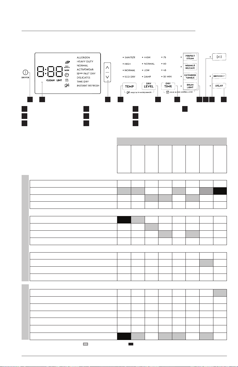
DRYER CONTROLS AND SETTINGS
49
Settings Chart - 7600 series
1 4 72 5 83 6 9 10
1
Power
2
Cycle LED Display
3
Cycle Selector
These temperature, dryness levels and options are available with the following cycles:
TEMPERATURE (temp)
SANITIZE
HIGH
NORMAL
ECO DRY
DRYNESS
HIGH
NORMAL
LOW
DAMP
CYCLE SETTINGSCYCLE OPTIONS
DRY TIME
75 Min
60 Min
45 Min
30 Min
OPTIONS
PERFECT STEAM
WRINKLE RELEASE
EXTENDED TUMBLE
DRUM LIGHT
DELAY
CONTROL LOCK
DRY BOOST
= Available selections. = Factory presets. = Non-modifiable presets.
PODS® is a registered trademark of Procter & Gamble Company, Cincinnati OH, used under license by Electrolux.
4
Temp Selector
5
Dry Level
6
Dry Time
7
Options
8
Start/Pause
9
Dry Boost
CYCLE SELECTIONS
ALLERGEN
HEAVY
DUTY
NORMAL
10
Delay
FAST
MIN
ACTIVE
WEAR
15
DRY
DELICATES
TIME DRY
INSTANT
REFRESH
Page 50
50
DRYER CONTROLS AND SETTINGS
Cycle Selection
Selecting the right cycle to save energy
This dryer has been specifically designed with options to help you save energy and at the
same time utilize the optimal drying setting for your clothing.
The energy efficiency rating is based on the Normal Cycle using the Normal temperature
setting and the normal dryness level.
Some cycles save more energy than others. Cycles that use the least amount of heat save
the most energy and display the leaf icon on the console. Use the lowest heat setting
(auto and timed dry cycles) and less dry setting (auto dry cycles) to save on energy and
prevent over drying your clothing.
Press the power button to turn on the unit.
Turn the cycle selector in either direction
or repeatedly press the cycles button
(depending on your model) to scroll to the
desired cycle. The indicator light for the cycle
selected will be illuminated and the estimated
drying time for Auto Dry cycles or the actual
drying time for Time Dry cycles will be
displayed on the LED display screen.
Default settings and options will automatically
be indicated for the cycle selected. In most
cases cycle settings and options can be
changed. See
and
Setting Charts
To change the cycle once it has begun,
press the cancel button before selecting a
new cycle. Turning the cycle selector ring
or pressing the cycles button WILL NOT
change the cycle.
Cycle Settings, Cycle Options,
for more details.
Auto dry cycles
Auto dry cycles take the guesswork out of
selecting the correct drying time for each
load. Moisture sensors sense the moisture
level of the load as it tumbles through the
heated air. With auto dry cycles, the load
will automatically be dried at the selected
temperature to the desired dryness level.
Auto dry cycles save time and energy and
protect fabrics. When the load has reached
the selected dryness level, it will continue to
tumble, unheated, during a cool down period.
This helps reduce wrinkling and makes items
easier to handle during unloading.
sensors may not detect enough moisture to
continue the cycle and the cycle may end
after a few minutes. If this occurs, then select
the time dry cycle to dry such loads.
Room temperature and humidity, type of
installation and electrical voltage or gas
pressure can also affect drying time.
NOTE
Models equipped with the Predictive Dry
feature use the first 90 seconds of Auto
Dry cycles to sense the load in the dryer.
During this 90 second period the LED
display will show 3 circling lines. When the
sensing is complete, the LED display will
show the remaining cycle time in minutes
and accurately count down to the end of the
cycle.
Timed dry cycles
The timed drying cycles allow the selection
of exact drying times. The time dry cycle
allows the option to select drying time
settings ranging from 30 to 75 minutes
(depending on the model). Various drying
times and temperature settings can be
selected when using this cycle.
The fast dry cycles have preset times of 15
minutes with a preset temperature of high.
Dryness levels will not be an available option
when using either of the timed drying cycles.
NOTE
Initial cycle times for auto dry cycles are
only estimates, the actual drying time may
differ slightly from the time displayed.
Drying times vary depending on size and
dampness of the load and fabric type. If the
load is too small or almost dry, the moisture
WARNING
FIRE HAZARD
To avoid fire hazard, DO NOT use heat
to dry items containing feathers or down,
foam rubber, plastics similarly textured,
rubber-like materials. Use the time dry
cycle and the eco dry (no heat) setting.
Page 51
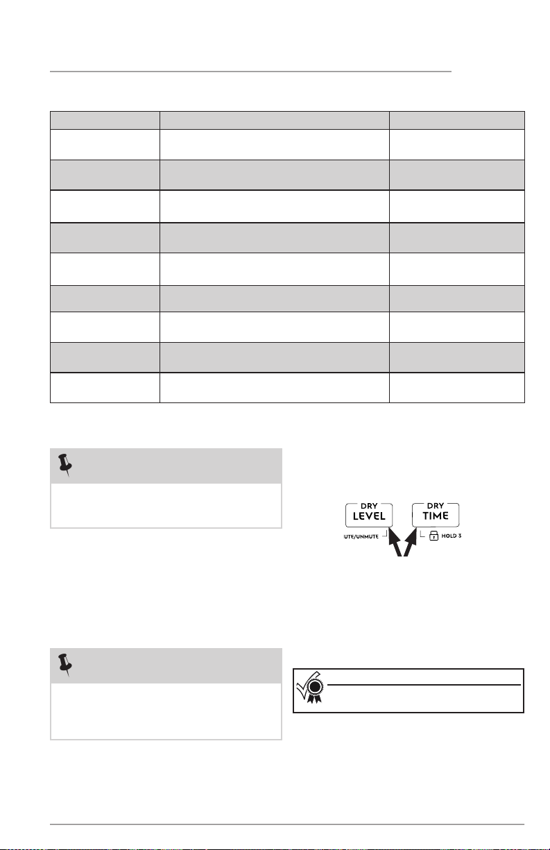
DRYER CONTROLS AND SETTINGS
51
Cycles
LOAD LOAD TYPE CYCLE PRESET
ALLERGEN Allergen removal
HEAVY DUTY Large loads and durable fabrics
NORMAL Everyday loads
ACTIVEWEAR
(select models)
TOWELS
(select models)
15 min. FAST DRY Small loads of 3 to 5 garments • high temperature
DELICATES Knit fabrics and delicates • low temperature
TIME DRY Manually set drying time, heat and dry level
INSTANT REFRESH
(select models)
* Settings can not be changed from preset on select models. See Cycle selections charts for
details.
NOTE
It is not recommended to use fabric softener
sheets with steam cycles or steam options
as it may cause staining on clothes.
(not for items prone to heat damage)
(such as towels, jeans and overalls)
(cottons, linens and sheets)
Lightweight synthetic athletic apparel
(synthetic athletic fabrics and stretch fabrics)
Large loads and durable fabrics
(such as towels, jeans and overalls)
for any type of load
Refresh fabrics, remove odors and reduce
static by injecting steam into clothing.
With exception of the perfect steamtm,
adjustments made to cycle settings and
options will be remembered and recalled
each time that cycle is selected in the future.
• high temperature*
• high dryness*
• high temperature
• high/normal dryness
• normal temperature
• normal/low dryness
• eco dry temperature
• low dryness
• high temperature
• normal dryness
• normal dryness
• normal temperature
• 30-75 minutes time
• high temperature*
• perfect steam™
Cycle Settings
To set or change the drying temperature,
dryness level, or drying time press the temp,
dryness or time dry buttons to scroll to the
desired settings. The indicator light for each
setting will be illuminated when selected.
NOTE
To change a cycle setting once the cycle
has begun, press the start/pause button,
make the new selection and press start/
pause again.
To protect your fabrics, not all temperatures
or dryness levels are available with every
cycle. If a temperature or dryness level is
not appropriate for the cycle, it cannot be
selected and will not be lit when scrolling
through the settings.
Press the dry level and dry time buttons at
the same time until a tone sounds to return to
factory settings.
Drying Temperature (temp)
To change the temperature, press the temp
button to scroll to the desired setting.
For best results
Follow the fabric care label
instructions on items to be dried.
sanitize (on select models)
Recommended for durable fabrics and towels.
Use this selection to remove harmful bacteria
from your clothing or other items where
sanitization is desired. This option will kill
99.9% of bacteria using a higher temperature
required to kill bacteria. Please check fabric
care labels to prevent damage.
Page 52
52
DRYER CONTROLS AND SETTINGS
high
Recommended for most cotton fabrics.
normal
Recommended for wrinkle free, easy care,
lightweight fabrics and bulky loads.
low (on select models)
Recommended for delicate fabrics.
eco dry (no heat)
This setting should only be used with a time
dry cycle to dry items containing feathers,
down, foam rubber, plastics or rubber-like
materials; to refresh clothing, stuffed animal,
pillows or blankets; and to dust draperies.
Dryness level (dry level)
To set or change the dryness level, press
the dry level button to scroll to the desired
setting.
The dryness levels include high, normal, low,
and damp.
Occasionally a load may seem too damp
or over-dried at the end of the cycle. Select
high to increase drying time for similar
loads in the future. Select low to decrease
drying time for similar loads.
Select damp for items you wish to partially
dry before hanging or ironing.
Drying time (dry time)
Manually select or change the drying time
for a time dry cycle (on select models) by
pressing the dry time button to scroll though
the available options. Time dry options
include 30, 45, 60 and 75 minutes (dependent
on model).
All actual or predicted dry times will count
down on the LED display.
Cycle options
Chose desired options. See Cycle Selection
Chart.
NOTE
To change a cycle option once the cycle
has begun, press the start/pause button,
make the new selection and press start/
pause again.
To protect your fabrics, not all options are
available with every cycle. If an option is not
available for a cycle, the indicator will not light.
perfect steamTM (on select models) The
perfect steam
the clothing prior to cool down to reduce
wrinkling, ironing and static cling.
TM
option injects steam into
NOTE
It is not recommended to use fabric softener
sheets with steam cycles or steam options
as it may cause staining on clothes.
dry boost
This option increases the drying
effectiveness for heavier fabrics or bulky
loads by increasing the drying temperature
by less than 20°F (>1°C). (Varies based on
cycle selection).
leaf icon
This icon will appear on the console when
the dryer is using energy efficient settings.
These settings use less heat and longer
cycle times to dry. The dryer will always
default to the energy efficient Normal cycle
with the leaf icon displayed.
wrinkle release
The wrinkle release option helps prevent
wrinkles and tangling by tumbling the dry
load without heat for 5 minutes out of every
10 minutes. The 5 minutes on and 5 minutes
off is repeated for a total 45 minutes. A chime
will sound after each tumble as a reminder to
remove the dried load.
NOTE
When extended tumble and wrinkle
release options are both selected the
amount of time the load will tumble
without heat will increase to a period of
up to 75 minutes.
extended tumble
Select the extended tumble option if the
dried load might not be removed promptly
at the end of the cycle. The dried load will
tumble continuously without heat for 30
minutes. A chime will sound periodically to
remind you to remove the dried load.
delay time
Use delay time/delay to delay the start of
the drying cycle to a time convenient to your
schedule or during off-peak energy hours.
The start of any cycle can be delayed for
Page 53
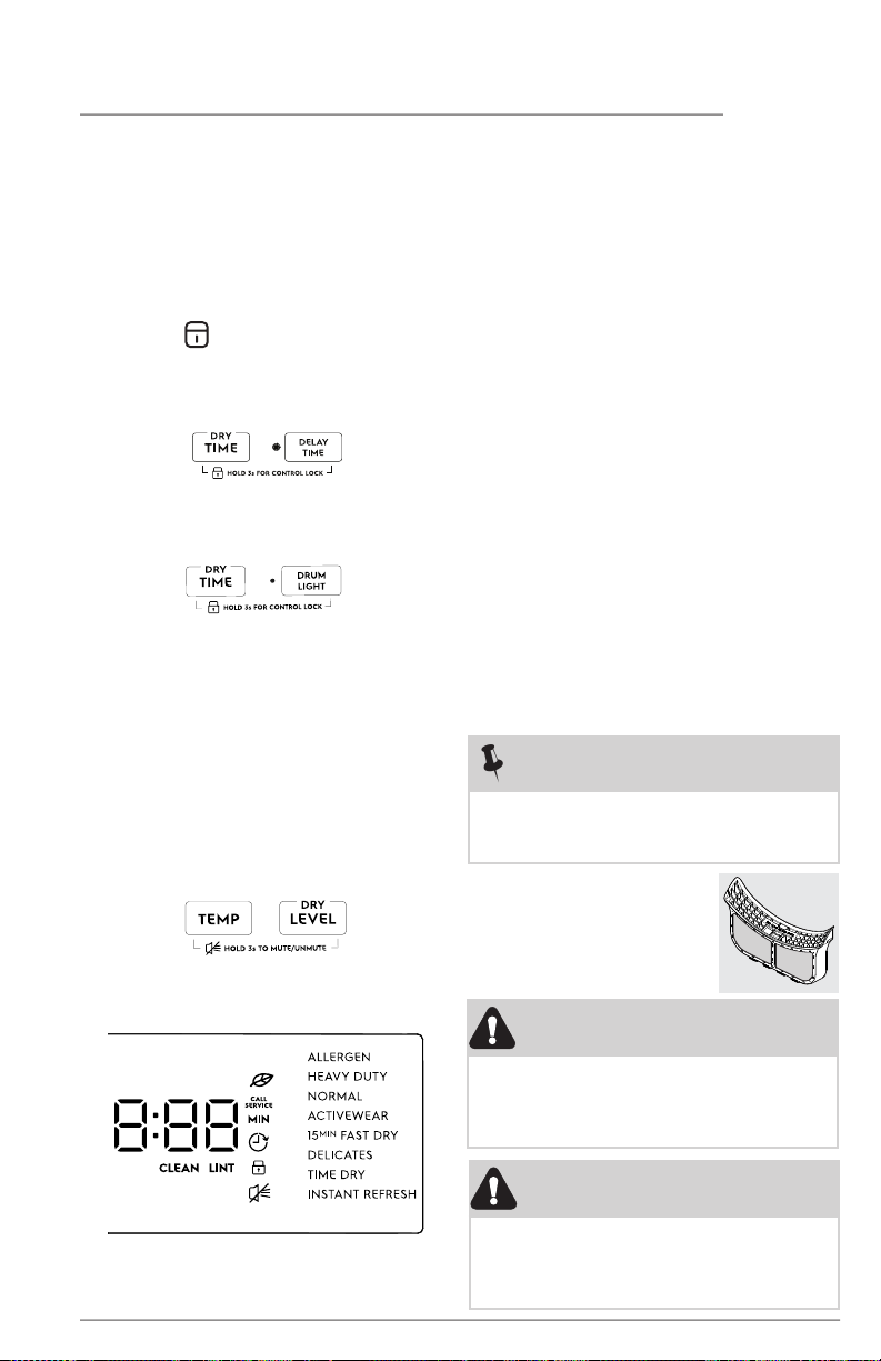
DRYER CONTROLS AND SETTINGS
53
30 minutes to 12 hours. After selecting the
delay time option, use the cycle button. Press
delay or delay time and keep pressing to scroll
to the desired delay time and press start. The
delay time icon will illuminate on the LED
display to indicate the delay time option is
activated, The delay time will begin counting
down on the LED display once activated.
control lock
To lock or unlock the controls between cycles
on the 7300 series, hold the dry time and
delay time buttons for 3 seconds.
To lock or unlock the controls between cycles
on the 7600 series, hold the dry time and drum
light buttons for 3 seconds.
The control lock icon will show on the LED
display. To unlock the controls scroll to the
control lock option again and press select.
Use this feature to reduce the likelihood of
accidental operation by children. Dryer cycles
will not run when Control Lock is activated.
chime
A signal will sound at the end of the cycle
(and periodically during extended tumble
or wrinkle release). To mute or unmute the
chime, press and hold the Temp and Dry
Level button for 3 seconds.
Other Features
LED display
will be displayed when the cycle is selected.
Once the cycle has started, the estimated
remaining time will be displayed for the
remainder of the cycle.
Models equipped with the Predictive Dry
feature use the first 90 seconds of Auto Dry
cycles to sense the load in the dryer. During
this 90 second period the LED display shows
2 circling lines. When the sensing is complete,
the LED display shows the remaining cycle
time in minutes and accurately count down to
the end of the cycle.
Delay time, leaf, control lock, mute icons
(select models) and CLEAN LINT will also
appear on this LED display when activated.
Drum light (on select models)
The drum light will come on whenever
the door is opened to illuminate the drum
during loading and unloading. Closing the
door turns off the light. The drum light will
automatically turn off if the door is left open
more than 3 minutes. Select the drum light
option to enable or disable the drum light.
Reversible door
The dryer is equipped with a reversible
door. The door can be hinged on the right
or left side.
NOTE
For step-by-step instructions on door
reversal, refer to the Installation sections
of this guide.
LuxCareTM Lint Shield filter
The dryer is equipped with
a clamshell style LuxCareTM
Lint Shield filter.
WARNING
Icons may vary according to model.
The estimated cycle time, the actual time
for time dry, or the delay time countdown
Clean the filter after every load. A CLEAN
LINT message will appear when the unit is
powered on as a reminder to clean the lint
filter before starting a cycle.
WARNING
Clean the filter after every load. A CLEAN
LINT message will appear when the unit is
powered on as a reminder to clean the lint
filter before starting a cycle.
Page 54
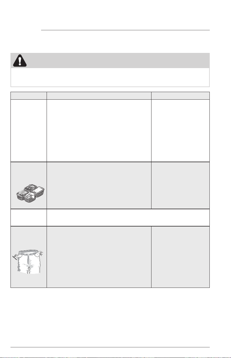
54
WASHER OPERATING INSTRUCTIONS
Operating the Washer
CAUTION
DO NOT leave the door open if there are small children or pets present. An open door
could entice children to hang on the door or crawl inside the washer.
STEPS
1. Sort
laundry
into loads
that can
be washed
together.
2. Prepare
items for
washing.
3. Pretreat
stains and
heavy soil.
4. Add
laundry
load to
wash tub.
TIPS IMPORTANT
• Sort by recommended cycle and water
temperature.
• Separate white, light, and colorfast items from
dark and non-colorfast items.
• Separate items that shed lint from items
that attract lint. Casual, synthetic, knit, and
corduroy items will pick up lint from towels,
rugs, and bedspreads.
• Separate heavily soiled items from lightly
soiled items.
• Separate lacy, sheer, loosely knit, or delicate
items from durable items.
• Empty pockets.
• Brush off lint and dirt. Shake out rugs and
beach towels.
• Close zippers, fasten hooks, button buttons,
and tie strings/sashes. Remove non-washable
trims and ornaments.
• Place delicate and small items (bras, hosiery,
etc.) in a mesh bag (not included).
See stain treatment function in
Stain Removal Guide
• Combine large and small items in a load.
Load large items first.
• Large items should not be more than half the
total wash load.
• Washing single items is inefficient and may
cause an out-of-balance load. Add 1 or 2
similar items to help balance load.
• Wash single heavy items (comforter, sleeping
bag, etc.) separately.
• The washer can be fully loaded, but the
items should not be tightly packed. The door
should close easily.
ENTRAPMENT and TIP-OVER HAZARD
for more information.
Cycle Options
for your particular model or
DO NOT machine
wash items containing
fiberglass. Small particles
of fiberglass left in drum
may transfer to fabrics in
other loads and cause
skin irritation and/or
damage to fabrics.
DO NOT wash water
resistant and water
repellent type clothing or
other materials
Mend rips and tears to
prevent further damage
during washing.
Turn knit items inside out
to prevent pilling.
DO NOT overload the
washer.
DO NOT WASH: Water
resistant and water
repellent clothing or other
materials.
Page 55
WASHER OPERATING INSTRUCTIONS
55
STEPS
5. Add wash
products to
dispenser.
6. Select the
cycle and
settings for the
load.
7. Start the
washer.
8. Remove items
from washer
when cycle
has ended.
TIPS IMPORTANT
• Water conditioners, detergent boosters
and enzyme products may be added
with detergent.
• See
Adding Laundry Products
tailed information on the use of the product dispensers.
• See
Adding Laundry Products
detailed information on the use of
various wash products (detergent,
bleach, stain treatment, fabric softener,
etc).
• See
Cycle Selection, Cycle Settings, and
Cycle Options
of cycle controls.
• See
Cycle Setting Charts
which settings are available for each
cycle.
• To provide the best care, not every setting or option is available with every cycle. If a setting or option is not available
for the cycle selected, the indicator will
not light.
• Close the door and press start/pause.
The washer will not operate with the
door open. “CLOSE DOOR” will be displayed as a reminder to close the door.
• To add a forgotten item to the washer
any time during the wash portion of the
cycle, press start/pause. When the door
unlocks, open the door, add the item,
close the door and press start/pause to
resume cycle.
• To change settings or options after the
cycle has begun, press start/pause,
change the settings, and then press start/
pause. If the cycle is not paused first, the
unit will emit several beeps when the buttons are pressed but no changes to the
cycle will be applied.
• To change the cycle once the cycle has
begun, press cancel to cancel the cycle,
select the new cycle, and press start/
pause to begin the new cycle. Changing
a cycle selection without canceling the
current WILL NOT change the cycle.
• To cancel a cycle, press cancel.
• A signal will sound at the end of the cycle if the chime option is not set to mute.
• Remove items when the cycle ends and
place in dryer, line dry or dry flat as
directed on the fabric care label.
for detailed descriptions
for de-
for
to determine
Follow manufacturer’s
instructions and
recommendations when
using wash products.
Open and close the
dispenser drawer slowly.
Closing the drawer too
quickly could result in early
dispensing of the bleach or
fabric softener.
Follow fabric care label
instructions on items to
be washed.
Make sure that the PODS®
option is selected when
using models that have a
separate detergent pack
compartment. See Adding
Laundry Detergent to the
Adaptive Dispenser™
DO NOT force door open.
As a safety measure, the
door will automatically lock
during the entire wash cycle.
Pause or cancel the wash
load to unlock the door.
If the cycle is interrupted
during spin, the door lock
will not release until the tub
has stopped spinning.
If the water level is above
the bottom of the door
opening/flexible door gasket, the lock will not release.
Excess wrinkling, color transfer
or odors may develop in items
left in the washer after the
cycle has ended.
PODS® is a registered trademark of Procter & Gamble Company, Cincinnati OH, used
under license by Electrolux.
Page 56
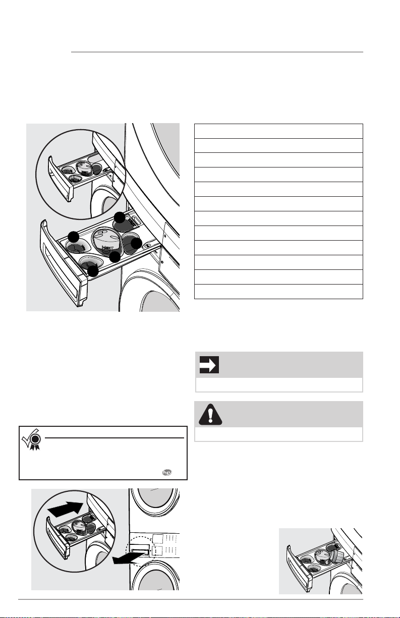
56
WASHER OPERATING INSTRUCTIONS
Adding Laundry Products
Laundry product dispensers
Product dispenser - Adaptive Dispenser™
7300 Series
1. Liquid Fabric Softener
2. Liquid bleach
3. No Pods compartment on 7300 series
4. Stain Treat
5. Liquid or Powder Detergent
3
2
4
5
1
7600 Series
1. Liquid Fabric Softener
2. Liquid bleach
3. Detergent pack compartment*
4. Stain Soak
5. Liquid or Powder Detergent
*Max. 2 packs per load
Detergent, stain treatment (on select
models), liquid chlorine bleach and liquid
fabric softener will be dispensed at the
proper times in the cycle.
Use the cap or scoop provided by the
detergent manufacturer to measure the
amount recommended. Detergent dosage
may need to be adjusted for water
temperature, water hardness, load size and
soil level.
For best results
Use a low-sudsing, high efficiency
detergent to prevent over-sudsing in
front load washers. Look for this
symbol on the detergent label:
Adding Laundry Detergent to the
Adaptive Dispenser™
IMPORTANT
DO NOT mix liquids and powders.
CAUTION
Keep detergent packs away from children.
Liquid detergent
• Use the cap or scoop provided by
the detergent to add recommended
amount of detergent to the detergent
compartment. Pour directly into the
detergent cup, not over the blue cover.
• Amount of detergent may need to
be adjusted
for water
temperature,
water hardness,
and load
size. Follow
manufacturers
instructions.
Page 57
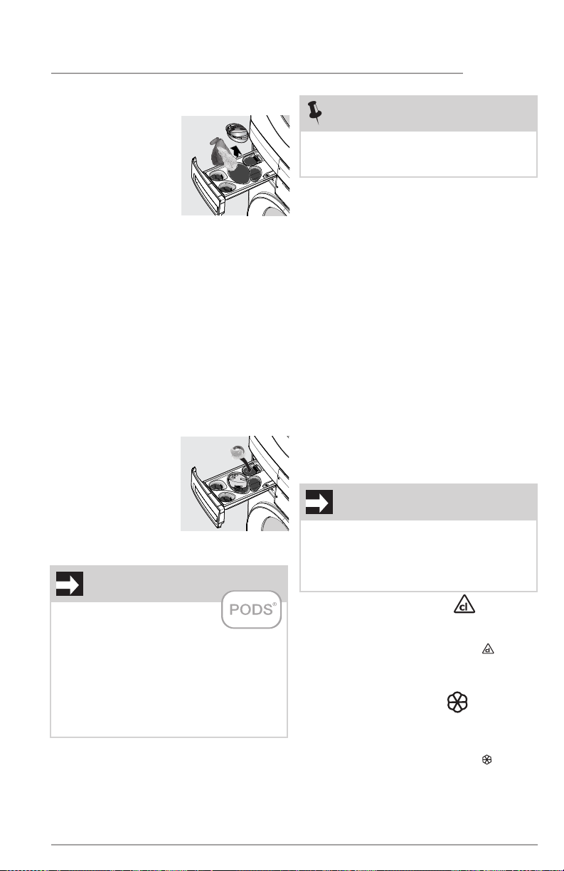
WASHER OPERATING INSTRUCTIONS
57
Powder Detergent
• Remove the liquid
detergent cup and
blue cover before
adding powder
detergent.
• Add powder
detergent directly
to the powder
detergent compartment.
Detergent pack
For 7300 series models
Add detergent pack directly to the empty
drum BEFORE placing laundry into the unit.
DO NOT
directly into the detergent drawer. The
gel coating may cause the detergent
drawer to become clogged.
For 7600 series models
Add the recommended quantity of high
efficiency detergent packs to the detergent
pack compartment in the dispenser.
• DO NOT place
more than two
packs into the
dispenser.
• When using
the fast wash
cycle, only one
detergent pack
should be used.
place detergent packs
IMPORTANT
• When using the detergent
pack compartment, make
sure to select the PODS® option before
starting the load.
• Once the PODS® option has been
chosen, the washer will retain the PODS®
setting until manually changed.
• The washer will ALWAYS use a small
amount of HOT water to dissolve the pack
when the PODS® option has been selected.
PODS® is a registered trademark of Procter
& Gamble Company, Cincinnati OH, used
under license by Electrolux.
NOTE
From time to time you may see water in
the dispenser. This is part of the normal
operation of the washer.
Adding other wash products
• Color-safe bleach, water conditioner,
detergent booster and enzyme
products may be added with detergent.
• Put liquid products in the Main Wash
- liquid detergent compartment or
powder products in the Main Wash -
powder detergent compartment.
Stain Treatment (on select models)
• For heavily soiled or stained loads,
select the Stain option (on select models
only - StainTreat, or StainSoak) and add
the recommended amount of detergent
or stain treatment to stain soak/treat
compartment (on select models).
• See
• See
Cycle Options
Stain options for your model.
Stain Removal Guide
instruction for additional suggestions.
for information about
in this
IMPORTANT
Use of multi-product (detergent plus
softener) sheets or color-absorbing sheets
NOT recommended. They could disable
your machine and result in unwarranted
repair costs.
Liquid chlorine bleach
• If desired, add liquid chlorine bleach to
the compartment labeled Liquid Bleach
and marked with this symbol: .
DO NOT fill above the MAX fill line.
• Add color-safe bleach with detergent.
Liquid fabric softener
• If desired, pour the recommended
amount of liquid fabric softener into the
compartment labeled
and marked with this symbol: .
DO NOT fill above the MAX fill line.
• Use of a fabric softener-dispensing ball is
not recommended in front load washers.
Fabric Softener
Page 58
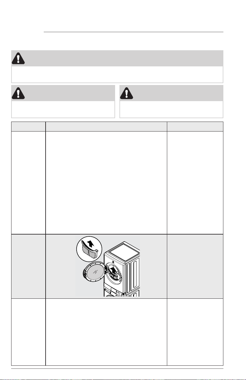
58
DRYER OPERATING INSTRUCTIONS
Operating the Dryer
WARNING
To reduce the risk of fire, electric shock or injury to persons, read the Important Safety
Information in this Use & Care Manual before operating your dryer.
WARNING
DO NOT operate dryer without lint filter in
place.
STEPS
1. Prepare
load for
drying.
2. Check
that the
lint filter is
clean and
in place.
TIPS IMPORTANT
• Dry items of similar fabric, weight and
construction in the same load.
• Separate dark items from light-colored items.
Separate items that shed lint from those that
attract lint.
• Check for stains which may not have been
removed in washing. Repeat stain removal
process and wash again before drying. Dryer
heat may permanently set some stains.
• Place delicate, rubber coated, or small items
in a mesh bag (not included).
• Be sure buckles, buttons and trim are
heatproof and won’t damage the drum
finish. Close zippers; fasten hooks and loop
fasteners. Tie strings and sashes to prevent
snagging and tangling.
WARNING
Clean the lint filter after every load.
DO NOT machine
wash items containing
fiberglass. Small
particles of fiberglass
left in drum may
transfer to fabrics in
other loads and cause
skin irritation and/or
damage to fabrics.
DO NOT wash water
resistant and water
repellent type clothing
or other materials.
DO NOT operate
dryer without lint filter
in place.
3. Load the
dryer and
close the
door.
• Load items loosely. The average wet load will
fill the drum 1/3 to 1/2 full. Items need room to
tumble freely for even drying and less wrinkling.
• If desired, place a dryer fabric softener sheet on
top of the load at the beginning of the cycle.
• When drying large items, dry only two or three
items at a time. Fill out the load with smaller
items.
• For delicate or very small loads, add two
or three similar items to improve tumbling action.
DO NOT overload
the dryer. To save
energy, time and
avoid uneven drying
and wrinkling avoid
overloading the dryer.
DO NOT over-dry.
Over-drying can cause
wrinkles, shrinkage,
lint, and a build up of
static electricity.
Page 59
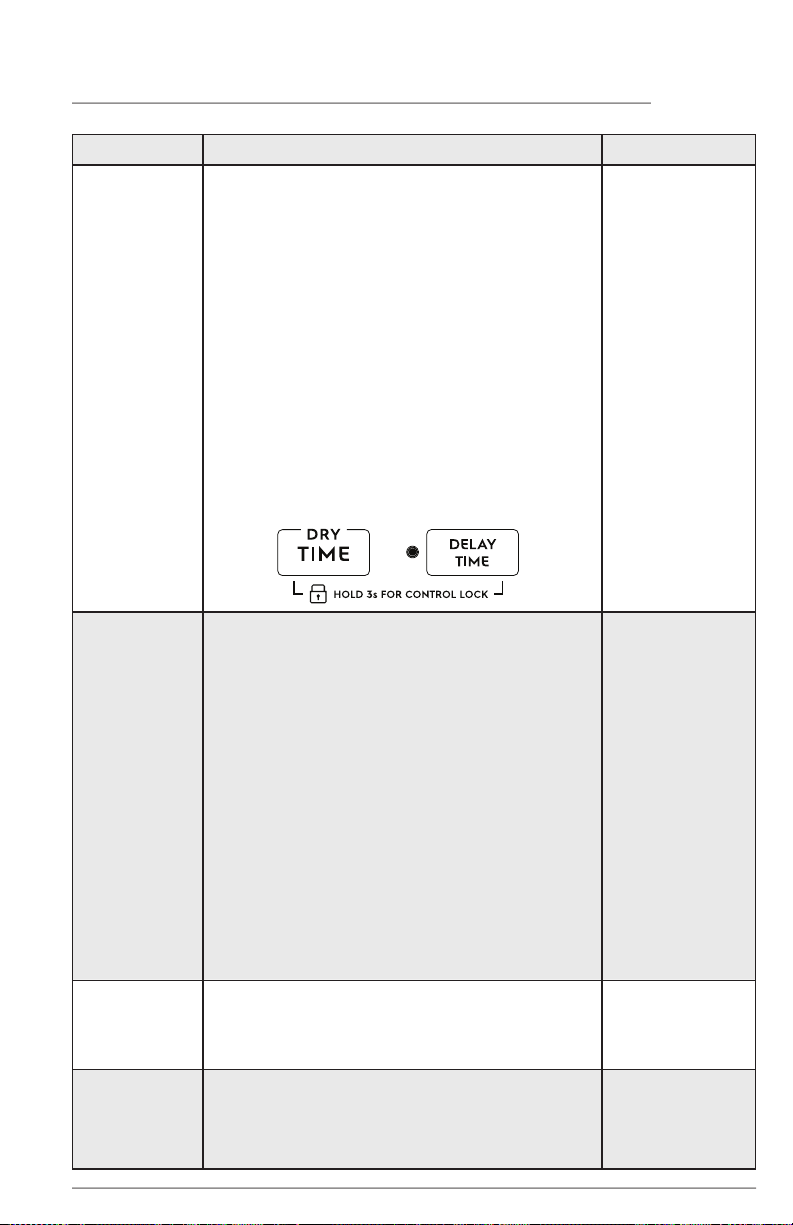
DRYER OPERATING INSTRUCTIONS
59
STEPS
4. Select the
appropriate
cycle and
settings for
each load.
5. Close the
dryer door
and start the
drying cycle.
6. Remove
items when
done.
7. Clean the lint
filter.
TIPS IMPORTANT
• See
• See
• To provide the best care, not every setting
• Adjustments made to most cycle settings will
• To start the drying cycle, close the door and
• To add an item to the dryer drum, press start/
• To change settings or options after the cycle
• To change the cycle once the cycle has begun,
• To cancel a cycle, press cancel.
• A signal will sound at the end of the cycle if the
• Immediately remove items when the cycle is
• See Care and Cleaning section of this
• CLEAN LINT will be displayed at the end of the
Cycle Selection
detailed descriptions of cycle controls.
Cycle Setting Charts
settings are available for each cycle.
or option is available with every cycle. If a
setting or option is not available for the cycle
selected, the indicator will not light. See
Chart
for information of available options for
each cycle by model.
be remembered each time the cycle is selected
in the future. When the dryer is powered on, the
default cycle will be the normal cycle. Select
your desired cycle and previous settings will
remain. To return to factory settings, press the
dry level button and the dry time button at the
same time and hold until the signal sounds. See
Dryer Controls and Settings.
press the start/pause button.
pause. Add the item, close the door and press
start/pause to resume the cycle.
has begun, press start/pause, change the
settings, and then press start/pause. If the cycle
is not paused first, the unit will emit several
beeps when the buttons are pressed but no
changes to the cycle will be applied.
press cancel to cancel the cycle, select the
new cycle, and press start/pause to begin the
new cycle. Changing a cycle selection without
canceling the current WILL NOT change the
cycle.
chime option is not set to mute.
completed and hang or fold.
instruction.
cycle as a reminder to remove lint from filter.
and
Cycle Settings
to determine which
for
Setting
Over-drying can
cause wrinkles,
shrinkage, lint,
harshness, and a
build up of static
electricity.
To prevent
unintentional
and accidental
exposure of
delicate material
to excess heat
or unexpected
steam, the sanitize
temperature
setting and the
perfect steam™
option will not be
remembered and
must be reselected
each time.
The dryer will not
operate with the
door open.
When drying a
single large or
bulky item, such
as a comforter,
pause the cycle
part way through
to turn the item
“inside out” and
maximize drying
effectiveness.
See product
manufacturer’s
instructions.
ALWAYS REMOVE
LINT at the end
of the cycle
(see warning on
previous page).
Page 60
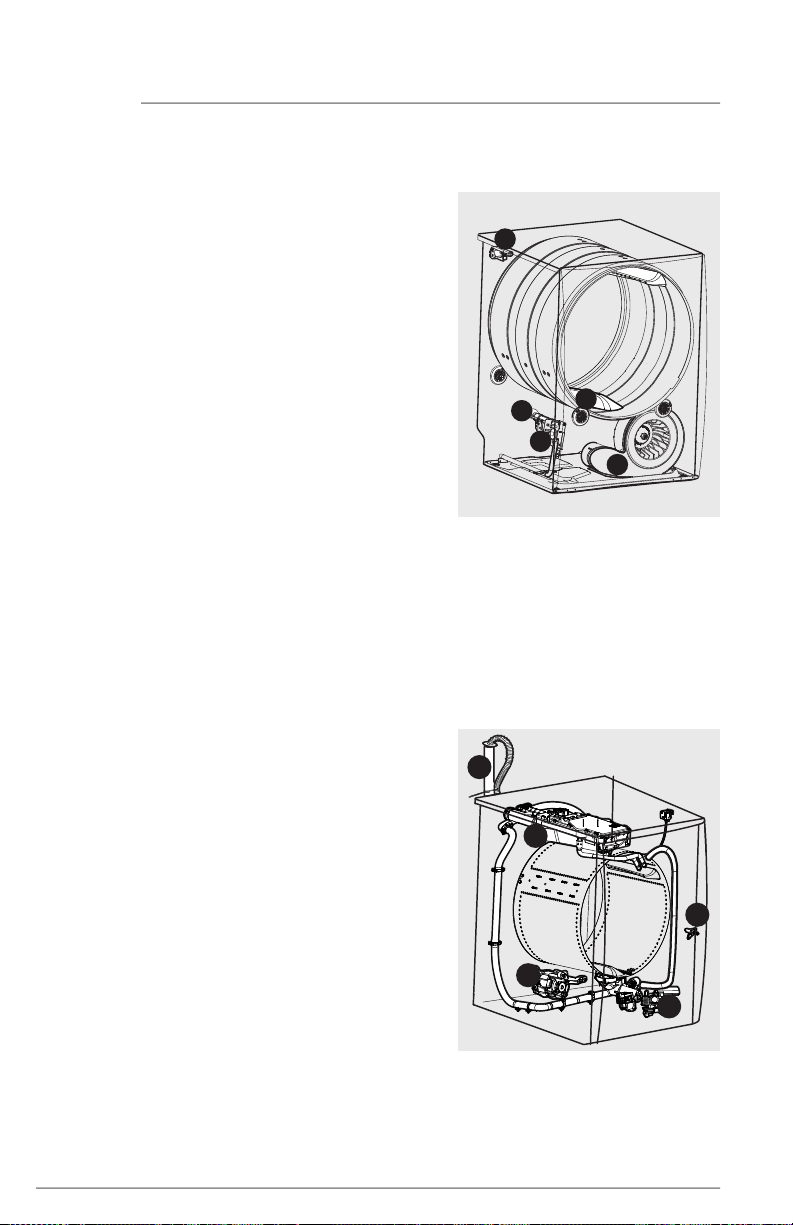
60
NORMAL OPERATING SOUNDS
Dryer
You may or may not hear the following sounds from the laundry center dryer:
A. WATER VALVE (Steam models only.) The flow of
water is controlled by electric solenoids. During
operation there may be a clicking sound as the
valve opens and closes to control the water flow.
B. SUSPENSION ROLLERS The dryer drum is
supported by a set of suspension rollers. At times
there may be a thumping or rolling sound when
the dryer starts. This may happen if the dryer has
not been in use for a period of time, or after a
heavy load has remained in the dryer drum for an
extended period, creating a temporary flat spot on
the edge of the roller. The noise should dissipate as
the dryer operates and the flat spots smooth out.
C. AIR FLOW SYSTEM Your dryer is equipped
with a high volume air handling system. In some
installations there may be some sounds associated
with air movement throughout the dryer, including
the air duct, blower, and exhaust system. This is
normal and can vary with load size and type.
D. GAS VALVE (Gas models only.) The flow of gas is controlled by electric solenoids.
During operation there may be a clicking sound as the valve opens and closes to
control the gas flow.
E. GAS BURNER (Gas models only.) When the burner is operating, there may be sounds
generated as the air flow mixes with the gas flame. This noise is normal and will only
occur when the gas is ignited in the combustion tube.
A
E
B
D
C
Washer
You may or may not hear the following sounds from the laundry center washer:
F. DRAIN HOSE The washer has a flexible drain hose
to carry water from the washer to the stand pipe
of your home. You will hear water flowing into your
stand pipe. This is a normal part of the operation of
the washer.
G. WATER VALVES/DISPENSER As water enters the
dispenser system, it is common to hear a water
flowing sound. This normal sound will vary slightly
based on the water pressure in your home.
H. DOOR LOCK Your washer is equipped with a
door lock with an electric solenoid. There will be
a clicking sound as the washer door is locked or
unlocked.
I. DRAIN/RECIRCULATION PUMPS Your washer is
equipped with multiple high velocity system pumps.
It is normal to hear humming and gurgling sounds
as water is either pumped from the washer during
the drain phase or recirculated during the prewash
and wash phases. Both of these sounds are normal and indicate that your pump is
functioning correctly.
J. HIGH SPEED MOTOR A powerful motor is used to drive the drum to high spin speeds
to extract water from your load. You will hear a sound associated with these higher spin
speeds. This sound is normal and will vary slightly as the spin speed varies with load
size and cycle selected.
F
A
G
J
I
H
Page 61
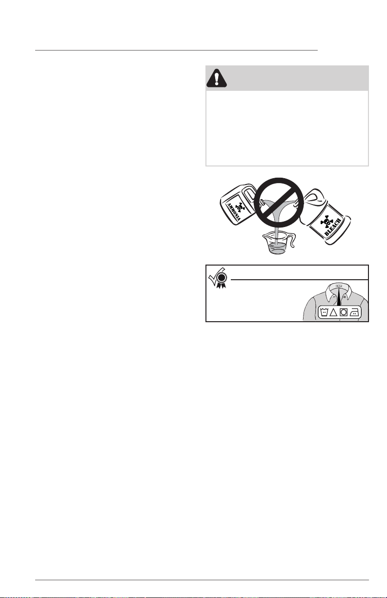
STAIN REMOVAL GUIDE
61
Stain Removal Procedures
To reduce the risk of fire or serious injury to
persons or property, comply with the basic
warnings listed below:
• Read and comply with all instructions
on stain removal products.
• Keep stain removal products in their
original labeled containers and out of
children’s reach.
• Thoroughly wash any utensils used.
DO NOT combine stain removal
products, especially ammonia and
chlorine bleach. Dangerous fumes can
result.
• Never wash items which have been
previously cleaned in, washed in,
soaked in or spotted with gasoline, dry
cleaning solvents or other flammable
or explosive substances because they
give off vapors that could ignite or
explode.
• Never use highly flammable solvents,
such as gasoline, inside the home.
Vapors can explode on contact with
flames or sparks.
For Successful Stain Removal:
• Remove stains promptly.
• Determine the kind of stain, then follow
the recommended treatment in the stain
removal chart on the next page.
• To pretreat stains, use a stain treatment
product, liquid detergent, or a paste
made from powder detergent and
water.
• Use cold water on unknown stains
as hot water can set stains.
• Consult care label instructions for
treatments to avoid on specific fabrics.
• Check for colorfastness by testing stain
remover products on an inside seam.
• Rinse and wash items after stain
removal.
WARNING
HARMFUL VAPOR HAZARD
DO NOT use or mix liquid chlorine bleach
with other household chemicals such
as toilet cleaners, rust removers, acids
such as vinegar, or products containing
ammonia. These mixtures can produce
dangerous fumes which can cause serious
injury or death.
For best results
Follow the fabric care
label instructions on
items to be washed.
Page 62
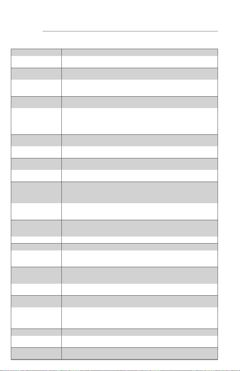
62
STAIN REMOVAL GUIDE
Stain Removal Suggestions
STAIN TREATMENT
Adhesive tape, gum,
rubber cement
Baby formula, dairy
products, egg
Beverages (coffee,
tea, soda, juice,
alcoholic beverages)
Blood Rinse with cold water. Rub with bar soap. Or, pretreat or soak with
Candle wax, crayon Scrape off surface wax. Place stain face down between paper
Chocolate Pretreat or soak in warm water using product containing enzymes.
Collar or cuff soil,
cosmetics
Dye transfer on
white fabric
Grass Pretreat or soak in warm water using product containing enzymes.
Grease, oil, tar (butter,
fats, salad dressing,
cooking oils, car
grease, motor oils)
Ink Some inks may be impossible to remove. Washing may set
Mildew, scorch Wash with chlorine bleach if safe for fabric or soak in oxygen
Mud Brush off dry mud. Pretreat or soak with product containing enzymes.
Mustard, tomato Pretreat with prewash stain remover. Wash using bleach safe for fabric.
Nail polish May be impossible to remove. Place stain face down on paper
Paint, varnish WATER BASED: Rinse fabric in cool water while stain is wet. Wash. Once
Perspiration Use prewash stain remover or rub with bar soap. Rinse. Wash using
Rust, brown or
yellow discoloration
Shoe polish LIQUID: Pretreat with a paste of powder detergent and water.
Tomato Pretreat with prewash stain remover. Wash using fabric safe bleach.
Urine, vomit, mucus,
feces
Wine Pretreat or soak in cold water. Wash in hottest water and bleach
Apply ice. Scrape off excess. Place stain down on paper towels. Saturate
with prewash stain remover or nonflammable dry cleaning fluid.
Use product containing enzymes to pretreat or soak stains. Soak for
30 minutes or more. Wash.
Pretreat stain. Wash using cold water and bleach safe for fabric.
product containing enzymes. Wash using bleach safe for fabric.
towels. Press with warm iron until wax is absorbed. Replace paper
towels frequently. Treat remaining stain with prewash stain remover
or nonflammable dry cleaning fluid. Hand wash to remove solvent.
Wash using bleach safe for fabric.
Wash using bleach safe for fabric.
Pretreat with prewash stain remover or rub with bar soap.
Use packaged color remover. Wash using bleach safe for fabric.
Wash using bleach safe for fabric.
Scrape residue from fabric. Pretreat. Wash using hottest water safe
for fabric. For heavy stains and tar, apply nonflammable dry cleaning
fluid to back of stain. Replace towels under stain frequently. Rinse
thoroughly. Wash using hottest water safe for fabric.
some inks. Use prewash stain remover, denatured alcohol or
nonflammable dry cleaning fluid.
bleach and hot water before washing. Badly mildewed fabrics may
be permanently damaged.
towels. Apply nail polish remover to back of stain. Repeat, replacing
paper towels frequently. DO NOT use on acetate fabrics.
paint is dry, it can’t be removed. OIL BASED AND VARNISH: Use solvent
recommended on label. Rinse thoroughly before washing.
non chlorine bleach in hottest water safe for fabric.
Use rust remover safe for fabric. DO NOT use chlorine bleach
because it may intensify discoloration.
PASTE: Scrape residue from fabric. Pretreat with prewash stain
remover or nonflammable dry cleaning fluid. Rinse. Rub detergent
into dampened area. Wash using bleach safe for fabric.
Pretreat or soak in product containing enzymes. Wash using bleach
safe for fabric.
safe for fabric
Page 63
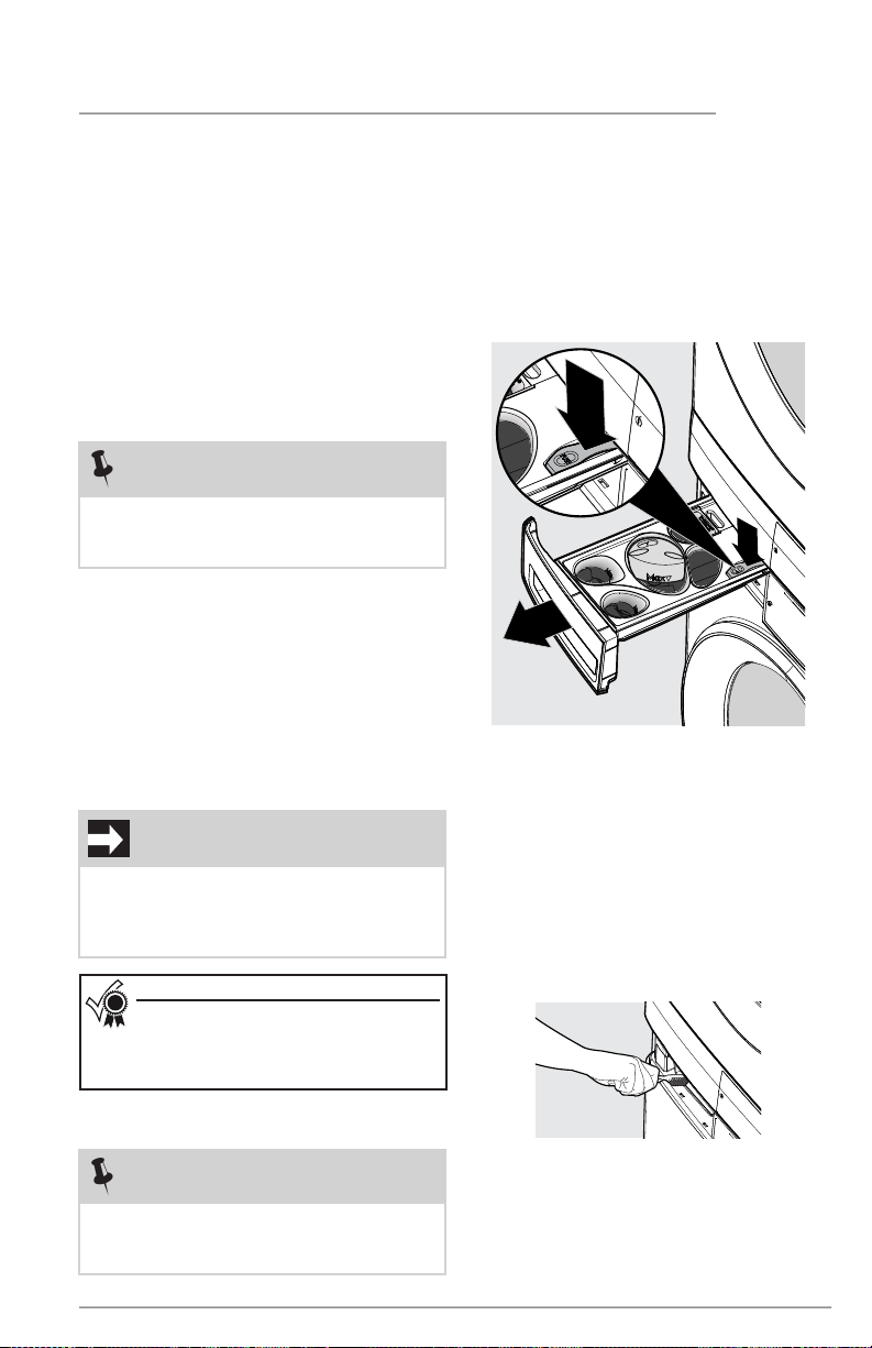
CARE AND CLEANING
63
Inside Routine Cleaning
To help prevent odors or humidity
accumulation leave the door open with
the door stand ventilation feature (on
select models) for a few hours after use or
whenever the washer is not in use.
To Refresh or Clean inside of
Laundry Center
To clean and freshen the laundry center
washer, run the clean washer cycle.
Complete the cycle once a month for best
results.
NOTE
Every 50 cycles, your laundry center will
illuminate the clean cycle indicator to
remind you to run a clean washer cycle.
To begin the cycle, select the clean washer
cycle. Remove the LIQUID DETERGENT cup
from the dispenser if installed. REMOVE ALL
ITEMS FROM WASH DRUM before filling the
detergent compartment with one (1) cup of
liquid chlorine bleach OR one (1) pouch of
TideTM Washing Machine Cleaner. DO NOT
use both. Press start/pause to begin.
Tide is a trademark of The Procter & Gamble Company,
Cincinnati, Ohio.
IMPORTANT
Items left in laundry center washer while
running the clean washer cycle will cause
a severe out-of-balance situation that
could damage the washing machine.
For best results
Immediately follow up with a rinse &
spin cycle. Select max spin with no detergent
or bleach to help clear any residual bleach
left after the clean washer cycle.
Cleaning the compartment dispenser
(7300 series)
To remove:
1. Pull the drawer out until it stops.
2. Press down firmly on the lock tab in the
right rear corner of the dispenser cavity
to release the drawer, then pull out the
drawer to remove.
3. Remove all inserts from the drawers.
4. Rinse the drawer and inserts with
hot tap water to remove traces of
accumulated powders and liquids.
Large amounts of fabric softener
residue may indicate improper dilution
or more frequent cleaning is required.
5. Use a small brush clean the drawer
recess and opening. Remove all
residue from the upper and lower parts
of the recess.
To Clean the dispenser drawer
NOTE
Detergent and fabric softener may build up
in the dispenser drawer. Residue should be
removed once or twice a month.
6. Replace the insert by pressing it in
place until you hear a slight click.
7. Return the dispenser drawer to the
laundry center.
Page 64
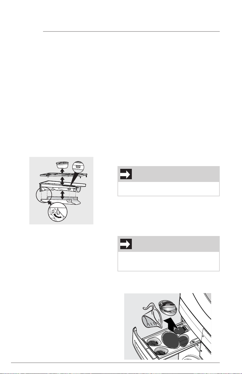
64
CARE AND CLEANING
Cleaning the Adaptive Dispenser™
(7600 Series)
1. Pull the dispenser out until it stops.
2. Press down firmly on the lock tab in the
right rear corner of the dispenser cavity
to release the drawer, then pull out the
drawer to remove.
3. Remove the detergent cup and top
cover from the dispenser drawer.
4. Remove the bottom cover from the
dispenser drawer.
a) First, pull the two lock tabs at the rear
of the dispenser drawer to unlatch the
back cover.
b) Then, gently pull back the two clips on
the front of the bottom cover to fully
release it from the dispenser drawer.
Front
5. Rinse the dispenser drawer, covers, and
detergent cup with hot tap water to
remove traces of accumulated powders
and liquids. Large amounts of fabric
softener residue may indicate improper
dilution or more frequent cleaning is
required.
6. Use a small brush clean the drawer
recess and opening. Remove all
residue from the upper and lower parts
of the recess.
7. Reassemble dispenser drawer and
check to ensure that all pieces are
securely in place.
8. Return the dispenser drawer to the
laundry center.
Rear
Cleaning Procedure: Washer Drum
Ensure the wash tub is empty. Open the
detergent drawer and pour eight cups
of bleach into the Main Wash detergent
compartment. Select clean washer cycle
as described previously in Inside Routine
Cleaning.
Upon cycle completion inspect the interior
of the washer to see if the odor/residue
has been eliminated. Repeat the above
procedure if any additional cleaning is
required. This may take several cycles
depending on the severity of the odor/
residue. You may observe some remaining
discoloration due to the long term effects of
this residue.
Clean especially contaminated areas inside
the drum, including the front rubber seal, by
scrubbing with a bleach cleaner on a scrub
brush, soft sponge, or towel.
IMPORTANT
Always wear rubber or latex gloves and
protect floor and clothing from damage.
If odor is still left after bleach cycle(s) and
bleach cleaner, open the detergent drawer and
pour one (1) pouch of TideTM Washing Machine
Cleaner in detergent drawer. Select clean
washer cycle as above and start the washer.
IMPORTANT
See
Inside Routine Cleaning
cleaning maintenance which is necessary
to avoid repeating issues.
Adaptive Dispenser™
Preventative Cleaning
for future
Aggressive Inside Cleaning
Follow this cleaning procedure if severe odor
or residue buildup have developed due
to not running the clean washer cycle or
cleaning the folds in the rubber gasket.
Page 65
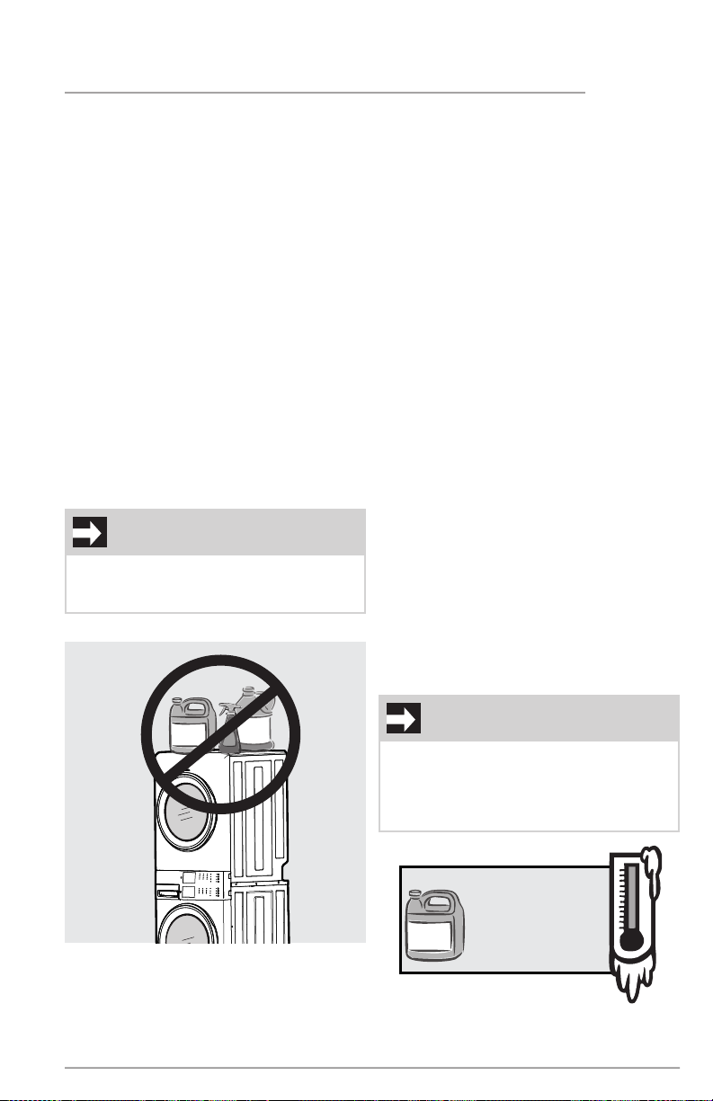
CARE AND CLEANING
Outside Routine Cleaning Winterizing Instructions
• When cycles have completed, wipe top
and sides of washer with a damp cloth.
• Clean the cabinet with mild soap
and water. Never use harsh, gritty or
abrasive cleansers
• If the cabinet becomes stained, clean
with diluted chlorine bleach (1 part
bleach to 8 parts water). Rinse several
times with clear water.
• Remove glue residue from tape or
labels with a mixture of warm water and
mild detergent. Or, touch residue with
the sticky side of tape.
• Use only a damp cloth when cleaning
chrome parts.
• Place a strip of cardboard or thin
fiberboard under the front leveling legs
before moving the laundry center to
prevent damage to the floor.
IMPORTANT
DO NOT store or place laundry products
on top of the laundry center at any time.
They can damage the finish or controls.
1. Turn off water supply faucets.
2. Disconnect hoses from water supply
and drain water from hoses. Vacuum
out each water supply inlet with
a waterproof utility vac to ensure
water valves are completely drained.
Damage will occur if water in water
inlet valves are allowed to freeze.
3. Plug electrical cord into a properly
grounded electrical outlet.
4. Add 1 gallon (3.8 L) nontoxic
recreational vehicle (RV) antifreeze to
empty wash drum. Close door.
5. Select any cycle. Press start/pause
and let the washer drain for 1 minute to
drain out all the water. Not all of the RV
antifreeze will be expelled.
6. Press cancel, unplug electrical power
cord, dry off drum interior and close
door.
7. Remove dispenser drawer. Drain
any water in compartments and dry
compartments. Replace drawer.
8. Store laundry center in an upright
position.
9. To remove antifreeze from laundry
center after storage, run empty
washer through a complete cycle with
detergent. DO NOT add wash load.
65
IMPORTANT
If the washer is stored in an area where
freezing can occur or moved in freezing
temperatures, follow these winterizing
instructions to prevent damage to the
washer:
Follow WINTERIZING INSTRUCTIONS
RV
ANTIFREEZE
for cold weather
storage and care.
Page 66
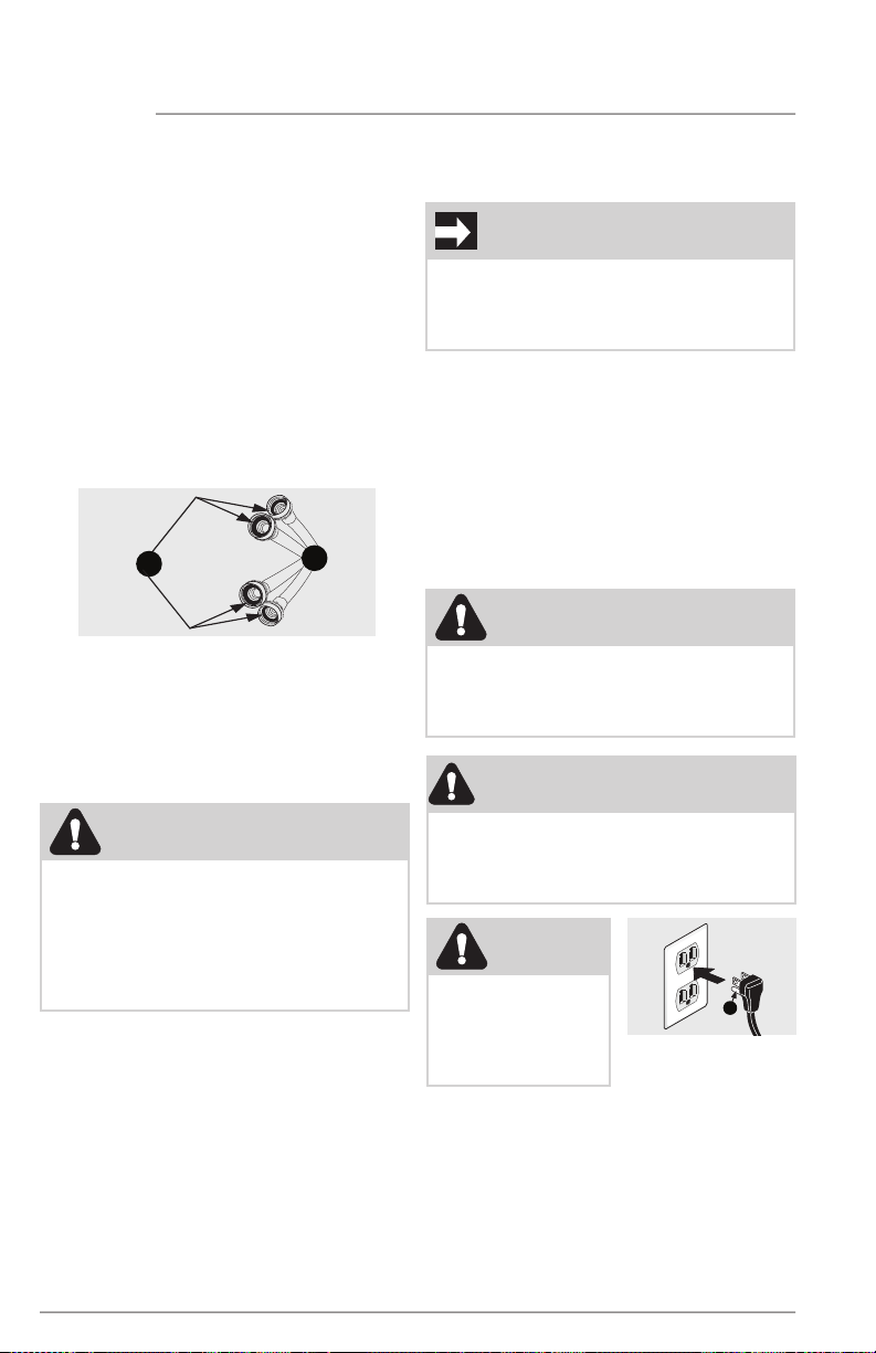
66
CARE AND CLEANING
Water Inlet Hose Inspection
Periodically inspect all water inlet hoses
for water leaks, wear, cuts, corrosion and
bulges. Replace all hoses, if any sign of
the above is visible. All hoses should be
replaced every 5 years to reduce the risk of
hose failures. When replacing hoses, refer to
the Installation sections of this Use & Care
Manual for proper installation instructions.
DO NOT over-tighten or cross thread the
fittings. DO NOT allow the hose to rub
against sharp objects. Always ensure the
hose fitting rubber gasket is installed and
free from water leaks when water pressure is
applied.
1
1. Rubber washers must be present
2. Replace hoses every 5 years
2
Instructions for Limited Use,
Vacation and Away from Home
Reconnecting Water Supply and
Electrical
IMPORTANT
When reinstalling the laundry center after
disconnecting the water supply lines and
electrical power, please follow the steps
below:
1. Review the
manual to ensure the appliance is level
and the water and electrical power
supply is properly connected.
2. Ensure the water lines are flushed of
debris, prior to connecting the water
lines to the washer inlet.
3. Check for water leaks and replace
supply hoses if needed.
Damaged or improperly installed water lines
can cause the water lines or connections to
leak. Water leakage is a safety issue and can
cause personal injury or property damage.
WARNING
Installation
CAUTION
section of this
CAUTION
Your laundry center should be operated
ONLY when you are home. Water leakage
is a safety issue and can cause personal
injury or property damage. Follow these
steps if you are away from home or not
using your laundry center for extended
periods of time.
1. Turn off the water supply to the laundry
center to avoid water leaks due to
unforeseen water pressure surges in the
water supply.
2. Disconnect or unplug the electrical
power to the laundry center.
3. Remove excess water from the
dispenser, interior door and tub and
perform the Care and Cleaning steps.
Improper grounding of the washer may
cause serious injury or death. Check with a
licensed electrician if you are in doubt as to
whether the appliance is properly grounded.
CAUTION
Do not, under any
circumstances, cut,
remove, or bypass
the grounding
prong.
1. Power cord with
grounded prong.
1
Page 67
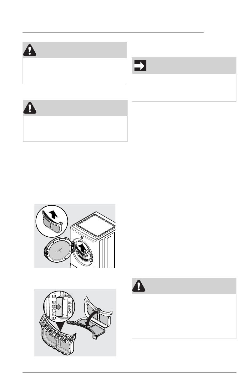
WARNING
CARE AND CLEANING
4. Snap the filter closed and place back
into the dryer opening.
67
To reduce risk of fire or serious injury to
persons or property, comply with the basic
warnings listed in the Important Safety
Information and those listed below.
Cleaning the Filter
WARNING
Clean the lint filter after every load.
CLEAN LINT will be displayed at the end
of the cycle to remind you to remove lint
from the filter.
Clean the lint filter after every load. Lint
build-up on the filter restricts air flow, which
causes longer drying times. The filter is
located at the bottom of the door opening.
Cleaning the LuxCareTM Lint Shield
Filter
1. Remove the filter by pulling it straight
up from the dryer opening.
2. Press down the button on the top of
the filter to open the clamshell.
IMPORTANT
• DO NOT open the clamshell filter
beyond the hinge limit.
• ALWAYS handle the clamshell filter by the
frame, not by the mesh material.
Inside
• Occasionally a waxy build-up may form
on the lint filter and/or moisture sensing
bars from using dryer-added fabric
softener sheets. To remove this build-up,
wash them with warm, soapy water. Dry
the filter thoroughly and replace.
• If the dryer drum becomes stained
from non colorfast fabrics, clean with a
damp cloth and a mild liquid household
cleanser. Remove cleanser residue
before drying the next load.
• Before cleaning the dryer drum interior,
unplug the electrical power cord to
avoid electrical shock hazards.
DO NOT use any type of spray cleanser
when cleaning the dryer interior.
Hazardous fumes or electrical shock
could occur.
• Every 18 months a qualified service
professional should clean the dryer
cabinet interior, lint screen housing
and exhaust duct. These areas can
collect lint and dust over time. An
excessive amount of lint build-up could
result in inefficient drying and possible
fire hazard.
WARNING
3. Gently clean the lint from the filter.
FIRE HAZARD
A clothes dryer produces combustible
lint. The dryer must be connected to an
outdoor exhaust. Regularly inspect the
outdoor exhaust opening and remove any
accumulation of lint around the opening
and in the surrounding area.
Page 68
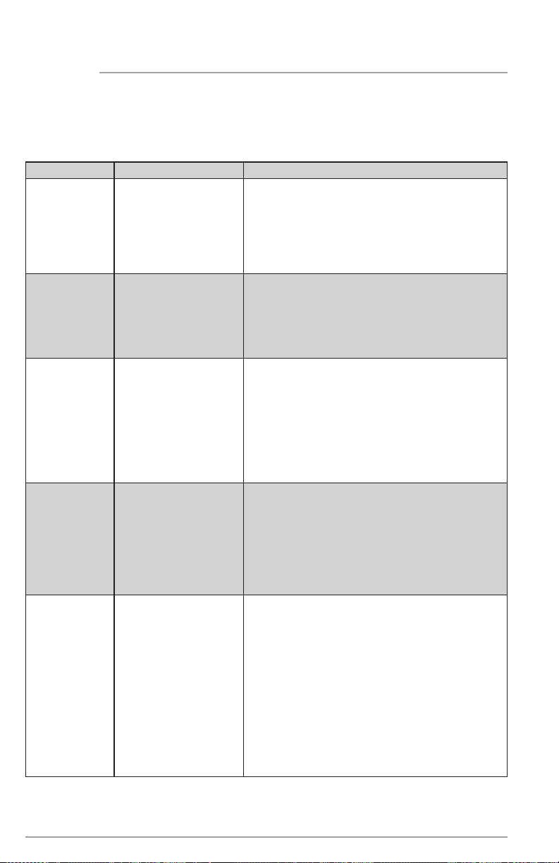
68
TROUBLESHOOTING
Common Washing Inquiries
Many washing problems involve poor soil and stain removal, residues of lint and scum, and
fabric damage. For satisfactory washing results, follow these suggestions provided by The
Soap and Detergent Association.
PROBLEM POSSIBLE CAUSES SOLUTIONS
Blue stains • Undiluted liquid
Discoloration,
graying
Greasy,
oily stains
Holes, tears, or
snags
Lint • Incorrect sorting.
detergent or fabric
softener dispensed
directly onto fabric.
• Not enough detergent.
• Wash water
temperature too low.
• Incorrect sorting.
• Not enough detergent.
• Undiluted liquid fabric
softener poured
directly on fabric.
• Incorrect use of
chlorine bleach.
• Unfastened zippers,
hooks, buckles.
• Rips, tears and broken
threads.
• Overloading washer.
• Degradation of fabric.
• Tissues left in pocket.
• Overloading washer.
• Not enough detergent.
• Undissolved detergent
has left a residue
resembling lint.
• Static cling is
attracting lint.
• Load washed too
long.
• If caused by detergent, mix 1 cup (240 ml) white
vinegar with 1 qt (.95 L) water in plastic container.
Soak 1 hour. Rinse.
• If caused by fabric softener, rub stains with bar
soap. Wash.
• Avoid overfilling detergent and fabric softener
compartments of dispenser.
• Rewash with correct amount of detergent and
hottest water safe for fabric.
• Add bleach safe for fabric.
• Sort items by soil level and color.
• Use correct amount of detergent, hottest water
and bleach safe for fabric.
• Treat with prewash stain remover or liquid
detergent.
• Increase detergent and water temperature.
Rewash.
• Rub fabric softener stains with bar soap.
• Use correct amount of detergent and hottest
water safe for fabric.
DO NOT pour liquid fabric softener directly on
fabric.
• May be irreversible if rips, tears and seams
cannot be mended.
• Never pour chlorine bleach directly on fabric.
• Check condition of items before washing.
• Reduce load size. Rewash using correct water
temperature, water level, and amount of
detergent.
• Add non-precipitating
water conditioner to wash water to remove
detergent residue.
• Add liquid fabric softener to final rinse.
• Dry load in dryer.
• Remove lint with lint brush or roller.
• See
Operating Your Washer
DO NOT overload washer.
• Use correct temperature and amount of
detergent, water and wash time.
.
Page 69
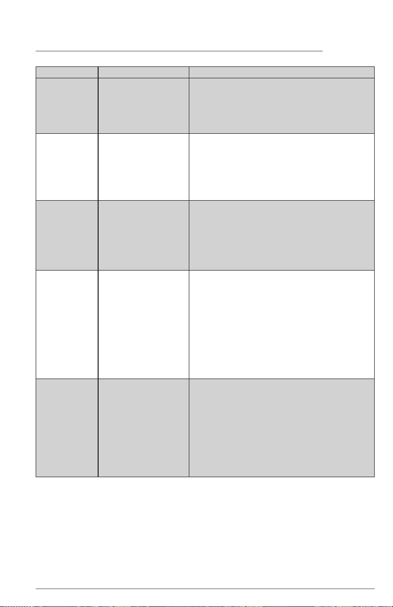
TROUBLESHOOTING
PROBLEM POSSIBLE CAUSES SOLUTIONS
Pilling
(Fibers ball up
and cling to
fabric.)
Residue or
powder on dark
items;
Stiff, harsh
fabrics.
Wrinkling • Overloading washer.
Yellow buildup
of body soil on
synthetic fabrics
Yellow or brown
rust stains
• Pilling is normal
with synthetic and
permanent press
fabrics. This is due to
abrasion from normal
wear.
• Undissolved detergent.
• Some granular
detergents can
combine with hard
water minerals to form
a residue.
• Overloading washer.
• Incorrect wash cycle
for wash load.
• Agitation time too
short.
• Wash water
temperature too low.
• Not enough detergent.
• Iron or manganese in
water supply, water
pipes, or water heater.
• Use a lint brush or shaver to remove pills.
• Use fabric softener in washer to lubricate fibers.
• When ironing, use spray starch or fabric finish on
collars and cuffs.
• Turn items inside out to reduce abrasion.
• Rewash load.
• Increase water temperature using hottest water
safe for fabric.
DO NOT overload washer.
• Use liquid detergent or non-precipitating water
conditioner with powder detergent.
• Reduce load size.
• Rinse in cold water with liquid fabric softener
using the casual or delicate cycle.
DO NOT overload washer.
• Remove items from washer as soon as cycle is
completed.
• Use liquid fabric softener.
• Soak in detergent booster or product containing
enzymes.
• Wash in hottest water safe for fabric using casual
cycle.
• Increase detergent.
• Add bleach safe for fabric or treat with color
remover.
• Select correct cycle.
• Use correct amount of detergent.
• Wash synthetics frequently using hot or warm
water.
• To restore discolored load of whites, use rust
remover safe for fabric.
DO NOT use chlorine bleach to remove rust
stains. It may intensify discoloration.
• Use non-precipitating water softener.
• Before washing, run hot water for a few minutes
to clear lines.
• Drain water heater occasionally.
• For an ongoing problem, install an iron filter in
your water supply system.
69
Page 70
70
TROUBLESHOOTING
PROBLEM POSSIBLE CAUSES SOLUTIONS
Residue stain
buildup in gasket
Residue stain
buildup in
dispenser drawer
or detergent pack
not dissolved.
Water in fold of
flexible gasket
Odor • Moisture in the washer.
• Moisture in washer.
• Use of non-HE
detergent.
• Overdosing detergent.
• Overloading wash
drum.
• Leaving a wet load set
in washer.
• Cold water washes
which may not
completely dissolve
and remove
detergents.
• Moisture in the washer.
• Use of non-HE
detergent.
• Overdosing detergent.
• Adding more than
two detergent packs
to detergent pack
compartment.
• PODS® option not
selected when using
detergent pack (on
select models).
• Result of washing
and part of normal
operation.
• Use of non-HE
detergent.
• Overdosing detergent.
• Leaving a wet load
remain in washer.
• Cold water washes
which may not
completely dissolve
and remove
detergents.
• Perform clean
washer cycle
• Scrub gasket with Comet™ Spray Gel Mildew
Stain Remover - use brush to remove stains.
• Use only HE (high efficiency detergent) along
with recommended dosage.
• Remove wash load immediately upon cycle
completion.
• Run dehumidifier in laundry room.
• Avoid overfilling detergent and fabric softener
compartments of dispenser.
• Dry the inside of washer and gasket after
every run.
• Remove and clean dispenser and inserts with
combination of ¾ cup liquid chlorine bleach
and one gallon hot water. Rinse well, and
repeat if necessary. NOTE: Wear rubber of
latex gloves. Protect floor and clothing from
bleach damage.
• Use only HE (high efficiency detergent) along
with recommended dosage.
• Avoid overfilling detergent and fabric softener
compartments of dispenser.
• Check that PODS® option is selected and
detergent pack is placed in PODS® dispenser
compartment when using detergent pack (on
select models).
• At the end of each wash, dry inside of gasket
fold with clean dry towel all around gasket.
• Perform clean
washer cycle.
• At the end of each wash, dry inside of gasket
fold with clean, dry towel all around gasket.
• Use only HE (high efficiency detergent) along
with recommended dosage.
• Remove wash load immediately upon cycle
completion.
• Pour one cup liquid chlorine bleach in
standpipe; let remain a day and flush with
water.
• Utilize the door stand ventilation feature for
a few hours after use or whenever washer is
not in use.
PODS® is a registered trademark of Procter & Gamble Company, Cincinnati OH, used under license by Electrolux.
Page 71
TROUBLESHOOTING
71
Before Calling
Before calling for service, review this list. It may save both time and expense. The list
includes common occurrences that are not the result of defective workmanship or materials
in this washer.
PROBLEM POSSIBLE CAUSES SOLUTIONS
NOISE (Please refer to
High pitch “jet
engine” noise
Rattling and
clanking noise
Thumping
sound
Vibrating noise • Washer is not resting firmly on
OPERATING
Residue left in
drum
LED displays
“ ”
Washer won’t
spin
LED Displays
“CLEAr door”
Normal Operating Sounds
• A certain amount of motor
whine is normal during the spin
cycle.
• Foreign objects such as coins
or safety pins may be in drum
or pump.
• Belt buckles and metal
fasteners are hitting wash drum.
• Heavy wash loads may
produce a thumping sound.
This is usually normal. If sound
continues, washer is probably
out of balance.
floor.
• Shipping bolts and foam block
have not been removed during
installation.
• Wash load unevenly distributed
in drum.
• Heavily soiled items. • Wipe drum with a nonabrasive
• Washer has been programmed
to temporarily perform a
repeating demo cycle.
• Load is too small. • Add 1 or 2 similar items to help
• Washer has detected
something trapped between
the door and door gasket.
)
• Stop washer and check drum. If no
objects are found, perform cycle
with empty drum. If noise continues,
item may be in pump. Call your
authorized service technician.
• To prevent unnecessary noise and
damage to drum, fasten fasteners
and turn items inside out.
• Stop washer and redistribute wash
load.
• Move washer so it rests firmly on
floor. Adjust leveling legs. See
Leveling the washer
• See Installation sections of this
manual for removing shipping bolts
and foam block.
• Stop washer and rearrange wash
load.
household cleanser, then rinse. Shake
or brush excess dirt and sand from
items before washing.
• Reset the unit back to factory default
settings.
1. Press power to turn off unit. Press
power again to turn unit on. Look for
console to light up.
2. Wait at least 10 seconds, then
simultaneously press and hold soil
and options buttons for 3 secs.
3. Lights will turn OFF and ON,
indicating the unit has been reset to
factory default
balance the load.
• Press the cancel button to unlock the
door, remove the trapped item, close
the door and restart the cycle.
for details.
Page 72
72
TROUBLESHOOTING
PROBLEM POSSIBLE CAUSES SOLUTIONS
Washer does
not start
WATER
Water collects in
folds of the door
gasket at the
end of the cycle
Water collects
in bleach and
fabric softener
compartments
Wash load too
wet after spin
Water does not
enter washer or
it enters slowly
• Electrical power cord may not be
plugged in or connection may be
loose.
• House fuse blown, circuit breaker
tripped, or a power outage has
occurred.
• Action of pressing start/pause
button on “touch screen” style
console not recognized.
• Water supply faucets are not
turned on.
• Motor is overheated. Washer
motor will stop if overheated.
• Door may be open. Unit will not
operate with door open.
• Light next to start/pause button is
flashing indicating unit is paused.
• This is a result of the washing
action and is part of the normal
operation of the washer.
• This is a result of the siphoning
action and is part of the normal
operation of the washer.
• Washer is overloaded.
• Load is too small.
• Load is out of balance.
• Drain hose is kinked.
• Water supply is not adequate in
area.
• Water supply faucets are not
completely open.
• Water is being used elsewhere in
the house. Water pressure must be
at least 30 psi (260 kPa).
• Water inlet hoses are kinked.
• Water inlet screens plugged.
• Make sure plug fits tightly in wall
outlet.
• Reset circuit breaker or replace
fuse. DO NOT increase fuse
capacity. If problem is a circuit
overload, have it corrected by a
qualified electrician. If problem is
a power outage, call local electric
company.
• Press start/pause button with bare
fingertip.
• Turn on water supply faucets.
• It will automatically restart after
a cool down period of up to 30
minutes (if washer has not been
manually turned off).
• Ensure door is closed.
• Press start/pause button to
continue the cycle.
• Wipe and dry the gasket to
remove water and any debris
remaining in the gasket after use.
• Water may be removed by
removing the dispenser drawer
(see
Care and Cleaning
manual) and draining water into
the empty drum or sink.
DO NOT overload washer. See
Operating Your Washer.
• Add 1 or 2 similar items to help
balance load.
• Rearrange load to allow proper
spinning.
• Straighten drain hose.
• Check another faucet in the
house. Wait until water supply and
pressure increase.
• Fully open hot and cold faucets.
• Avoid running water elsewhere
while washer is filling.
• Straighten hoses.
• Remove hose from inlets and
clean screens.
in this
Page 73
TROUBLESHOOTING
PROBLEM POSSIBLE CAUSES SOLUTIONS
Warm or hot
water is not hot
enough
Water in washer
does not drain
or drains slowly
Water leaks • Fill hose connection is loose at
Over-sudsing • HE detergent is not being used.
Incorrect wash
and rinse temperatures. The
LED display will
alert this condition with “HOSE”
alarm
Water is entering washer but
tub does not fill
• Hot water heater is set too low or
is a distance from washer.
• Hot water is being used
elsewhere in the house.
• Drain hose is kinked or clogged.
• Drain hose standpipe is too tall.
Maximum standpipe height is 8’
(2.4 m).
• House drain pipes are clogged.
faucet or washer.
• Dispenser drawer not completely
closed
• Water hoses have damage, cuts
or corrosion.
• Too much detergent.
• Hot and cold water hoses are
connected to wrong supply
faucets.
• Drain hose standpipe is too low.
Standpipe must be a min of 23.6”
(60 cm) high to prevent siphoning.
• Measure hot water temperature at
nearby faucet with candy or meat
thermometer. Water temperature
should be at least 120°F (49°C).
Adjust water heater as necessary.
• Avoid using hot water elsewhere
before or during washer use. There
may not be enough hot water
available for proper cleaning. If
problem persists, your hot water
system may be unable to support
more than 1 use at a time.
• Clean and straighten the drain
hose.
• Reduce standpipe height to less
than 8’ (2.4 m). See Installation
sections of this manual.
• Unclog drain pipes. Contact
plumber if necessary.
• Check and tighten hose
connections. Install rubber sealing
washers provided.
• Close dispenser drawer
completely.
• Replace hoses.
• Run rinse cycle. Use a lowsudsing, high efficiency detergent.
• Run rinse cycle. Use less detergent
in future loads.
• Connect hot water hose to hot
water faucet and cold water hose
to cold water faucet.
• Increase standpipe height
to at least 23.6” (60 cm). See
Installation sections of this
manual.
73
Page 74
74
TROUBLESHOOTING
Common Drying Inquiries
Many drying problems involve poor cleaning results, poor soil and stain removal,
residues of lint and scum, and fabric damage. For satisfactory drying results, follow these
suggestions provided by The Soap and Detergent Association.
PROBLEM POSSIBLE CAUSES SOLUTIONS
Greasy, oily
stains
Lint • Overloading
Pilling (fibers
break off,
ball up and
cling to
fabric)
Shrinking • Temperature too
Wrinkling • Overloading
Isolated wet
spots on
fabrics after
completed
Steam cycle
• Fabric softener
sheet
• Over-drying causes
static electricity
• Lint screen not
clean when cycle
began
• Lint is attached to
“pills”
• Over-drying • Use a lint brush or shaver to remove pills.
high
• Over-drying
• Leaving items in
dryer after cycle
ends
• Low water pressure
in home is not
sufficient to atomize
incoming water
during steam cycle
• Rub fabric softener stains with bar soap. Rinse
and rewash.
• Add a few bath towels to small loads for proper
tumbling.
• Some “silk-like” fabrics should be air dried.
• Use proper drying temperature.
• Place fabric softener sheet on top of load before
starting the dryer.
• Reduce load size and rewash using liquid fabric
softener in the final rinse.
• Or, add a fabric softener sheet and tumble without
heat.
• Use lint brush or roller to remove lint.
• DO NOT overload dryer.
• Use fabric softener in washer or dryer to reduce
static electricity.
• Remove items when they are slightly damp to
avoid over-drying.
• Check that lint filter is clean and in place.
• Use fabric softener to lubricate fibers.
• When ironing, use spray starch or fabric finish on
collars and cuffs.
• Turn items inside out to reduce abrasion.
• Irreversible condition.
• Follow fabric care label directions.
• If shrinking is a concern, check load often.
• Remove items while slightly damp and hang or lay
flat to complete drying.
• Block knits into shape.
• Reduce load size and tumble at medium or low
heat for 5-10 minutes.
• Remove items immediately. Hang or fold.
• DO NOT overload dryer.
• Remove items as soon as cycle ends.
• Check water line pressure.
• Ensure water line pressure is minimum of 20 psi.
DO NOT exceed 120 psi.
Page 75
TROUBLESHOOTING
75
Before Calling
Before calling for service, review this list. It may save both time and expense. The list
includes common occurrences that are not the result of defective workmanship or materials
in this dryer.
PROBLEM POSSIBLE CAUSES SOLUTIONS
Dryer does
not start.
• Electrical power cord is not
securely plugged in or plug
may be loose.
• House fuse blown or circuit
breaker tripped.
• Action of pressing start
button on “touch screen”
style console not recognized
• Thermal limiter tripped.
• Make sure the plug fits tightly in
wall outlet.
• Reset circuit breaker or replace
fuse.
• Make sure electrical line is not
overloaded and the dryer is on a
separate circuit.
• Press start button with bare
fingertip.
LED
displays
” ”.
Dryer runs but
won’t heat.
• Delay time inadvertently
activated.
• Door may be open. Unit will
not operate with door open.
• Difficult load to dry.
• Dryer has been
programmed to temporarily
perform a repeating demo
cycle.
• There are 2 house fuses in
the dryer circuit. If 1 of the 2
fuses is blown, the drum may
turn but the heater will not
operate (electric models).
• Gas supply valve is not open
(gas models).
• Dryer does not have enough
air supply to support the
burner flame (gas models).
• LP gas supply tank is empty
or there has been a utility
interruption of natural gas
(gas models).
• Call authorized service person for
replacement.
• Ensure delay time not activated.
• Ensure door is closed.
• Select Dry Boost option
• Reset the unit back to factory
default settings as described
earlier.
• Replace fuse.
• Check to make sure supply valve
is open. Refer to the installation
instructions provided with the
dryer.
• See the Installation sections of
this manual.
• Refill or replace tank. Dryer
should heat when utility service is
restored.
Page 76
76
TROUBLESHOOTING
PROBLEM POSSIBLE CAUSES SOLUTIONS
Drying cycle
takes too long,
outside of the
dryer feels too
hot or smells
hot.
Excess
moisture in
drum between
cycles.
Excessive
wrinkling.
Scratching or
chipping of the
drum finish.
* Drum damage caused by foreign objects or permanently attached
items is not covered by the warranty.
• Lint filter is clogged with
lint.
• Exhaust duct requirements
have not been met.
• Electric dryer is connected
to a 208 volt circuit.
• Drying procedures have
not been followed.
• Outside exhaust hood
or exhaust duct may be
clogged or restricted.
• High humidity.
• Exhaust damper stuck
open or not present.
• Dryer is overloaded.
• Items left in dryer too long.
• Insufficient sorting of items.
• Drying temperature too
high.
• Drying load is very small.
• Foreign objects such as
coins, pins, clips or buttons
are inside the dryer.*
• Permanently attached
items such as belt buckles,
zippers and fasteners may
be hitting the inside of the
drum.*
• Make sure all lint has been removed
from the dryer lint filter before
starting each cycle.
• Exhaust duct must be at least 4
inches in diameter and made of
rigid or semi-rigid metal.
• When in place, the duct must
not exceed length listed in the
installation instructions.
• Drying time will be 20% longer than
drying on a 240 volt circuit.
• See Operating Instructions.
• Clean out any obstruction.
• Use a dehumidifier near the dryer.
• Fix or clean the damper, or install
new one.
• DO NOT overload. See Operating
Instructions.
• Remove items as soon as cycle
ends.
• See Operating Instructions.
• Follow fabric care label instructions.
• Add two or three larger items.
• Always remove foreign objects from
pockets before laundering. Remove
objects from drum and restart dryer.
• It may be necessary to sew a
scrap of material securely around
ornaments before drying to prevent
scratching and damage to the
dryer.
Page 77

LIMITED WARRANTY
For the applicable warranty period as set forth below, as measured from your original date of purchase,
Electrolux will repair or replace any parts of this appliance that prove to be defective in materials or
workmanship when such appliance is installed, used and maintained in accordance with the provided
instructions.
Warranty Periods:
• All parts — One year including labor. In addition, your appliance is covered by a one year, parts only,
limited warranty. During the 2nd year from your original date of purchase, Electrolux will pay for parts
needed for this appliance that have proven to be defective in materials or workmanship when your
appliance is installed, used, and maintained in accordance with the provided instructions.
Exclusions
This warranty does not cover the following:
1. Products with original serial numbers that have been removed, altered or cannot be readily determined.
2. Product that has been transferred from its original owner to another party or removed outside the USA or Canada.
3. Rust on the interior or exterior of the unit.
4. Products purchased “as-is” are not covered by this warranty.
5. Products used in a commercial setting.
6. Service calls which DO NOT involve malfunction or defects in materials or workmanship, or for appliances not in
ordinary household use or used other than in accordance with the provided instructions.
7. Service calls to correct the installation of your appliance or to instruct you how to use your appliance.
8. Expenses for making the appliance accessible for servicing, such as removal of trim, cupboards, shelves, etc., which
are not a part of the appliance when it is shipped from the factory.
9. Service calls to repair or replace appliance light bulbs, air filters, water filters, other consumables, or knobs, handles,
or other cosmetic parts.
10. Pickup and delivery costs; your appliance is designed to be repaired in the home.
11. Surcharges including, but not limited to, any after hour, weekend, or holiday service calls, tolls, ferry trip charges, or
mileage expense for service calls to remote areas, including the state of Alaska.
12. Damages to the finish of appliance or home incurred during transportation or installation, including but not limited
to floors, cabinets, walls, etc.
13. Damages caused by: services performed by unauthorized service companies; use of parts other than genuine
Electrolux parts or parts obtained from persons other than authorized service companies; or external causes such
as abuse, misuse, inadequate power supply, accidents, fires, or acts
DISCLAIMER OF IMPLIED WARRANTIES; LIMITATION OF REMEDIES
CUSTOMER’S SOLE AND EXCLUSIVE REMEDY UNDER THIS LIMITED WARRANTY SHALL BE REPAIR
OR REPLACEMENT AS PROVIDED HEREIN. CLAIMS BASED ON IMPLIED WARRANTIES, INCLUDING
WARRANTIES OF MERCHANTABILITY OR FITNESS FOR A PARTICULAR PURPOSE, ARE LIMITED TO ONE
YEAR OR THE SHORTEST PERIOD ALLOWED BY LAW, BUT NOT LESS THAN ONE YEAR. ELECTROLUX SHALL
NOT BE LIABLE FOR CONSEQUENTIAL OR INCIDENTAL DAMAGES SUCH AS PROPERTY DAMAGE AND
INCIDENTAL EXPENSES RESULTING FROM ANY BREACH OF THIS WRITTEN LIMITED WARRANTY OR ANY
IMPLIED WARRANTY. SOME STATES AND PROVINCES DO NOT ALLOW THE EXCLUSION OR LIMITATION
OF INCIDENTAL OR CONSEQUENTIAL DAMAGES, OR LIMITATIONS ON THE DURATION OF IMPLIED
WARRANTIES, SO THESE LIMITATIONS OR EXCLUSIONS MAY NOT APPLY TO YOU. THIS WRITTEN WARRANTY
GIVES YOU SPECIFIC LEGAL RIGHTS. YOU MAY ALSO HAVE OTHER RIGHTS THAT VARY FROM STATE TO STATE.
If You Need Service
Keep your receipt, delivery slip, or some other appropriate payment record to establish the warranty
period should service be required. If service is performed, it is in your best interest to obtain and keep
all receipts. Service under this warranty must be obtained by contacting Electrolux at the addresses or
phone numbers below.
This warranty only applies in the USA, Puerto Rico and Canada. In the USA and Puerto Rico, your
appliance is warranted by Electrolux Major Appliances North America, a division of Electrolux Home
Products, Inc. In Canada, your appliance is warranted by Electrolux Canada Corp. Electrolux authorizes
no person to change or add to any obligations under this warranty. Obligations for service and parts
under this warranty must be performed by Electrolux or an authorized service company. Product features
or specifications as described or illustrated are subject to change without notice.
of God.
77
USA
1-877-435-3287
Electrolux Home Products, Inc.,
North America
10200 David Taylor Drive
Charlotte, NC 28262
Canada
Electrolux Canada Corp.
Mississauga, Ontario, Canada
1-800-265-8352
5855 Terry Fox Way
L5V 3E4
Page 78

A23623503 (August 2023)
electrolux.com
 Loading...