

Page 1
Gas cookers
INSTRUCTION BOOKLET
Please read this instruction booklet before using the appliance
35673-8302
Mod. EK 5701
GB
1
Page 2

Important Safety Information
You MUST read these warnings carefully before installing or using the appliance. If you
need assistance, contact our Customer Care Department on 08705 950950
Installation
l This cooker must be installed by qualified
personnel, according to the manufacturers
instructions and to the relevant British
Standards.
This cooker is heavy. Take care when moving it.
l Any gas installation must be carried out by a
registered CORGI installer.
l Remove all packaging before using the cooker.
l Ensure that the gas and electrical supply
complies with the type stated on the rating plate,
located near the gas supply pipe.
l Do not attempt to modify the cooker in any way.
Child Safety
l This cooker is designed to be operated by
adults. Do not allow children to play near or with
the cooker.
l The cooker gets hot when it is in use. Children
should be kept away until it has cooled.
l Children can also injure themselves by pulling
pans or pots off the cooker.
During Use
l This cooker is intended for domestic cooking
only. It is not designed for commercial or
industrial purposes.
l When in use a gas cooker will produce heat
and moisture in the room in which it has been
installed. Ensure there is a continuous air supply,
keeping air vents in good condition or installing
a cooker hood with a venting hose.
l When using the cooker for a long period time,
the ventilation should be improved, by opening
a window or increasing the extractor speed.
l Do not use this cooker if it is in contact with
water. Do not operate the cooker with wet hands.
l Ensure the control knobs are in the OFF
position when not in use.
l Do not store flammable materials such as oven
gloves, tea towels etc. in the drawer.
l When using other electrical appliances, ensure
the cable does not come into contact with the
hot surfaces of the cooker.
l Unstable or misshapen pans should not be used
on the hob burners as unstable pans can cause an accident by tipping or spillage.
l Never leave the cooker unattended when
cooking with oil and fats.
l This cooker should be kept clean at all times.
A build-up of fats or foodstuffs could result in a
fire.
l Never use plastic dishes in the oven or on the
hob burners.
Never line any part of the oven with
aluminium foil.
l Always ensure that the oven vent which is
located at the centre back of the hob is left
unobstructed to ensure ventilation of the oven
cavity.
l Perishable food, plastic items and areosols may
be affected by heat and should not be stored
above the cooker.
l The appliance (EK 5701 W/GR only) is fitted
with a lid: this is designed as a dust cover when
closed, and as a splash-back when open. Do
not use for any other purpose.
l After using the cooker (EK 5701 W/GR only),
the lid MUST NOT be closed until the hob and
oven are completely cold. Do not use the lid to
switch off the gas supply. The gas supply should
always be turned off with the control knob.
Service
l This cooker should only be repaired or serviced
by an authorised Service Engineer and only genuine approved spare parts should be used.
Environmental Information
l After installation, please dispose of the
packaging with due regard to safety and the
environment.
l When disposing of an old appliance, make it
unusable, by cutting off the cable.
Keep this instruction book for future reference and
ensure it is passed on to any new owner.
These instructions are valid for UK only.
2
Page 3
Contents
For the User
Important Safety Information ............................ 2
Description of the Cooker ................................. 4
Control Panel.................................................... 5
Operation ......................................................... 6
Hob burners ............................................................. 6
Gas Oven ................................................................. 7
Before the First Use of the Cooker ................... 7
Using the Oven................................................. 8
Using the Gas oven .......................................... 9
Oven light pushbutton ............................................... 9
Gas Oven Cooking Charts ............................. 10
Grilling ............................................................ 12
Maintenance and Cleaning ............................. 13
Cleaning the Oven .......................................... 14
For the Installer
Instructions for the Installer ............................ 20
Important Safety Requirements...................... 21
Installation ...................................................... 22
Electrical connections .................................... 24
Commissioning .............................................. 25
Conversion from Natural to LPG Gas............. 26
Something Not Working ................................. 16
Guide to Use the instructions
The following symbols will be found in the text to
guide you throughout the Instructions:
Safety Instructions
F
Step by step instructions for an
operation
Hints and Tips
Environmental information
This appliance is manufactured
according to the following EEC
directives:
73/23 EEC - 90/683 EEC - 93/68 EEC 89/336 EEC - 90/396 EEC,
current edition.
3
Page 4
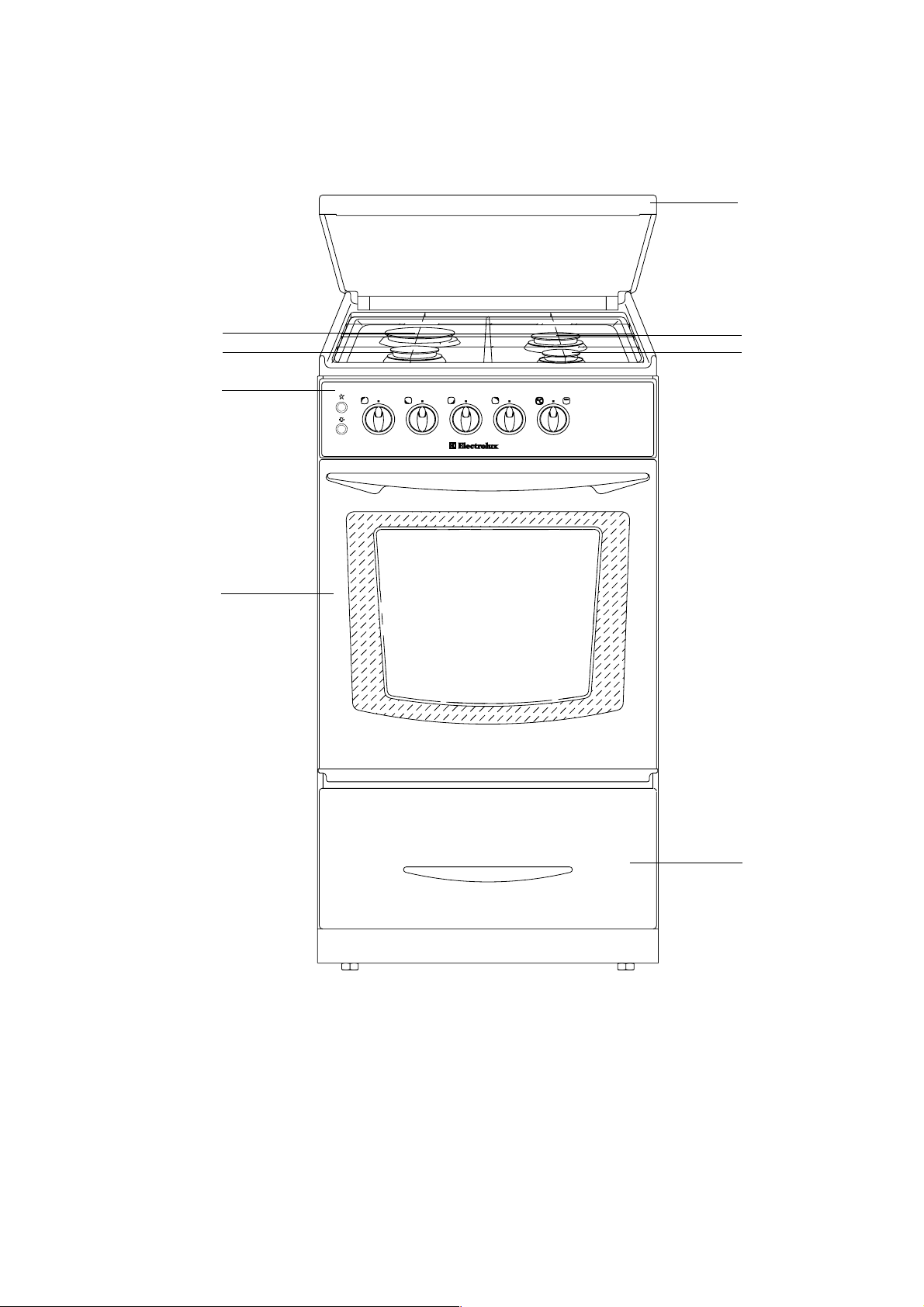
Description of the Cooker
Rapid burner
Semi-rapid burner
Cooker lid
(EK 5701 W/GR only)
Semi-rapid
burner
Auxiliary burner
Control panel
Oven door
front left
back left back rightfront right
grill and oven
Premier
Storage
drawer
4
Page 5
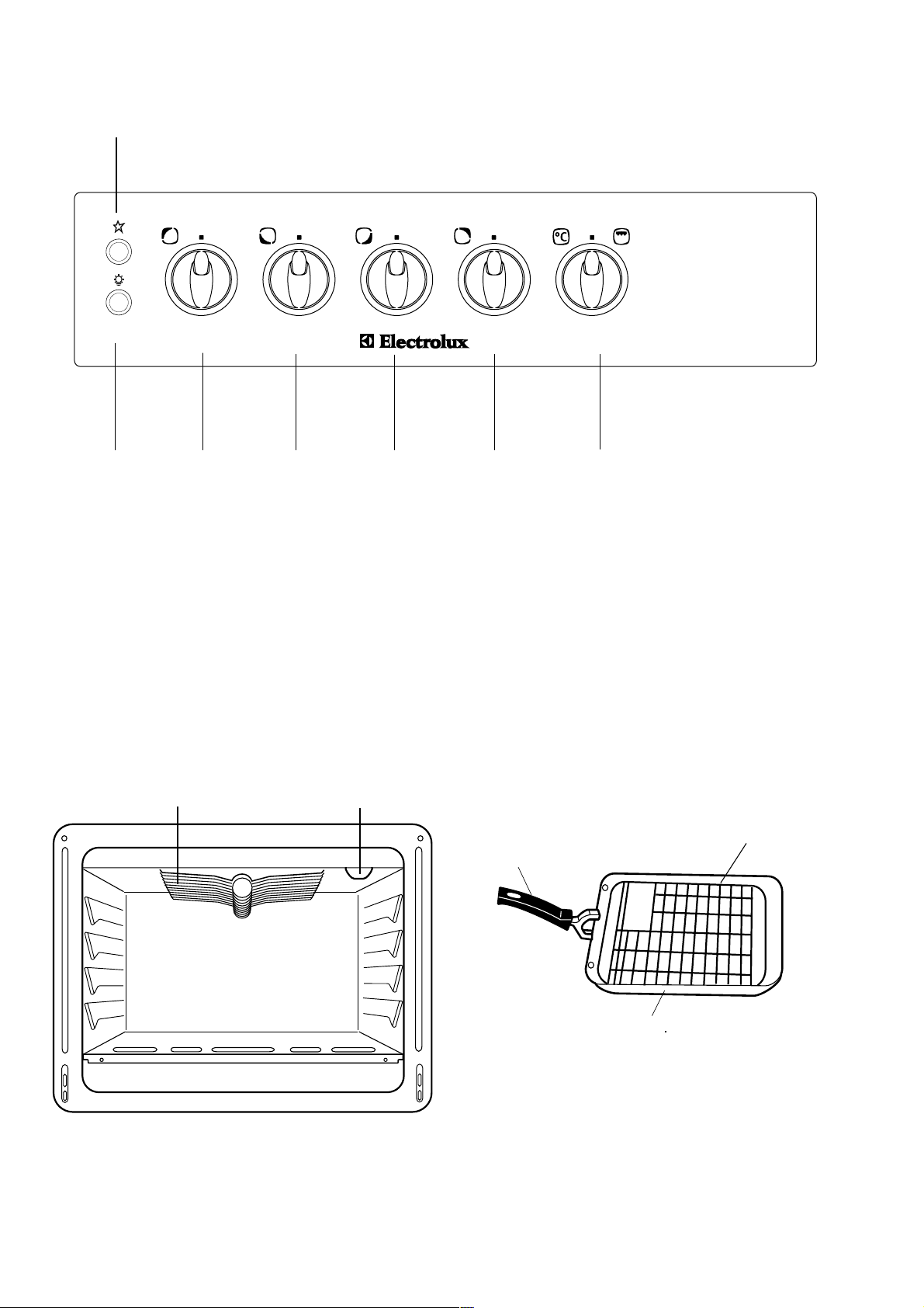
Control Panel
1
back left back rightfront right
2
3
front left
1. Electric Ignition push button
2. Oven Light push button
3. Back left burner control knob (rapid)
4. Front left burner control knob (semi-rapid)
5. Front right burner control knob (auxiliary)
6. Back right burner control knob (semi-rapid)
7. Oven function control knob
grill and oven
Premier
7654
The Oven Cavity
Gas Grill
Oven Light
FO 2440
Accessories
Removable handle
Q
Grill/roasting pan
P
Grill trivet
5
Page 6
Operation
Hob burners
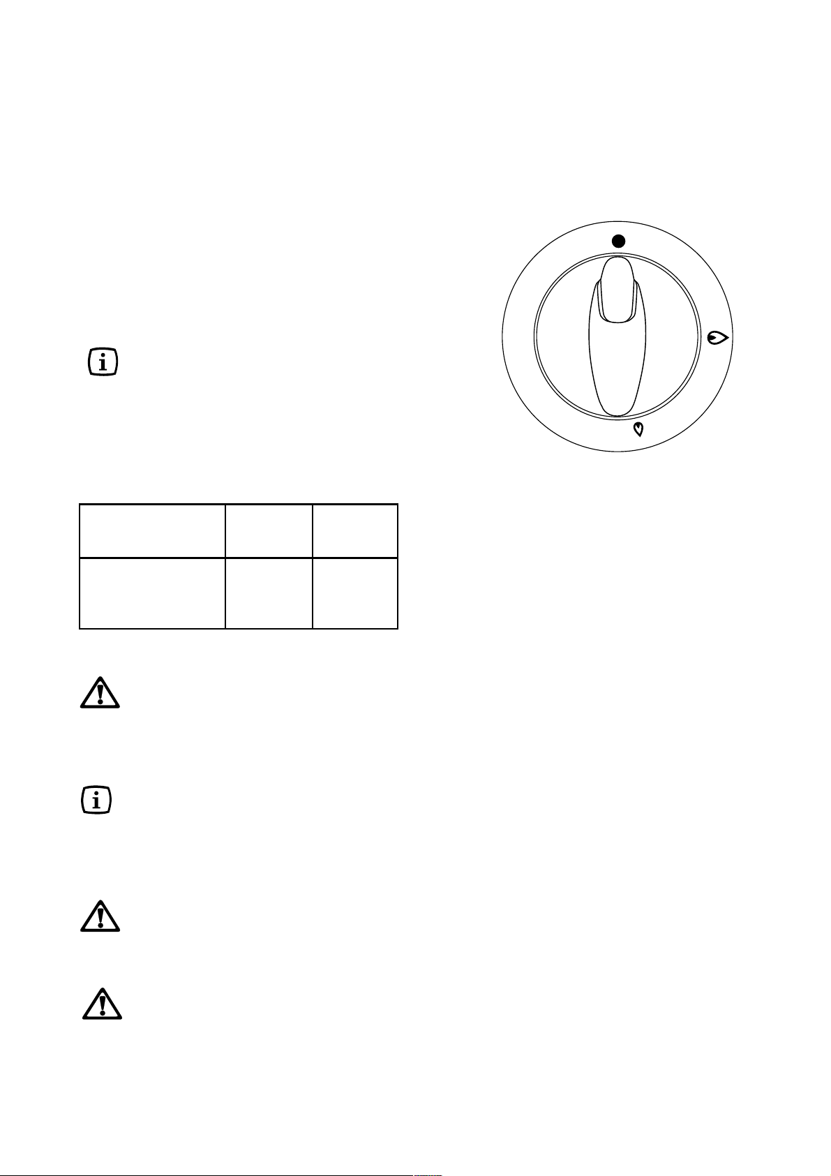
To light a burner, push in and turn the relevant
control knob anticlockwise to maximum position.
At the same time push the electric ignition button
which is marked with a little spark. Then adjust
the flame as required.
If the burner does not ignite, turn the control knob
to zero, and try again.
When switching on the mains, after
installation or a power cut, it is quite
normal for the spark generator to be
activated automatically.
To ensure maximum burner efficiency, you
should only use pots and pans with a flat bottom
fitting the size of the burner used (see table).
Burner minimum maximum
diameter diameter
Large (rapid) 180 mm. 260 mm.
Medium (semi-rapid) 120 mm. 220 mm.
Small (Auxiliary) 80 mm. 160 mm.
If you use a saucepan which is smaller
than the recommended size, the flame
will spread beyond the bottom of the
pan, causing the handle to overheat.
As soon as a liquid starts boiling, turn
down the flame so that it will barely keep
the liquid simmering.
Take care when frying food in hot oil or
fat, as the overheated splashes could
easily ignite.
If the control knobs become difficult to
turn, please contact your local
Electrolux Service Centre.
6
Page 7
Gas Oven
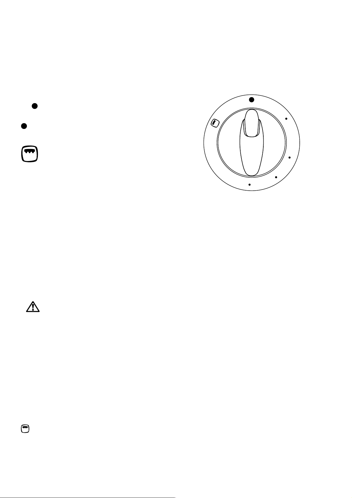
Oven Function Control Knob
Oven switched off
-max Range of temperature regulation for
conventional cooking
Grill - The heat comes only from the
top element
max
0
4
2
0
0
2
0
6
1
1
4
0
Before the First Use of the Cooker
Remove all packaging, both inside and
outside the cooker, before using it.
Before first use, the oven should be heated
without food. During this time, an unpleasant
odour may be emitted. This is quite normal.
F
This procedure should be repeated with the grill
1. Ignite the gas oven burner (see page
9) and set the oven function control
knob to MAX.
2. Open a window for ventilation.
3. Allow the oven to run empty for
approximately 45 minutes.
function for approximately 5-10 minutes.
7
Page 8
Using the Oven
Always cook with the oven door closed.
Stand clear when opening the drop down
oven door. Do not allow it to fall open support the door using the door handle, until
it is fully open.
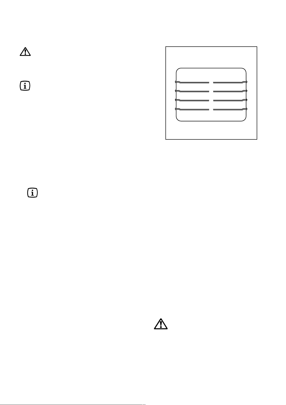
The oven has four shelf levels, and is
supplied with one shelf.
The shelf positions are counted from the
bottom of the oven as shown in the
diagram.
It is important that the shelf is correctly
positioned as shown in the diagram.
Do not place cookware directly on the oven
base.
When cooking in the oven (EK 5701 W/GR
only), always leave the cooker lid open, in
order to avoid overheating.
4
3
2
1
Hints and Tips
Condensation and steam
When food is heated it produces steam in the
same way as a boiling kettle. The oven vents
allow some of this steam to escape. However,
always stand back from the oven when opening
the oven door to allow any build up of steam or
heat to release.
If the steam comes into contact with a cool
surface on the outside of the oven, e.g. a trim, it
will condense and produce water droplets. This
is quite normal and is not a fault with the oven.
To prevent discoloration, regularly wipe away
condensation and also soilage from surfaces.
Cookware
Use any oven proof cookware which will
withstand temperatures of 250°C.
Baking trays, oven dishes, etc. should not be
placed directly against the grid covering the
fan at the back of the oven, or placed on the
oven base.
Do not use baking trays larger than 30 cm x
35 cm (12 in x 14 in) as they will restrict the
circulation of heat and may affect performance.
8
The effects of dishes
on cooking results
Dishes and tins vary in their thickness,
conductivity, colour, etc. which affects the way
they transmit heat to the food inside them.
A Aluminium, earthenware, oven glassware and
bright shiny utensils reduce cooking and
underneath browning.
B Enamelled cast iron, anodized aluminium,
aluminium with non-stick interior and coloured
exterior and dark, heavy utensils increase
cooking and underneath browning.
Storage Drawer
The storage drawer is located underneath the
oven cavity.
During cooking the storage drawer may
become hot if the oven is on high for a long
period of time, therefore flammable
materials such as oven gloves, tea towels,
plastic aprons etc. should not be stored in
the drawer.
Oven accessories such as baking sheets,
will also become hot, therefore care
should be taken when removing these
items from the drawer whilst the oven is in
use or still hot.
Page 9
Using the Gas oven
Before using your oven
Switch the oven to MAX. and leave it to run
empty for about 30 minutes to remove any
unpleasant smell.
During cooking, the door should be opened as
little as possible to avoid heat loss, and
excessive fuel consumption.
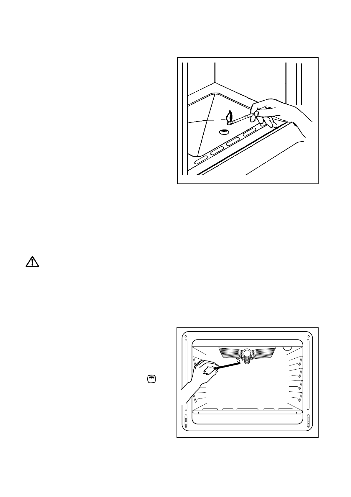
F To ignite the oven gas burner:
1. Open the oven door.
2. Hold a flame to the right-hand side hole
(see fig.)
3. Press the oven control knob and turn it
anti-clockwise until the maximum
temperature is reached.
4. Firmly press the oven control knob for
approximately 5 seconds, until the
safety valve automatically keeps the
oven burner lit.
5. Release the control knob and then
gently close the oven door. To adjust
the temperature, turn the knob to the
required setting after a few minutes.
If the oven burner accidentally goes out,
turn the oven knob to "O" and wait at least
1 minute before trying to light the burner
again.
FO 1079 REV
Oven safety device
The cooker features a thermocouple; if for any
reason the flame should extinguish, the device
will stop the gas flow.
Oven light pushbutton
This button will turn the oven light on.
Grill burner ignition
1. Open the oven door.
2. Hold a flame to the gas grill burner holes (see
fig.).
3. Press the oven control knob and turn it to
4. Firmly press the oven control knob for
approximately 5 seconds, until the safety
valve automatically keeps the grill burner lit.
If the burner does not ignite, turn the control knob
to zero, and try again.
.
FO 0829
9
Page 10

Gas Oven Cooking Charts
This chart is intended as a guide only. It may be necessary to increase or decrease the temperature to
suit your individual requirements. Only experience will enable you to determine the correct setting for
your personal requirements.
TEMPERATURE °C FOOD
MEAT & POULTRY
Beef with bone 160 2 or 3 20 minutes per lb
Beef without bone 190 2 or 3 25 minutes per lb
Lamb 160 2 or 3 20-25 minutes per lb
Pork 175 2 or 3 25 minutes per lb
Chicken 190 2 or 3 25 minutes per lb
Duckling 160 2 or 3 30 minutes per lb
Turkey 150 2 or 3 30 minutes per lb
Casseroles 135 2 or 3 21/2 hours
YORKSHIRE
PUDDING
Small 200 2 or 3 25 minutes
Large 200 2 or 3 35 minutes
SHELF COOKING
POSITIONS TIME
+ 20 minutes
+ 25 minutes
+ 20-25 minutes
+ 25 minutes
+ 25 minutes
+ 30 minutes
+ 30 minutes
BAKED
VEGETABLES 160 2 varies according to
the vegetable
PASTRY
Fruit Tart 175 2 35 minutes
Fruit Pie 175 2 or 3 35 minutes
Sausage Rolls 200 2 or 3 20 minutes
Choux Pastry 190 2 or 3 25-30 minutes
Vol au Vents 200 2 or 3 15 minutes
Jam Tarts 200 2 or 3 10-15 minutes
10
Page 11

Gas Oven Cooking Charts
This chart is intended as a guide only. It may be necessary to increase or decrease the temperature to
suit your individual requirements. Only experience will enable you to determine the correct setting for
your personal requirements.
TEMPERATURE °C FOOD
PUDDINGS
Egg Custard in a
Bain Marie 135 2 or 3 1-1 1/4 hours
Pavlova 135 2 or 3 1 1/2 hours
Meringues 135 2 or 3 1 1/2 hours
CAKES
Rich Fruit 150 2 or 3 3 1/2-4 hours
Cake 8" 150 2 or 3
Plain Fruit Cake 160 2 or 3 2 1/2 hours
Victoria
Sandwich 175 2 or 3 25-35 minutes
Madeira Cake 160 2 or 3 1 3/4-2 hours
Small Cakes 160 3 20-30 minutes
Ginger Bread 160 3 35-45 minutes
Flapjack 160 3 20-25 minutes
SHELF COOKING
POSITION TIME
YEAST MIXTURES
Bread
1lb Loaves 200 2 or 3 30-40 minutes
Bread
2lb Loaves 200 2 or 3 40-50 minutes
Rolls and Buns 200 2 or 3 15-20 minutes
Tea Rings 190 2 or 3 25-35 minutes
Scones 200 2 or 3 15-20 minutes
Shortbread 160 25-35 minutes
2 or 3 Change
trays over halfway
through the
cooking time
11
Page 12
Grilling
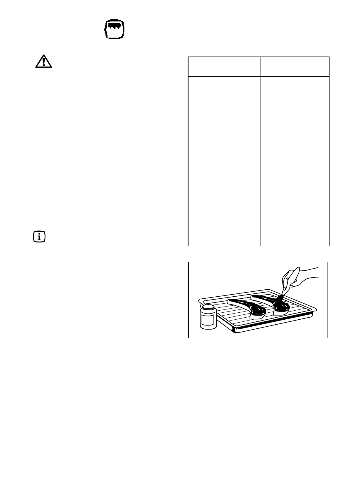
Grilling must be carried out with the oven
door closed. The grill pan handle must
be removed from the pan.
F How to Use the Grill
1. Ignite the grill burner as explained at page 9.
2. Adjust the grid and grill pan runner position to
allow for different thicknesses of food.
Position the food close to the element for
faster cooking and further away for more
gentle cooking.
Preheat the grill for a few minutes before
sealing steaks or toasting. Adjust the shelf level
as necessary, during cooking.
Food
Bacon rashers 2-3 each side
Beefburgers 6-10 each side
Chicken joints 10-15 each side
Chops: 7-10 each side
Fish: 8-12 each side
Kebabs 10-15 each side
Kidneys: 4-6 each side
Liver: 5-10 each side
Sausages 10-15 turn as required
Steaks: 3-6 each side
lamb
pork
whole trout/herring
fillets plaice/cod
lamb/pig
lamb/pig
rare
medium
well
10-15 each side
Grill
Time (Min)
4-6 each side
6-8 each side
7-10 each side
Hints and Tips
- Most foods should be placed on the grid in the
grill pan to allow maximum circulation of air to
lift the food out of the fats and juices. Food such
as fish, liver and kidneys may be placed directly
on the grill pan, if preferred.
- Food should be thoroughly dried before grilling
to minimise splashing. Brush lean meats and
fish lightly with a little oil or melted butter to keep
them moist during cooking.
- Accompaniments such as tomatoes and
mushrooms may be placed underneath the
grid when grilling meats
- When toasting bread, we suggest that the top
runner position is used.
- The food should be turned over during cooking,
as required.
- When grilling, we suggest that the dripping pan
is placed directly on the oven base. The
dripping pan prevents splashes of fat from
soiling the floor of the oven.
Browning only 3-5
O
L
I
12
Page 13
Maintenance and Cleaning
Before any maintenance or cleaning
can be carried out, you must
DISCONNECT the cooker from the
electricity supply.
The Hob Top
The hob is best cleaned whilst it is still warm, as
spillage can be removed more easily than if it is
left to cool.
Regularly wipe over the hob top using a soft cloth
well wrung out in warm water to which a little
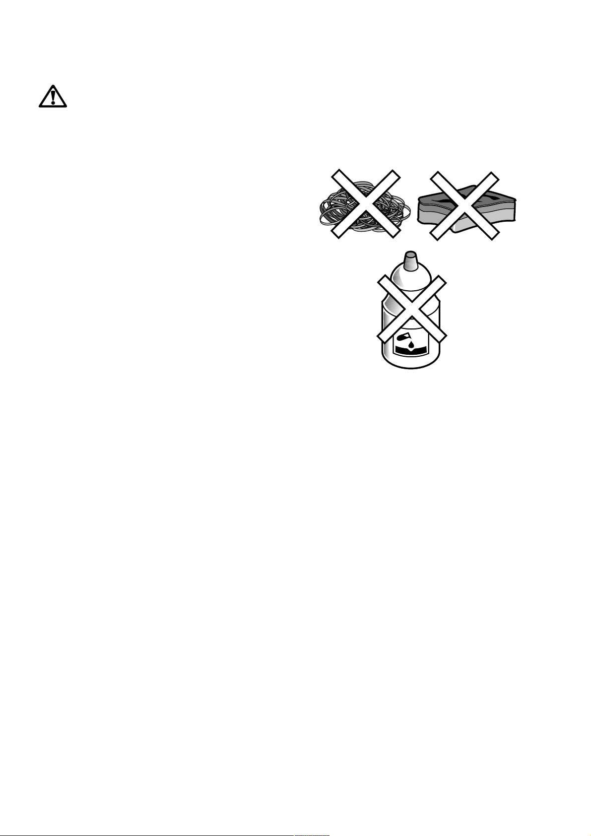
wasing up liquid has been added. Avoid the use
of the following:
- household detergent and bleaches;
- impregnated pads unsuitable for non-stick
saucepans;
- steel wool pads;
- bath/sink stain removers.
Should the hob top become heavily soiled, it is
recommended that a cleaning product such as
Hob Brite or Bar Keepers Friend is used.
Pan Supports
The pan supports are dishwasher proof. If
washing them by hand, take care when drying
them as the enamelling process occasionally
leaves rough edges. If necessary, remove
stubborn stains using a paste cleaner.
The Burners
The burner caps and crowns can be removed for
cleaning.
Wash the burners caps and crowns using hot
soapy water, and remove marks with a mild
paste cleaner. A well moistened soap
impregnated steel wool pad can be used with
caution, if the marks are particularly difficult to
remove.
After cleaning, be sure to wipe dry with a soft
cloth.
13
Page 14
Cleaning the Oven
The oven should be kept clean at all
times. A build-up of fats or other
foodstuffs could result in a fire,
especially in the grill pan.
Cleaning materials
Before using any cleaning materials on your
oven, check that they are suitable and that their
use is recommended by the manufacturer.
Cleaners that contain bleach should NOT be
used as they may dull the surface finishes.
Harsh abrasives should also be avoided.
External cleaning
Regularly wipe over the control panel, oven door
and door seal using a soft cloth well wrung out in
warm water to which a little washing up liquid
has been added.
To prevent damaging or weakening the door
glass panels avoid the use of the following:
Household detergent and bleaches
Impregnated pads unsuitable for
non-stick saucepans
Brillo/Ajax pads or steel wool pads
Chemical oven pads or aerosols
Rust removers
Bath/Sink stain removers
Oven Cavity
The enamelled oven cavity is best cleaned whilst
the oven is still warm.
Wipe the oven over with a soft cloth soaked in
warm soapy water after each use. From time to
time it will be necessary to do a more thorough
cleaning, using a proprietary oven cleaner.
Oven lamp replacement
Disconnect the appliance.
Unscrew the lamp and substitute it with another
suitable for higher temperature (300°C) having
the following characteristics:
Voltage: 230-240V (50Hz)
Power: 15W
Connection: E14
Clean the outer and inner door glass using warm
soapy water. Should the inner door glass
become heavily soiled it is recommended that a
cleaning product such as Hob Brite, or Bar
Keepers Friend is used.
DO NOT clean the oven door while the
glass panels are warm. If this
precaution is not observed the glass
panel may shatter.
If the door glass panel becomes
chipped or has deep scratches, the
glass will be weakened and must be
replaced to prevent the possibility of the
panel shattering. Contact your local
Service Centre who will be pleased to
advise further.
Oven Shelves
To clean the oven shelves, soak in warm soapy
water and remove stubborn marks with a well
wetted soap impregnated pad. Rinse well and
dry with a soft cloth.
FO 0424
Lid cleaning (EK 5701 W/GR
only)
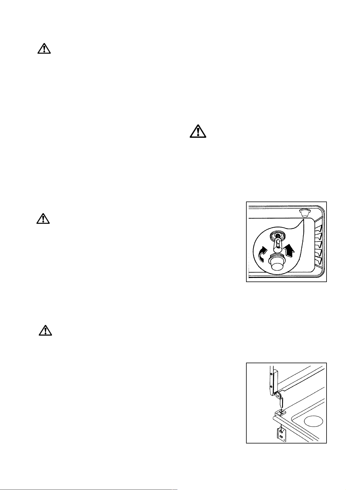
The cooker lid can be disassembled, to allow a
better cleaning(see fig.). After a proper cleaning,
carefully reposition the lid into its hinges.
FO 0418
14
Page 15
Cleaning around the flame spreader
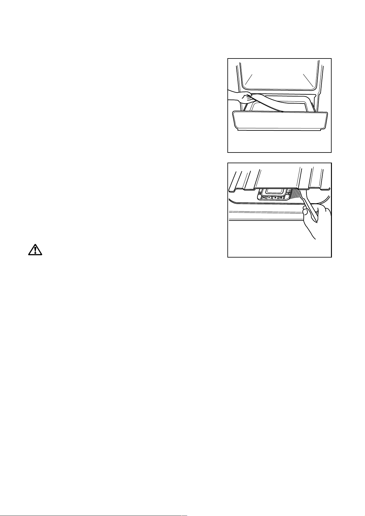
- Remove the small flap.
F
- Slide forward the remainder of the lid.
- Lift from the back.
When cleaning around the flame spreader,
particles can fall into the drawer below. We
recommend placing some paper over the
contents of the drawer whilst cleaning.
Please ensure the paper is removed after
cleaning or it may ignite.
We advise using a stiff dry brush to remove
stubborn grease deposits around the base of the
unit (see Fig.).
Remove any remaining surface fat with a sponge
while the oven is still warm.
Place a brush or other suitable cleaning
implement into the aperture and brush around
the base of the unit with a suitable detergent.
FO 0176
UNDER NO CIRCUMSTANCES
SHOULD THE FLAME SPREADER BE
REMOVED.
After cleaning, replace the lid correctly.
FO 0177
15
Page 16
Something Not Working
If the appliance is not working correctly, please carry out the following checks, before contacting your
local Electrolux Service Centre.
IMPORTANT:
or installation, a charge will be made even if the appliance is under guarantee.
If you call out an engineer to a fault listed below, or to repair a fault caused by incorrect use
symptom
n There is no spark when lighting the gas
n The gas ring burns unevenly
n The oven does not come on
n The oven light does not come on
solution
u Check that the unit is plugged in and the
electrical supply is switched on
u Check that the RCCB has not tripped (if fitted)
u Check the mains fuse has not blown
u Check the burner cap and crown have been
replaced correctly, e.g. after cleaning.
u Check the main jet is not blocked and the
burner crown is clear of food particles.
u Check the burner cap and crown have been
replaced correctly, e.g. after cleaning.
u Check a cooking function / temperature have
been selected.
u Check the socket switch or the switch from
the mains supply to the oven is ON.
u Check the light bulb, and replace it if
necessary (see "Oven Lamp Replacement")
n It takes too long to finish the dishes, or they
are cooked too fast.
n Steam and condensation settle on the food
and the oven cavity.
If after these checks, the appliance still does not
work, contact your local Service Force Centre.
When you contact the Service Centre, they will
need the following information:
1. Your name, address and post code.
2. Your telephone number
3. Clear and concise details of the fault
4. The model and the serial number (see rating
label)
5. Date of purchase
u The temperature may need adjusting
u Refer to the contents of this booklet,
especially to the chapter Using the Oven.
u Leave dishes inside the oven no longer than
15-20 minutes after the cooking is completed.
16
Page 17

Service and Spare Parts
If you require spare parts or an engineer contact
your local Service Force Centre by telephoning:
08705 929 929
Your call will be routed to the Service Centre
covering your post code area. The addresses of
Electrolux Service Force Centres are detailed on
the following pages.
Guarantee Conditions
ELECTROLUX STANDARD GUARANTEE
CONDITIONS
We, Electrolux, undertake that if, within 12 months of
the date of the purchase, this Electrolux appliance or
any part thereof is proved to be defective by any
reason only of faulty workmanship or materials, we
will, at our option, repair or replace the same FREE
OF ANY CHARGE for labour, materials or carriage on
condition that:
* The appliance has been correctly installed and
used only on the gas and electricity supply stated
on the rating plate.
* The appliance has been used for normal domestic
purposes only, and in accordance with the
manufacturer's instructions.
* The appliance has not been serviced, maintained,
repaired, taken apart or tampered with by any
person not authorised by us.
* All service work under this guarantee must be
undertaken by a Electrolux Service Force Centre.
* Any appliance or defective part replaced shall
become the Company's property.
* This guarantee is in addition to your statutory and
other legal rights.
Home visits are made between 8.30am and 5.30pm
Monday to Friday. Visits may be available outside
these hours, in which case a premium will be
charged.
Exclusions
This guarantee does not cover:
* Damage or calls resulting from transportation,
improper use or neglect, the replacement of any
light bulbs or removable parts of glass or plastic.
* Costs incurred for calls to put right an appliance
which is improperly installed or calls to appliance
outside the United Kingdom.
* Appliances found to be in use within a commercial
or similar environment, plus those which are the
subject to rental agreements.
* Products of Electrolux manufacture which are not
marketed by Electrolux.
CUSTOMER CARE
For general enquiries concerning your Electrolux
appliance and for further information on
Electrolux products, contact our Customer Care
Department by letter or telephone as follows:
Customer Care Department
Electrolux
55-77 High Street
Slough
Berkshire SL1 1DZ
Tel : 08705 950 950
European Guarantee
If you should move to another country within Europe
then your guarantee moves with you to your new home
subject to the following qualifications:
* The guarantee starts from the date you first
purchased your product.
* The guarantee is for the same period and to the
same extent for labour and parts as exist in the
new contry of use for this brand or range of
products.
* This guarantee relates to you and cannot be
transferred to another user.
* Your new home is within the European Community
(EC) or European Free Trade Area.
* The product is installed and used in accordance
with our instructions and is only used domestically,
i.e. a normal household
The electrical supply complies with the
specification given in the rating label.
* The product is installed taking into account
regulations in your new country.
Before you move, please contact your nearest
Customer Care centre, listed below, to give them
details of your new home. They will then ensure that
the local Service Organisation is aware of your move
and able to look after you and your appliances.
France Senlis +33 (0)3 44 62 22 22
Germany Nürnberg +49 (0)911 323 2600
Italy Pordenone +39 (0)1678 47053
Sweden Stockholm +46 (0)20 78 77 50
UK Slough +44 (0)1753 219 898
17
Page 18
ELECTROLUX SERVICE FORCE
To contact your local Electrolux Service Force Centre telephone 08705 929 929
CHANNEL ISLANDS
GUERNSEY Guernsey Electricity
PO Box 4
Vale, Guernsey
Channel Islands
JERSEY Jersey Electricity
Company
PO Box 45
Queens Road
St Helier
Jersey
Channel Islands
JE4 8NY
SCOTLAND
ABERDEEN 54 Cl aremont Street
(M05) Aberdeen
AB10 6RA
AUCHTERMUCHY 33A Burnside
(M03) Auchtermuchy
Fife
KY14 7AJ
BLANTYRE Unit 5
(M07) Block 2
Auchenraith Industrial
Estate
Rosendale Way
Blantyre
G72 0NJ
DUMFRIES 9 3 Irish Street
(M01) Dumfries
Scotland
DG1 2PQ
DUNOON Briar Hill
7 Hill Street
(M 67) Dunoon
Argyll
PA23 7AL
GLASGOW 20 Cunningham Road
(M04) Clyde Estate
Rutherglen,
Glasgow,
G73 1PP
INVERNESS Unit 3B
(M06) Smithton Indust. Est.
Smithton
Inverness
IV1 2PD
ISLE OF ARRAN Arran Domestics
(OWN SALES) Unit 4 The Douglas
Centre
Brodick
Isle of Arran
KA27 8AJ
ISLE OF BARRA J Zerfah
(OWN SALES) 244 Bruernish
Isle of Barra
Western Islands
HS9 5QY
ISLE OF BUTE Walker Engineering
(M66) Glenmhor
Upper Serpentine
Road
Rothesay
Isle of Bute
PA20 9EH
ISLE OF LEWIS ND Macleod
(M69) 16 James Street
Stornoway
Isle of Lewis
PA872QW
KELSO 2-8 Wood Market
(M08) Kelso
Borders TD5 7AX
ORKNEY Corsie Domestics
(M65) 7 King Street
Kirkwall
Orkney KW15 1RE
PERTH Hydro Electrical
Inveralmond House
Ruthervenfield Road
Perth PH1 3AQ
PERTH Graham Begg Unit 4
(OWN SALES) Airport Ind Estate
Wick KW1 4QS
SHETLAND Tait Electronic
(OWN SALES) Systems Ltd.
Holmsgarth Road
Lerwick
Shetland ZE1 0PW
SHETLAND Bolts Shetland Ltd
(OWN SALES) 26 North Road
Lerwick
Shetland ZE1 0PE
WHALSAY Leask Electrical
Harlsdale
Symbister, Whalsay
(OWN SALES) Shetland ZE2 9AA
NORTHERN IRELAND
BELFAST Owenm ore House
(M27) Kilwee Industrial
Estate
Upper Dunmury Lane
Belfast
BT17 0HD
WALES
CARDIFF Guardian Industrial
(M28) Estate
Clydesmuir Road
Tremorfa, Cardiff
CF2 2QS
CLYWD Unit 6-7 Coed - Parc
(M14) Abergele Road
Rhuddlan
Clwyd
Wales
LL18 5UG
OSWESTRY Plas Funnon
Warehouse
(M17) Middleton Road
Oswestry
SY11 2PP
HAVERFORDWEST Cr omlech Lodge
(M75) Ambleston
Haverfordwest
Pembrokeshire
SA62 5DS
DYFED Maes Y Coed
(M77) High Mead
Llanybydder
Carmarthenshire
SA40 9UL
NORTH EAST
GATESHEAD Unit 356a
(M39) Dukesway Court
Dukesway
Team Valley
Gateshead
NE11 0BH
GRIMSBY 15 Hai nton Avenue
(M42) Grimsby
South Humberside
DN32 9AS
HULL Unit 1
(M41) Boulevard Industrial
Estate
Hull
HU3 4AY
LEEDS 64- 66 Cr oss Gates
(M37) Road
Leeds
LS15 7NN
NEWTON AYCLIFFE Unit 16
(M45) Gurney Way
Aycliffe Ind Estate
Newton Aycliffe
DL5 6UJ
SHEFFIELD Pennine House
(M38) Roman Ridge Ind.
Roman Ridge Road
Sheffield
S9 1GB
NORTH WEST
BIRKENHEAD 1 Kelvin Park
(M11) Dock Road
Birkenhead
L41 1LT
CARLISLE Unit 7
(M10) James Street
Workshops
James Street
Carlisle
Cumbria CA2 5AH
ISLE OF MAN South Quay Ind.
(M64) Estate
Douglas
Isle of Man IM1 5AT
LIVERPOOL Unit 1
(M15) Honeys Green
Precinct
Honeys Green Lane
Liverpool
L12 9JH
MANCHESTER Unit B
(M09) Central Industrial
Estate
St Marks Street
Bolton
BL3 6NR
PRESTON Un it 250
(M13) Dawson Place
Walton Summit
Bamber Bridge
Preston
Lancashire
PR5 8AL
STOCKPORT Unit 20 Haigh Park
(M16) Haigh Avenue
Stockport
SK4 1QR
18
Page 19
ELECTROLUX SERVICE FORCE
To contact your local Electrolux Service Force Centre telephone 08705 929 929
MIDLANDS
BIRMINGHAM 66 B ir ch Road East,
(M18) Wyrley Road
Industrial
Estate
Witton
Birmingham
B67DB
BOURNE M anning Road Ind
(M44) Estate
Pinfold Road
Bourne
PE10 9HT
BRIDGNORTH 65 St.M ary s Street
(M72) Bridgnorth
Shropshire
WV16 4DR
GLOUCESTER 101 Rycroft Street
(M23) Gloucester
GL1 4NB
HEREFORD Unit 3
(M31) Bank Buildings
Cattle Market
Hereford
HE4 9HX
HIGHAM FERRERS 30 High Street
(M51) Higham Ferrers
Northants
NN10 8BB
ILKESTON Unit 2
(M43) Furnace Road
Ilkeston
DE7 5EP
LEICESTER Unit 7
(M22) Oaks Industrial Estate
Coventry Road
Narborough
Leicestershire
LE0 5GF
LINCOLN Uni t 8 Stonefield Park
(M40) Clifton Street
Lincoln
LN5 8AA
NEWCASTLE 18 -2 1 Croft Ro ad
UNDER LYME Br ampton Industrial
(M12) Estate
Newcastle under
Lyme
Staffordshire
ST5 0TW
REDDITCH 13 Thornhill Road
(M20) North Moons Moat
Redditch
Worcestershire
B98 9ND
TAMWORTH Unit 3
(M19) Sterling Park
Claymore
Tamworth
B77 5DO
WORCESTER Un it 1&2
(M73) Northbrook Close
Gregorys Mill Ind
Estate
Worcester
WR3 8BP
LONDON & EAST ANGLIA
BECKENHAM 11a Gardener Ind
(M79) Estate
CHELMSFORD Hanbury Road
(M47) Widford Ind Estate
COLINDALE Unit 14
(M53) Capital Park
ELTHAM 194 Court Road
(M78) Mottingham - Eltham
ENFIELD 284 Alma Road
(M49) Enfield
GRAVESEND Un it B4,
(M57)
HARPENDEN Unit 4
(M46) Riverside Estate
LETCHWORTH 16 -17 Woodsite Ind
(M50) Est.
LONDON 2/4 Roya l Lane
(M76) Yiewsley
MAIDENHEAD Reform Road
(M60) Maidenhead -
MOLESEY 10 Island Farm
(M61) Avenue
NEWBURY 9 Pipers Court
(M24) Berkshire Drive
IPSWICH Unit 6C
(M48) Elton Park Business
NORWICH 2b Trafalgar Street
(M52) Norwich
SUNBURY Uni t 1a
(M63) The Summit
Kent House Lane
Beckenham
Kent BR3 1QZ
Chelmsford
Essex
CM12 3AE
Capital Way
Colindale
London NW9 0EQ
London SE9 4EW
London
EN3 7BB
Imperial Business
Estate
Gravesend
Kent
DA11 0DL
Coldharbour Lane
Harpenden
AL5 4UN
Works Road
Letchworth
Herts
SG6 1LA
West Drayton
Middlesex
UB7 8DL
Berkshire
SL6 8BY
West Molesey
Surrey
KT8 2UZ
Thatcham
Berkshire
RG19 4ER
Centre
Hadleigh Road
Ipswich
IP2 0DD
NR1 3HN
Hanworth Road
Hanworth Ind Estate
Sunbury on Thames
TW16 5D
SOUTH EAST
ASHFORD Unit 2
(M58) Bridge Road
FLEET Unit 1
(M59) Redfields Industrial
HAYWARDS HEATH 21-25 Bridge Road
(M55) Haywards Heath
Business
Estate
Bridge Road
Ashford
Kent
TN2 1BB
Estate
Church Crookham
Fleet
Hampshire
GU13 0RD
Sussex
RH16 1UA
SOUTH WEST
BARNSTAPLE Main Road
(M30) Fremington
BOURNEMOUTH 63-65 Curzon Road
(M26) Bournemouth
BRIDGEWATER
(M35)
BRISTOL 11 Eldon Way
(M25) Eldonwall Trading
EMSWORTH 266 Main Road
(M33) Southboure
ISLE OF WIGHT Unit 8
(M34) Enterprise Court
NEWTON ABBOT Unit 2
(M29)
PLYMOUTH 16 Faraday Mill
(M32) Cattledown
REDRUTH Unit 7D Pool Industrial
(M36) Estate
Barnstaple
North Devon
EX31 2NT
Dorset
BH1 4PW
6 Hamp Industrial
Estate
Bridgewater
Somerset
Bristol
Avon
BS4 3QQ
Emsworth
PO10 8JL
Ryde Business Park
Ryde
Isle of Wight
PO33 1DB
Zealley Industrial
Estate
Kingsteignton
Newton Abbot
S. Devon
TQ12 3TD
Plymouth
PL4 0ST
Wilson Way, Redruth,
Cornwall
TR15 3QW
19
Page 20

Instructions for the Installer
Technical Data
Model Number: EK 5701
Appliance Class 2 sub class 1 and Class 1
Appliance category
APPLIANCE GAS SUPPLY: Natural gas G20 20mbar
: II 2H3+
Dimensions
Height 900 mm
Depth 600 mm
Width 497 mm
Oven Capacity 1.7 Cu. ft
Hob
Rear left burner (rapid) 3,000 W
Front left burner (semi-rapid) 2,000 W
Rear right burner (semi-rapid) 2,000 W
Front right burner (auxiliary) 1,000 W
TYPE OF
GAS
BURNER RAPID SEMI-RAPID AUXILIARY OVEN
CHARACTERISTICS
3
3
POSITION MAX MIN MAX MIN MAX MIN MAX MIN
NOMINAL THERMAL
POWER kW 3.0 0.65 2.0 0.45 1.0 0.33 3.0 1.0
(large) (medium) (small)
Oven
Gas Grill 2,100 W
Oven burner 3,000 W
Oven light 15 W
Supply voltage (50 Hz) 230-240 V
Total cooker rating 11,000 W
GRILL
2.1
20
20 mbar
NATURAL GAS
LPG GAS
28-30/37 mbar
NOMINAL FLOW
RATE m3/h 0.286 0.057 0.190 0.038 0.095 0.028 0.286 0.095
Ws - 50.7 MJ/ m
NOZZLE REFERENCE 11 9 Adjust. 9 6 Adjust. 7 0 Adjust. 116 Adjust.
VALUE = 37.78 MJ/m
VALUE = 49.92 MJ/Kg
1/100 mm
NOMINAL THERMAL
POWER kW 2.8 0.65 2.0 0.45 1.0 0.33 3.0 1.0
NOMINAL FLOW
RATE g/h 20 2 43.5 144 29 72 21,5 216 72
NOZZLE REFERENCE 8 6 4 0 71 3 2 5 0 2 8 8 2 5 2
1/100 mm
0.199
99
2.1
153
71
Page 21

Important Safety Requirements
This appliance must be installed in accordance
with the Gas Safety (Installation and Use)
Regulations (current addition) and the I.E.E.
Wiring Regulations. Detailed recommendations
are contained in the following British Standard
Codes of Practice - B.S. 6172, B.S. 5440: Part 2
and B.S. 6891: Current Editions.
Provision for Ventilation
The room containing the cooker should have an
air supply in accordance with B.S. 5440: Part 2:
Current Editions.
The following requirements for ventilation must
be met.
Positioning the Cooker
Caution:
Some soft or badly fitted floor coverings can be
damaged when the cooker is moved across
their surface for cleaning. It is advisable to
ensure that the floor covering in the area below
the cooker is either securely fixed so as not to
ruck up when the cooker is moved or, if
preferred, removed.
The cooker should not be installed in a bed
sitting room with a volume of less than 20m
is installed in a room of volume less 5m
vent of effective area of 110cm2 is required; if it
is installed in a room of volume between 5m
and 10m3, an air vent of effective area 50cm2 is
required, while if the volume exceeds 11m3 no
air vent is required. However, if the room has a
door which opens directly to the outside, no air
vent is required even when the volume is
between 5m
If there are other fuel burning appliances in the
same room, B.S. 5440: Part. 2: Current Editions
should be consulted to determine the requisite
air vent requirements.
3
and 11m3.
3
an air
3
, if it
3
Location
The cooker may be located in a kitchen, a
kitchen/diner or bedsitting room but not in a
bathroom, shower room or garage.
For information regarding the fitting of flexible
supply pipes, the highest temperature at the rear
of this cooker which may come into contact with
the supply pipe is 70°C above ambient.
When the appliance has been installed there
must be enough space fot the hotplate lid (when
present) to open fully.
21
Page 22
Installation
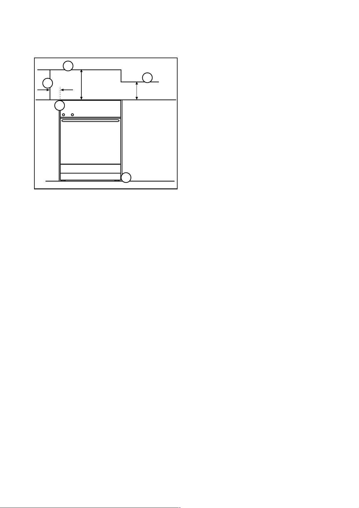
D
E
C
115
780
420
B
A
FO 1141
Dimensions are given in millimeters
The appliance must be installed in accordance
to the type X (standard EN 60335-2-6).
Therefore the appliance can not be installed
beside furniture higher than the cooker worktop.
Fig. 1
1. Positioning the Appliance
(Fig. 1)
Note A:
The appliance is designed to be flush fitted with
2mm clearance at each side to allow for it to be
pulled forward for cleaning etc.
Note B:
The hotplate side trims should be flush with the
cabinets and must not be below. Adjustable
levelling feet at the front and rear are provided on
the base of the appliance. Adjustment is
obtained by rotating in or out, the feet at the front
or rear of the appliance from the underside of
the appliance, with the drawer removed.
A spirit level should be placed on a cake tray on
one of the shelves to confirm that the appliance
is correctly levelled.
The levelling feet fitted to the appliance will
achieve a height to hotplate trims of 900mm-0 +
10.
Note C:
This cooker must only be installed by qualified
personnel, according to the manufacturers
instructions and to the relevant British
Standards.
If the appliance is fitted next to a side wall or
cabinets above height of the hotplate trims, then
a gap of 115 mm is required.
Curtains must not be fitted immediately behind
the cooker or within 115 mm of the sides of the
cooker.
Note D:
Any wall cabinet or extractor must not be lower
than 780mm above hotplate level.
Note E:
Wall cabinets may be fitted in line with the sides
of the base units, providing that the lower edge
of the wall cabinet is a minimum of 420mm
above the worktop.
22
Page 23
WALL FACE
300 mm.
BACK OF COOKER
480 mm.
100 mm.
PENCIL LINE ON THE FLOOR
245 mm.
250 mm.
FO 2434
PLAN VIEW OF THE COOKER
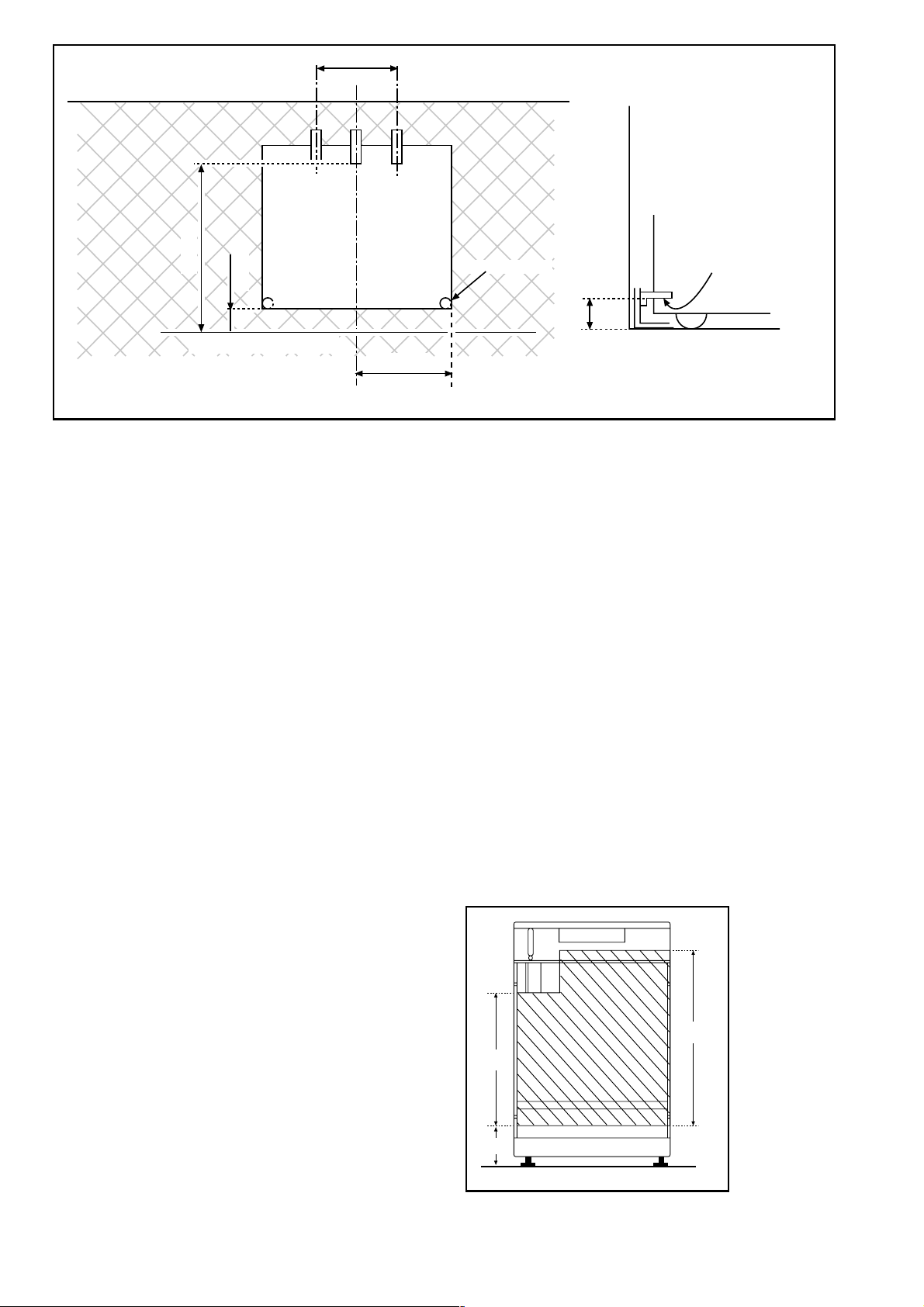
Fig. 2
Fitting the Stability Bracket
(Not supplied)
If the cooker has to be installed with a flexible
supply pipe, it is necessary that a stability device
is fitted.
(See safety Requirements: Page 22).
If a stability bracket is to be fitted by the installer,
these instructions should be read in conjunction
with the leaflet packed with the stability bracket.
Place cooker in its intended position and level
cooker.
Mark off 250 mm (11
side of the cooker as shown, this is the centre
line of the bracket fixing.
1
/2") from the right hand
ENGAGEMENT EDGE FOR
LEVELLING FEET
A
STABILITY BRACKET
BASE OF COOKER
SIDE VIEW
OF THE COOKER
Dimensions are given in millimeters
Connecting to Gas
This cooker is designed to be installed with an
appliance flexible connection. Connection is
made to the RC 1/2 (1/2" B.S.P.) threaded entry
pipe located just below the hotplate level on the
rear right-hand side of the cooker. Check for gas
soundness after connecting the gas supply.
The gas bayonet connector must be fitted in the
shaded area indicated in the diagram. Take into
account that it must be possible to pull the
cooker forward sufficiently. The hose must not
get caught on the stability bracket.
Note:
For certain types of gas bayonet connection
used, it may not be possible for the appliance to
be pushed fully back to the wall stops.
Draw a line 100mm (4") from the front edge of
the levelling feet (see Fig. 2) and remove cooker
from its position. Mark off 480mm (19") back
from this line on the centre line of the bracket to
locate the front edge of the lower bracket.
Fix lower bracket (with two fixing holes) to the
floor, then measure height from floor level to
engagement edge on back of cooker, dimension
'A' of Fig. 2.
Assemble upper bracket to lower bracket so that
underside of bracket is dimension 'A' +3mm (1/
8") above floor level. Re-position cooker and
check that top bracket engages into cooker back
to a depth of 75mm (3"), as shown in Fig. 2.
Should the stability bracket currently installed not
allow the cooker to stand correctly, ask the
installer to replace it with the correct type.
Important:
Flexible tubing MUST comply with BS.669
Current Edition.
600
450
130
FO 2435
Fig. 3
Dimensions are given in millimeters
23
Page 24
Electrical connections
Any electrical work required to install
this cooker should be carried out by a
qualified electrician or competent
person, in accordance with the current
regulations.
THIS COOKER MUST BE EARTHED.
The manufacturer declines any liability
should these safety measures not be
observed.
This cooker is designed to be connected to
a 230-240V 50Hz AC electrical supply.
Before switching on, make sure the electricity
supply voltage is the same as that indicated on
the cooker rating plate. The rating plate is located
on the oven frame.
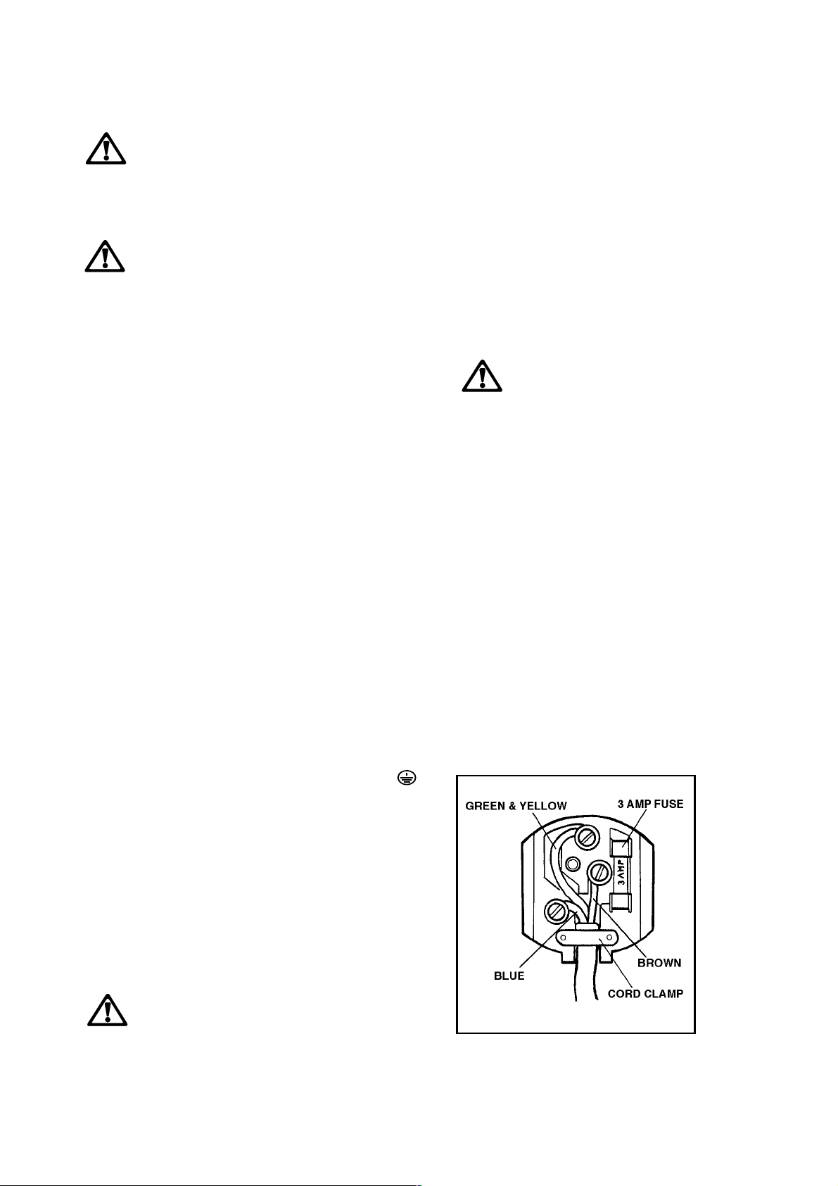
The cooker is supplied with a 3 core flexible
supply cord incorporating a 3amp plug fitted. In
the event of having to change the fuse, a 3amp
ASTA approved (BS 1362) fuse must be used.
Should the plug need to be replaced for any
reason, the wires in the mains lead are coloured
in accordance with the following code:
Permanent Connection
In the case of a permanent connection, it is
necessary that you install a double pole switch
between the cooker and the electricity supply
(mains), with a minimum gap of 3 mm. between
the switch contacts and of a type suitable for the
required load in compliance with the current
electric regulations.
The switch must not break the yellow and green
earth cable at any point.
Ensure that the cooker supply cord
does not come into contact with
surfaces with temperatures higher than
50 deg. C.
Green and Yellow- Earth
Blue - Neutral
Brown - Live
Connect the green and yellow (earth) wire
F
Upon completion there must be no cut, or stray
strands of wire present and the cord clamp must
be secure over the outer sheath.
to the terminal in the plug which is marked
with the letter 'E' or the earth symbol
or coloured green and yellow.
Connect the blue (neutral) wire to the
terminal in the plug which is marked with
the letter 'N' or coloured black.
Connect the brown (live) wire to the
terminal in the plug which is marked with
the letter 'L' or coloured red.
A cut off plug inserted into a 13 amp
socket is a serious safety (shock)
hazard. Ensure that the cut off plug is
disposed of safely.
FO 0390
24
Page 25
Commissioning
When the cooker has been fully installed it will be
necessary to check the minimum flame setting.
To do this, follow the procedure below.
- Turn the gas tap to the MAX position and ignite.
- Set the gas tap to the MIN flame position then
turn the control knob from MIN to MAX several
times. If the flame is unstable or is extinguished
follow the procedure below.
Procedure:
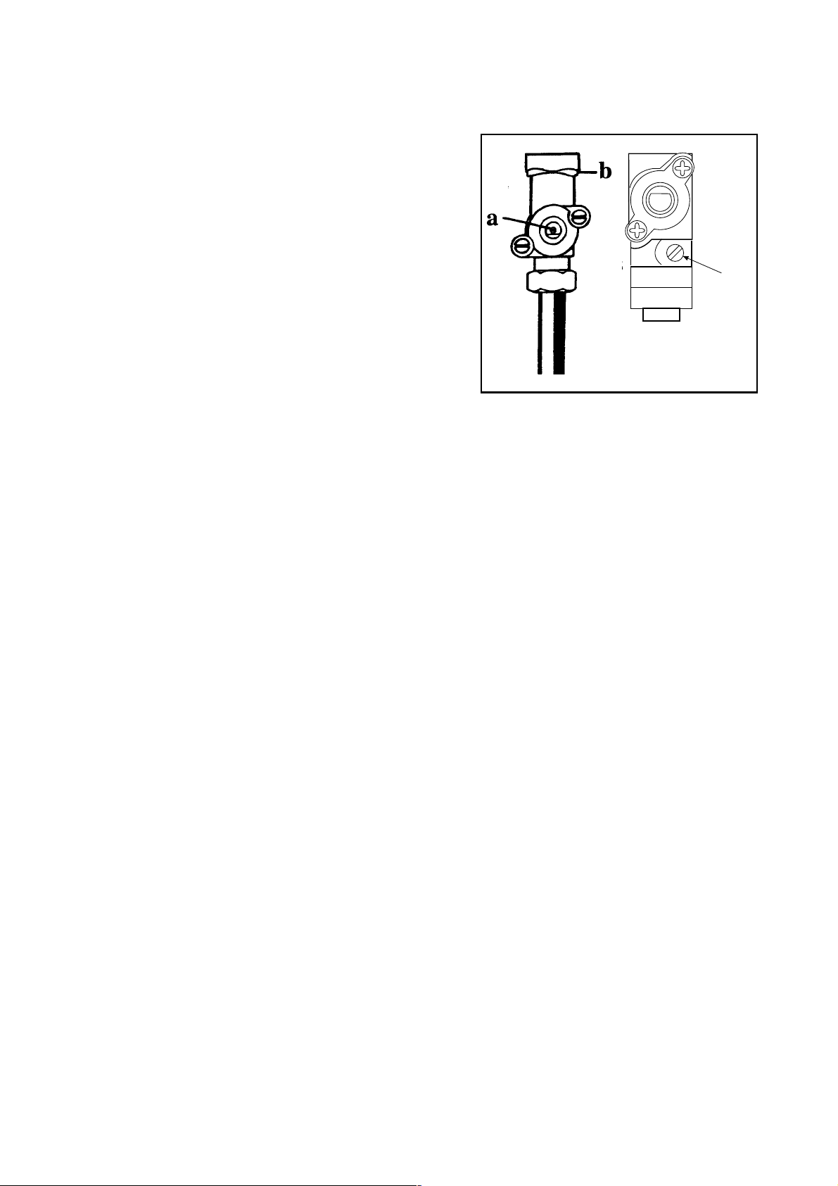
a
F
Pressure Testing
F
Re-ignite the burner and set to MIN.
Remove the control knob.
The adjustment screw is located down
the centre of the gas tap control shaft or
on the lower right hand side of the shaft
(see diagram).
To adjust, use a thin bladed screwdriver
and turn the adjustment screw until the
flame is steady and does not extinguish,
when the knob is turned from MIN to
MAX. Repeat this procedure for all
burners.
Remove pan support and front left
burner cap and crown.
Fit manometer tube over the injector.
Turn on the burner gas supply and ignite
another burner supply.
FO 1032
a) Minimum adjustment screw
b) Tap
The pressure reading should be
nominally 20mbar and must be between
17 mbar and 25mbar.
Turn off the burner supplies.
25
Page 26
Conversion from Natural to LPG
Gas
IMPORTANT
The replacement/conversion of the gas cooker
should only be undertaken by a CORGI
registered engineer.
It is important to note that this model is designed
for use with natural gas but can be converted for
use with butane or propane gas providing the
correct injectors are fitted. The gas rate is
adjusted to suit.
Method
Ensure that the gas taps are in the 'OFF' position
Isolate the hob from the electricity supply
Remove all pan supports, burner caps, rings,
crowns and control knobs.
With the aid of a 7mm box spanner the burner
injectors can then be unscrewed and replaced
by the appropriate LPG injectors (see Table at
page 20).
TO ADJUST THE GAS RATE
With the aid of a thin bladed screwdriver
completely tighten clockwise the by pass screw.
Upon completion stick the replacement rating
plate near the gas supply pipe.
Replacement of gas oven
burner nozzle
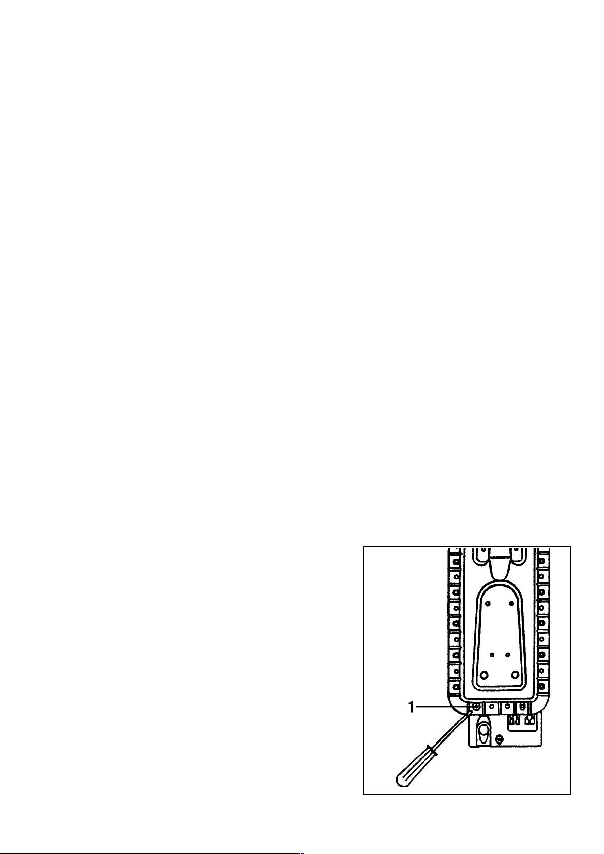
To replace the gas oven nozzle, follow this procedure:
a) remove the bottom of the oven;
b) undo screw 1 and take the oven burner out;
c) with a socket spanner 7 unscrew and remove
the nozzle, situated in the bottom of the oven,
and replace it with the proper one (see Table at
page 20);
d) reassemble the burner following the same pro-
cedure backwards.
26
FO 1072
Page 27
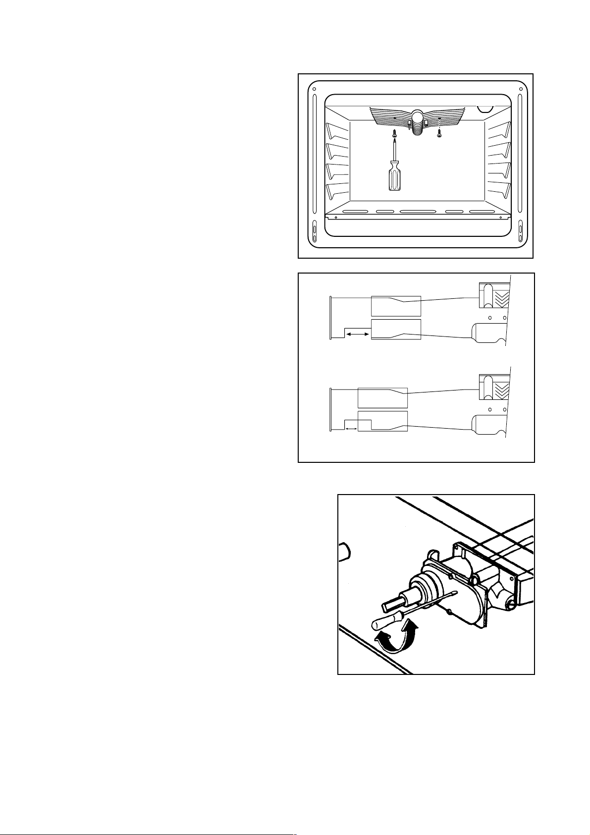
Replacement of grill burner
nozzle
To replace the grill burner nozzle, follow this
procedure:
a) remove the screws (see fig.);
b) take the grill burner out;
c) with a socket spanner 7 unscrew and remove
the nozzle, situated in the top of the oven, and
replace it with the proper one (see Table at page
21);
d) undo the fixing screw of the metal ring of primary
air adjustment and adjust the relevant opening
(see diagram);
e) reassemble the burner following the same pro-
cedure backwards.
Natural gas adjustment: full opening width
Minimum level adjustment
of gas oven burner
After setting the oven on maximum temperature
with door closed for about 10 minutes, turn the
knob on minimum.
To reach the thermostat by-pass screw and
adjust the minimum level, act as follows:
take out the knobs;
remove the front panel;
in case of conversion from natural gas to LPG,
tightly screw the by-pass screw of thermostat
(see fig.);
to convert from LPG to natural gas, unscrew
the by-pass screw, until a regular small flame
is reached.
finally check that turning quickly the tap from
maximum position to minimum position, the
flame does not go out;
reassemble the front panel and the knobs.
The oven burner does not need any primary air
regulation.
LPG adjustment: opening 10 mm wide
FO 1061
27
Page 28

CUSTOMER CARE
Electrolux
55-77 High Street
Slough
Berkshire - SL1 1DZ
Tel : 08705 950950
© Electrolux Household Appliances Limited 2000
The Electrolux Group. The worlds No.1 choice.
The Electrolux Group is the worlds largest producer of powered appliances for kitchen, cleaning and outdoor use. More than
55 Group products (such as refrigerators, cookers, washing machines, vacuum cleaners, chain saws and lawn mowers) are
sold each year to a value of approx. USD 14 billion in more than 150 countries around the world.
28
Grafiche MDM - Forlì
10/00
Page 29

documentation manual, user maintenance, brochure, user reference, pdf manual
This file has been downloaded from:
User Manual and User Guide for many equipments like mobile phones, photo cameras, monther board, monitors, software, tv, dvd, and othes..
Manual users, user manuals, user guide manual, owners manual, instruction manual, manual owner, manual owner's, manual guide,
manual operation, operating manual, user's manual, operating instructions, manual operators, manual operator, manual product,
 Loading...