

Electrolux EIFLS55IMB1, EIFLS55QT0 Installation Guide

EN FRONT LOAD WASHER
FR LAVEUSE Á CHARGEMENT FRONTAL
ES LAVADORA DE CARGA FRONTAL
INSTALLATION INSTRUCTIONS
INSTRUCTIONS D’INSTALLATION
INSTRUCCIONES DE INSTALACIÓN
137381200B October 2013
2
Important Safety Instructions
WARNING
For your safety the information in this manual must be followed to minimize the risk of fi re or explosion
or to prevent property damage, personal injury or loss of life. Do not store or use gasoline or other
fl ammable vapors and liquids in the vicinity of this or any other appliance.
Recognize safety symbols, words and
labels
Safety items throughout this manual are labeled
with a WARNING or CAUTION based on the risk
type as described:
This symbol alerts you to situations that may cause serious body
harm, death or property damage.
This symbol alerts you to situations that may cause bodily injury
or property damage.
WARNING
RISK OF FIRE - Read all of the following instructions before installing and using this appliance:
• Destroy the carton and plastic bags after the dryer is unpacked. Children might use them for play. Cartons
covered with rugs, bedspreads, or plastic sheets can become airtight chambers causing suffocation. Place
all materials in a garbage container or make materials inaccessible to children.
• For your safety the information in this manual must be followed to minimize the risk of fi re or explosion or to prevent property damage, personal injury or loss of life. Do not store or use gasoline or other
fl ammable vapors and liquids in the vicinity of this or any other appliance.
• Install the washer according to the manufacturer’s instructions and local codes.
• The electrical service to the washer must conform with local codes and ordinances and the latest edition of the National Electrical Code, ANSI/NFPA 70, or in Canada, the Canadian electrical code C22.1
part 1.
• To avoid back or other injury, have more than one person move or lift the washer.
• Do not stack a dryer on top of washer already installed on pedestal. Do not stack washer on top of
dryer. Do not stack washer on top of another washer.
• The instructions in this manual and all other literature included with this dryer are not meant to cover
every possible condition and situation that may occur. Good safe practice and caution MUST be ap-
plied when installing, operating and maintaining any appliance.
Save these instructions for future reference.
Table of contents
Important Safety Instructions ......................................... 2
Installation Requirements ............................................3-5
Installed Dimensions ...................................................... 6
©2013 Electrolux Major Appliances
Installation Instructions ............................................. 7-11
Reversing Door ........................................................12-17
Options ......................................................................... 18
All rights reserved.
Installation Requirements
3
Please read and save this guide
Thank you for choosing Electrolux, the new
premium brand in home appliances. These
Installation Instructions are part of our commitment
to customer satisfaction and product quality
throughout the life of your new appliance.
Installation Checklist
Shipping Hardware
Foam shipping support (under wash tub)
removed and stored
Shipping bolts and spacers removed from
rear of appliance and stored
Hole plugs (shipped in bag in drum)
installed in holes in backsheet
Leveling
Washer is level, side-to-side and front-toback
Cabinet is setting solid on all corners
Water Supply
Use only new hoses and verify rubber
sealing washers are installed
HOT supply is connected to HOT inlet and
COLD supply is connected to COLD inlet
HOT and COLD water supply turned on
No leaks present at water supply
connections or appliance inlet connections recheck in 24 hours
Questions?
For toll-free telephone support in the U.S.:
1-877-4ELECTROLUX (1-877-435-3287) and in
Canada: 1-800-265-8352.
For online support and product information visit
www.electroluxappliances.com.
Drain
Stand pipe or wall drain height minimum 24”
Drain hose snapped in “U” channel
(shipped in drum)
Drain hose secured in place with cable tie
(shipped in drum)
Door Reversal
Follow detailed instructions in this guide
Test hinge and latch for function
Electrical Power
House power turned on
Washer plugged in
Final Checks
Installation Instructions and Use and Care
Guide read thoroughly
Door locks and water enters drum when
cycle starts
Registration card sent in
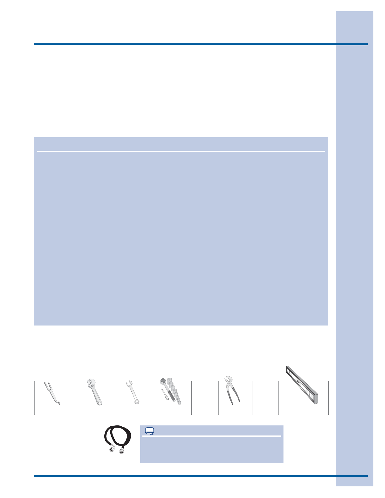
Pre-installation requirements
Tools and materials needed for installation:
OR OR OR AND AND
Optional
universal wrench
Adjustable
wrench
3/8” or 10 mm
box wrench
Ratchet and
socket set
NOTE
Hoses are not included with washer purchase.
Inlet hose (x2)
See “Accessories” section for various inlet hose
kits to fi t your specifi c installation.
Adjustable
pliers
Carpenter’s level
4
Grounding type
ll receptacle
wer cord with
3-prong grgr
ounded plug
Do not,
under
y cir
cumstances,
cut,
removeve,
or b
ypass the
ounding pr
ong.
Installation Requirements
Electrical system requirements
CIRCUIT - Individual, properly polarized and
grounded 15 amp. branch circuit fused with 15
amp. time delay fuse or circuit breaker.
POWER SUPPLY - 2 wire, with ground, 120 volt
single phase, 60 Hz, Alternating Current.
NOTE
Because of potentially inconsistent voltage
capabilities, the use of this washer with power
created by gas powered generators, solar
powered generators, wind powered generators
or any other generator other than the local utility
company is not recommended.
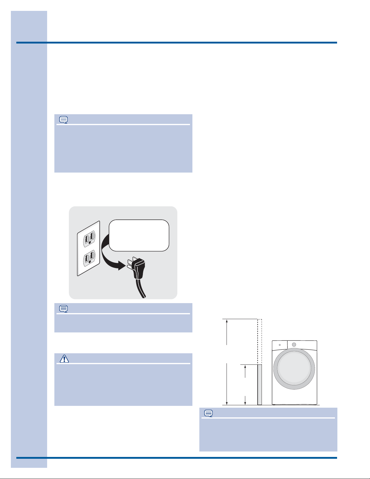
OUTLET RECEPTACLE - Properly grounded
3-prong receptacle to be located so the power
supply cord is accessible when the washer is in
an installed position.
Grounding type
wawall receptacl
Do not,
under
anany cir
cumstances,
cut,
remo
or b
ypass th
PoPower cord with
3-prong
ounded plug
grgrounding pr
ong.
NOTE
GFI (Ground Fault Interrupter) receptacle is not
required.
supply cord having an equipment-grounding
conductor and a grounding plug, the plug
MUST be plugged into an appropriate, copper
wired receptacle that is properly installed and
grounded in accordance with all local codes and
ordinances or in the absence of local codes,
with the National Electrical Codes, ANSI/NFPA
70 (latest edition). If in doubt, call a licensed
electrician. DO NOT cut off or alter the grounding
prong on the power supply cord. In situations
where a two-slot receptacle is present, it is
the owner’s responsibility to have a licensed
electrician replace it with a properly grounded
three prong grounding type receptacle.
Water supply requirements
Hot and cold water faucets MUST be installed
within hose length of your washer’s water inlet. The
faucets MUST be 3/4 inch (1.9 cm) with threading for laundry hose connection. Water pressure
MUST be between 30 and 120 psi. Pressure difference between hot and cold cannot be more than
10 psi. Your water department can advise you of
your water pressure.
Drain system requirements
1. Drain capable of eliminating 17 gals (64.3 L) per
minute.
2. A standpipe diameter of 1-1/4 in. (3.18 cm)
minimum.
3. The standpipe height above the fl oor should be:
Minimum height: 24 in. (61 cm)
Maximum height: 96 in. (244 cm)
Grounding requirements
WARNING
ELECTRICAL SHOCK HAZARD
Improper connection of the equipment grounding
conductor can result in a risk of electrical shock.
Check with a licensed electrician if you are in doubt
as to whether the appliance is properly grounded.
1. The washer MUST be grounded. In the event
2. Since your washer is equipped with a power
of malfunction or breakdown, grounding will
reduce the risk of electrical shock by a path of
least resistance for electrical current.
96”
(244cm)
max.
24”
(61cm)
min.
NOTE
Drain hose attached to the washer can reach a 79
in. (201 cm) high standpipe. For higher standpipe,
use hose P/N 137098000, available from an
authorized parts distributor.
Clearance requirements
Installation Requirements
5
IMPORTANT
DO NOT INSTALL YOUR WASHER:
1. In an area exposed to dripping water or outside weather conditions. The ambient temperature should never be below 60° F (15.6° C) to
maximize detergent effectiveness.
2. In an area (garage or garage-type building)
where gasoline or other fl ammables (including
automobiles) are kept or stored.
3. On carpet. Floor MUST be solid with a maximum slope of 1 inch (2.54 cm). To minimize
vibration or movement, reinforcement of the
fl oor may be necessary.
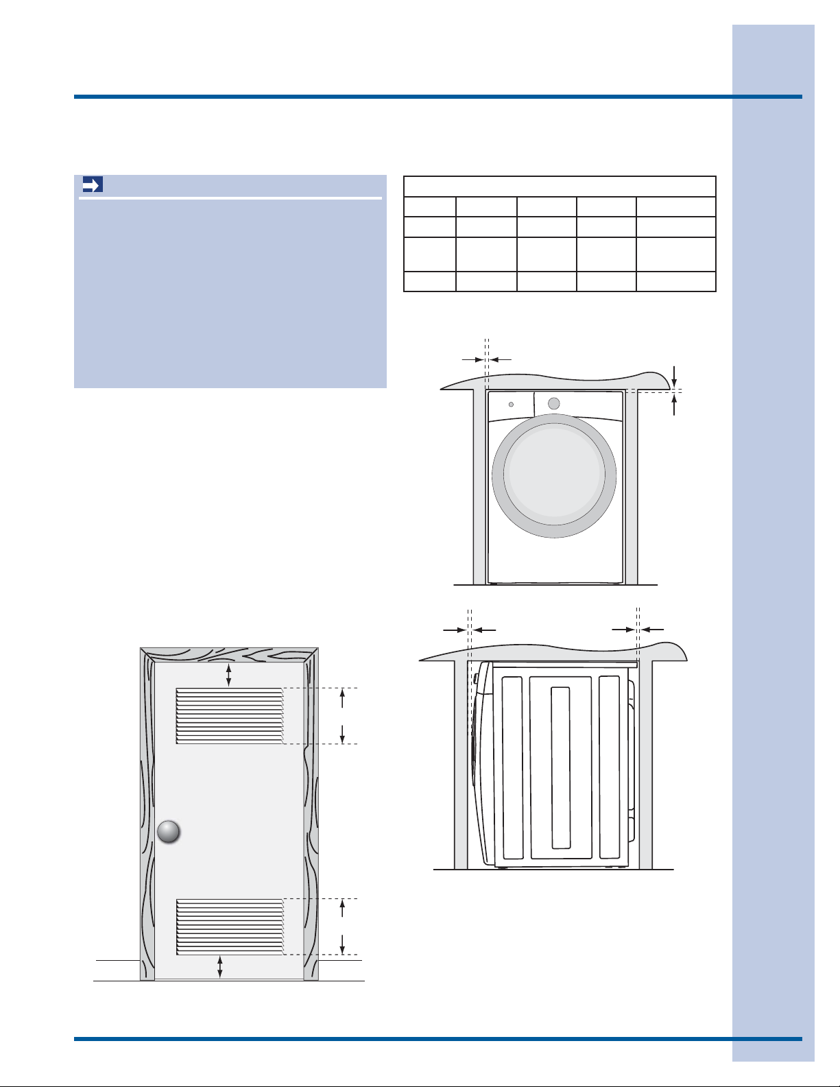
INSTALLATION IN A RECESS OR CLOSET
If washer and dryer are installed in the same
closet, door ventilation is required: A minimum of
120 square inches (774.2 cm²) of opening, equally
divided at the top and bottom of the door, is
required. Louvered openings should be located 3
inches (7.6 cm) from bottom and top of door. Air
openings are required to be unobstructed when a
door is installed. A louvered door with equivalent
air openings for the full length of the door is
acceptable.
MINIMUM INSTALLATION CLEARANCES - Inches (cm)
SIDES REAR TOP FRONT
Alcove 0” (0 cm) 0” (0 cm)* 0” (0 cm) n/a
Under Counter
Closet 0” (0 cm) 0” (0 cm)* 0” (0 cm) 1” (2.5 cm)
0” (0 cm) 0” (0 cm)* 0” (0 cm) n/a
0”
(0cm)
0”
(0cm)
3”
(7.6cm)
3”
(7.6cm)
closet door
60 sq. in.
(387.1cm²)
60 sq. in.
(387.1cm²)
1”
(2.54cm)
0”
(0cm)
6
Installation Requirements
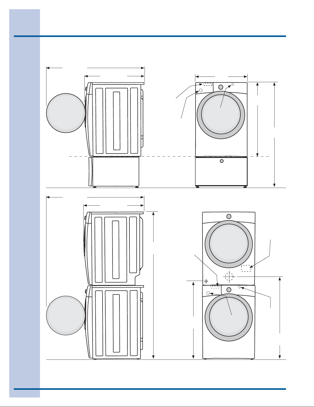
Washer dimensions
53.5” (136 cm)*
to clear open door
31.5” (79.5 cm)*
to front of closed door
27.0”
(68.5 cm)
freestand washer
on fl oor
fl oor line
washer mounted on
optional pedestal
fl oor line
53.5” (136 cm)*
to clear open door
31.5” (79.5 cm)*
to front of closed door
75.75”
(192.5 cm)
water supply
connection on
rear of unit
drain hose on
rear of unit
3
water supply
connection on
1
rear of unit
power cord on
1
rear of unit
38.0”
(96.5 cm)
53.25”
(135.5 cm)
electrical
supply on
rear of unit
3
fl oor line
*Connection of water inlet hose on steam dryer adds 3/4 in. (2 cm) to installation depth.
1
Power supply cord length on washer approximately 60 inches (152.5 cm).
2
Drain hose length on washer approximately 59 inches (150 cm).
3
Power supply cord length on gas dryer approximately 60 inches (152.5 cm).
gas supply
pipe on rear
of gas unit
39.0”
(99 cm)
drain hose on
2
rear of unit
centerline
height for
rear vent
power cord on
1
rear of unit
(105 cm)
41.0”
 Loading...