

Electrolux EIDW6405HT - Fully Integrated Dishwasher Installation Instructions Manual
Dishwasher
Installation
Instructions
Prnted n US A
154747401
10/10
INSTALLER: Leave Installation Instructionswith owner.
OWNER: Read your dishwasher Use and Care Guide It contains
important safety information for operating this appNance, n also has
many suggestions for getting the best resuns from your dishwasher.
Read all instructions before installing dishwasher.
For your safety, please read and observe an safety
instructions. This guide will help you anticipate drain, water, and
electrical connections, and help you select the best location for the
dishwasher.
Tip Over Hazard
Do not use dishwasher until completely installed.
Do not push down on open door.
Failure to follow this warning can result in serious
injury.
Cut Hazard
To prevent serious injury from sharp edges, wear work
gloves when handling, unpacking or disassembling unit,
Tools and Materials Needed for
Installation (Not Included)
Ddll, Electric
Ddver, Socket 5/32",'/4" ,5/,"
Flaring Tool /Tube Cutter (for copper tubing)
Flashlight
Level
Pipe Joint Compound (for iron pipe plumbing) or
Pipe Thread Tape (forseaNng threads)
• Pliers
Safety Glasses
Saw, Keyhole or V2", 1V2" to 2" Hole Cutters
Screw Drivers, Slotted and #2 Phillips (magnetic6p
preferred)
Tape, Electrical or Duct
Tape, Measuring
Wire Stripper or Utility Knife
Wrench, Hex-end
Ddll Bit Vs"
# 32 Drill Bit (V_") (optional)
Wrenches, 2AdjuWable (for copper tubing)
or 2 Pipe wrenches (for iron pipe plumbing)
Parts You Will Need* (NotIncluded)
• Drain Hose Clamp, 1eg Diameter
• Brass Elbow, 90' with a 3/d' National Pipe Thread
• Conduit Connector (UL Listed)
• Wire Nuts, three (3) for 12-14 gauge wire (UL Listed)
• 2 # 7 V2"screws (optional)
If required:
• "Y"Branch Tailpiece and
Connector Kit (See Step 4)
• Air Gap Kit (See Step 4)
All the parts can be found at local hardware, electrical and
plumblng supply stores.
NOTE: Put unit on its back being careful not to pinch the Water
Drain Hose.
1. Remove two (2) screws at front of the kickplate assembly using a
#2 Phillips screw driver.
2, Tilt and pull forward to remove see figure 1.
Kickplat6
Toeplate
Kickplale ,-t __embly
Figure 1
3. Locate water inlet valve behind kickplate on bottom left underside
of unibSee Fig ure 4. The valve has a 3/8"NPT female rifting.
Remove Plug
4. Wrap 90° elbow (not included) with pipe thread tape (or apply
joint compound) and thread itinto water inlet valve. When
tightened, elbow should point toward the lee. To prevent bending
of bracket or breaking of valve, avoid overlightening.
See Figure 4.
Cabinet Preoaration:
As a precaution, it is recommended, but not required that the
cabinets enclosing all sides of the dishwasher (including the
underside of the countertop) be sealed with an oil based paint
or moisture-proof polyurethane to prevent possible steamf
moisture damage.
electrical and plumbing connections, All electrical
and plumbing work should be performed by
q ua6fled persons. Failure to follow this warning
could result in death or serious injury.
1. Make sure your location has the correct drain, water, and
electrical outlets to make the connections. Do not instafl unit
under a cooklop range. Damage to tub or other components will
occur.
k4
Figllre 2
Figm"e3 i_suarl_ _L_ _YBECOMPaESSEOUPO_
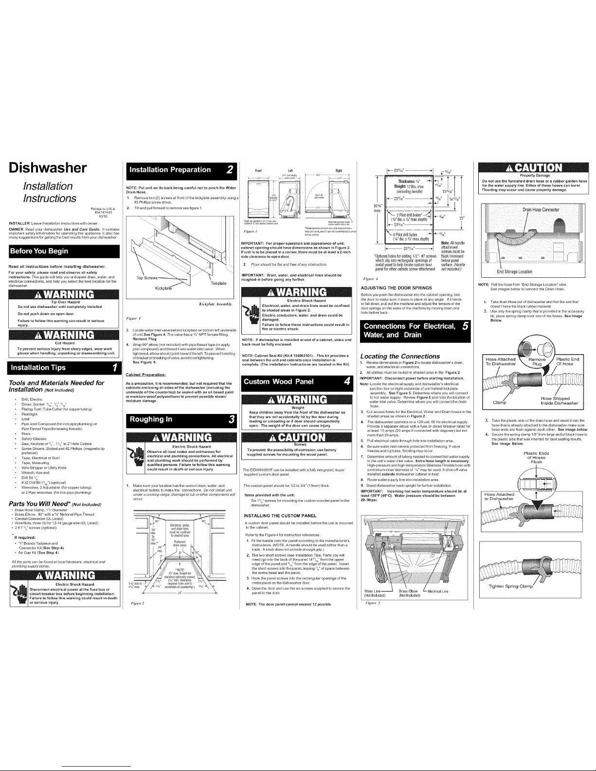
IMPORTANT: For proper operation and appearance of unit,
cabinet opening should have dimensions as shown in Figure 2,
If unit is to be placed in acorner, there must be at least a 2-inch
side clearance to open door.
2, FIoor should be flat and free of any obstruction.
IMPORTANT: Drain, water, and electrical lines should be
roughed-in before going any further.
NOTE: If dishwasher is installed at end of a cabinet, sides and
back must be fully enclosed.
NOTE: Cabinet Seal Kit (Kit # 154662101). This kit provides a
seal between the unit and cabinets once installation is
complete. (The Installation Instructions are located in the Kit)
! i ," _ k
Weight
Keep children away from the front of the dishwasher so
that they are not accidentany hit by the door during
loading or unloading or if door should unexpectedly
open. The weight of the door can cause injury.
Screws
To prevent the posssibi6ty of corrosion, use factory
supplied screws for mounting the wood panel,
The EIDW6405HT can be installed with a fully integrated, buyer
supplied custom door panel.
The custom panel should be 1/2to 3/4" (19mm) thick.
Items provided with the unit:
Six 1_/8"screws for moun0ng the custom wooden panel to the
dishwasher.
INSTALLING THE CUSTOM PANEL
A custom door panel should be installed before the unit is mounted
to the cabinet.
Refer to the Figure 4 for instruction references.
1. Fit the handle onto the panel according to the manufacturer's
instructions. (NOTE: A handle should be used rather than a
knob. A knob does not provide enough grip.)
2. The two short screws (see Installation Tips, Parts you will
need) go into the back of the panel 14W3_"from the upper
edge of the panel and _/_" from the edge of the panel. Insert
the short screws into the panel, leaving V_"of space between
the screw head and the panel.
3. Hook the panel screws into the rectangular openings of the
metal panel on the dishwasher door.
4. Open the door and use the six screws supplied to secure the
panel to the door.
NOTE: The door panel cannot exceed 12 pounds.
WeigN: 12 Ibs. el_x,
i_4u#:% h3_#et
2Pilot d_illhc_eo* -/_1
(Vd' alia,_ _A"ma:_+de_th)
*- 23 %,_"
%- 6 Pilot drill fiole_ _-_I
{%" dim a¾" r3e;cde_,th)
_|
"!d + 114_:'/_" /
llot_: f_l h_odb
efteeh r{leot
_efeveT,fetlll_ be
*0pfleoelholesforeddie§1/2"-#7sore_s ltssh!feoes_,elf
whichslipinto recta%olaf@eningoof belowp3nel
me_31paneltohelp 17ocateoostomdoor sg#lce L_ll_'/e
pa#elfc_e#lerouts{descrew31techrneo_ i_tir_/uded,)
Figure 4
ADJUSTING THE DOOR SPRINGS
Before you push the dishwasher into the cabinet opening, test
the door to make sure it stays in place at any angle. Ifit tends
to fall down, pull out the machine and adjust the tension of the
door springs on the sides of the machine by moving them one
hole farther back.
Locating the Connections
1. Review dimensions inFigure 2 to locate dishwasher's drain,
water, and electrical connections.
2, All utilities must be routed in shaded area in the Figure 2.
IMPORTANT: Disconnect power before starting installation.
Note: Locate the electrical supply and dishwasher's electrical
junction box on right underside of unit behind kickplate
assembly. See Figure 5. Determine where you will connect
to hotwater supply. Review Figure 5 and note the location of
water inlet valve. Determine where you will connect the drain
hose.
3. CutaccesshoiesfortheEiectdcaI, WaterandDrainhosesintbe
shaded areas as shown in Figure 2,
4. The dishwasher operates on a 120 volt, 60 Hz electrical supply.
Provide a separate circuit with a fuse or circuit breaker rated for
at least 15 amps (20 amps if connected with disposer) but not
more than 20 amps.
5. PUll electrical cable through hole into installation area.
6. Be sure water inlet valve is protected from freezing. If valve
freezes and ruptures, flooding may occur.
7. Determine amot.mt of tubing needed to connect hot water supply
to the uniPs water inlet valve. Extra hose length is necessary.
High-pressure and high-temperature Stainless Flexible hose with
a minimum inner diameter of '/g' may be used. A shut-off valve
inWalled outside dishwasher cabinet is best.
8, Route water supply line intoinstalia6on area.
9. Stand dishwasher back updght for further instaliaOon.
IMPORTANT: Incoming hot water temperature should be at
least 120°F (49°C). Water pressure should be between
20-90 psi,
(Not Included)
Fig.re 5
Brass Elbow Electrical Line
(Not Included)
! _ O k
Property Damage
Do not use the furnished drain hose or a rubber garden hose
for the water su pply line, Either of these hoses can burst,
Flooding may occur and cause property damage.
End Storage Location
NOTE: Pull the hose from "End Storage Location" side.
See images below to connect the Drain Hose.
l. Take drain Hose out of dishwasher and find the end that
doesn't have the black rubbe rmaterial.
2. Use only the spring clamp that isprovided in the accessory
kit, place spring clamp over one of the hoses. See Image
Below.
Hose Attached
To Dishwasher
Hose Shipped
Inside Dishwasher
3. Take the plastic side of the drain hose and insert it into the
hose that is already attached to the dishwasher make sure
hose ends are flush against each other. See image below.
4. Secure the spring clamp 1/8" from large end of black hose to
the plastic side that was inserted for best sealing resuns.
See Image Below.
Plastic Ends
of Hoses
Flush
Hose Attached
Tighten Spring Clamp
1. Measure height of cabinetopening from underside of
countertop tofloor. Check chartfor height opening and
suggested adjustment.
Leg Leveler Adjustment Chart
Heightof Number of Tumsto
Cabinet Opening Adjust Levelers
34"(86.4cm) 0
34_8"(86.7cm) 2
34_" (87.2cm) 6
34_z"(87.6cm) 9
2, Move dishwasher to front of installation area.
3. Loosen the rear ]evefing legs by turning counterclockwise. Refer
to chart for number of turns.
Dishwasher Anchoring
4. instal] the Cabinet Seal Kit (Instn.lctions included in Kit)
5. Choose one of the methods of attachment below to secure unib
holes need to be pre-ddlled using a #5 ddll bit regardless of
the option chosen:
a. Side Mount Cabinet Clips (Preferred Method of
attachment)
b. Top Mount Cabinet Clips (to be used when Side Mount
is not an available option)
CAUTION: Use extreme care in mounting the dishwasher as to
not scratch, bump or otherwise damage the console or tub.
To install the Side Mounting Clips,
Depending on space allowed in cabinet the Side Mounting
Clips can be installed with the holes for the screw Lip (preferred
method) or down as shown in the illustrations below. (Use extreme
caution when the dips are in the down position while installing
the dishwasher).
NOTE: Install Side Mount Brackets before unit is installed into
the cabinet. Insert screws intothe front holes of the
mounting clips only. (See image below)
Use {f measures 341/_'' to 35"
Use if measu,_s 34" to 34V_"
TO install using Top Mou nt Cabinet Clips: Depending on the
depth of cabineb the Top Mount Clip have a break off point
that can be removed if necessary.
NOTE: Install Top Mount Clips before unit is installed into
the cabinet. Screw clips flrrnly to top brace using screws
provided in the literature pack. (See image below)
6, If levelers need to be removed, make sure that the floor isfree of all
obstr_lcfions.
7. Care fully place dishwasher inside cabinet area such that is
centered in opening. Use caution when moving dishwasher to
prevent damage to cabinet, dishwasher and floor.
8. Front of door needs to be even with the front of adjoining cabinets.
Front levelers ShOLddallow 5/16" below underside ofcountertop
to top of console.
9. Check that dishwasher is level from side to side by placing a level
against the top front section of the tub. See Figure 6a.
10. Check that the dishwasher is level from front to back by taking
out the lower rack, place level on the lower rack wheel support at
the bottom of the tub. See Figure 6b.
11. Adjust levelers Lipor down until dishwasher is level.
Holes need to be pre-drified using a #5 drill to secure unit.
12. Screw mounting brackets firmly to cabinet using screws provided
in literature packet. See Image Below.
Figztre 6c Figttre 6d
13. Open and close dishwasher door slowly. Ensure that there is
clearance to the console. Adjust accordingly unfil door opens
and closes freely.
Property Damage
Do not solder within 6" of the water inlet valve. Damage to
the plastic parts in the valve may occur.
Use care that no sealer, dirt, or other objects enter the valve.
Damage to the filter screen may occur.
Be sure the dishwasher is placed where the water inlet
valve will be kept from freezing. If the valve freezes, it may
rupture and flooding may occur.
Water Line
1, FlUsh water line before connecting it towater inlet valve to
prevent early clogging of filter screen. Place a bunched towel
over end of line to prevent splashing. Open water supply valve for
a few seconds and let water drain into a pan. Turn off water
supply at shut-off valve.
2. Rot.de water line to water inlet valve as shown in Figure 5.
3. While firmly pulling water supply line into 90 ° elbow, tightly
connect water supply to water inlel valve. Supply line must be
free of kinks, scales, chips, and lubricants.
4. Turn on water supply and check for leaks.
Electrical Supply
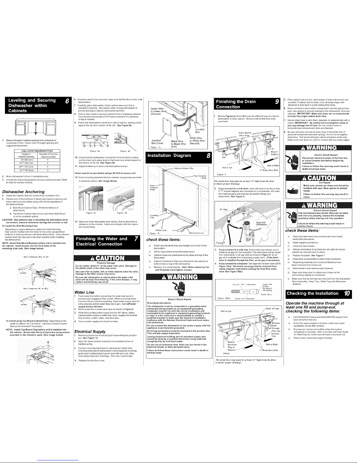
1. Remove junction box cover and pui] house widng into junction
box. See Figure 7a.
2, Use a UL listed conduit connector (not included) at box to
stabilize wiring.
3. Connect incoming black lead to dishwasher's black lead,
incoming white lead to dishwasher's white lead and incoming
green lead to dishwasher's green lead with wire nuts. (See
Grounding Instruction Warning). Wire nuts must be tight.
4. Replace junction box cover.
Box
White Wire
Junction Wire to White Wire
Box Cover to Black Wire (Neutral)
Figm'e 7a (Hot)
Figure 71)
check these items:
Water and electrical lines are straight out in front of the
dishwasher.
All four leg levelers are positioned properly.
Cabinet Seals are positioned on the sides and top of the
dishwasher.
Cabinet Attachment Clips are attached to the cabinet on
both comers on top of the dishwasher.
Replace Toe and Kickplate. Note: When replacing Toe
and Kickplate hand tighten screws.
Electric Shock Hazard
Grounding Instructions:
The dishwasher must be connected to a grounded metal,
permanent wiring system or an equipment-grounding
conductor must be run with the circuit conductors and
connected to the appliance's equipment grounding terminal
or lead. ]t is the consumer's responsibility to contact a
qualified installer to make sure the electrical installation
conforms with the National Electrical Code and local codes
and ordinances.
Do not connect the dishwasher to the power supply until the
appliance is permanently grounded.
All wiring connections must be enclosed in the junction box.
This unit has copper lead wires.
Joining aluminum building wire to stranded copper wire
should be done by a qualified electrician using materials
recognized by UL and local codes.
Do not use an extension cord. Such use can result in fire,
electrical shock, or other personal injury.
Failure to follow these instructions could res ult in death or
serious injury.
1. Review Figures 8, 9 and 10 to see the different ways to connect
dishwasher to drain system. Choose method that best suits
yourneed.
Jf Sink at R_h,
Sink ,t L_#
F_.re 8
The drain hose h)op mu_t be at least 32" high [rom the [Ioor
to insuraproper draimtga,
2, If you connect to a sink drain, entry will need to be above trap.
A "Y" branch tailpiece and connector kit, not included, will make
this method easier and includes all needed fillings and
instructions. See Figure 8.
3. If you connect to a sink trap, local codes may require you to
install an air gap kit, (not included). The drain hose will be routed
from dishwasher to air gap inlet as shown in Fig ure 9. An air
gap kit is available from a plumbing supply store. (If the drain
hose is installed through the floor, an air gap is necessary).
4. If you connect to a disposer, the large end of drain hose will fit.
Fig ure 10(a). The knock out plug must be removed from
inside disposer inlet before making the final fit to drain
hose See Figure 10(b).
/
Figttre lOpO Cuth_t 3/4"_,mne_tion,
Sink at Le# _ "_a_a_tit Gap
C _\ ' " _D "
109(b)
The drain hose h)op mu_t be at h,a_t 32" high [rom the [loor
to insm'e proper _'ainag_
5. [fthe cabinet wall is wood, sand edges of hole until smooth and
rounded. If cabinet wall is metal, cover all sharp edges with
eleclrical or duct tape to avoid cutting drain hose.
Move unit back in place while routing drain hose through access
hole. Use caution to prevent damage to the dishwasher, floor and
cabinets. IMPORTANT: Make sure there are no sharp bends
or kinks that might restrict drain flow.
Secure drain hose to sink drain, disposer, or separate trap with a
clamp. IMPORTANT: Be careful not to overtighten clamp or
you may damage end of hose. Do not connect hose to
horizontal pipe between sink drain and disposer.
Be sure unit does not rest on drain hose. I_should be free of
electrical components and door spnngs. Do not cut corrugated
drain hose. PLdl excess through cabinet and place under sink.
Make sure hose does not come in contact with any sharp edges.
Electric Shock Hazard
Disconnect electrical power at the fuse box
or circuit breaker box before beginning
installation.
Failure to follow this warning could result in
death or serious injury.
Failure to follow this warning may result in
injury.
check these items:
Water and drain lines have no kinks and move freely
behindthe dishwasher.
Water supply is turned on.
Joints are free of leaks.
Wiring connections to junction box are tight all access
panels are secured back in place.
Replace kickplate. See Figure 1
Drain hose is assembled to Drain Hose Connector.
All packing materials and consumer literature have
been removed from inside unit.
Dishwasher is level and securely fastened.
Open and dose door to make sure it does not hit
surrounding cabinet or countertop.
Make sure that allwire ties are removed from the Adjustable
Rack Assembly, Versa Tray, Utility Tray and Silverware
Baskets.
Operate the machine through at
least one fill and pump-out,
checking the following items:
On EIDW6405HT press and hold SANITIZE keypad for 8
seconds before first use.
At first fill, approximately 2 minLdes, make sure water
completely covers filter surface.
At pump-ouh (pump_ut is either when the cycle is
completed or canceled, refer to the Use and Care Guide
for Stad/Cancel), make sure all water is pumped ouk
Check water connections again for leaks.
 Loading...