

Page 1
Installation, Use & Care Guide
30”(76.2 cm), 36”(91.4 cm) and 48”(121.92 cm) Hood Insert
Guide d’installation, utilisation
et d’entretien
30”(76.2 cm), 36”(91.4 cm) et 48”(121.92 cm) Doublure de Hotte
Guia de Instalación, Uso y Cuidado
Campana de línea de 30”(76.2 cm), 36”(91.4 cm) y 48”(121.92 cm)
EI30HI55KS + EI36HI55KS + EI48HI55KS
LI30FA Ed. 08/11
316902479
Page 2
2
Finding Information
Please read and save this guide
Thank you for choosing Electrolux, the new premium brand in home appliances. This Use & Care Guide is
part of our commitment to customer satisfaction and product quality throughout the service life of your new
appliance.
We view your purchase as the beginning of a relationship. To ensure our ability to continue serving you,
please use this page to record important product information.
Keep a record for quick reference
Purchase date
Model number
Serial number (see picture for location)
NOTE
Registering your product with Electrolux enhances
our ability to serve you. You can register online at
www.electroluxappliances.com by dropping your
Product Registration Card in the mail.
Questions?
For toll-free telephone support in the U.S. and Canada:
US.: 1.800.944.9044 / Canada: 1.800.265.8352
For online support and Internet product information visit http:// www.electroluxappliances.com
Table of contents
Important Safety Instructions ............................. ... 3
List of materials...................................................... ... 4
Electrical requirements ........................................ ... 5
Location requirements . .......................................... 6
Product dimensions ................................................. 6
Venting Requirements............................................... 7
Venting methods........................................................................ 7
Install Hood Insert Internal
Blower Motor.............................................................. 8
Remote Blower Motor Installation
into Hood Insert......................................................... 10
Prepare the location.................................................. 12
Install Hood Insert into Hood Cabinet.................... 13
Make Electrical Power Supply
Connection to Hood Insert....................................... 14
Complete Installation and Check Operation........ 14
Hood Insert Use......................................................... 15
Cleaning....................................................................... 15
Warranty Information................................................ 16
©2011 Electrolux Home Products, Inc. All rights reserved. Printed in Mexico
Page 3
Important Safety Instructions
Read all instructions before using this
appliance.
Save these instructions for future
references
Approved for residential appliances
For residential use only
Do not attempt to install or operate your appliance
until you have read the safety precautions in this
manual. Safety items throughout this manual are
labeled with a WARNING or CAUTION based on the
risk type.
This symbol alerts you to
situations that may cause
serious body harm, death
or property damage.
Important Safety Instructions
3
This symbol alerts you to
situations that may cause
bodily injury or property
damage.
PLEASE READ ENTIRE INSTRUCTIONS BEFORE PROCEEDING.
INSTALLATION MUST COMPLY WITH ALL LOCAL CODES.
IMPORTANT: Save these Instructions for the Local Electrical Inspector’s use.
INSTALLER: Please leave these Instructions with this unit for the owner.
OWNER: Please retain these instructions for future reference.
Safety Warning: Turn off power circuit at service panel and lock out panel, before wiring this appliance.
Requirement: 120 V AC, 60 Hz. 15 or 20 A Branch Circuit
Page 4

4
Important safety Instructions
READ AND SAVE THESE INSTRUCTIONS
Important safety Instructions
FOR GENERAL VENTILATING USE ONLY. DO NOT USE
TO EXHAUST HAZARDOUS OR EXPLOSIVE
MATERIALS OR VAPORS.
TO REDUCE THE RISK OF FIRE, ELECTRIC SHOCK,
OR INJURY TO PERSONS, OBSERVE THE
FOLLOWING:
Use this unit only in the manner intended by the
A.
manufacturer. If you have questions, contact the
manufacturer
Before servicing or cleaning the unit, switch power off
B.
at service panel and lock service panel disconnecting
means to prevent power from being switched on
accidentally. When the service disconnecting means
cannot be locked, securely fasten a prominent warning
device, such as a tag, to the service panel.
Installation Work and Electrical Wiring Must Be Done By
C.
Qualied Person(s) In Accordance With all Aplicable
Codes & Standards, Including Fire-rated Construction.
Sufcient air is needed for proper combustion and ex
D.
hausting of gases through the ue (Chimney) of fuel
burning equipment to prevent back- drafting. Follow
the heating equipment manufacturers guideline
and safety standards such as those published by
the National Fire Protection Association (NFPA),
the American Society for Heating, Refrigeration and Air
Conditioning Engineers (ASHRAE), and the local code
authorities.
When cutting or drilling into wall or ceiling, do not
E.
damage electrical wiring and other hidden utilities.
Ducted systems must always be vented to the
F.
outdoors.
To reduce risk of re and to properly exhaust air, be sure to
duct air outside - do not vent exhaust air into spaces within
walls, ceilings, attics, crawl spaces, or garages.
TO REDUCE THE RISK OF FIRE, USE ONLY METAL
DUCT WORK.
Install this hood insert in accordance with all requirements
specied.
TO REDUCE THE RISK OF A RANGE TOP GREASE
FIRE.
Never leave surface units unattended at high settings.
a)
Boilovers cause smoking and greasy spillovers that
may ignite. Heat oils slowly on low or medium settings.
Always turn hood ON when cooking at high heat or
b)
when ambeing food (l.e. Crepes Suzette, Cherries
Jubilee, Peppercorn Beef Flambe’).
Clean ventilating fans frequently. Grease should not
c)
be allowed to accumulate on fan or lter.
Use proper pan size. Always use cookware appropriate
d)
for the size of the surface element.
TO REDUCE THE RISK OF INJURY TO PERSONS, IN
THE EVENT OF A RANGE TOP GREASE FIRE,
OBSERVE THE FOLLOWING:
SMOTHER FLAMES with a close - tting lid, cookie
a)
sheet, or other metal tray, then turn off the gas burner
or the electric element. BE CAREFUL TO PREVENT
BURNS. If the ames do not go out immediately,
EVACUATE AND CALL THE FIRE DEPARTMENT.
NEVER PICK UP A FLAMING PAN - you may be
b)
burned.
DO NOT USE WATER, including wet dishcloths or
c)
towels - a violent steam explosion will result.
Use an extinguisher ONLY if:
d)
You know you have a class ABC extinguisher,
1)
and you already know how to operate it.
The re is small and contained in the area
2)
where it started.
The re department is being called.
3)
You can ght the re with your back to an exit.
4)
OPERATION
Always leave safety grills and lters in place.Without these
components, operating blowers could catch onto hair,
ngers and loose clothing.
The manufacturer declines all responsibility in the event
of failure to observe the instructions given here for
installation,maintenance and suitable use of the product.
The manufacturer further declines all responsibility for injury
due to negligence and the warranty of the unit automatically
expires due to improper maintenance.
To Reduce The Risk Of Fire Or Electric Shock, Do Not
Use This Hood Insert With Any External Solid State Speed
Control Device.
Page 5

List of materials- Electrical & Installation
requirements
5
List of Materials
Parts included in your hood insert
Metal grease lters:
•
- Model EI30HI55KS: 2 lters
- Model EI36HI55KS: 3 lters
- Model EI48HI55KS: 4 lters
Hood insert with 4 halogen lamps installed.
•
1 - 10” (25.4 cm) square to 10” (25.4 cm) round
•
duct transition with damper.
4 - 5 x 45 mm mounting screws for cabinet
•
4 - 4.2 x 8 mm screws for 10” round ducting damper
•
2 - 18mm spacer screw (only for EI30HI55KS
•
hood insert model)
Parts Needed
Home power supply cable
•
1 - ½” (1.3 cm) UL listed or CSA approved strain relief
•
3 - UL listed wire connectors
•
1 wall or roof cap
•
Metal vent system
•
Blower motor system - internal or remote (see
•
“Blower Motor Options” section).
Tools/Materials required
Level
•
Drill
•
1¼” (3 cm) drill bit
•
11/8” (3 mm) drill bit
•
Pencil
•
Wire stripper or knife
•
Tape measure or ruler
•
Pliers
•
Blower Motor Options
(1 system is required with Vent Hood Insert)
BLOWER MOTOR SYSTEM KITS HOOD INSERT MODELS
MODEL RATING
EI06HIPIKS
(600 cfm Int. Blower Kit)
EI12HIPIKS
(1200 cfm Int.Blower Kit)
EI06HIPRKS
(600 cfm Remote Blower Kit)
EI12HIPRKS
(1200 cfm Remote Blower Kit)
You can use your range hood model with this blower motor kit.
3.7 A
7.4 A
3.7 A
7.4 A
Caulking gun and
•
weatherproof caulking
compound
Vent clamps
•
Jigsaw or keyhole saw
•
Flat-blade screwdriver
•
Metal snips
•
Phillips screwdriver
•
EI30HI55K5 EI36HI55K5 EI48HI55K5
• • •
• •
• • •
• • •
Electrical Requirements
Observe all governing codes and ordinances.
Ensure that the electrical installation is adequate and
in conformance with National Electrical Code, ANSI/
NFPA 70 (latest edition), or CSA Standards C22.194, Canadian Electrical Code, Part 1 and C22.2 No.
0-M91 (latest edition) and all local codes and ordinances.
If codes permit and a separate ground wire is used, it
is recommended that a qualied electrician determine
that the ground path is adequate.
A copy of the above code standards can be obtained
from:
National Fire Protection Association
One Batterymarch Park
Quincy, MA 02269
CSA International
8501 East Pleasant Valley Road
Cleveland, OH 44131-5575
A 120 volt, 60 Hz., AC only, 15-amp, fused
•
electrical circuit is required.
If the house has aluminum wiring, follow the
•
procedure below:
Connect a section of solid copper wire to the
1.
pigtail leads.
Connect the aluminum wiring to the added
2.
section of copper wire using special co
nectors and/or tools designed and UL listed
for joining copper to aluminum.
Follow the electrical connector manufacturer’s recommended procedure. Aluminum/copper connection
must conform with local codes and industry accepted
wiring practices.
Wire sizes and connections must conform with
•
the rating of the appliance as specied on the
model/serial rating plate.
The model/serial plate is located behind the lter
on the rear wall of the range hood.
Wire sizes must conform to the requirements of
•
the National Electrical Code, ANSI/NFPA 70 (la
est edition), or CSA Standards C22. 1-94,
Canadian Electrical Code, Part 1 and C22.2
No. 0-M91 (latest edition) and all local codes and
ordinances.
CAUTION
To reduce the risk of re and electric shock, install
this hood insert only with internal and remote
blower models rated maximum 7.4 A
(Electrolux™).
Page 6

6
Location requirements
Location Requirements
IMPORTANT: Observe all governing codes and ordinances. Have a qualied technician install the hood
insert. It is the installer’s responsibility to comply with
installation clearances specied on the model/serial
rating plate. The model/serial rating plate is located
behind the left lter on the rear wall of the hood
insert.
The hood insert location should be away from strong
draft areas, such as windows, doors and strong heating vents.
Cabinet opening dimensions that are shown must be
used. Given dimensions provide minimum clearance.
The hood insert must be surrounded by a custom built
enclosure with hood cabinet capable of supporting 75
lb (34 kg).
Grounded electrical outlet is required. See “Electrical
Requirements” section on page 5.
All openings in ceiling and wall where canopy hood
will be installed must be sealed.
For Mobile Home Installations
The installation of this hood insert must conform to the
Manufactured Home Construction Safety Standards,
Title 24 CFR, Part 328 (formerly the Federal Standard
for Mobile Home Construction and Safety, Title 24,
HUD, Part 280) or when such standard is not applicable, the standard for Manufactured Home
Installation 1982 (Manufactured Home Sites, Communities and Setups) ANSI A225.1/NFPA 501A, or latest
edition, or with local codes.
Cabinet Dimensions
30” (76.2 cm) for 30” models
36” (91.4 cm) for 36” models
48” (121.9 cm) for 48” models
Hood insert cabinet must be
capable of supporting
75 lb (34 kg)
“X” bottom of canopy to
cooking surface
22”
(55.9 cm)
Hood insert
depth
IMPORTANT:
Minimum distance “X”: 24” (61 cm) from electric cooking surfaces.
Minimum distance “X”: 30” (76.2 cm) from gas cooking surfaces.
Suggested maximum distance “X”: 36” (91.4 cm).
Product dimensions
36” & 48” models
wiring knockout
8
”
(31.4 cm)
16
” (12.2 cm)
(29.2 cm)
16
”
(12.8 cm)
245/16”(61.8cm) for 30” models
30” (75.8 cm) for 36 & 48” models
30” (76.2 cm) for 30” models
36” (91.4 cm) for 36” models
48” (121.4 cm) for 48” models
22” (56 cm) for 30”models
271/2”(70 cm) for 36 & 48”models
97/8” (25.11 cm)
15” (38 cm) for 30” models
18” (45.2 cm) for 36” models
24” (61 cm) for 48” models
30” model
wiring knockout
11” (28 cm)
11” (28 cm) for 30” model
10 1/8” (25.7 cm) for 36 & 48” models
22” (55.9 cm)
Page 7
Venting Requirements
Vent system must terminate to the outdoors.
•
Do not terminate the vent system in an attic or
•
other enclosed area.
Do not use 4” (10.2 cm) laundry-type wall caps.
•
Use metal vent only. Rigid metal vent is
•
recommended. Plastic or metal foil vent is not
recommended.
The length of vent system and number of elbows
•
should be kept to a minimum to provide efcient
performance.
For the most efcient and quiet operation:
Use no more than three 90° elbows.
•
Make sure there is a minimum of 24” (61.0 cm) of
•
straight vent between the elbows if more than 1
elbow is used.
Do not install 2 elbows together.
•
Use clamps to seal all joints in the vent system
•
and use furnace duct tape to fully seal joint
connection.
Use caulking to seal exterior wall or roof opening
•
around the cap.
The size of the vent should be uniform.
•
Cold weather installations
An additional back draft damper should be installed
to minimize backward cold air ow as part of the vent
system.
A thermal break should be installed to minimize conduction of outside temperatures as part of the vent
system.
The damper should be on the cold air side of the
thermal break.
The break should be as close as possible to where the
vent system enters the heated portion of the house.
Makeup air
Local building codes may require the use of makeup
air systems when using ventilation systems greater
than specied CFM of air movement. The specied
CFM varies from locale to locale.
Consult your HVAC professional for specic requirements in your area.
Venting Methods
The hood exhaust opening has a 10” diameter
•
round vent outlet.
On installations using the 600 CFM Blower Motor
•
Systems, a 6” or 8” round vent system is
recommended.
Venting Requirements
On installations using the 1200 CFM Blower Motor
•
Systems, a 10” round vent system should be
used.
You can use a smaller round vent system , but
•
there will be a louder sound level.
NOTE: Flexible vent is not recommended.
Flexible vent creates back pressure and air
turbulence that greatly reduce performance.
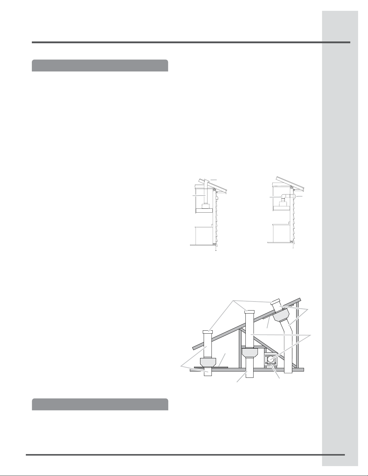
Vent system can terminate either through the
roof or wall. To vent through the wall, a 90° elbow
is needed.
Roof venting
A
A. 10” (25.4 cm) round vent
B. Roof cap
B
Wall Venting
A
A. 10” (25.4 cm) round vent
B.Wall cap
Typical Remote Blower Motor System Venting
Installations
C
E
D
B
A
A. 10” (25.4 cm) round vent
B. Mount on top of ceiling joists.
C. Roof caps
D. Plywood (optional for some installations)
E. Mount on underside of roof rafters.
F. Mount from cross-members tied to trusses.
G. Duct horizontal; mount to cross-members tied to trusses.
H. Wall cap
D
F
G
A
H
B
A
7
A
Page 8
8
Blower Motor Systems Installation
Install Hood Insert Internal
Blower Motor
The internal blower system can be mounted for top
venting.The mounting bracket and spring clip that
comes with the blower system will mount to the top
panel of the hood insert.
Internal Blower System Installation into Hood Insert
IMPORTANT: Perform steps 1-10 before mounting the
hood insert into the cabinet.
NOTE: Mounting hardware is included with the Blower
Motor System.
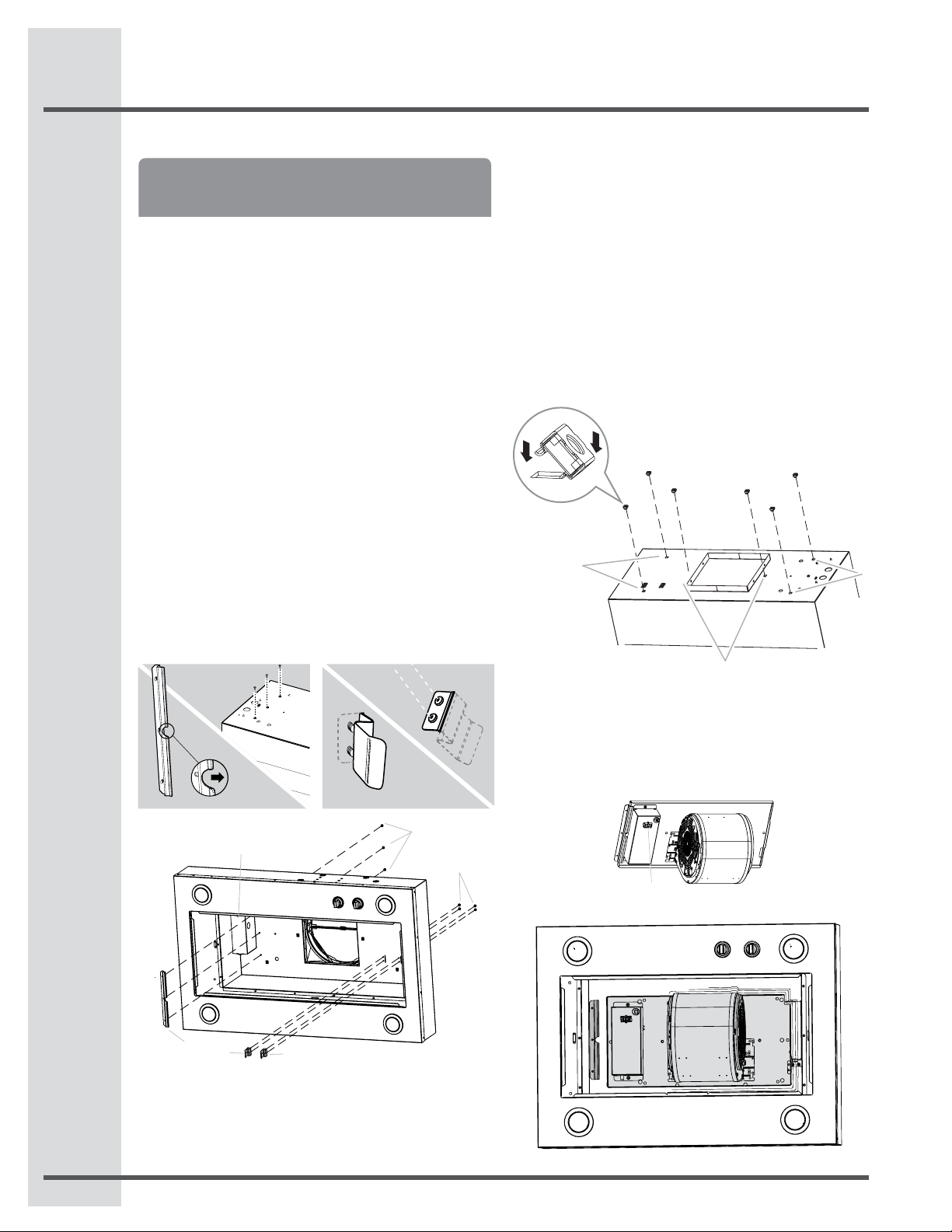
1.
Remove grease lters from hood insert. See the
“Cleaning” section in the Use and Care Guide.
2.
Install the motor support bracket using three 4.2 x
8 mm screws. Screw bracket to the inside top,
toward the left side of the hood insert (see step 2 figure).
3.
Install motor spring clip using two 4.2 x 8 mm
screws. Screw spring clip to the inside top of the
hood insert at the proper location for the selected
motor system. Slide the mounting tab of the
spring clip through the slot in the panel and secure
with the screws (see step 3 gure).
Outside the hood insert Outside the hood insert
Inside the hood insert Inside the hood insert
STEP 2 STEP 3
F*
A
C
D
A. 4.2 x 8 mm screws (3) for motor support bracket
B. 4.2 x 8 mm screws (2) for motor spring clip
C.Motor support bracket
D.Motor spring clip (single motor assembly location)
E.Motor spring clip (dual motor assembly location)
F. Terminal Box
* In model EI30HI55KS is located on the right side
E
B
Install the 6 mm clip nuts to the outside top
4.
of the hood insert at the proper location for the
selected motor system.
Two 6 mm nuts are required for 600 CFM
•
(single motor) Blower Motor Assembly.
Clip nuts into the small square notches
located at the left and right end of the
square vent opening.
Four 6 mm nuts are required for 1200 CFM
•
(dual motor) Blower Motor Assembly. Clip
nuts into the small square notches, located
at the left and right ends of the square vent
opening.
A. 6mm Clip Nut
B. Clip nut locations for single motor assembly (2)
C. Clip nut locations for dual motor assembly (4)
A
C
Install the hood insert blower motor assembly
5.
inside the hood insert canopy with the wiring
B
connection to the left for the single motor system
and to the front or top for the dual motor system
Single Blower Motor Assembly
A
A.Wiring connection
C
Page 9

Blower Motor Systems Installation
9
Dual Blower Motor Assembly
A.Wiring connection
A
To install blower motor assembly, slide the left
6.
mounting plate ange under the motor mounting
bracket.
A
Push the right end of the motor mounting plate
7.
down and snap it into the spring tab.
B
A.Motor mounting bracket
B.Mounting plate left ange
NOTE: The spring tab should be outside the slot
in the mounting plate.
A
B
A. Motor mounting plate
B. Spring clip
Align mounting holes and install 6 x 16 mm
8.
bolts and 6.4 mm lock washers.
A. Bolt with lock washer
B. Mounting hole
Attach power cord connector from the hood insert
9.
to connector on wiring box.
A. Wiring Box Connector
B. Hood Insert Connector
A
B
Install 10” round ducting damper with 4 - 4.2 x 8
10.
mm mounting screws.
Continue to Prepare the Location on page 12.
11.
A. 10” round ducting damper
B. Installation screws
A
B
A
BB
Page 10

10
Blower Motor Systems Installation
Remote Blower Motor
Installation into Hood Insert
Prepare for Mounting the Remote Blower System
The remote blower system must be fastened to a secure structure of the roof, ceiling, wall, oor, or new or
existing frame construction. The 4 holes on either the
inlet (bottom) side or the outlet (top) side of the blower
must be used to mount the remote blower system to
the structure.
NOTE: The mounting hole locations must span the
studs. Additional stud framing may be required.
Plywood may be used to span open areas between
ceiling joists or roof rafters to aid installation. This
structure must be strong enough to support the weight
of the remote blower system (50 lb [22.6 kg] min).
Prepare the Remote Blower System
Excessive Weight Hazard
Use two or more people to move and install
Remote blower motor system.
Failure to do so can result in back or other injury.
A. Front cover
B. Blower mounting bolts (4)
C. Spring clip
A
D. Motor electrical plug
B
C
D
Install Remote Blower Motor System
NOTE: The blower motor housing can be mounted
using 4 holes from either the inlet side or the outlet side
of the blower.
A
A
Inlet Side
Using two or more people, move the remote
1.
blower motor system to the mounting location.
Remove the 10 screws from the front cover of the
2.
remote blower motor housing and set them aside.
Remove the front cover of the remote blower
3.
motor housing and set it aside.
NOTE: To make the blower motor housing easier to
mount, the blower motor assembly can be removed. If
you do not want to remove the blower motor assembly, proceed to “Install Remote Blower System” in this
section.
To Remove Blower Motor
Disconnect the motor electrical plug from the
1.
blower motor assembly.
Remove the screws that secure the blower motor
2.
assembly to the remote blower housing and set
them aside.
Pull the spring clip to release the blower motor
3.
assembly. Remove the blower motor assembly
from the housing and place it on a covered
surface.
A. Mounting holes
A
A
Outlet Side
Position the remote blower motor housing in its
1.
mounting location and mark the 4 mounting hole
locations.
Drill 4 mounting pilot holes using a ³⁄16” (5 mm) drill bit.
2.
Attach the remote blower motor housing to the
3.
mounting location with four 6 x 80 mm mounting
screws and washers.
If Blower Motor is removed, reinstall the blower
4.
motor assembly and secure it with the screws
A
A
Page 11
Blower Motor Systems Installation
11
previously removed. If it is removed, reattach the
motor electrical plug to the connector on the
blower motor assembly.
Complete Preparation
Determine and make all necessary cuts for the
1.
vent system.
IMPORTANT: When cutting or drilling into the ceiling
or wall, do not damage electrical wiring or other hidden utilities.
Determine the location where the ½” (1.3 cm)
2.
wiring conduit will be routed through the ceiling or
wall between the remote blower and the hood insert.
Drill a 1¹⁄4” (3.2 cm) hole at this location.
3.
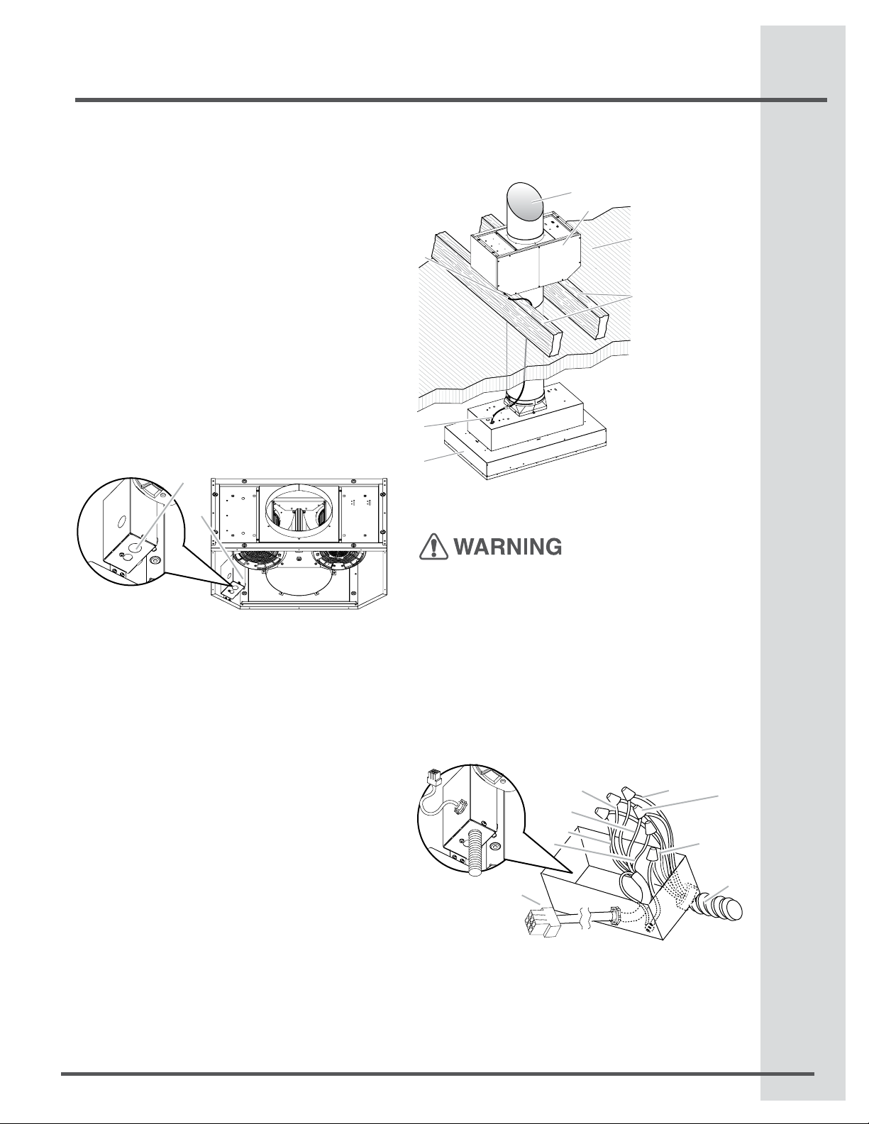
Locate the electrical terminal boxes in the remote
4.
blower housing and hood insert (see “Complete
Preparation” in the “Prepare Location” section).
Remove the terminal box covers and set the
covers and screws aside.
B
A
A. Electrical terminal box
B. Electrical knockout
Remove the electrical knockout from the remote
5.
blower housing and hood insert (see “Preparation”
in the “Prepare Location” section) to prepare for
the installation of the UL listed or CSA approved
½” (1.3 cm) wiring conduit and conduit connector.
NOTE: Strain relief conduit are supplied with
remote blower hardware.
With the hood insert mounted (see the “Install Hood
6.
Insert” section), run the ½” (1.3 cm) wiring conduit
between the remote blower motor housing and the
hood insert. Pull enough ½” (1.3 cm) wiring conduit
to allow for easy connection to the terminal boxes
in the remote blower housing and hood insert.
Run the six 18 AWG wires through the 1⁄2” (1.3
7.
cm) wiring conduit and conduit connectors and
into the terminal boxes on the remote blower
housing and hood insert. Leave enough wire length
in each terminal box to make the wiring connections.
Install the conduit connectors and conduit to the
8.
remote blower housing and hood insert electrical
terminal boxes.
NOTE: Strain relief conduit are supplied with
remote blower hardware.
Connect the vent system to the hood insert and
9.
remote blower motor system. Use clamps at all
joints. Use furnace duct tape to seal all joints
tightly.
E
A
B
C
D
F
G
A. Vent System
B. Remote Blower Motor
C. Ceiling
D. Roof rafters / Plywood
E. Remote Blower Wiring
Conduit
F. Hood Insert Wiring
Conduit
G. Hood Insert
Make Electrical Connections for Remote Blower
Motor System
Electrical Shock Hazard
Disconnect power before servicing.
Replace all parts and panels before operating.
Failure to do so can result in death or electrical
shock.
Electrical Connection Inside Remote Blower System
Disconnect power.
1.
Connect the wires from the wiring conduit to the
2.
wires from the motor electrical plug cable inside
the remote blower housing terminal box.
C
E
F
G
I
A.UL listed or CSA approved
1
⁄2” (1.3 cm) wiring conduit
B.UL listed wire connectors
C.Black wires
D.White wires
E. Red wires
F. Blue wires
G. Gray wires
H. Green (or yellow/green) and
green/yellow wires
I.Motor electrical plug cable
D
B
H
A
Page 12

12
Make Electrical Connections
Use UL listed wire connectors and connect the
3.
black wires (C) together.
Use UL listed wire connectors and connect the
4.
white wires (D) together.
Use UL listed wire connectors and connect the
5.
red wires (E) together.
Use UL listed wire connectors and connect the
6.
blue wires (F) together.
Use UL listed wire connectors and connect the
7.
gray wires (G) together.
Electrical Shock Hazard
Electrically ground blower.
Connect ground wire to green and yellow ground
wire in terminal box.
Failure to do so can result in death or electrical shock.
Connect the green (or yellow/green) ground wire
8.
to the green/yellow ground wire (H) in the terminal
box using UL listed wire connectors.
Reinstall the remote blower terminal box cover
9.
and screw.
Reinstall the front cover of the remote blower
10.
housing and secure it with 10 mounting screws.
Make Electrical Connection for Inside Hood Insert
Between Remote Blower Motor System and Hood
Insert
With the hood insert mounted (see the “Install
1.
Hood Insert” section), locate the wiring cable
connector inside the hood insert.
Connect the 6-wire connector assembly supplied
2.
with the remote blower motor system to the
mating cable connector from the hood insert.
Locate the terminal box inside the hood insert and
3.
install a ½” (1.3 cm) UL listed or CSA approved
strain relief.
Run the wire ends from the 6-wire connector a
4.
sembly through the ½” (1.3 cm) strain relief,
leaving enough wire length to make the wiring
conections. Tighten the strain relief screws.
Connect the wires from the 6-wire connector
5.
asembly to the wires from the remote blower
system wiring conduit inside the hood insert
terminal box.
Connect the same color wires to each other (black
6.
to black, white to white, etc.) using UL listed wire
connectors.
NOTE: Connect the green (or green/yellow) ground
wire from the Remote Blower Motor wiring conduit to
the green (or bare) ground wire from the home power
supply using UL listed wire connectors (refer to “Make
Electrical Power Supply Connection to Hood Insert”
section).
J K
B
A. UL listed or CSA approved
1
⁄2” (1.3 cm) wiring conduit
B. UL listed wire connectors
C. Black wires
D.White wires
E. Red wires
A
F. Blue wires
G.Gray wires
H. Green (or green/yellow) wire
I. 6-wire connector assembly
J. Home power supply knockout
K. Remote Blower Motor knockout
I
Ground Wiring
Connections
Home
Power Supply
Blower Motor
Go to the “Make Electrical Power Supply
7.
Wire
Conector
Remote
Connection to Hood Insert” section.
Prepare the Location
Disconnect power.
1.
Determine which venting method to use: roof or
2.
wall exhaust.
Select a at surface for assembling the hood
3.
insert. Place covering over that surface.
It is recommended that the vent system be
•
installed before hood is installed.
Before making cutouts, make sure there is proper
•
clearance within the ceiling or wall for exhaust vent.
Hood insert should be installed a minimum 24”
•
(61 cm) above an electric cooktop surface and 30”
(76.2 cm) above a gas cook top surface.
The maximum recommended height over both
cook tops is 36” (91.44 cm).
C
D
E
F
G
H
Hood
Insert
Page 13
Make Electrical Connections
13
Check that all installation parts have been
•
removed from the shipping carton.
Using 2 or more people, lift hood insert onto
4.
covered surface.
Remove the lters. See the “Cleaning”
5.
section on page 15.
Install Hood insert into
Hood Cabinet
The hood insert attaches to the hood cabinet using
four mounting screws and washers.
NOTE: Hood cabinet must be capable of supporting
75 lb (34 kg).
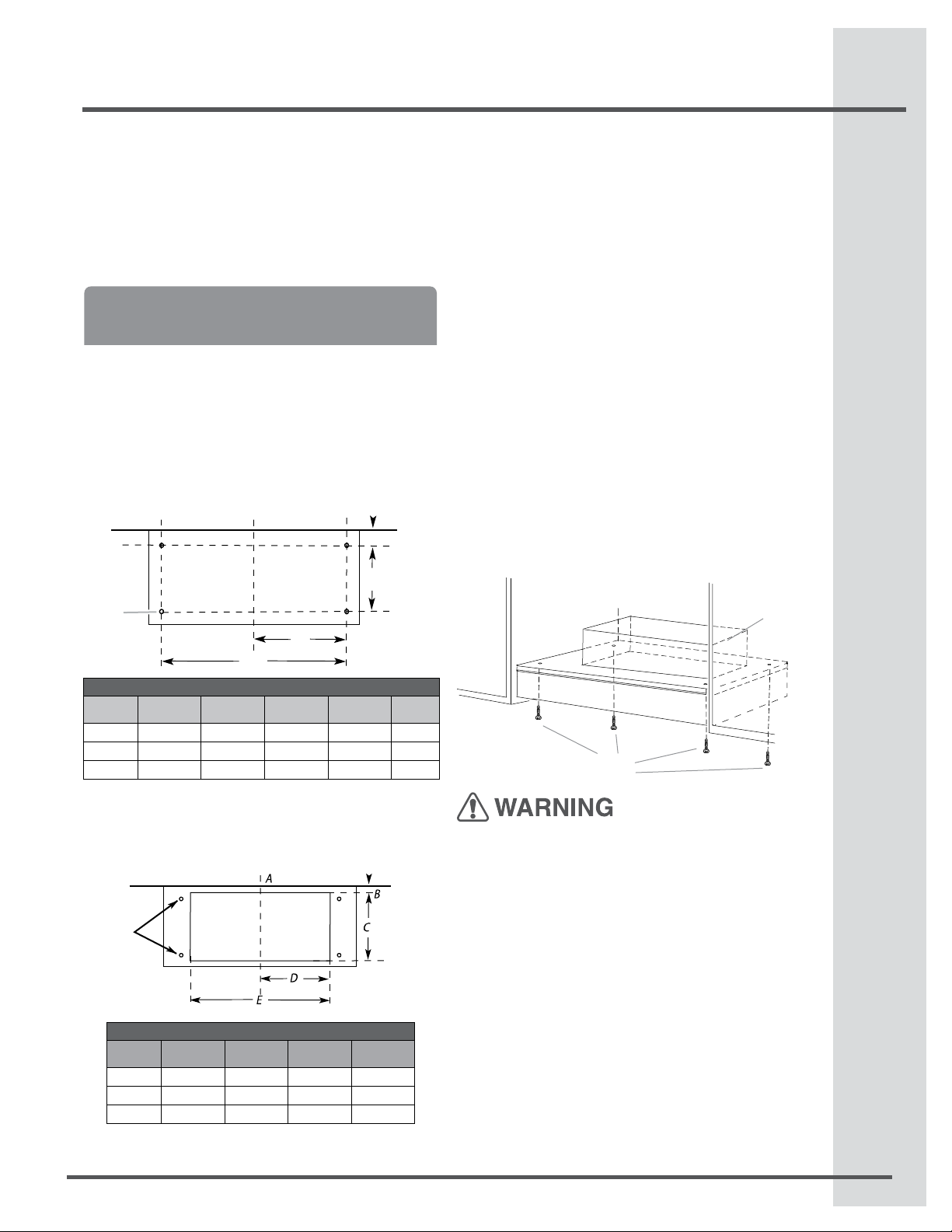
Prepare Hood Insert for mounting into cabinet
Mark the locations for the four mounting screws
1.
on the hood cabinet as shown below.
Using a ¹⁄8” (3 mm) drill bit, drill the 4 holes.
2.
F
A. Centerline
Hood
Insert
EI30HI55KS
EI36HI55KS
EI48HI55KS
3.
DIM B DIM C DIM D DIM E DIM F
51⁄2” (13.9 cm) 11” (28 cm) 125⁄32” (30.9 cm) 245⁄16” (61.8 cm) 1/8” (3mm)
6” (15.1 cm) 101⁄8” (25.7 cm) 1415⁄16” (38 cm) 2913⁄16” (75.8 cm) 1/8” (3mm)
6” (15.1 cm) 101⁄8” (25.7 cm) 1415⁄16” (38 cm) 2913⁄16” (75.8 cm) 1/8” (3mm)
Mark the cutout for the rectangular clearance hole
for the upper hood insert motor housing as shown.
Using a jigsaw or keyhole saw, cut out the rectan-
4.
gular clearance hole for the upper hood insert housing.
Mounting
holes
A. Centerline
A
D
E
MOUNTING HOLE DIMENSIONS
B
C
Complete Installation
Determine and make all necessary cuts in the
1.
wall or roof for the vent system. Install the vent
system before installing the cabinet hood insert.
See the “Venting Requirements” section.
Determine the location where the power supply
2.
cable will be run through the wall.
Drill a 1¹⁄4” (3.2 cm) hole at this location.
3.
Pull enough power supply cable through the wall
4.
to allow for easy connection to the terminal box.
Remove terminal box cover and set aside.
5.
Remove knockout from the top of the vent hood
6.
and install a UL listed or CSA approved ½”
(1.3 cm) strain relief.
Place the hood insert near its mounting position
7.
and run the power supply cable through the strain
relief into terminal box (enough to make connection).
Tighten the strain relief screws.
8.
Using 2 or more people, lift the hood insert into
9.
hood cabinet.
Fasten the hood insert using four 5 x 45 mm
10.
screws to the hood cabinet and tighten securely.
Insert Motor Housings
4 mounting
screws
EXCESSIVE WEIGHT HAZARD
USE TWO OR MORE PEOPLE TO MOVE AND
INSTALL HOOD INSERT.
FAILURE TO DO SO CAN RESULT IN BACK OR
OTHER INJURY.
Upper Hood
Hood
Insert
EI30HI55KS
EI36HI55KS
EI48HI55KS
UPPERHOOD MOTOR HOUSINgS DIMENSIONS
DIM B DIM C DIM D DIM E
413⁄32” (11.2 cm) 133⁄16” (33.5 cm) 1113⁄32” (29 cm) 2213⁄16” (58 cm)
413⁄32” (11.2 cm) 133⁄16” (33.5 cm) 143⁄16” (36 cm) 283⁄8” (72 cm)
413⁄32” (11.2 cm) 133⁄16” (33.5 cm) 143⁄16” (36 cm) 283⁄8” (72 cm)
Page 14
14
Make Electrical Connections
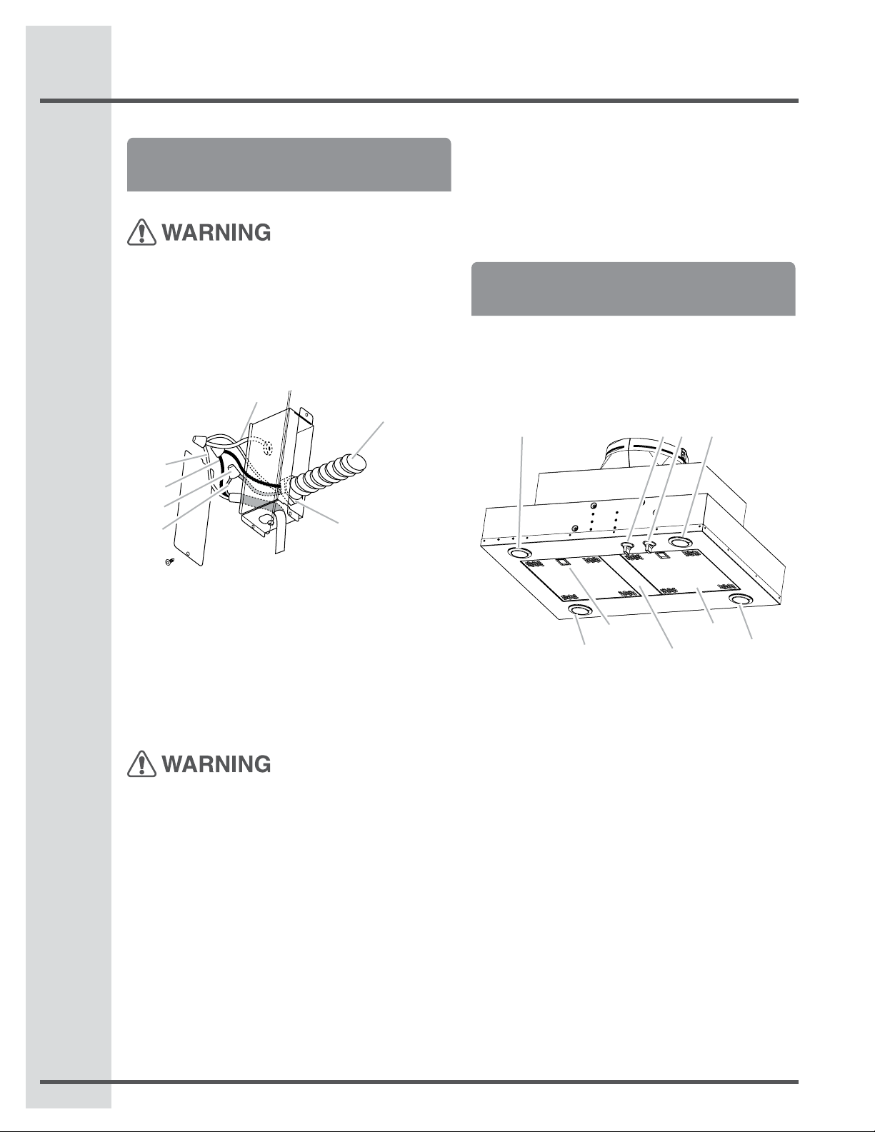
Make Electrical Power Supply
Connection to Hood Insert
Electrical Shock Hazard
Disconnect power before servicing.
Replace all parts and panels before operating.
Failure to do so can result in death or electrical
shock.
Disconnect power.
1.
Locate terminal box inside of the hood insert.
2.
A
B
C
D
A.White wires
B. Black wires
C. UL listed wire connectors
D. Green, bare or yellow/green wires
E.Home power supply
F. UL listed or CSA approved ¹⁄2” (1.3 cm) strain relief
G. Ground Wire tab
Use UL listed wire connectors and connect black
3.
wires (B) together.
Use UL listed wire connectors and connect white
4.
wires (A) together.
Electrical Shock Hazard
Electrically ground blower.
Connect ground wire to green and yellow ground
wire in terminal box.
Failure to do so can result in death or electrical
shock.
NOTE: When using an Remote blower motor system,
the green (or green/yellow) ground wire in the conduit
from the Remote blower motor system is to be
connected with the green (or bare) wire of the home
power supply cable and with the green/yellow wire (D)
in the terminal box.
G
E
F
Connect green (or bare) ground wire from home
5.
power supply to the green/yellow ground wire (D)
in terminal box using UL listed wire connectors.
Install terminal box cover.
6.
Check that all light bulbs are secure in their
7.
sockets.
Reconnect power.
8.
Complete Installation and Check
Operation
Install grease lters. See the “Cleaning”
1.
section. See page 15.
Check operation of the Hood Insert blower and
2.
lights. See the “Hood Insert Use” section.
See page 15.
3.
whether a circuit breaker has tripped or a hous
hold fuse has blown.
4.
wiring is correct.
NOTE: To get the most efcient use from your new
hood insert, read the “Hood Insert Use” section.
A AB C
If the hood insert does not operate, check to see
Disconnect power supply and check that the
D E
A
A. Halogen lights
B. Halogen light switch
C. Blower control switche
D. Grease lter handle
E. Grease lter
F. Filter Spacer (Only for EI30HI55KS model)
F
A
Page 15
Hood Insert Use
15
Hood Insert Use
The hood insert is designed to remove smoke, cooking vapors and odors from the cooktop area. For best
results, start the hood before cooking and allow it to
operate several minutes after the cooking is complete
to clear all smoke and odors from the kitchen.
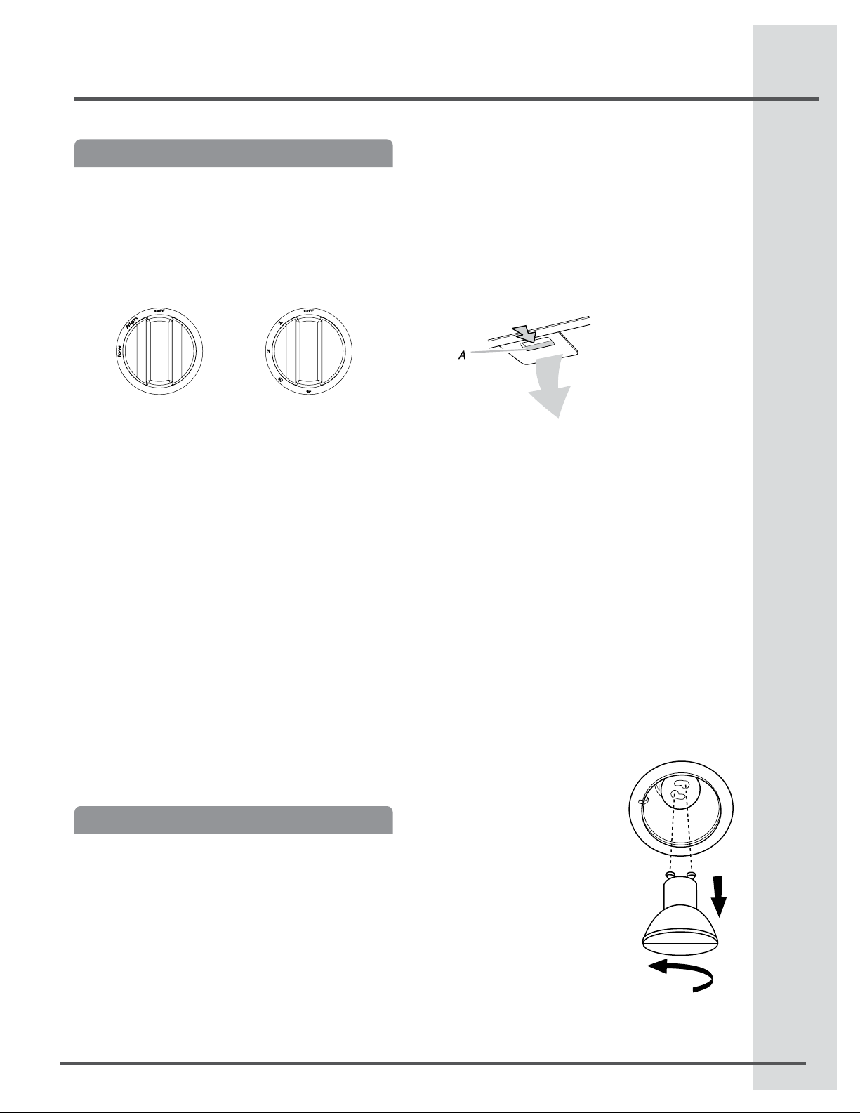
The hood controls are located on the underside of the
hood insert.
Light control Fan control
Operating the light
Turn the light switch (A) to the left 1 position for HIGH.
Turn the light switch (A) to the left 2 postions for LOW.
To turn the lights OFF, rotate the light switch (A) to the
right to the OFF position.
Operating the fan
The fan has 4 speeds. Rotate the fan switch (B) to
the left to turn the fan to the ON position. Continue to
rotate the switch to the desired fan speed.
To turn the fan OFF, rotate the fan speed (B) switch to
the right to the OFF position.
WARNING: The internal blower motor of the hood is
thermally protected against high temperatures.
If the hood insert is not turned on during the cooking
process, high temperatures could be present inside
the hood and the motor could not work until the temperature is safe. The hood insert should be
turned on during cooking operations.
Cleaning
IMPORTANT: Clean the hood insert and grease lters
frequently according to the following instructions. Replace grease lters before operating hood insert.
Exterior Surfaces:
To avoid damage to the exterior surface, do not use
steel wool or soap-lled scouring pads.
Always wipe dry to avoid water marks.
Cleaning Method:
Liquid detergent soap and water, or all-purpose
•
cleaner.
Wipe with damp soft cloth or nonabrasive sponge,
•
then rinse with clean water and wipe dry.
Metal Grease Filter:
Remove each lter by pulling the spring release
1.
handle and then pulling down the lter.
Wash metal lters as needed in dishwasher or hot
2.
detergent solution.
Reinstall the lter by making sure the spring
3.
release handles are toward the front. Insert
aluminum lter into upper track.
Push in spring release handle.
4.
Push up on metal lter and release handle to latch
5.
into place.
Repeat steps 1-5 for the other lter.
6.
Replacing the Halogen Lamps
Turn off the hood insert and allow the halogen lamp
to cool. To avoid damage or decreasing the life of the
new bulb, do not touch bulb with bare ngers. Replace bulb, using tissue or wearing cotton gloves to
handle bulb.
If new lamps do not operate, make sure the lamps are
inserted correctly before calling service.
Disconnect power.
1.
Push up on the lens and turn
2.
it counterclockwise.
Remove the bulb and replace
3.
it with a 120-volt, 50-watt
maximum halogen bulb with a
GU10 base. Turn it clockwise
to lock it into place.
Repeat steps 2-3 for the other
4.
bulb if needed.
Reconnect power.
5.
A.Spring release handle
Page 16

16
Warranty Information
Your appliance is covered by a one year limited warranty. For one year from your original date of purchase, Electrolux will pay
all costs for repairing or replacing any parts of this appliance that prove to be defective in materials or workmanship when
such appliance is installed, used and maintained in accordance with the provided instructions.
Exclusions This warranty does not cover the following:
1. Products with original serial numbers that have been removed, altered or cannot be readily determined.
2. Product that has been transferred from its original owner to another party or removed outside the USA
or Canada.
3. Rust on the interior or exterior of the unit.
4. Products purchased “as-is” are not covered by this warranty.
5. Food loss due to any refrigerator or freezer failures.
6. Products used in a commercial setting.
7. Service calls which do not involve malfunction or defects in materials or workmanship, or for appliances
not in ordinary household use or used other than in accordance with the provided instructions.
8. Service calls to correct the installation of your appliance or to instruct you how to use your appliance.
9. Expenses for making the appliance accessible for servicing, such as removal of trim, cupboards,
shelves, etc., which are not a part of the appliance when it is shipped from the factory.
10. Service calls to repair or replace appliance light bulbs, air lters, water lters, other consumables, or
knobs, handles, or other cosmetic parts.
11. Surcharges including, but not limited to, any after hour, weekend, or holiday service calls, tolls, ferry trip
charges, or mileage expense for service calls to remote areas, including the state of Alaska.
12. Damages to the nish of appliance or home incurred during installation, including but not limited to
doors, cabinets, walls, etc.
13. Damages caused by: services performed by unauthorized service companies; use of parts other than
genuine Electrolux parts or parts obtained from persons other than authorized service companies; or
external causes such as abuse, misuse, inadequate power supply, accidents, res, or acts of God.
DISCLAIMER OF IMPLIED WARRANTIES; LIMITATION OF REMEDIES CUSTOMER’S SOLE AND
EXCLUSIVE REMEDY UNDER THIS LIMITED WARRANTY SHALL BE PRODUCT REPAIR OR
REPLACEMENT AS PROVIDED HEREIN. CLAIMS BASED ON IMPLIED WARRANTIES, INCLUDING
WARRANTIES OF MERCHANTABILITY OR FITNESS FOR A PARTICULAR PURPOSE, ARE LIMITED TO
ONE YEAR OR THE SHORTEST PERIOD ALLOWED BY LAW, BUT NOT LESS THAN ONE YEAR.
ELECTROLUX SHALL NOT BE LIABLE FOR CONSEQUENTIAL OR INCIDENTAL DAMAGES SUCH AS
PROPERTY DAMAGE AND INCIDENTAL EXPENSES RESULTING FROM ANY BREACH OF THIS
WRITTEN LIMITED WARRANTY OR ANY IMPLIED WARRANTY. SOME STATES AND PROVINCES DO
NOT ALLOW THE EXCLUSION OR LIMITATION OF INCIDENTAL OR CONSEQUENTIAL DAMAGES, OR
LIMITATIONS ON THE DURATION OF IMPLIED WARRANTIES, SO THESE LIMITATIONS OR
EXCLUSIONS MAY NOT APPLY TO YOU. THIS WRITTEN WARRANTY GIVES YOU SPECIFIC LEGAL
RIGHTS. YOU MAY ALSO HAVE OTHER RIGHTS THAT VARY FROM STATE TO STATE.
If You Need Keep your receipt, delivery slip, or some other appropriate payment record to establish the warranty period
Service should service be required. If service is performed, it is in your best interest to obtain and keep all receipts.
Service under this warranty must be obtained by contacting Electrolux at the addresses or phone numbers
below.
This warranty only applies in the USA and Canada. In the USA, your appliance is warranted by Electrolux Major Appliances
North America, a division of Electrolux Home Products, Inc. In Canada, your appliance is warranted by Electrolux Canada
Corp.
Electrolux authorizes no person to change or add to any obligations under this warranty. Obligations for service and parts
under this warranty must be performed by Electrolux or an authorized service company. Product features or specications
as described or illustrated are subject to change without notice.
USA
1.282.622.373
Electrolux Major Appliances
North America
10200 David Taylor Drive
Charlotte, NC 28262
Canada
1.800.265.8352
Electrolux Canada Corp.
5855 Terry Fox Way
Mississauga, Ontario, Canada
L5V 3E4
Page 17

Trouver l’information
Lisez ces instructions et conservez-les
Merci d’avoir choisi Electrolux, le nouveau premier brand pour les appareils domestiques. Ce Guide
d’Utilisation et d’Entretien fait partie de notre engagement pour la satisfaction du client et la qualité du produit
à travers un service d’assistance pour votre nouvel appareil.
Votre achat est le début de notre relation. Pour nous assurer de continuer à bien vous servir, utiliser cette
page pour enregistrer des informations produit importantes.
Garder une trace pour trouver rapidement une référence.
17
Date d’achat
Numéro modèle Electrolux
Numéro de série Electrolux
Enregistrer votre produit avec Electrolux nous permet
de mieux vous servir. Vous pouvez vous enregistrer
sur www.electroluxappliances.com ou en envoyant
votre Carte d’Enregistrement Produit par courrier.
REMARQUE
Des Questions?
Pour assistance téléphonique aux U.S. et Canada:
US.: 1.800.944.9044 / Canada: 1.800.265.8352
Pour support online et information produit sur Internet, visiter http:// www.electroluxappliances.com
Table des matières
Avis de sécurité important................................... 18
Outils et pièces...................................................... 21
Spécifications électriques.................................... 21
Exigences d’emplacement................................... 22
Dimensions du produit ......................................... 22
Exigences concernant l’évacuation................... 23
Méthodes d’évacuation................................................. 23
Installation du moteur interne
a la hotte intégrée.................................................. 24
Installation du moteur remote
a la hotte intégrée.................................................. 26
Réalisation des connexions électriques
du Motor Remote Systeme.................................. 27
Préparation de l’emplacement............................ 29
Réalisation des connexions de l’alimentation
électrique à la caisse de la hotte......................... 30
Achever l’installation et vérier
le fonctionnement.................................................. 31
Utilisation de la hotte.............................................31
Nettoyage................................................................ 32
Informations sur la garantie................................. 33
Page 18

18
Avis de sécurité important
Avis de sécurité important
Lire toutes les instructions avant
d’utiliser l’appareil.
Conserver ces instructions pour une
future consultation.
Approuvé comme appareil domestique.
Pour usage résidentiel uniquement.
Ne pas essayer d’installer ou d’utiliser votre appareil
si vous n’avez pas lu les instructions de sécurité de
ce manuel. Les particularités de sécurité de ce
manuel sont marqués d’ un AVERTISSEMENT ou
ATTENTION selon le type de risque.
Ce symbole vous avertit de situations pouvant
causer de graves lésions corporelles, la mort ou
un dommage matériel.
Ce symbole vous avertit de situations pouvant
causer des blessures corporelles ou des dégâts
matériels.
VEUILLEZ LIRE CES INSTRUCTIONS AU COMPLET AVANT DE COMMENCER.
L’INSTALLATION DE L’APPAREIL DOIT RESPECTER TOUS LES CODES EN VIGUEUR.
IMPORTANT : Conservez ces instructions an de pouvoir les remettre à l’inspecteur-électricien de votre
région.
INSTALLATEUR : Veuillez laisser ces instructions avec l’appareil pour le propriétaire.
PROPRIÉTAIRE : Veuillez conserver ces instructions pour pouvoir vous y référer plus tard.
Avertissement de sécurité : Coupez l’alimentation du circuit dans le panneau électrique et verrouillez le
panneau avant de raccorder les ls de cet appareil.
Exigence : 120 V c.a., 60 Hz circuit de dérivation de 15 V c.a., 20 Hz, de 15 ou 20 A.
Page 19

Avis de sécurité important
LISEZ CES INSTRUCTIONS ET CONSERVEZ-LES
Avis de sécurité important
19
UTILISER CET APPAREIL À DES FINS DE VENTILATION
GÉNÉRALE SEULEMENT. NE PAS UTILISER CET
APPAREIL POUR ÉVACUER DES MATÉRIAUX OU DES
VAPEURS DANGEREUX OU EXPLOSIFS.
POUR RÉDUIRE LES RISQUES D’INCENDIE, DE
CHOC ÉLECTRIQUE ET DE BLESSURE,
RESPECTER LES DIRECTIVES SUIVANTES:
Utiliser cet appareil uniquement aux ns prévues
A.
par le fabricant. Si vous avez des questions à propos
de l’appareil, communiquez avec le fabricant.
Avant de faire l’entretien de l’appareil ou de le nettoyer,
B.
coupez l’alimentation dans le panneau électrique et
verrouillez le panneau en bloquant le dispositif
permettant d’empêcher d’activer l’alimentation
accidentellement. S’il n’est pas possible de verrouiller
l’accès au panneau, xez une étiquette très voyante au
panneau électrique.
Une personne qualiée doit effectuer l’installation
C.
et le câblage des ls électriques en conformité
avec tous les codes et toutes les normes, y compris la
cote de résistance au feu.
Il est important de prévoir sufsamment d’air pour
D.
assurer une bonne combustion de l’équipement
de chauffe et l’évacuation adéquates des gaz par
le conduit de cheminé an de prévenir les refoulements
d’air. Respectez les directives et les normes de sécurité
des fabricants de l’équipement de chauffage, comme
celles publiées par la National Fire Protection
Association (NFPA), la American Society for Heating,
Refrigeration and Air Conditioning Engineers (ASHRAE)
et le code des autorités de votre région.
Au moment de couper ou de percer un mur ou
E.
un plafond, assurez-vous de ne pas endommager
la lerie électrique ou tout autre accès à un
service publique.
Il faut toujours évacuer à l’extérieur les systèmes
F.
à conduit.
Pour réduire les risques d’incendie et évacuer l’air
correctement, assurez-vous que le conduit mène à
l’extérieur; il ne faut pas évacuer l’air dans l’espace entre
les murs, dans les plafonds, dans les greniers, les vides
sanitaires ou les garages.
POUR RÉDUIRE DES RISQUES D’INCENDIE, UTILISEZ
UNIQUEMENT DES CONDUITS EN MÉTAL.
Installez cette hotte en respectant toutes les exigences
mentionnées.
Pour réduire les risques d’incendie et de choc électrique,
n’utilisez pas cette hotte avec un contrôleur de vitesse à
semi-conducteurs.
POUR RÉDUIRE LES RISQUES D’INCENDIE DE GRAISSE
SUR LES CUISINIÈRES.
Ne laissez jamais la cuisinière sans surveillance
a)
lorsqu’elle est réglée à une haute température.
Les débordements par bouillonnement causent de la
fumée et des débordements de gras qui peuvent
s’enammer. Faites chauffer l’huile lentement, à une
température basse ou moyenne.
Faites toujours fonctionner la hotte lorsque vous
b)
utilisez la cuisinière à une haute température ou que
vous faites amber des aliments (P. ex.: crêpes Suzette,
cerises jubilées, boeuf au poivre ambé).
Nettoyez les hélices de ventilation fréquemment. Il ne
c)
faut pas que la graisse s’accumule sur les lres ou les
hélices.
Utilisez le bon format de casserole. Utilisez toujours un
d)
chaudron de taille approprié à l’élément de la cuisinière.
Page 20

20
Avis de sécurité important
POUR ÉVITER DE BLESSER QUELQU’UN LORS
D’UN INCENDIE DE GRAISSE SUR LA CUISINIÈRE,
SUIVRE LES CONSEILS SUIVANTS :
ÉTOUFFER LES FLAMMES avec un couvercle aux
a)
dimensions de la taque de cuisson, une tôle à biscuit ou
tout autre plateau métallique, puis couper le gaz ou
l’alimentation électrique de la cuisinière. FAIRE
ATTENTION A NE PAS SE BRÛLER. Si les ammes ne
s’éteignent pas immédiatement, QUITTER LA PIÈCE ET
APPELER LES POMPIERS.
NE JAMAIS PRENDRE EN MAIN UNE CASSEROLE
b)
EN FEU, vous pourriez vous blesser.
NE PAS UTILISER D’EAU, y compris les essuies
c)
de vaisselle ou les serviettes humides – une violente
explosion due à la vapeur formée pourrait survenir.
Utiliser un extincteur SEULEMENT si :
d)
Vous êtes sûr d’avoir un extincteur de classe
1)
ABC que vous savez utiliser.
Le feu est petit et conné à la zone où il s’est
2)
formé.
Les pompiers ont été appelés.
3)
Vous pouvez lutter contre le feu avec une
4)
sortie derrière vous.
MODE OPÉRATOIRE
Toujours laisser les grilles de sécurité et les ltres à leur
place. Sans la présence de ces derniers, les parties aspirantes pourraient attirer les cheveux, les doigts ou les vêtements.
Le fabricant décline toute responsabilité si les informations
détaillées dans ce manuel pour l’installation, l’entretien et
l’utilisation adéquate du produit ne sont pas observées.
Le fabriquant décline en outre toute responsabilité pour
d’éventuelles blessures dues à des négligences; en outre,
la garantie de l’appareil sera annulée suite à des conditions
d’entretien inappropriées. Cet appareil est fabriqué pour un
usage interne. Ne pas utiliser cet appareil à l’extérieur.
Page 21

Outils et pièces- Spécications électriques
21
Outils et Pièces
Pièces fournies
Filtres à graisse métalliques:
•
- Modèle EI30HI55KS: 2 ltres
- Modèle EI36HI55KS: 3 ltres
- Modèle EI48HI55KS: 4 ltres
Caisse de la hotte avec lampes à halogène installées.
•
1 - raccord de conduit carré de 10” (25,4 cm) à
•
rond de 10” (25,4 cm) avec clapet anti-retour.
4 - vis de montage de 5 x 45 mm
•
4 - vis de montage de 4.2 x 8 mm
•
2 - 18 mm entretoise vis (uniquement pour
•
EI30HI55KS modèle).
Pièces nécessaires
Câble d’alimentation électrique du domicile
•
1 serre-câble de ½” (1,3 cm) (homologation UL ou CSA)
•
3 connecteurs de ls homologués UL
•
1 bouche de décharge (décharge à travers le mur
•
ou à travers le toit)
Circuit d’évacuation métallique
•
Système du moteur du ventilateur — interne ou
•
remote (voir “Options du système moteur ”).
Outils nécessaires
Niveau
•
Perceuse
•
Foret de 1¼” (3 cm)
•
Foret de 1/8” (3 mm)
•
Crayon
•
Pince à dénuder ou
•
couteau utilitaire
Mètre-ruban ou règle
•
Pince
•
Options du système moteur
(1 système est nécessaire pour la hotte)
Options du systeme moteur HOTTE DE LA CUISINIERE MODELES
MODELES RATING
EI06HIPIKS
(600 cfm Int. Moteur Kit)
EI12HIPIKS
(1200 cfm Int. Moteur Kit)
EI06HIPRKS
(600 cfm Remote Moteur Kit)
EI12HIPRKS
(1200 cfm Remote Moteur Kit)
Vous pouvez utiliser le modèle de votre hotte de cuisinière avec ce kit
moteur du ventilateur.
3.7 A
7.4 A
3.7 A
7.4 A
Pistolet à calfeutrage
•
et composé de
calfeutrage résistant
aux intempéries
Brides de conduit
•
Scie sauteuse ou scie
•
à guichet
Tournevis à lame plate
•
Cisaille de ferblantier
•
Tournevis Phillips
•
EI30HI55K5 EI36HI55K5 EI48HI55K5
• • •
• •
• • •
• • •
Spécications électriques
Observer les dispositions de tous les codes et
règlements en vigueur.
Vérier que l’installation électrique a été correctement
effectuée et qu’elle est conforme aux spécications
de la plus récente édition des normes National Electrical Code, ANSI/NFPA 70, ou de la norme CSA C22.194, Code canadien de l’électricité, partie 1 et C22.2 N°
0-M91 (dernière édition) et de tous les codes et
règlements en vigueur locaux.
Si les codes le permettent et si on utilise un conducteur
distinct de liaison à la terre, il est recommandé qu’un
électricien qualié vérie la qualité de la liaison à la terre.
Pour obtenir un exemplaire de la norme des codes
ci-dessus, contacter:
National Fire Protection Association
One Batterymarch Park
Quincy, MA 02269
CSA International
8501 East Pleasant Valley Road
Cleveland, OH 44131-5575
L’appareil doit être alimenté par un circuit de 120
•
V, CA seulement, 60 Hz, 15 A, protégé par fusible.
Si le domicile est équipé d’un câblage en
•
aluminium, suivre les instructions suivantes :
Connecter une section de câble en cuivre
1.
massif aux conducteurs en queue de cochon.
Connecter le câblage en aluminium à la
2.
section ajoutée de câblage en cuivre en
utilisant des connecteurs et/ou des outils
spécialement conçus et homologués UL pour
xer le cuivre à l’aluminium.
Appliquer la procédure recommandée par le fabricant
des connecteurs. La connexion aluminium/cuivre doit
être conforme aux codes locaux et aux pratiques de
câblage acceptées par l’industrie.
Le calibre des conducteurs et les connexions
•
doivent être compatibles avec la demande de
courant de l’appareil spéciée sur la plaque
signalétique. La plaque signalétique de l’appareil
est située derrière le filtre, sur la paroi arrière de la hotte.
Le calibre des conducteurs doit satisfaire aux
•
exigences de la plus récente édition de la norme
National Electrical Code, ANSI/NFPA 70, ou de la
norme CSA C22.1-94, Code canadien de
l’électricité, partie 1 et C22.2 n° 0-M91 (dernière
édition) et de tous les codes et règlements en vigueur.
ATENTTION
Pour réduire le risque d’incendie ou de choc électrique, installez cette hotte uniquement avec les
modèles de moteurs internes et remote avec une
capacité de 7.4 A (Electrolux™).
Page 22

22
Exigences d’emplacement
Exigences d’emplacement
IMPORTANT: Observer les dispositions de tous les
codes et règlements en vigueur.
Demander à un technicien qualié d’installer la caisse
de la hotte. C’est à l’installateur qu’incombe la responsabilité de respecter les distances de séparation
spéciées sur la plaque signalétique de l’appareil. La
plaque signalétique de l’appareil est située derrière le
ltre de gauche, sur la paroi arrière de caisse de hotte.
La caisse de la hotte doit être installée à l’écart de
houte zone exposée à des courants d’air, comme des
fenêtres, des portes et bouches de chauffage à fort
débit.
Respecter les dimensions indiquées pour les ouvertures à découper dans les placards. Ces dimensions
tiennent compte des valeurs minimales des dégagements de séparation.
La caisse de la hotte doit se trouver dans un enceinte
construite sur mesure avec un support de hotte capable de soutenir une charge de 75 lb (34 kg).
On doit disposer d’une prise de courant électrique
reliée à la terre. Voir la section “Spécications électriques”.
On doit assurer l’étanchéité au niveau de chaque
ouverture découpée dans le plafond ou un mur
traversé par l’équipement de la hotte.
Installation dans une résidence mobile
L’installation de cette hotte doit satisfaire aux exigences de la norme Manufactured Home Construction
Safety Standards, Titre 24 CFR, partie 328 (anci-
ennement Federal Standard for Mobile Home Construction and Safety, titre 24, HUD, partie 280); lorsque
cette norme n’est pas applicable, l’installation doit
satisfaire aux critères de la plus récente édition de la
norme Manufactured Home Installation 1982 (Manufactured Home Sites, Communities and Setups) ANSI
A225.1/NFPA 501A, ou des codes locaux.
Dimensions du placard
30” (76.2 cm) Modèle 30”
36” (91.4 cm) Modèle 36”
48” (121.9 cm) Modèle 48”
Le support de la hotte
doit être capable de soutenir
une charge de 75 lb (34 kg)
Distance “X” entre le bas
du auvent et la surface de cuisson
Profondeur
de la caisse
de hotte
22” (55.9 cm)
IMPORTANT:
Valeur minimale de la distance “X” : 24” (61 cm) à partir des
surfaces de cuisson électriques.
Valeur minimale de la distance “X” : 30” (76,2 cm) à partir des
surfaces de cuisson au gaz.
Valeur maximale suggérée pour la distance “X” : 36” (91,4 cm)
Dimensions du produit
modèles de 36” et 48”
sortie de câblage
8”
(31.4 cm)
16
” (12.2 cm)
(29.2 cm)
16”
(12.8 cm)
271/2”(70 cm) modèles 36 et 48”
245/16 (61.8cm) Modèles 30”
30” (75.8 cm)
30” (76.2 cm) Modèle 30”
36” (91.4 cm) Modèle 36”
48” (121.4 cm) Modèle 48”
22” (56 cm)modèle 30”
Modèles 36 et 48”
97/8” (25.11 cm)
15” (38 cm) Modèle 30”
18” (45.2 cm) Modèle 36”
24” (61 cm) Modèle 48”
modèle de 30”
sortie de câblage
11” (28 cm)
10 1/8” (
11” (28 cm) pour le modèle 30”
25.7 cm) pour les modèles 36 & 48”
22” (55.9 cm)
Page 23

Exigences concernant l’évacuation
Le système doit décharger l’air à l’extérieur.
•
Ne pas terminer le circuit d’évacuation dans un
•
grenier ou dans un autre espace clos.
Ne pas utiliser une bouche de décharge murale de
•
4” (10,2 cm) normalement utilisée pour un
équipement de buanderie.
Utiliser un conduit métallique uniquement. Un
•
conduit en métal rigide est recommandé. Ne pas
utiliser de conduit de plastique ou en aluminium.
La longueur du système d’évacuation et le
•
nombre de coudes doit être réduit au minimum
pour des performances optimales.
Pour un fonctionnement efcace et silencieux:
Ne pas utiliser plus de trois coudes à 90°.
•
Veiller à ce qu’il y ait une section droite de
•
conduit d’un minimum de 24” (61 cm) entre les
raccords coudés, si on doit en utiliser plus d’un.
Ne pas installer 2 coudes successifs.
•
Au niveau de chaque jointure du circuit
•
d’évacuation, assurer l’étanchéité avec les brides
de serrage, et utiliser du ruban adhésif pour sceller
complètement les connexions.
À l’aide d’un produit de calfeutrage, assurer
•
l’étanchéité autour de la bouche de décharge à
l’extérieur (à travers le mur ou le toit).
La taille du conduit doit être uniforme.
•
Installations pour régions à climat froid
On doit installer un clapet anti-retour supplémentaire
à l’arrière pour minimiser le reux d’air froid dans le
cadre du système de ventilation.
Incorporer un élément d’isolation thermique pour
minimiser la conduction de chaleur par l’intermédiaire
du conduit d’évacuation, de l’intérieur de la maison à
l’extérieur dans le cadre du système de ventilation.
Le clapet anti-retour doit être placé du côté air froid de
la résistance thermique.
L’élément d’isolation thermique doit être aussi proche
que possible de l’endroit où le circuit d’évacuation
s’introduit dans la partie chauffée de la maison.
Air d’appoint
Les codes locaux en bâtiment peuvent imposer
l’emploi d’un circuit de renouvellement de l’air/introduction d’air d’appoint, lors de l’utilisation d’un circuit
d’aspiration de débit supérieur à une valeur spéciée
en pieds cubes par minute. Le débit spécié en pieds
cubes par minute varie d’une juridiction à l’autre.
Consulter un professionnel des installations de
chauffage ventilation/climatisation au sujet des
Exigences de Ventilation
exigences spéciques applicables dans la juridiction
locale.
Méthodes d’évacuation
L’ouverture de sortie de la hotte a un diamètre de 10 “.
•
Dans les installations utilisant le Système moteurs
•
600 CFM est recommandé d’utiliser un système
de ventilation de 6” ou 8”.
Dans les installations utilisant le Système moteur
•
de 600 CFM doit utiliser un système de ventilation
de 10”.
Vous pouvez utiliser un plus petit système de
•
refroidissement, mais va générer un niveau de bruit.
REMARQUE: évent exible n’est pas recommandée.
Évent exible crée une contre-pression et l’air
turbulences qui réduisent considérablement les
performances. Système de ventilation peut résilier
ce soit à travers la toit ou le mur. Pour ventilation
dans le mur, un coude à 90 ° est nécessaire.
Décharge à travers le toit
B
A
A. Conduit circulaire de 10” (25,4 cm)
B. Bouche de décharge sur toit
Typique Installations du système de ventilation
par moteur externe
B
A
A. Conduit circulaire de 10” (25,4 cm)
B. Montage au-dessus des solives.
D. Contreplaqué (facultatif pour certaines installations)
G. Conduit horizontal, montage sur traverses de ferme.
C. Bouches de décharge sur toit
F. Montage sur traverses de ferme.
H. Bouche de décharge murale
C
D
A
E.Montage sous les chevrons.
Évacuation par le mur
A
A. Conduit circulaire de 10” (25,4 cm)
B. Bouche de décharge murale
D
A
E
F
G
H
23
B
A
Page 24

24
Installation des Systèmes Moteurs
Installation du moteur interne a
la hotte intégrée
Le système de ventilation interne peut être monté pour
une évacuation par le dessus. Pour la ventilation par
le dessus, le support de montage et l’attache à ressort
fournis avec le système de ventilation seront montées
sur le panneau supérieur de la caisse de la hotte.
Installation du moteur interne a la hotte intégrée
IMPORTANT: Exécuter les étapes 1 à 10 avant de
monter la caisse de la hotte de cuisinière.
REMARQUE: Le matériel de montage est inclus avec
le système moteur.
1.
Retirer les ltres à graisse de la caisse de la
hotte. Voir la section “Nettoyage” du guide
d’utilisation et d’entretien.
2.
Monter le support du moteur à l’aide des trois vis
de 4,2 x 8 mm. Visser le support à l’intérieur au
sommet, du côté gauche de la caisse de la hotte
(voir la gure à l’étape 2).
3.
Installer la languette à ressort du moteur à l’aide
des deux vis de 4,2 x 8 mm. Visser la languette
à ressort à l’intérieur au sommet de la caisse de la
hotte, à l’endroit correct selon le système de mo teur sélectionné. Glisser la patte de montage de la
languette à ressort par la fente dans le panneau et
la xer à l’aide des vis. (voir la gure à l’étape 3).
Sur le hotte Sur le hotte
Dans la hotte Dans la hotte
ÉTAPE 2 ÉTAPE 3
F*
A
A. 3 vis de 4,2 x 8 mm pour le
support du moteur
B. 2 vis de 4,2 x 8 mm pour la
languette à ressort du moteur
C. Support de montage du
moteur
C
D
E
D. Languette à ressort du moteur
(emplacement pour système à un seul
ventilateur)
E. Languette à ressort du moteur
(emplacement pour système à deux
ventilateurs)
B
Fixer les écrous de 6 mm à l’extérieur de la hotte,
4.
en haut ou à l’arrière (autre emplacement sur certains
modèles) de la caisse de la hotte, à l’endroit correct
selon le système de ventilation sélectionné.
Deux écrous de 6 mm sont nécessaires pour
•
le système à un seul ventilateur de 600 CFM.
Emboîter les écrous dans les petites encoches
carrées situées à droite et à gauche de l’ouverture
d’évacuation carrée.
Quatre écrous de 6 mm sont nécessaires
•
pour le système à deux ventilateurs de 1200 CFM.
Emboîter les écrous dans les petites encoches
carrées, l’une située à l’avant de l’ouverture
d’évacuation carrée et les quatre autres à gauche
et à droite de l’ouverture d’évacuation carrée.
A. 6mm écrous
B.Emplacement des écrous à emboîter pour le
système à un seul ventilateur (quantité 2)
C. Emplacement des écrous à emboîter pour le
système à deux ventilateurs (quantité 4)
A
C
Installer le moteur du ventilateur de la caisse de la
5.
hotte à l’intérieur de l’auvent de la caisse,
B
connexion du câblage à gauche pour le système
à ventilateur unique et à l’avant ou au-dessus pour
le système à deux ventilateurs.
Assemblage du moteur simple
A
A.connexion des câbles
C
Page 25

Assemblage du moteur dual
A.connexion des câbles
A
Pour installer le système moteur, glisser le rebord
6.
gauche de la plaque de montage sous le support
de montage du moteur.
A
Pousser l’extrémité de droite de la plaque de
7.
montage du moteur et l’enclencher dans la
languette à ressort.
B
A. Support de montage du moteur
B. Rebord gauche de la plaque de montage
REMARQUE : La languette à ressort doit être à
l’extérieur de la fente de la plaque de montage.
A
B
A. Plaque de montage du moteur
B. Languette à ressort
Installation des Systèmes Moteurs
Faire correspondre les trous de la plaque de
8.
montage du moteur avec les écrous à emboîter
servant à xer le moteur et installer les vis de
6 x 16 mm et les rondelles-freins de 6,4 mm
A
A. Bolt with lock washer
B. Mounting hole
B
Relier le connecteur du cordon d’alimentation de
9.
la hotte au connecteur du boîtier de connexion..
A. Connecteur du boîtier
de connexion
B. Connecteur du cordon
d’alimentation de la hotte
Instalez raccord de conduit rond de 10” avec 4 à
10.
A
B
4,2 x 8 mm vis de montage.
A
BB
Continuer à préparer l’emplacement à la page 29.
11.
A.Raccord de conduit rond de 10”
(25,4 cm) avec clapet anti-retour.
B. Vis de montage
25
Page 26

26
Installation des Systèmes Moteurs
Installation du moteur remote
a la hotte intégrée
Preparation du montage du systeme de ventilation
à distance
Le systeme de ventilation à distance doit etre xe a
une structure securisee de la toiture, du plafond, mur,
sol, ou une nouvelle charpente ou une charpente
preexistante. Les 4 trous sur l’entree (bas) ou la sortie
(haut) du ventilateur doivent etre utilises pour monter le
systeme de ventilation à distance a la structure.
REMARQUE: Les emplacements des trous de montage doivent traverser les poteaux de colombage.
Des pans a colombage supplementaires pourraient
s’averer necessaires. Il est possible d’utiliser du contre-plaque pour couvrir les zones qui se trouvent entre
les solives de plafond ou les chevrons du toit an de
faciliter l’installation. Cette structure doit etre sufsamment solide pour supporter le poids du systeme de
ventilation à distance (50 lb [22,6 kg] min).
Preparation du systeme de ventilation à distance
Risque du poids excessif
Utiliser deux ou plus de personnes pour déplacer
et installer la hotte de la cuisinière.
Le non-respect de cette instruction peut causer
une blessure au dos ou d’autre blessure.
Tirer sur la languette a resort pour degager
3.
l’ensemble moteur-ventilateur. Retirer l’ensemble
moteur-ventilateur du carter et le placer sur une
surface couverte.
A. Couvercle avant
B. Vis de montage du
ventilateur
C. Languette à ressort
A
D. Trous de montage du carter
inférieur
E. Fiche électrique du moteur
B
C
D
Installation du moteur remote
REMARQUE: Le boîtier moteur du ventilateur peut être
monté l’aide de 4 trous soit du côté de l’entrée ou la
sortie de la souferie
A
A
Côté entrée
A l’aide d’au moins 2 personnes, deplacer le
1.
systeme du moteur du ventilateur à distance
jusqu’a l’emplacement de montage.
Enlever les 10 vis du couvercle avant du carter du
2.
moteur du ventilateur à distance et les mettre de
cote.
Enlever le couvercle avant du carter du moteur du
3.
ventilateur à distance et le mettre de cote.
REMARQUE: L’ensemble moteur-ventilateur peut etre
retire pour faciliter le montage du carter du moteur du
ventilateur. Si l’on ne souhaite pas retirer l’ensemble
moteur-ventilateur, passer a “Installation du systeme
de ventilation à distance” dans cette section.
Pour déconnecter le système moteur
Debrancher la prise electrique du moteur de
1.
l’ensemble moteur-ventilateur.
Enlever les vis qui xent l’ensemble moteur-
2.
ventilateur au carter du ventilateur à distance et
découpage nécessaires pour le passage du circuit
d’évacuation les mettre de cote.
A. Trous de montage
A
A
Côté de la sortie
Positionner le carter du moteur du ventilateur dans
1.
son emplacement de montage et marquer les
emplacements des 4 trous de montage.
A
A
Page 27

Percer 4 avant-trous a l’aide d’un foret de 3” (5mm).
2.
Fixer le carter du moteur du ventilateur à distance à
3.
l’emplacement de montage avec quatre vis de
montage et rondelles 6 x 80 mm.
Réinstaller l’ensemble moteur-ventilateur s’il a été
4.
enlevé et le xer avec les vis enlevées
précédemment.
Achever la préparation
Déterminer et marquer toutes les lignes de
1.
découpage nécessaires pour le passage du circuit
d’évacuation.
IMPORTANT: Lors des opérations de découpage et
de perçage dans un mur ou un plafond, veiller à ne
pas endommager les câblages électriques ou canalisations qui peuvent s’y trouver.
Déterminer l’emplacement de passage du conduit
2.
de câblage de ¹⁄
le mur entre le ventilateur à distance et la caisse
2” (1,3 cm) à travers le plafond ou
de la hotte.
Percer un trou de 1¹⁄4” (3,2 cm) à cet endroit.
3.
Localiser les boîtiers de connexion dans le carter
4.
du ventilateur à distance et la caisse de la hotte.
Retirer les couvercles du boîtier de connexion et
les mettre de côté avec les vis.
B
A
A. Boîtier de connexion
B.Opercule arrachable
Retirer l’opercule arrachable du carter du
5.
ventilateur à distance et de la caisse de hotte an
de préparer l’installation du conduit de câblage de
¹⁄
2” (1,3 cm) et de son connecteur (homologation
UL ou CSA).
REMARQUE: Le serre-câble sont fournies avec le
matériel du remote moteur.
Une fois la caisse de hotte montée, (voir la section
6.
“Installation de la caisse de la hotte”), acheminer
le conduit de câblage de ¹⁄
2” (1,3 cm) entre le
carter du moteur du ventilateur à distance et la
caisse de la hotte. Tirer sufsamment de conduit
de câblage de ¹⁄
2” (1,3 cm) pour permettre un
raccordement facile aux boîtiers de connexion du
carter du ventilateur à distance et celui de la
caissede la hotte.
Installation des Systèmes Moteurs
Faire passer les six conducteurs de calibre 18
7.
AWG à travers le conduit de câblage de ¹⁄
cm) et les connecteurs de conduit et dans les
boîtiers de connexion du carter du ventilateur à
distance et celui de la caisse de la hotte. Laisser
sufsamment de longueur de câble dans chaque
boîtier de connexion an de réaliser les
connexions de câblage.
Installer les connecteurs du conduit et le conduit
8.
dans le boîtier de connexion du ventilateur en
ligne et celui de la caisse de la hotte.
REMARQUE: Le serre-câble sont fournies avec le
matériel du remote moteur.
Raccorder le circuit d’évacuation à la caisse de
9.
hotte et au système de ventilation interne et assurer
l’étanchéité de tous les raccords avec des colliers.
A
B
E
C
D
F
G
A. Système de ventilation
B. Moteur Remote
C. Plafond
D. Chevrons / contreplaqué
E. Conduit de câblage Moteur
Remote
F. Conduit de câblage du
Hotte Integré
G. Hotte Integré
Réalisation des connexions électriques du Motor
Remote Systeme
Risque de choc électrique
Déconnecter la source de courant électrique avant
l’entretien.
Replacer pièces et panneaux avant de faire la
remise en marche.
Le non-respect de ces instructions peut causer
un décès ou un choc électrique.
Réalisation des connexions électriques au sein de
Motor Remote Systeme
Déconnecter la source de courant électrique.
1.
Connecter les ls du conduit de câblage aux ls
2.
de la che électrique du moteur qui se trouve à
l’intérieur du boîtier de connexion du carter du
ventilateur à distance.
2” (1,3
27
Page 28

28
Installation de la hotte
C
E
F
G
D
B
H
I
A. Conduit de câblage de ¹⁄2”
(1,3 cm) homologué UL ou CSA
B. Connecteurs de ls
(homologation UL)
C.Conducteurs noirs
D. Connecteurs blancs
Connecter ensemble les conducteurs noirs (C) à
3.
F. Conducteurs bleus
G. Conducteurs gris
H. Conducteur vert (ou jaune/
vert) et vert/jaune
I. Câble de la che électrique
du moteur
l’aide de connecteurs de ls (homologation UL)
Connecter ensemble les conducteurs blancs (D)
4.
à l’aide de connecteurs de ls (homologation UL).
Connecter ensemble les conducteurs rouges (E)
5.
à l’aide de connecteurs de ls (homologation UL).
Connecter ensemble les conducteurs bleus (F) à
6.
l’aide de connecteurs de ls (homologation UL).
Connecter ensemble les conducteurs gris (G) à
7.
l’aide de connecteurs de ls (homologation UL).
Risque de choc électrique
Relier le ventilateur à la terre.
Brancher le l relié à la terre au l vert et jaune
relié à la terre dans la boîte de la borne.
Le non-respect de ces instructions peut causer un
décès ou un choc électrique.
Connecter le conducteur vert (ou jaune/vert) de
8.
liaison à la terre au conducteur de terre (vert
jaune) (H) du boîtier de raccordement avec des
connecteurs de ls homologués UL.
Réinstaller le couvercle et les vis du boîtier de
9.
connexion du ventilateur à distance.
Réinstaller le couvercle avant du carter du ventila-
10.
teur à distance et le xer avec 10 vis de montage.
Connexion électrique à l’intérieur de la caisse de
hotte entre le système du ventilateur à distance et
la caisse de hotte
Une fois la caisse de la hotte montée (voir la
1.
section “Installation de la caisse de la hotte”),
rechercher le connecteur du câble à l’intérieur de
la caisse de la hotte.
Connecter l’ensemble de connexion à 6 ls fourni
2.
avec le système du moteur du ventilateur à
distance au connecteur du câble correspondant
dans la caisse de la hotte.
A
Repérer le boîtier de connexion à l’intérieur de la
3.
caisse de la hotte et installer un serre-câble
¹⁄
2” (1,3 cm) homologué UL ou CSA (voir “Achever
la préparation” dans la section “Préparation de
l’emplacement”).
Acheminer les extrémités des ls à parti de
4.
l’ensemble de connexion à 6 ls à travers le
serre-câble ¹⁄
2” (1,3 cm), en laissant sufsamment
de longueur pour effectuer les connexions de
câblage. Serrer les vis du serre-câble.
Connecter les ls de l’ensemble de connexion à 6
5.
ls aux ls du conduit de câblage qui se trouve à
l’intérieur du boîtier de connexion de la caisse de
la hotte.
Connecter les conducteurs de même couleur
6.
entre eux (noir à noir, blanc à blanc, etc.) en
utilisant des connecteurs de ls (homologation
UL).
REMARQUE : Connecter le conducteur vert (ou vert/
jaune) de liaison à la terre du conduit de câblage au
conducteur vert (ou nu) de liaison à la terre du câble
d’alimentation du domicile à l’aide de connecteurs de
ls homologués UL (voir la section “Réalisation des
connexions de l’alimentation électrique à la caisse de
la hotte”).
J K
B
A. Conduit de câblage de
¹⁄2” (1,3 cm) homologué UL ou CSA
B. Connecteurs de ls
(homologation UL)
C. Conducteurs noirs
D. Connecteurs blancs
E. Conducteurs rouges
A
F. Conducteurs bleus
G. Conducteurs gris
H. Conducteur vert (ou vert/jaune)
I. Ensemble de connexion à six ls
J. forage de installation
I
C
D
E
F
G
H
Page 29

l connecteur
Connexions de
câblage a terre
Passer à la section “Réalisation des connexions
7.
Home
Power Supply
Remote
Moteur
Hotte de la
cuisiniere
de l’alimentation électrique à la caisse de la
hotte”.
Préparation de l’emplacement
Préparation Initiale
Déconnecter la source de courant électrique.
1.
Déterminer la méthode d’évacuation à utiliser: à
2.
travers le toit ou à travers le mur.
Sélectionner une surface plane pour l’assemblage
3.
de la hotte. Placer le matériau de protection sur
cette surface.
Il est recommandé d’installer le conduit de décharge
•
avant de procéder à l’installation de la hotte.
Avant d’exécuter les découpages, vérier la
•
disponibilité d’un dégagement sufsant dans le
plafond ou le mur pour le conduit d’évacuation.
La caisse de la hotte doit être installée à 24” (61
•
cm) min. des surfaces de cuisson électriques, 30”
(76,2 cm) min. des surfaces de cuisson au gaz, et
à un maximum suggéré de 36” (91,4 cm) au-de
sus de la surface de cuisson.
Vérier que les pièces d’installation ont été retirées
•
du carton d’expédition.
À l’aide de deux personnes ou plus, soulever la
4.
caisse de la hotte et la poser sur la surface couverte.
RISQUE DU POIDS EXCESSIF
UTILISER DEUX OU PLUS DE PERSONNES
POUR DÉPLACER ET INSTALLER LA HOTTE DE LA
CUISINIÈRE.
LE NON-RESPECT DE CETTE INSTRUCTION
PEUT CAUSER UNE BLESSURE AU DOS OU
D’AUTRE BLESSURE.
Ôter les ltres. Voir la section “Entretien de la
5.
hotte”. Préparation du support de la caisse de la hotte.
Préparation du support de la caisse de la hotte
Marquer sur le support de la hotte l’emplacement
1.
des quatre trous de ¹⁄
Percer les 4 trous à l’aide d’un foret de ¹⁄8” (3 mm).
2.
8” (3 mm) tel qu’illustré.
Installation de la hotte
A. Axe central
3.
F
DIMENSIONS DEL TROUS DE MONTAGE
Hotte de la
cuisiniere
EI30HI55KS
EI36HI55KS
EI48HI55KS
DIM B DIM C DIM D DIM E DIM F
51⁄2” (13.9 cm) 11” (28 cm) 125⁄32” (30.9 cm) 245⁄16” (61.8 cm) 1/8” (3mm)
6” (15.1 cm) 101⁄8” (25.7 cm) 1415⁄16” (38 cm) 2913⁄16” (75.8 cm) 1/8” (3mm)
6” (15.1 cm) 101⁄8” (25.7 cm) 1415⁄16” (38 cm) 2913⁄16” (75.8 cm) 1/8” (3mm)
Pour le logement de la caisse de la hotte, marquer
l’emplacement du trou pour le dégagement de
forme rectangulaire dans l’ouverture découpée tel
qu’indiqué.
À l’aide d’une scie sauteuse ou d’une scie à
4.
guichet, découper le trou rectangulaire de
degagement pour le logement de la caisse de la hotte.
trous de montage
A. Axe central
Hotte de la
cuisiniere
EI30HI55KS
EI36HI55KS
EI48HI55KS
DIMENSIONS DEL CAISSE DE LA HOTTE
DIM B DIM C DIM D DIM E
413⁄32” (11.2 cm) 133⁄16” (33.5 cm) 1113⁄32” (29 cm) 2213⁄16” (58 cm)
413⁄32” (11.2 cm) 133⁄16” (33.5 cm) 143⁄16” (36 cm) 283⁄8” (72 cm)
413⁄32” (11.2 cm) 133⁄16” (33.5 cm) 143⁄16” (36 cm) 283⁄8” (72 cm)
Complete Preparation
Déterminer et marquer sur le mur ou le plafond
1.
toutes les lignes de découpage nécessaires pour
le passage du circuit d’évacuation. Installer le
système d’évacuation avant la hotte.
Voir la section “Exigences concernant l’évacuation”.
Déterminer l’emplacement de passage du câble
2.
d’alimentation à travers le mur.
Percer un trou de 1¹⁄4” (3,2 cm) à cet endroit.
3.
Tirer sufsamment de câble d’alimentation à
4.
travers le mur pour permettre un raccordement
facile jusqu’à la boîte de connexion.
Installer le raccord de transition (pour conduit
5.
carré de 10” (25,4 cm) et conduit rond de 10”
[25,4 cm]) avec volet de réglage au sommet de la
caisse de la hotte à l’aide quatre vis de 4,2x8mm.
A
D
E
29
B
C
Page 30

30
Installation de la hotte
Retirer le couvercle du boîtier de connexion et le
6.
mettre de côté.
Ôter l’opercule arrachable du sommet de la hotte
7.
et installer un serre-câble de ¹⁄
(homologation UL ou CSA).
Placer la hotte près de sa position de montage et
8.
faire passer le câble d’alimentation à travers le
serre-câble dans le boîtier de connexion (su
samment pour établir la connexion).
Serrer les vis du serre-câble.
9.
REMARQUE: Votre insérez le hotte, vous devez acheter
une ou l’autre type interne (système de montage à
la hotte) OU une remote (type externe) du système
moteur du ventilateur. Systèmes de ventilateur interne,
moteur de la soufante de montage Il ya des parties
dans le paquet d’installation soufeur à moteur qui
doit être ajouté à la hotte d’insérer avant le montage de
la hotte d’insertion pour le mur. Voir la section “Installation du moteur du ventilateur interne de la caisse de la
hotte” et la notice livrée avec le moteur du ventilateur
2” (1,3 cm)
Upper capot moteur
4 vis de
montage
EXCESSIVE WEIGHT HAZARD
USE TWO OR MORE PEOPLE TO MOVE AND
INSTALL RANGE HOOD.
FAILURE TO DO SO CAN RESULT IN BACK OR
OTHER INJURY.
de la hotte
Réalisation des connexions de
l’alimentation électrique à la
caisse de la hotte
Risque de choc électrique
Déconnecter la source de courant électrique avant
l’entretien.
Replacer pièces et panneaux avant de faire la
remise en marche.
Le non-respect de ces instructions peut causer
un décès ou un choc électrique.
Déconnecter la source de courant électrique.
1.
Repérer l’emplacement du boîtier de connexion à
2.
l’intérieur de la caisse de la hotte.
A
B
C
D
G
A. Conducteurs blancs
B. Conducteurs noirs
C. Connecteurs de ls (homologation UL)
D. Conducteurs verts, nus ou jaune/vert
E. Câble d’alimentation électrique du domicile
F. Serre-câble ¹⁄2” (1,3 cm) (homologation UL ou CSA)
G. Fil de terre onglet
E
F
Connecter les conducteurs noirs (B) à l’aide de
3.
connecteurs de ls (homologation UL).
Connecter ensemble les conducteurs blancs (A) à
4.
l’aide de connecteurs de ls (homologation UL).
Risque de choc électrique
Relier le ventilateur à la terre.
Brancher le l relié à la terre au l vert et jaune relié
à la terre dans la boîte de la borne.
Le non-respect de ces instructions peut causer un
décès ou un choc électrique.
REMARQUE : Lors de l’utilisation du système du moteur du ventilateur à distance, le conducteur vert (ou
vert/jaune) de liaison à la terre du conduit de câblage
du système du moteur du ventilateur à distance doit
être connecté au conducteur vert (ou nu) du câble
d’alimentation du domicile et au conducteur
vert/jaune (D) du boîtier de connexion.
Connecter le conducteur vert (ou nu) de
5.
mise à la terre du câble d’alimentation du d
micile au conducteur vert/jaune (D) de liaison
à la terre dans le boîtier de connexion à l’aide
de connecteurs de ls (homologation UL).
Installer le couvercle du boîtier de connexion.
6.
Vérier que toutes les ampoules d’éclairage
7.
sont bien xées dans leur douille.
Reconnecter la source de courant électrique.
8.
Page 31

Utilisation / Entretien de la hotte
31
Achever l’installation et vérier le
fonctionnement
Installer les ltres à graisse. Voir la section
1.
“Nettoyage” à la page 32.
Contrôler le fonctionnement du ventilateur de la
2.
hotte et des lampes. Voir la section “Utilisation de
la hotte”.
Si la hotte ne fonctionne pas, vérier que le
3.
coupe-circuit ne s’est pas déclenché et qu’aucun
fusible n’est grillé.
Déconnecter la source de courant électrique du
4.
circuit et vérier que le câblage est correct.
REMARQUE : Pour pouvoir tirer le plus grand parti de
la nouvellecaisse de la hotte, lire la section “Utilisation
de la hotte”.
A AB C
D E
A
A. Lampes à halogène
B. Commutateur de lampe à halogène
C. Commutateurs de commande du ventilateur
D. Poignée du ltre à graisse
E. Filtre à graisse
F. Spacer ltre (uniquement pour le modèle EI30HI55KS)
F
A
Utilisation de la hotte
La hotte est conçue pour éliminer la fumée, les vapeurs et les odeurs de cuisine de la région de surface
de cuisson. Pour de meilleurs résultats, commencez le
capot avant la cuisson et lui permettre de fonctionner
quelques minutes après la cuisson est terminée pour
effacer tous les fumées et les odeurs de la cuisine.
Les commandes sont situées sur le capot du dessous
de la hotte.
Commande de la lampe Commande du ventilateur
Utilisation de la hotte
Mettez l’interrupteur de lumière (A) à la gauche une
position pour HIGH.
Mettez l’interrupteur de lumière (A) à gauche 2 postions pour LOW.
Pour éteindre les lumières, tournez le commutateur de
lumière (A) vers la droite à la position OFF.
Fonctionnement du ventilateur
Le ventilateur a 4 vitesses. Tournez le bouton de ventilateur (B) vers la gauche pour tourner le ventilateur à la
position ON. Continuer à tourner le bouton à la vitesse
désirée du ventilateur.
Pour fermer le ventilateur, tourner la vitesse du ventilateur (B) interrupteur vers la droite à la position OFF.
AVERTISSEMENT: Le moteur de ces hotte est thermiquement protégée contre les températures élevées.
Si la hotte n’est pas activée lors de la cuisson, les températures élevées peuvent être présentes à l’intérieur
du capot et le moteur ne pouvait pas travailler jusqu’à
ce que la température est sûre. La hotte de cuisinière
doit toujours être allumé.
Page 32

32
Nettoyage
IMPORTANT: Nettoyer fréquemment la hotte et les
ltres à graisse en suivant les instructions suivantes.
Réinstaller les ltres à graisse avant de faire fonctionner
la hotte.
Surfaces externes:
An d’éviter d’endommager la surface externe, ne pas
utiliser de tampons en laine d’acier ou de tampons à
récurer savonneux. Toujours essuyer pour éviter de
laisser des marques d’eau.
Méthode de nettoyage :
Savon détergent liquide et eau, ou produit de
•
nettoyage polyvalent.
Frotter avec un chiffon doux humide ou une
•
éponge non abrasive, puis rincer avec de l’eau
propre et essuyer.
Filtre à graisse métallique:
Retirer chaque ltre en tirant sur la poignée à
1.
ressort 1 puis en tirant le ltre vers le bas.
Laver le ltre métallique selon le besoin au lave
2.
vaisselle ou avec une solution de détergent chaude.
Réinstaller le ltre en s’assurant que les poignées
3.
à ressort sont orientées vers l’avant. Insérer le ltre
d’aluminium dans la rainure supérieure.
Enfoncer la poignée à ressort.
4.
Pousser le ltre métallique vers le haut et relâcher
5.
la poignée pour l’emboîter.
Répéter les étapes 1 à 5 pour l’autre ltre.
6.
Remplacement d’une lampe à halogène
Interrompre l’alimentation de la hotte; attendre le
refroidissement de la lampe à halogène. Pour éviter
d’endommager ou de réduire la longévité de l’ampoule
neuve, ne pas toucher l’ampoule avec les doigts nus.
Remplacer la lampe en la manipulant avec un
mouchoir de papier ou des gants de coton.
Si les nouvelles lampes ne fonctionnent pas, vérier
que chaque lampe est correctement insérée dans sa
douille avant dedemander l’intervention d’un
dépanneur.
Déconnecter la source de courant électrique.
1.
Pousser la plaque de verre vers le haut et la
2.
tourner dans le sens antihoraire.
Retirer la lampe et la remplacer par une lampe
3.
halogène de 120 volts, 50 watts maximum,
avec culot GU10. La tourner dans le sens horaire
pour l’emboîter.
Répéter les étapes 2 et 3 pour l’autre lampe, si
4.
nécessaire.
Reconnecter la source de courant électrique.
5.
A. Poignée à ressort
Page 33

Informations sur la garantie
Votre appareil est couvert par une garantie limitée d’un an. Pendant un an à partir de la date d’achat originale, Electrolux assumera les coûts des réparations ou du remplacement des pièces de tout appareil qui présente un défaut de fabrication ou
de matériau, si cet appareil est installé, utilisé et entretenu selon les instructions fournies avec celui-ci.
Exclusions
Cette garantie ne couvre pas ce qui suit :
Les produits dont le numero de serie original a ete enleve, modie ou n’est pas facilement determinable.
1.
Les produits qui ont été transférés de leur propriétaire inital à une autre partie ou qui ne sont plus aux
2.
États-Unis ou au Canada.
La rouille à l’intérieur ou à l’extérieur de l’appareil.
3.
Les produits vendus « tels quels » ne sont pas couverts par cette garantie.
4.
Les aliments perdus en raison de pannes du réfrigérateur ou du congélateur.
5.
Les produits utilisés dans les établissements commerciaux.
6.
Les appels de service qui ne concernent pas un malfonctionnement, un défaut de fabrication ou un vice
7.
de matériau ou pour les appareils qui ne font pas l’objet d’un usage domestique ou qui ne sont pas
utilisés conformément aux instructions fournies.
Les appels de service pour verier l’ installation de votre appareil ou pour obtenir des instructions sur la
8.
façon d’utiliser votre appareil.
Les frais qui rendent l’appareil accessible pour une réparation, par exemple enlever des garnitures, les
9.
armoires, les étagères, etc. qui ne faisaient pas partie de l’appareil lorsqu’il a quitté l’usine.
Les appels de service au sujet de la reparation ou du remplacement des ampoules, des ltres a air, des
10.
ltres a eau, d’autre materiel ou des boutons,poignees ou autres pieces esthetiques.
Les frais supplémentaires, y compris, sans s’y limiter, les appels de service après les heures normales
11.
de bureau, le week-end ou les jours fériés, les droits et péages, les frais de convoyage ou les frais de
déplacement pour les appels de service dans des endroits isolés, notamment dans l’État de l’Alaska.
Les dommages causes au ni de l’ appareil ou a la maison pendent l’ installation, y compris, sans ‘s y
12.
limiter, aux planchers, aux armoires, aux murs, etc.
Les dommages causés par : des réparations faites par des techniciens non autorisés; l’utilisation de
13.
pièces autres que les pièces Electrolux d’origine qui n’ont pas été obtenues par l’entremise
d’un réparateur autorisé; ou les causes étrangères comme l’abus, l’alimentation électrique inadéquate, les
accidents, les incendies ou les cas de force majeure.
AVIS DE NON RESPONSABILITÉ SUR LES GARANTIES IMPLICITES; LIMITATIONS DES RECOURS
L’UNIQUE RECOURS DU CLIENT EN VERTU DE CETTE GARANTIE LIMITÉE EST LA RÉPARATION OU LE
REMPLACEMENT DU PRODUIT COMME DÉCRIT PRÉCÉDEMMENT. LES DEMANDES BASÉES SUR DES
GARANTIES IMPLICITES, Y COMPRIS LES GARANTIES IMPLICITES DE QUALITÉ MARCHANDE ET
D’ADAPTATION À UN USAGE PARTICULIER SONT LIMITÉES À AU MOINS UN AN OU À LA PÉRIODE
LA PLUS COURTE PERMISE PAR LA LOI. ELECTROLUX NE SERA PAS TENUE RESPONSABLE DES
DOMMAGES DIRECTS OU INDIRECTS NI DES DOMMAGES MATÉRIELS ET DES DÉPENSES IMPRÉVUES
RÉSULTANT D’UNE VIOLATION DE CETTE GARANTIE ÉCRITE OU DE TOUTE AUTRE GARANTIE
IMPLICITE. CERTAINS ÉTATS ET CERTAINES PROVINCES NE PERMETTENT PAS DE RESTRICTION
OU D’EXEMPTION SUR LES DOMMAGES DIRECTS OU INDIRECTS OU DE RESTRICTION SUR LES
GARANTIES IMPLICITES. DANS CE CAS, CES RESTRICTIONS OU EXEMPTIONS POURRAIENT NE PAS
ÊTRE APPLICABLES. CETTE GARANTIE ÉCRITE VOUS PROCURE DES DROITS LÉGAUX SPÉCIFIQUES.
IL SE PEUT QUE VOUS AYEZ D’AUTRES DROITS QUI VARIENT SELON L’ÉTAT OU LA PROVINCE.
33
Si vous avez
besoin d’une
réparation
Electrolux Major Appliances North America, une division de Electrolux Home Products, Inc. Au Canada, votre appareil est
garanti per Electrolux Canada Corp. Personne n’est autorise a modier ou a ajouter aux obligations contenues dans cette
garantie. Les obligations de cette garantie concernant la réparation et les pièces doivent être remplies par Electrolux ou par
une compagnie de réparation autorisée. Les caractéristiques et spécications décrites ou illustrées peuvent être modiées
sans préavis.
USA
1.282.622.373
Electrolux Major Appliances
North America
10200 David Taylor Drive
Charlotte, NC 28262
Conservez votre reçu, votre bon de livraison ou une autre preuve valide de paiement pour établir la période de
la garantie dans le cas où vous devriez faire appel aux services d’un technicien autorisé. Si une réparation doit
etre effectuee, vauillez obtenir et conserver tous les recus.
Le service auquel vous avez recours en vertu de cette garantie doit être obtenu en communiquant avec
Electrolux à l’adresse ou aux numéros de téléphone indiqués ci-dessous.
Cette garantie n’est valide qu’aux États-Unis et au Canada. Aux États-Unis, votre appareil est garanti par
1.800.265.8352
Electrolux Canada Corp.
5855 Terry Fox Way
Mississauga, Ontario, Canada
L5V 3E4
Canada
Page 34

34
Información del producto
Lea y guarde estas instrucciones
Gracias por escoger Electrolux, la nueva primera marca en electrodomésticos. Esta Guía de Usos y Cuidados
es parte de nuestro compromiso para cumplir con la satisfacción del cliente y con la calidad del producto,
durante la vida de servicio de su nuevo electrodoméstico.
Interpretamos su compra como el inicio de una relación. Para asegurar nuestro mejor servicio, use esta
página para registrar la información importante de su producto.
Guarde estos datos para una rápida consulta
Fecha de compra
Número de modelo
Número de serie
NOTA
Registrando su producto, Electrolux mejora la
capacidad de servir al cliente. Usted puede
registrarse en línea utilizando la página web
www.electroluxappliances.com llevando la Tarjeta
de Registro del Producto al correo más cercano.
¿ Preguntas ?
Para asistencia telefónica sin cargo en EE.UU. y Canadá marque:
EU.: 1.800.944.9044 / Canada: 1.800.265.8352
Para asistencia en línea e información sobre el producto en Internet visite http:// www.electroluxappliances.com
Índice de contenidos
Aviso de Seguridad Importante........................... ... 35
Lista de materiales.................................................... 38
Requisitos eléctricos............................................. ... 38
Requisitos de Instalación........................................ 39
Dimensiones del Producto...................................... 39
Requisitos de ventilación........................................ 40
Sistemas de ventilación........................................... 40
Instalación del Motor Interno
en la campana............................................................ 41
Instalación del Motor Remoto
en la campana.............................................................41
Prepare la ubicación................................................. 45
Instale la Campana dentro
del soporte para campana....................................... 46
Haga La Conexión Eléctrica de la Toma de
Corriente a la Campana............................................ 47
Complete la instalación y verique
el funcionamiento...................................................... 47
Uso de la campana................................................... 48
Limpieza...................................................................... 48
Información sobre la garantía................................. 49
Page 35

Aviso de seguridad importante
Lea todas las instrucciones antes de
usar este aparato.
Conserve estas instrucciones para
futuras consultas.
Aprobado para aparatos residenciales
Sólo para uso residencial.
No intente instalar o hacer funcionar su aparato sin
haber leído las precauciones de seguridad indicadas
en este manual. Los argumentos de seguridad en
este manual están indicados con etiquetas de
ADVERTENCIA o PRECAUCIÓN, en función del tipo
de riesgo.
Este símbolo lo alerta
respecto a situaciones que
pueden causar serias lesiones
personales, muerte o daños
materiales.
Aviso de seguridad importante
35
Este símbolo lo alerta
respecto a situaciones que
pueden causar lesiones
personales o daños materiales.
ANTES DE CONTINUAR, LEA LAS INSTRUCCIONES POR COMPLETO.
LA INSTALACIÓN DEBE CUMPLIR TODA LA NORMATIVA LOCAL.
IMPORTANTE: guarde estas instrucciones para su uso por parte del inspector de electricidad local.
INSTALADOR: entregue al propietario estas instrucciones junto con la unidad.
PROPIETARIO: conserve estas instrucciones para futuras consultas.
Advertencia de seguridad: antes de realizar el cableado de este aparato, desactive el circuito de energía
eléctrica en el panel de servicio y desbloqueé el panel.
Requisito: Circuito auxiliar de CA de 120 V, 60 Hz, 15 - 20 A
Page 36

36
Aviso de seguridad importante
LEA Y GUARDE ESTAS INSTRUCCIONES
Aviso de seguridad importante
SÓLO PARA USO DE VENTILACIÓN GENERAL.
NO UTILIZAR PARA EXPULSAR VAPORES O
MATERIALES PELIGROSOS O EXPLOSIVOS.
PARA REDUCIR EL RIESGO DE FUEGO, DESCARGA
ELÉCTRICA O LESIONES PERSONALES, RESPETE LO
SIGUIENTE:
Utilice esta unidad solamente en el modo que indica
A.
el fabricante. En caso de duda, póngase en contacto
con el fabricante.
Antes de reparar o limpiar la unidad, desconecte
B.
la alimentación en el panel de servicio y bloqueé los
medios de desconexión del panel de servicio para
evitar la conexión accidental de la alimentación. Si no
es posible bloquear los medios de desconexión del
panel de servicio, coloque un dispositivo de
advertencia que destaque como, por ejemplo, una
etiqueta, en el panel de servicio.
La instalación y el cableado eléctrico deben realizarlos
C.
personas calicadas de acuerdo con las normativas y
los estándares aplicables, incluida la construcción ignífuga.
Es necesaria una ventilación suciente para la correcta
D.
combustión y expulsión de gases por la salida de
humos (Chimenea) del equipo de combustión de
carburante para evitar el contratiro. Siga las directrices
de fabricantes de equipos de calefacción
y los estándares de seguridad como los publicados
por la National Fire Protection Association (NFPA),
American Society for Heating, Refrigeration and Air
Conditioning Engineers (ASHRAE) y las normativas locales.
Al efectuar oricios en una pared o techo, no dañe el
E.
cableado eléctrico y otras instalaciones ocultas.
Los sistemas instalados mediante conducto deben
F.
tener ventilación con salida al exterior.
Para reducir el riesgo de fuego y conseguir una salida del
aire correcta, asegúrese de conducir el aire hacia el exterior.
No permita que el aire se expulse en espacios situados en el
interior de muros, techos, desvanes, sótanos de pequeña
altura o garajes.
PARA REDUCIR EL RIESGO DE FUEGO, UTILICE
SOLAMENTE TUBOS METÁLICOS.
Instale esta campana de acuerdo con los requisitos
especicados.
Equipo Operado Automaticamente Para Reducir El Riesgo
De Lastimarse Desconecte De La Linea Antes De Dar Servicio.
PARA REDUCIR EL RIESGO DE INCENDIO OCASIONADO
POR GRASA:
No deje nunca ninguna unidad externa desatendida
a)
y con valores de fuego altos. La cocción puede
causar humo o reboses de grasa que pueden prender
fuego. Caliente el aceite a fuego lento o medio.
Encienda siempre la campana cuando cocine a una
b)
temperatura alta o cuando realice ameados (Por
ejemplo, crepes Suzette, cerezas ameadas, ternera a
la pimienta ameada).
Limpie con frecuencia los ventiladores. No permita que
c)
la grasa se acumule en el ventilador o ltro.
Utilice un tamaño de sartén adecuado. Utilice
d)
siempre piezas de batería de cocina adecuadas al
tamaño del elemento de supercie.
PARA REDUCIR EL RIESGO DE LESIONES
PERSONALES, EN CASO DE FUEGO OCASIONADO
POR GRASA, TENGA EN CUENTA LO SIGUIENTE:
EXTINGA LAS LLAMAS con una tapa ajustada,
a)
una lámina para hacer galletas u otro tipo de bandeja
metálica y apague el quemador de gas o elemento
eléctrico. TENGA CUIDADO PARA EVITAR
QUEMADURAS. Si las llamas no se extinguen
inmediatamente, DESALOJE EL LUGAR Y LLAME A
LOS BOMBEROS.
NUNCA TOME UNA SARTÉN EN LLAMAS, podría
b)
sufrir quemaduras.
NO UTILICE AGUA, incluidas esponjas o toallas
c)
húmedas ya que se produciría una violenta explosión
de vapor.
Utilice un extintor SÓLO si:
d)
Sabe que dispone de un extintor de la clase
1)
ABC y conoce su funcionamiento.
El fuego es pequeño y se encuentra en la
2)
misma zona donde se inició.
Ha llamado a los bomberos.
3)
Puede luchar contra el fuego teniendo una
4)
salida a su espalda.
Page 37

FUNCIONAMIENTO
a. Coloque siempre las rejillas y los ltros de
seguridad en su lugar correspondiente. Sin estos
componentes, los ventiladores en funcionamiento
podrían atrapar su pelo, sus dedos o su ropa.
El fabricante declina toda responsabilidad en caso de
fallo de cumplimiento de las instrucciones aquí
facilitadas para la instalación, el mantenimiento y el
uso adecuado del producto. El fabricante declina
además toda responsabilidad por daños ocasionados
por negligencia y la garantía de la unidad queda
cancelada automáticamente como consecuencia de un
mantenimiento incorrecto.
37
Page 38

38
Lista de materiales- Requisitos
eléctricos y de Instalación
Lista de Materiales
Partes que incluye su campana
Filtros metálicos de grasa:
•
- Modelo EI30HI55KS: 2 ltros
- Modelo EI36HI55KS: 3 ltros
- Modelo EI48HI55KS: 4 ltros
4 lámparas halógenas ya instaladas
•
1 - transición cuadrada de 10” (25.4 cm) o
•
redonda de 10” (25.4 cm) con válvula de no
retorno.
4 - Tornillos de montaje de 5 x 45 mm
•
4 - Tornillos de montaje de 4.2 x 8 mm
•
2 - 18mm tornillos para espaciador (solo para
•
modelo de campana EI30HI55KS)
Partes Necesarias
Cable de alimentación
•
1 - ½” (1.3 cm) retén de cable aprobado por
•
UL y CSA.
3 conectores de cable enlistados por UL
•
Sistema de ventilación metálico.
•
Sistema de Motor - interno o remoto (vea
•
la sección “Opciones de Sistema de Motor”).
Herramientas/Material requerido
Nivel
•
Taladro
•
Broca 1¼” (3 cm)
•
Broca 11/8” (3 mm)
•
Lápiz
•
Pela cables o navaja
•
Cinta métrica o regla
•
Pinzas
•
Opciones de Sistema de Motor
(al menos 1 sistema es requerido)
•
silicón a prueba de agua
•
de ventilación
•
•
•
•
KIT MOTOR MODELOS DE CAMPANA
MODEL RANGO
EI06HIPIKS
(Kit Motor Interno 600 cfm)
EI12HIPIKS
(Kit Motor Interno 1200 cfm)
EI06HIPRKS
(Kit Motor Remoto 600 cfm)
EI12HIPRKS
(Kit Motor Remoto 1200 cfm)
3.7 A
7.4 A
3.7 A
7.4 A
• Puede utilizar su campana con este kit de motor.
Pistola de silicón y
Abrazaderas de tubo
Sierra caladora
Destornillador plano
Tijeras p/metal
Destornillador Phillips
EI30HI55K5 EI36HI55K5 EI48HI55K5
• • •
• •
• • •
• • •
Requisitos eléctricos
Observe todos los códigos y reglamentos aplicables.
Asegúrese de que la instalación eléctrica sea adecuada y en conformidad con el National Electrical Code
(Código Nacional Eléctrico), ANSI/NFPA 70 (última
edición) o las normas de CSA C22.1-94, Canadian
Electrical Code (Código Canadiense de Electricidad),
Parte 1 y C22.2 N° 0-M91 (última edición), y todos
los códigos y ordenanzas locales.
Si los códigos lo permiten y se emplea un alambre
de conexión a tierra separado, es recomendable que
un electricista calicado determine si la trayectoria de
conexión a tierra es adecuada.
Usted puede obtener una copia de las normas de los
códigos arriba indicadas en::
National Fire Protection Association
One Batterymarch Park
Quincy, MA 02269
CSA International
8501 East Pleasant Valley Road
Cleveland, OH 44131-5575
Se necesita un circuito eléctrico de 120 voltios, 60
•
hertzios, CA solamente, de 15 amperios y
protegido con fusibles.
Si la casa tiene cableado de aluminio, siga el
•
procedimiento a continuación:
Conecte una sección de alambre de cobre
1.
sólido a los conductores exibles.
Conecte el cableado de aluminio a la sección
2.
añadida de alambre de cobre usando
conectores especiales y/o herramientas
diseñadas y de la lista de UL para unir el
cobre al aluminio.
Siga los procedimientos recomendados por el fabricante de los conectores eléctricos. Las conexiones de
Aluminio y cobre deben de cumplir con los códigos
locales y las prácticas de cableado aceptadas por la
industria.
El calibre de los cables y las conexiones deben
•
hacerse de acuerdo con la clasicación del
electrodoméstico, como se especica en la placa
de clasicación del modelo/de la serie.
La placa del modelo/de la serie está ubicada
detrás del ltro, en la pared posterior de la campana.
El calibre de los cables deben hacerse de
•
acuerdo a los requisitos del National Electrical
Code (Código Nacional Eléctrico), ANSI/NFPA 70
(última edición) o las normas de CSA C22. 1-94
Canadian Electrical Code (Código Canadiense de
Electricidad), Parte 1 y C22.2 N° 0-M91(última
edición), y todos los códigos y ordenanzas locales
PRECAUCIÓN
Para reducir el riesgo de incendio y choque eléctrico,
instale esta campana solo con modelos de motor
interno y remoto con un rango máximo de 7.4 A
(Electrolux™):
.
Page 39

Requisitos de Instalación
39
Requisitos de Instalación
IMPORTANTE: Observe todos los códigos y reglamentos aplicables. Deje que un técnico calicado
instale la campana. Es responsabilidad del instalador
cumplir con las especicaciones de instalación que
vienen en la etiqueta de modelo y número serial. La
etiqueta de modelo/número serial está localizada
detrás del ltro izquierdo en la pared posterior de la
campana.
La campana debe estar ubicada lejos de áreas con
fuertes corrientes de aire como ventanas, puertas y
ductos de ventilación.
Deben ser usadas las dimensiones de la abertura
del gabinete que se proveén. Dichas dimensiones
proveén de los mínimos espacios.
La campana debe estar rodeada por un mueble
hecho a medida, con un espacio destinado a la campana capaz de soportar 75 lb (34 kg).
Una toma de tierra eléctrica es requerida. Vea la
sección “Requisitos eléctricos”.
Todas las aberturas en el techo y pared donde se
ponga en contacto la campana deben de ser selladas.
Instalación para casas móbiles
La instalación de esta campana debe hacerse conforme a los Estandares de Seguridad de la Construcción del Hogar, Título 24 CFR, Parte 328 (antes el
Standard Federal para la Construcción y Seguridad
de Casas Móbiles) o cuando el standard no sea
aplicable al Standard para la Instalación de Casas
Manufacturadas 1982 (Casas, manufacturación de
casas e Instalación) ANSI A225.1/NFPA 501A, o última
edición, o códigos locales.
Dimensiones del Gabinete
30” (76.2 cm) para modelos 30”
36” (91.4 cm) para modelos 36”
48” (121.9 cm) para modelos 48”
El soporte de la campana debe
ser capaz de soportar
75 lb (34 kg)
“X” parte baja de la campana a
la supercie de la estufa
22”
(55.9 cm)
Profundidad de la
campana
IMPORTANTE:
Distancia mínima de “X”: 24” (61 cm) a una estufa eléctrica
Minimum distance “X”: 30” (76.2 cm) a una estufa de gas
Máxima distancia Sugerida “X”: 36” (91.4 cm).
Dimensiones del producto
modelos de 36” y 48”
Salida del cableado
8
”
(31.4 cm)
16
” (12.2 cm)
(29.2 cm)
16”
(12.8 cm)
22” (56 cm)
271/2” (70cm) p/ modelos de 36 y 48”
245/16(61.8 cm)p/ modelos de 30”
30” (75.8 cm)
30” (76.2 cm)
36” (91.4 cm) p/ modelos de 36”
48” (121.4 cm)
p/ modelos de 30”
p/ modelos de 36” y 48”
p/ modelos de 30”
p/ modelos de 48”
97/8” (25.11 cm)
15” (38 cm) p/ modelos de 30”
18” (45.2 cm) p/ modelos de 36”
24” (61 cm) p/ modelos de 48”
modelos de 30”
Salida del cableado
11” (28 cm)
11” (28 cm) para modelo 30”
10 1/8” (25.7 cm) para modelos 36 & 48”
22” (55.9 cm)
Page 40

40
Requisitos de Ventilación
Requisitos de ventilación
El sistema de ventilación debe dar al exterior.
•
No terminar el sistema de ventilación en el ático u
•
otra área cerrada.
No utilice casquetes de lavandería de 4” (10.2 cm)
•
Utilice unicamente tubos de ventilación de metal.
•
El metal rígido es recomendado. No se
recomienda el uso de tubos de plástico ni papel
aluminio.
La longitud del sistema de ventilación y el número
•
de codos empleados deberá mantenerse al
mínimo para ofrecer un desempeño eciente.
Para un funcionamiento más eciente y silencioso:
No use más de 3 codos de 90°.
•
Asegúrese de que exista un mínimo de 24” (61.0
•
cm) de tubo recto entre los codos si más de un
codo es utilizado.
No instale 2 codos juntos.
•
Use abrazaderas para sellar todas las
•
uniones en el sistema de ventilación y utilice cinta
para sellar completamente las conexiones.
Use silicón para sellar la pared exterior o la
•
abertura del techo alrededor del casquete.
El diámetro del tubo debe ser uniforme.
•
Para instalaciones en climas Fríos
Una válvula de no retorno adicional debe ser instalada
para reducir el ujo de aire frío como parte del sistema
de ventilación.
Un break térmico debe ser instalado para reducir la
conducción de la temperaturas exteriores al interior
del sistema de ventilación.
La válvula deberá estar en el lado del aire frío del break
térmico.
Reguladores de aire
Los códigos de construcción local sugieren el uso de
sistemas reguladores de aire cuando se usen sistemas
de ventilación mayores a la CFM especicada o al
movimiento del aire. El CFM especicado varía dependiendo del área. Consulte a su técnico en ventilación
para conocer los requerimientos de su área.
Sistemas de ventilación
La apertura de salida de la campana tiene un
•
diámetro de 10” .
En instalaciones que utilicen Sistema de Motor de
•
600 CFM se recomienda utilizar un sistema de
ventilación de 6” o 8”.
En instalaciones que utilicen Sistema de Motor de
•
1200 CFM debe utilizarse un sistema de
ventilación de 10”.
Puede utilizar un sistema de ventilación más
•
pequeño, pero generará un nivel más elevado de
sonido.
NOTA: Los sistemas de ventilación exibles no
son recomendados. Estos generan retorno de
aire y turbulencias que disminuyen el desempeño
del equipo. El sistema de ventilación puede
desembocar en la pared o el techo. Para la salida
através de la pared se requiere un codo de 90°.
Ventilación a través del techo
A
A. Sistema de ventilación
redondo de 10” (25.4 cm)
B. Casquete de techo
B
Ventilación a través de la pared
A. Sistema de ventilación
redondo de 10” (25.4 cm)
B.Casquete de pared
A
B
Instalación típica del sistema de ventilación con
motor remoto.
C
A
E
D
B
A
A. Sistema de ventilación redondo de 10” (25.4 cm)
B. Montaje en la parte superior de las vigas del techo
C. Casquete para techo
D. Madera contrachapada (opcional para algunas
instalaciones)
E. Montaje en la parte inferior de las vigas del techo
F. Montaje a la parte inferior de los travesaños
G. Ducto horizontal
H. Casquete de muro
D
F
G
A
H
A
Page 41

Instalación del Motor Interno
en la campana
El sistema de motor interno debe ser instalado tomando en cuenta la salida de aire por la parte superior.
El soporte y el sujetador de motor que se incluyen en
el kit de motor deben ser montados a la parte superior
de la campana.
Instalación del motor Interno a la campana
IMPORTANTE: Realice los pasos 1-10 antes de insta-
lar a la campana.
NOTA: Los aditamentos de instalación vienen incluidos en el kit de Motor.
1.
Retire los ltros de grasa. Vea la sección “Limpieza”.
Instale el soporte de montaje usando tres tornillos
2.
de 4.2 x 8 mm screws. Atornille el soporte a la
parte superior interna del lado izquierdo. (ver
gura
PASO 2) Instale en clip de jación usando
dos tornillos de 4.2 x 8 mm. Atornille el clip a la
parte superior interna de la campana en lugar de
instalación del sistema de motor elegido.
3.
Deslice la lengüeta de montaje del clip através de
la ranura en el panel y asegúrelo con tornillos. (ver
gura
Fuera de la campana Fuera de la campana
PASO 3)
Dentro de la campana Dentro de la campana
PASO 2 PASO 3
F*
A
C
D
A. Tornillos de 4.2 x 8 mm (3) para el soporte de motor
B. Tornillos de 4.2 x 8 mm (2) para el clip de jación
C. Soporte de motor
D. Clip de jación del motor (Ubicación del motor simple)
E. Clip de jación del motor (Ubicación del motor doble)
F. Caja Eléctrica*
* En el modelo EI30HI55KS se localiza en el lado derecho
E
B
Instalación del Sistema Motor
Instale las tuercas de 6 mm en la parte superior
1.
externa de la campana en la ubicación del motor
seleccionado.
Se requieren dos tuercas de 6 mm para la
•
instalación del sistema de motor de 600 CFM
(sencillo).
Inserte las tuercas en las pequeñas muescas
cuadradas ubicadas a la izquierda y derecha
de la apertura para el sistema de ventilación.
Se requieren cuatro tuercas de 6 mm para
•
la instalación del sistema de motor de 1200
CFM (dual).
Inserte las tuercas en las pequeñas muescas
cuadradas ubicadas a la izquierda y derecha
de la apertura para el sistema de ventilación.
C
Instale el ensamble del kit motor dentro de la
5.
campana con los cables de conexión hacia la
izquierda para los sistemas de motor sencillo y al
frente o en la parte superior para el sistema de
motor dual.
A. Tuercas de 6mm
B. Ubicación de las tuercas del clip para el
ensamble del motor sencillo (2)
C. Ubicación de las tuercas del clip para el
ensamble del motor dual (4)
A
B
Ensamble de Motor Sencillo
A.Conexión del cableado
A
41
C
Page 42

42
Instalación del Sistema Motor
Ensamble de motor Dual
A.Conexión del cableado
A
Deslice la parte izquierda del ensamble motor
6.
debajo del soporte de motor.
A
Empuje hacia arriba la parte derecha del
7.
B
A.Soporte de motor
B.Parte izquierda del ensamble motor.
ensamble motor y atórelo en el clip de jación.
NOTA: La lengüeta del clip de jación debe
quedar por fuera del ensamble motor.
A
B
A. Ensamble motor
B. Clip de jación
Ubique en oricios de montaje e instale con
8.
tornillos de 6 x 16 mm y rondanas de 6.4 mm.
A
A. Tornillo con rondana
B. Oricio de montaje
B
Conecte el cable de corriente de la campana al
9.
conector de la caja eléctrica.
A. Conector de la caja
eléctrica
B. Conector del cable de
alimentación de la campana
A
B
Instale la transición redonda de 10” utilizando 4
10.
tornillos de 4.2 x 8 mm.
Continúe en la sección Prepare la Ubicación en
11.
la página 45.
A. Transición redonda de 10”
B. Tornillos de Instalación
A
B
Page 43

Instalación del Sistema Motor
43
Instale el motor Remoto (externo)
a la campana
Preparación para el montaje del motor Remoto
El motor Remoto debe ser provisto de una estructura
de techo, pared o piso seguros, así como de una
estructura de construcción. Los 4 oricios tanto de
la parte interna (parte baja) como de la externa (parte
superior) de la campana deben ser utilizados para
montarla en dicha estructura.
NOTA: La ubicacion de los agujeros de montaje debe
pasar a través de los postes de madera. Postes adicionales pueden ser requeridos.
Se pueden utilizar chapas de madera para abarcar las
áreas abiertas entre las vigas del techo para facilitar la
instalación. Esta estructura debe ser sucientemente
fuerte para soportar el peso del motor Remoto (50 lb
[22.6 kg] min).
Prepare el Sistema de motor Remoto
Riesgo de peso excesivo.
Utilice la ayuda de 2 o más personas para mover o
instalar la campana.
De lo contrario puede resultar en lesiones en espalda u otros daños.
Con la ayuda de 2 o más personas, coloque la
1.
campana sobre el lugar de montaje.
Remueva los 10 tornillos del frente de la cubierta
2.
del motor remoto y coloquela a un lado.
Remueva la cubierta frontal del motor remoto y
3.
coloquela a un lado.
NOTA: Para facilitar la instalación de la cubierta del
motor, el ensamble motor puede ser removido. Si no
desea retirar el ensamble del motor avance a “Instale
el sistema de motor Remoto” de esta sección.
Para retirar el Motor
Desconecte el enchufe del motor ensamble motor.
1.
Remueva los tornillos que sujetan al ensamble
2.
motor a la campana y colóquelos a un lado.
Jale el clip de jación para liberar el ensamble
3.
motor. Remueva el ensamble motor de la cubierta
y colóquela en un área recubierta.
A. Cubierta frontal
B. Tornillos de montale motor
C. Clip de jación
A
D. Oricios traseros de
instalación.
E. Enchufe eléctrico de motor
D
Instale el sistema de motor Remoto
NOTA: El motor con cubierta puede ser montado
usando los 4 oricios ya sea del lado de la entrada o la
salida del motor.
A
Parte Interna
A. Oricios de Instalación
A
A
Parte Externa
Coloque el motor Remoto en su posición de
1.
montaje y marque la ubicación de los 4 oricios.
Perfore 4 oricios de instalación usando una broca
2.
de ³⁄
3.
16” (5 mm).
Sujete el motor con cubierta en la posición de
montaje usando cuatro tornillos de 6 x 80 mm y
cuatro rondanas.
Si se mueve, retire el ensamble motor, ensamblelo
4.
y asegúrelo con los tronillos previamente retirados.
Si es retirado, conecte el enchufe eléctrico al
5.
conector del ensamble motor.
B
C
A
A
A
Page 44

44
Instalación de la campana
Complete la preparación
Ubique y haga todos los cortes necesarios para
1.
la instalación de la campana.
IMPORTANTE: Cuando corte o perfore en el techo o
pared, Cuide no dañar el cableado eléctrico o cualquier otro servicio oculto.
Ubique el lugar por donde el conducto del cable
2.
de ¹⁄
2” (1.3 cm) pasará a través del techo / pared
entre el motor y la campana.
Perfore un oricio de 1¹⁄4” (3.2 cm) en dicho lugar,
3.
Localice las cajas eléctricas en el sistema de
4.
motor y la campana (vea la seccione “Complete
la Preparación”). Remueva las cubiertas de las
cajas eléctricas y colóquelas a un lado.
B
A
A. Caja eléctrica
B. Placa removible
Remueva la placa eléctrica del motor remoto y de
5.
la campana para preparar la instalación del
conducto de cable de
conector.
1
⁄2” (1.3 cm) y el conducto
NOTA: El conducto de cables es suminIstrado
junto con las piezas del kit motor.
Con la campana montada, alimente del conducto
6.
para cable de ¹⁄
2” (1.3 cm) entre el motor y la
campana. Asegúrese de que se el suciente para
facilitar la conexión entre las cajas eléctricas de la
campana y el motor.
Inserte los seis cables 18 AWG a través del
7.
conducto para cable de ¹⁄
campana. Deje suciente cable en cada caja
2” (1.3 cm) del motor y la
eléctrica para hacer las conexiones eléctricas.
Instale los conectores de conducto y diríjalo hacia
8.
las cajas eléctricas del motor y la campana.
NOTA: El conducto de cables es suminIstrado
junto con las piezas del kit motor.
Conecte el sistema de ventilación a la campana
9.
y al motor remoto y selle todas las uniones con
abrazaderas.
A
B
C
E
D
A. Sistema de ventilación
B. Sistema de motor remoto
C. Techo
D. Vigas del techo / soporte
E. Conducto de cableado
del kit motor
F. Conducto de cableado
F
G
de la campana
G. Campana
Haga las conexiones eléctricas
para el sistema de motor Remoto
Riesgo de Choque Eléctrico
Desconecte la Corriente Previamente.
Remplace todas las parte y paneles antes de
encenderlo.
De lo contrario puede resultar en Descarga
Eléctrica o la Muerte.
Conexión Eléctrica dentro del Sistema de
Motor Remoto
Desconecte la corriente.
1.
Conecte los cables del conducto de la campana
2.
a los cables de conexión eléctrica dentro de la
caja eléctrica del motor Remoto.
C
E
F
G
I
A. Conducto de cableado de 1⁄2”
(1.3 cm) aprobado por UL
B. Conectores de cable
aprobados por UL
C. Cables negros
D. Cables blancos
E. Cables rojos
F. Cables azules
G. Cables grises
H. Cables verdes o verdes /
amarillos
I. Cable de conexión eléctrica
del motor
D
B
H
A
Page 45

Use conectores de cable aprobados por UL y
3.
conecte los cables negros (C).
Use conectores de cable aprobados por UL y
4.
conecte los cables blancos (D).
Use conectores de cable aprobados por UL y
5.
conecte los cables rojos (E).
Use conectores de cable aprobados por UL y
6.
conecte los cables azules (F).
Use conectores de cable aprobados por UL y
7.
conecte los cables grises (G).
Riesgo de Choque Eléctrico
Motor Conectado Electricamente a Tierra.
Conecte el cable de tierra a los cables verde y
amarillo de la caja eléctrica.
De lo contrario puede resultar en Descarga
Eléctrica o la Muerte.
Conecte el cable de tierra verde (o amarillo/verde)
8.
al cable de tierra amarillo/verde (H) de la caja
eléctrica usando conectores de cable aprobados
por UL.
Reinstale la cubierta de la caja eléctrica del motor
9.
remoto y atorníllelo.
Reinstale la placa frontal de la cubierta del motor
10.
Remoto y asegúrela con 10 tornillos de montaje.
Conexión Eléctrica (dentro de la campana) del
sistema de motor Remoto y la campana
Instalación de la campana
NOTA: Conecte el cable verde de tierra (o verde/amarillo) del conducto de cables al cable de tierra verde (o
desnudo) de la toma de corriente usando un conector de cable aprobado por UL (vea la sección “Haga
la conexión eléctrica de la toma de corriente a la
campana”).
Conexiones de los
cables de tierra
J K
A. Conducto para cable UL ¹⁄2”
(1.3 cm) aprobado por CSA
B.Conectores de cable
aprobados por UL
C. Cables negros
D. Cables blancos
Toma de
corriente de
casa
B
A
E. Cables rojos
F. Cables azules
G. Cables grises
H. Cables amarillos / verdes
I. Conector de cables c/ 6
ranuras
Sistema de
Motor Remoto
I
Conector de
cables
45
C
D
E
F
G
H
Campana
Con la campana instalada, localice el conector de
1.
cables dentro de la campana.
Inserte el Conector de cables c/ 6 ranuras del
2.
sistema motor con su similar dentro de la
campana.
Localice la caja eléctrica dentro de la campana e
3.
instale un retén de cable aprobado por UL o CSA
de ¹⁄
4.
través del retén de cables de ¹⁄
2” (1.3 cm).
Atraviese el extremo del conector de cables a
2” (1.3 cm),
dejando suciente cable para hacer las conexiones.
Apriete los seguros del retén de cables.
Conecte los cables del Conector de cables c/ 6
5.
ranuras con los cables del conducto dentro de la
caja eléctrica de la campana.
Conecte cada color de cable con su similar (negro
6.
con negro, blanco con blanco, etc.) usando
conectores aprobados por UL.
Vaya a la sección “Haga la conexión eléctrica de
7.
la toma de corriente a la campana”.
Prepare la ubicación
Preparación Inicial
Desconecte la corriente de energía.
1.
Decida que sistema de ventilación utilizará: salida
2.
al techo o a la pared.
Utilice un área plana para ensamblar su campana
3.
y cúbrala.
Se recomienda que el sistema de ventilación sea
•
instalado antes que la campana.
Antes de hacer los cortes, asegúrese de que se
•
cuenta con los espacios apropiados con respecto
al techo o muro para la salida de aire.
La campana debe ser instalada a 24” (61.0 cm)
•
de distancia mínima de la supercie de la estufa
eléctrica, y 30” (76.2 cm) mínimo para supercie
de estufa de gas, hasta un máximo sugerido de
36” (91.4 cm) encima de la supercie de cocinado.
Verique que todas las partes de instalación
•
hayan sido removidas de la caja.
Page 46

46
Prepare la Ubicación
Con la ayuda de 2 o más personas, coloque la
4.
campana sobre el área cubierta.
Retire los ltros. Vea la sección “Limpieza de la
5.
campana”.
Instale la Campana dentro del
soporte para campana
La campana se sujeta al soporte usando 4 tornillos y
rondanas.
NOTE: El soporte de la campana debe ser capaz de
soportar 75 lb (34 kg).
Preparación del soporte de la campana
Marque la ubicación de los cuatro oricios de ¹⁄8”
1.
(3 mm) diámetro sobre el soporte de la campana.
Use una broca de ¹⁄8” (3 mm) para perforar los 4
2.
oricios.
F
A. Línea de centro
Campana
EI30HI55KS
EI36HI55KS
EI48HI55KS
Marque las líneas de corte para el oricio
3.
rectangular de la parte superior de la campana
como se muestra.
Usando una sierra o sierra caladora, corte el
4.
oricio rectangular destinado a la parte superior
de la campana.
oricios de
instalación
A. Línea de centro
Campana
EI30HI55KS
EI36HI55KS
EI48HI55KS
A
B
C
D
E
DIMENSIONES DE LOS ORIFICIOS DE INSTALACIÓN
DIM B DIM C DIM D DIM E DIM F
51⁄2” (13.9 cm) 11” (28 cm) 125⁄32” (30.9 cm) 245⁄16” (61.8 cm) 1/8” (3mm)
6” (15.1 cm) 101⁄8” (25.7 cm) 1415⁄16” (38 cm) 2913⁄16” (75.8 cm) 1/8” (3mm)
6” (15.1 cm) 101⁄8” (25.7 cm) 1415⁄16” (38 cm) 2913⁄16” (75.8 cm) 1/8” (3mm)
DIMENSIONES PARTE SUPERIOR DE LA CAMPANA
DIM B DIM C DIM D DIM E
413⁄32” (11.2 cm) 133⁄16” (33.5 cm) 1113⁄32” (29 cm) 2213⁄16” (58 cm)
413⁄32” (11.2 cm) 133⁄16” (33.5 cm) 143⁄16” (36 cm) 283⁄8” (72 cm)
413⁄32” (11.2 cm) 133⁄16” (33.5 cm) 143⁄16” (36 cm) 283⁄8” (72 cm)
Complete la Instalación
Ubique y haga todos los cortes necesarios en la
1.
pared o el techo para el sistema de ventilación.
Instale el sistema de ventilación antes que la
campana. Vea la sección “Requisitos de Instalación”.
Ubique donde pasará el cable de alimentación
2.
a través del muro.
Haga un oricio de 1¹⁄4” (3.2 cm) en dicho lugar.
3.
Alimente del suciente cable através del muro
4.
para permitir una fácil conexión a la caja eléctrica.
Remueva la tapa de la caja eléctrica.
5.
Remueva la placa de la parte superior de la
6.
campana e instale un retén de cable de ¹⁄
cm) aprovada por UL o CSA.
Coloque la campana cerca de su lugar de
7.
ubicación, pase el cable de alimentación a través
del retén hacia la caja eléctrica (lo suciente para
hacer la conexión).
Asegure los tornillos del retén de cable.
8.
Con la ayuda de 2 o más personas, coloque la
9.
campana en el soporte.
Asegúre la campana usando 4 tornillos de 5 x 45
10.
mm al soporte.
4 tornillos de
instalación
RIESGO DE PESO EXCESIVO
UTILICE LA AYUDA DE 2 O MÁS PERSONAS
PARA MOVER O INSTALAR LA CAMPANA
DE LO CONTRARIO PUEDE RESULTAR EN
LESIONES EN ESPALDA U OTROS DAÑOS
2” (1.3
Carcasa superior
del motor
Page 47

Haga las conexiones eléctricas
47
Haga La Conexión Eléctrica de la
Toma de Corriente a la Campana
Riesgo de Choque Eléctrico
Desconecte la Corriente Previamente.
Remplace todas las parte y paneles antes de
encenderlo.
De lo contrario puede resultar en Descarga
Eléctrica o la Muerte.
Desconecte la corriente.
1.
Localice la caja eléctrica dentro de la campana.
2.
G
E
A
B
C
D
A. Cables blancos
B. Cables negros
C. Conectores de cables aprobados por UL
D. Cable verde, desnudo o amarillo/verde
E. Cable de alimentación casera
Use los conectores de cable y conecte los cables
3.
negros (B).
Use los conectores de cable y conecte los cables
4.
blancos (B).
Riesgo de Choque Eléctrico
Motor conectado eléctricamente a tierra
Conecte el cable de tierra al cable de tierra amarillo y verde en la caja eléctrica.
Cualquier omisión a esta advertencia puede resultar en Descarga Eléctrica o la Muerte.
NOTA: Cuando use el sistema de motor Remoto, el
cable de tierra verde (o amarillo/ verde) en el conducto
dentro del sistema de motor Remoto debe ir conectado con el cable verde (o desnudo) del cable de toma
de corriente y con el cable verde /amarillo de la caja
eléctrica.
Conecte el cable de tierra verde (o desnudo) de
5.
la toma de corriente casera al cable de tierra
F. Sujetacables de ¹⁄2” (1.3 cm) aprobado por UL o CS
G. Cable de tierra
F
verde/ amarillo (D) de la caja eléctrica
usando conectores aprobados por UL.
Instale la cubierta de la caja eléctrica.
6.
Verique que las lámparas se encuentren
7.
aseguradas.
Reconecte la corriente.
8.
Complete la instalación y
verique el funcionamiento.
Instale los ltros de grasa. Vea la sección
1.
“Limpieza de la campana” en la página 48.
Verique la operación de las lámparas y el motor
2.
de la campana. Vea la sección “Uso de la
campana” en la página 48.
A AB C
Si la campana no funciona verique si el breaker
3.
se encuentra en off ó si algún fusible se ha
fundido en las instalaciones de su hogar.
Desconecte la toma de corriente y verique que el
4.
cableado sea correcto.
NOTA: Para obtener un uso más eciente de su nueva
campana lea la sección “Uso de la campana” en la
página 48.
A. Lámparas Halógenas
B. Switch para Lámparas Halógenas
C. Switch de control para motor
D. Manija del ltro de grasa
E. Filtro de grasa
AE DA
Page 48

48
Uso / Limpieza de la campana
Uso de la Campana
Esta campana esta diseñada para remover humo,
vapores de cocina y olores del área de cocina. Para
mejores resultados, encienda la campana antes de
cocinar y permita que opere algunos minutos después
de haber terminado de cocinar para dispersar todo el
humo y olores de la cocina.
Los controles están localizados en la parte de abajo
de la campana.
Control de las lámparas Control del motor
Funcionamiento de las Lámparas
Gire el switch de las lámparas (A) una posición a la
izquierda para un ALTO funcionamiento.
Gire el switch de las lámparas (A) 2 posiciones a la
izquierda para un BAJO funcionamiento.
Para apagar las lámparas, gire el switch (A) a la derecha hasta la posición OFF.
Funcionamiento del Motor
El motor tiene 4 velocidades. Gire el switch del motor
(B) hacia la izquierda hasta la posición ON. Continue
girando el switch hasta la velocidad deseada.
Para apagar el motor, gire la perilla de velocidad de
motor (B) a la derecha hasta la posición OFF.
ADVERTENCIA: El motor de esta campana está protegido termicamente contra altas temperaturas.
Si la campana no está encendida durante el proceso
de cocinado, las altas temperaturas pueden presentarse al interior de la campana y el motor no operará
hasta tener una temperatura segura. La campana
siempre debe estar encendida.
Limpieza
IMPORTANTE: Limpie las campanas y los ltros de
grasa frecuentemente de acuerdo a las siguientes
instrucciones. Coloque los ltros de grasa antes de
poner en funcionamiento la campana.
Método de limpieza:
utilice jabón líquido y agua, o limpiador
•
multipróposito.
Frote con un paño suave o una esponja no abra-
•
siva, luego seque con agua limpia y un paño seco.
Filtro de grasa:
Retire los ltro presionando de la manija de
1.
liberación y luego jale hacia abajo el ltro.
Enjuague el ltro de metal en el lavaplatos o en
2.
solución jabonosa caliente.
Reinstale el ltro asegurándose de que la manija
3.
quede en la parte externa. Coloque el ltro en su
lugar.
Presione la manija del ltro.
4.
Presione el ltro de metal y libere la manija para
5.
ponerlo en su lugar.
Repita los pasos 1-5 para los demás ltros.
6.
Reemplazando las Lámparas Halógenas
Apague la campana y permita que las lámparas se enfríen. Para evitar el daño o una dsiminución en la vida
útil de la lámpara, no toque el bulbo directamente con
los dedos. Remplace la lámpara, usando un pañuelo o
guantes de algodón para manejar la lámpara.
Si la nueva lámpara no funciona, asegúrese de que
estas fueron insertadas correctamente antes de llamar
al servicio.
Desconecte la corriente.
1.
Empuje la lámpara hacia arriba
2.
y gire en sentido inverso a las
manecillas del reloj.
Remueva la lámpara y
3.
reemplacela con una lámpara
halógena de máximo 120-volt,
50-watt con base GU10. Gire en
el sentido de las manecillas
para jarlo.
Repita los pasos 2-3 para la otra
4.
lámpara si es necesario.
Reconecte la corriente.
5.
A. Manija del ltro de grasa
Supercies Externas:
Para evitar el daño a supercies externas, no utilice
bras de acero o estropajos con jabón.
Siempre use paños secos para evitar marcas de agua.
Page 49

Información sobre la garantía
Su electrodoméstico está cubierto por una garantía limitada de un año. Durante un año a partir de la fecha original de
compra, Electrolux cubrirá todos los costos de reparación o reemplazo de cualquier pieza de éste electrodoméstico que se
encuentre defectuosa en materiales o mano de obra cuando el electrodoméstico se instala, utiliza y mantiene de acuerdo
con las instrucciones proporcionadas.
Exclusiones
Si tiene que
solicitar
servicio
técnico
división de Electrolux Home Products, Inc. En Canadá, su electrodoméstico está garantizado por Electrolux Canada Corp.
Electrolux no autoriza a ninguna persona a cambiar o agregar ninguna obligación bajo esta garantía. Nuestras obligaciones
de reparación y piezas bajo esta garantía deben ser realizadas por Electrolux o compañía de servicio autorizado. Las
especicaciones y características del producto según se describen o ilustran están sujetas a cambio sin previo aviso.
Esta garantía no cubre lo siguiente:
Productos a los que se les quitaron o alteraron los números de serie originales o que no pueden
1.
determinarse con facilidad.
Productos que hayan sido transferidos del dueño original a un tercero o que no se encuentren en los
2.
EE.UU. o en Canadá.
Óxido en el interior o exterior de la unidad.
3.
Los productos comprados “previamente usados o productos de muestra” no están cubiertos por esta
4.
garantía.
Pérdida de alimentos por fallas del refrigerador o congelador.
5.
Productos utilizados para nes comerciales.
6.
Las llamadas de servicio que no involucren el funcionamiento defectuoso ni los defectos de materiales
7.
o de mano de obra, o para electrodomésticos que no sean utilizados para uso normal del hogar o de
acuerdo con las instrucciones proporcionadas.
Llamadas de servicio para corregir errores de instalación del electrodoméstico o para instruirlo sobre el
8.
uso del mismo.
Gastos para facilitar el acceso al electrodoméstico para el servicio, tales como la remoción de molduras,
9.
armarios, estantes, etc. que no eran parte del electrodoméstico cuando se envió de la fábrica.
Llamadas de servicio para reparar o reemplazar bombillas, ltros de aire, ltros de agua, otros
10.
consumibles, perillas, manijas u otras piezas decorativas.
Costos adicionales que incluyen, sin limitarse, cualquier llamada de servicio fuera de las horas de
11.
ocina, durante los nes de semana o días feriados, peajes, pasajes de transporte o millaje/kilometraje
para llamadas de servicio en áreas remotas, incluyendo el estado de Alaska.
Daños al acabado del electrodoméstico o al hogar que hayan ocurrido durante la instalación,
12.
incluyendo, sin limitarse, los armarios, paredes, etc.
Dañós causados por: servicio realizado por compañías de servicio no autorizadas, el uso de piezas que
13.
no sean piezas genuinas Electrolux o piezas obtenidas de personas que no pertenezcan a compañías
de servicio autorizado, o causas externas como abuso, mal uso, suministro eléctrico inadecuado,
accidentes, incendios, hechos fortuitos o desastres naturales.
RENUNCIA DE RESPONSABILIDAD DE GARANTÍAS IMPLÍCITAS; LIMITACIÓN DE ACCIONES LEGALES
LA ÚNICA Y EXCLUSIVA OPCIÓN DEL CLIENTE BAJO ESTA GARANTÍA LIMITADA ES LA REPARACIÓN O
REEMPLAZO DEL PRODUCTO SEGÚN SE INDICA. LOS RECLAMOS BASADOS EN GARANTÍAS
IMPLÍCITAS, INCLUYENDO LAS GARANTÍAS DE COMERCIALIZACIÓN O APTITUD DEL PRODUCTO
PARA UN PROPÓSITO ESPECÍFICO, ESTÁN LIMITADOS A UN AÑO O AL PERÍODO MÍNIMO PERMITIDO
POR LEY, PERO NUNCA MENOS DE UN AÑO. ELECTROLUX NO SERÁ RESPONSABLE POR DAÑOS
CONSECUENTES O INCIDENTALES COMO POR EJEMPLO DAÑOS A LA PROPIEDAD Y GASTOS
INCIDENTALES OCASIONADOS POR EL INCUMPLIMIENTO DE ESTA GARANTÍA ESCRITA O DE
CUALQUIER GARANTÍA IMPLÍCITA. ALGUNOS ESTADOS Y PROVINCIAS NO PERMITEN LA EXCLUSIÓN O
LIMITACIÓN DE DAÑOS INCIDENTALES O CONSECUENTES O LIMITACIONES EN LA DURACIÓN DE LAS
GARANTÍAS IMPLÍCITAS, DE MANERA QUE PUEDE QUE ESTAS LIMITACIONES O EXCLUSIONES NO SE
APLIQUEN EN SU CASO. ESTA GARANTÍA ESCRITA LE OTORGA DERECHOS LEGALES ESPECÍFICOS.
ESO POSIBLE QUE TAMBIÉN TENGA OTROS DERECHOS QUE VARÍAN DE UN ESTADO A OTRO.
Guarde su recibo, el comprobante de entrega o cualquier otro registro de pago adecuado para establecer el
período de la garantía si llegara a requerir servicio. Si se realiza la reparación, le conviene obtener y conservar
todos los recibos. El servicio realizado bajo esta garantía debe ser obtenido a través de Electrolux utilizando
las direcciones o números que se indican abajo. Esta garantía sólo se aplica en los Estados Unidos y Canadá.
En los EE.UU., su electrodoméstico está garantizado por Electrolux Major Appliances North America, una
49
USA
1.282.622.373
Electrolux Major Appliances
North America
10200 David Taylor Drive
Charlotte, NC 28262
Canada
1.800.265.8352
Electrolux Canada Corp.
5855 Terry Fox Way
Mississauga, Ontario, Canada
L5V 3E4
Page 50

Page 51

Page 52

LI30FA
 Loading...