

Electrolux EI30SM55JB, EI30SM55JS, EI30SM55JW Technical & Service Manual

Technical Service Manual
Over The Range Microwave Oven
Models
EI30SM55JB
EI30SM55JS
EI30SM55JW
Publication #5995563474 P/N 316439605 April 2010


Basic Information
Safe Servicing Practices
Avoid personal injury and/or property damage by observing important Safe Servicing Practices.
Following are some limited examples of safe practices:
1. DO NOT attempt a product repair if you have any doubts as to your ability to complete the repair in a safe and
satisfactory manner.
2. Always Use The Correct Replacement Parts as indicated in the parts documentation. Substitutions may defeat
compliance with Safety Standards Set For Home Appliances. Do not exceed maximum recommended wattage on
light bulb replacements. Doing so could blow fuses and/or damage transformers.
3. Before servicing or moving an appliance:
• Remove power cord from the electrical outlet, trip circuit breaker to the OFF position, or remove fuse.
4. Never interfere with the proper operation of any safety device.
5. Use ONLY REPLACEMENT PARTS CATALOGED FOR THIS APPLIANCE. Substitutions may defeat compliance
with Safety Standards Set For Home Appliances.
6. GROUNDING: The standard color coding for safety ground wires is GREEN, or GREEN with YELLOW STRIPES.
Ground leads are not to be used as current carrying conductors. It is EXTREMELY important that the service
technician reestablish all safety grounds prior to completion of service. Failure to do so will create a hazard.
7. Prior to returning the product to service, ensure that:
• All electrical connections are correct and secure.
• All electrical leads are properly dressed and secured away from sharp edges, high-temperature components,
and moving parts.
• All non-insulated electrical terminals, connectors, heaters, etc. are adequately spaced away from all metal
parts and panels.
• All safety grounds (both internal and external) are correctly and securely connected.
• All panels are properly and securely reassembled.
© 2010 Electrolux Home Products, Inc.
1-1

Basic Information
Section 2 Operation
This Manual has been prepared to provide Electrolux Service Personnel with Operation and
Service Information for Electrolux Microwave Oven EI30SM55JB, EI30SM55JS and EI30SM55JW.
Table of Contents
Section 1 Basic Information
Safe Servicing Practices .......................................... 1-1
Table of Contents .................................................... 1-2
Warnings and Safety Information ............................ 1-3
Precautions To Be Observed Before And During
Servicing To Avoid Possible Exposure To
Excessive Microwave Energy .................................. 1-4
Before Servicing ...................................................... 1-4
Danger High Voltage ............................................... 1-4
Before Servicing ...................................................... 1-5
When Testing Is Completed .................................... 1-5
Microwave Measurement Procedure USA .............. 1-6
Microwave Measurement Procedure Canada ......... 1-7
Product Specification ............................................... 1-8
Grounding Instructions ............................................ 1-9
Discharging Capacitor ............................................. 1-9
Oven Diagram ......................................................... 1-10
Special Instructions for the Turntable Support
and Turntable Glass Tray ........................................ 1-11
Section 2 Operation
Operating Sequence Description ............................. 2-1
Off Condition ............................................................ 2-1
Cooking Condition ................................................... 2-1
Variable Cooking ..................................................... 2-3
Power Output Reduction ......................................... 2-3
Cook Top Lamp ....................................................... 2-3
Ventilation Methods ................................................. 2-3
Sensor Cooking Condition ....................................... 2-4
Cooking Sequence .................................................. 2-4
Component Descriptions ......................................... 2-5
Door Open Mechanism ........................................ 2-5
Door Sensing Switch, Secondary Interlock
Switch ................................................................... 2-5
Monitor Switch ...................................................... 2-5
Thermal Cut-Out (Cavity) ..................................... 2-6
Turntable Motor .................................................... 2-6
Cooling Fan Motor ................................................ 2-6
Hood Fan Motor ................................................... 2-6
Thermostat (60°C On) .......................................... 2-6
Thermostat (70°C Off) .......................................... 2-6
Antenna Motor ...................................................... 2-6
Hood Lamp ........................................................... 2-6
Touch Control Panel Assembly ............................... 2-7
Humidity Sensor Circuit ........................................... 2-8
Section 3 Troubleshooting and Error Codes
Warnings and Cautions ........................................... 3-1
Troubleshooting Guide Chart .................................. 3-2
Test Procedures ...................................................... 3-3
Section 4 Component Teardown and Testing
Warnings and Cautions ........................................... 4-1
Removal Of Oven From Wall ................................... 4-2
Hood Louver Removal ............................................. 4-2
Outer Case Removal ............................................... 4-2
Power Transformer Removal ................................... 4-3
Positive Lock® Connector (No-Case
Type) Removal ........................................................ 4-3
Hood Fan Motor, Hood Duct, Oven Lamp Socket
And AH Sensor Removal ......................................... 4-4
Magnetron Removal ................................................ 4-5
High Voltage Rectifier And High
Voltage Capacitor Removal ..................................... 4-5
Hood Fan Thermostat (60ºC ON and
70ºC OFF) Removal ................................................ 4-6
Cooling Fan Motor Removal .................................... 4-6
Turntable Motor Removal ........................................ 4-7
Antenna Motor Removal .......................................... 4-8
Oven Lamp Removal ............................................... 4-8
Stirrer Cover And Stirrer Fan Installation ................. 4-8
Servicing For Touch Control Panel .......................... 4-8
Panel Sub Assembly And Control Unit Removal ..... 4-10
Door Sensing Switch / Secondary Interlock Switch
And Monitor Switch Removal .................................. 4-10
Door Sensing Switch / Secondary Interlock Switch
And Monitor Switch Adjustment ............................... 4-11
Door Replacement ................................................... 4-12
Door Disassembly ................................................... 4-13
Cook Top Lamp Socket Removal ............................ 4-13
Section 5 Wire Diagrams
Circuit Components ................................................. 5-1
Glass Touch Key Unit Diagram ............................... 5-2
Control Unit Circuit .................................................. 5-3
Oven Wiring Schematic Off Condition ..................... 5-4
Section 6 Parts List
Parts List .................................................................. 6-1
Parts List .................................................................. 6-2
Oven And Cabinet Parts Exploded View ................. 6-3
Door Assembly and Control Unit ............................. 6-4
Packing And Accessories ........................................ 6-5
1-2

Basic Information
CERTAIN INITIAL PARTS ARE INTENTIONALLY NOT GROUNDED AND PRESENT A RISK OF ELECTRICAL
SHOCK ONLY DURING SERVICING. SERVICE PERSONNEL - DO NOT CONTACT THE FOLLOWING PARTS
WHILE THE APPLIANCE IS ENERGIZED:
INVERTER UNIT, THAT INCLUDES HIGH VOLTAGE CAPACITOR, HIGH VOLTAGE POWER TRANSFORMER,
HIGH VOLTAGE RECTIFIER, HEAT SINK, ETC., AND MAGNETRON, HIGH VOLTAGE HARNESS ETC.;
IF PROVIDED, FAN ASSEMBLY, COOLING FAN MOTOR.
ALL THE PARTS MARKED “*” ON PARTS LIST ARE USED AT VOLTAGES MORE THAN 250V.
REMOVAL OF THE OUTER WRAPPER GIVES ACCESS TO VOLTAGE ABOVE 250V.
ALL THE PARTS MARKED “Ä” ON PARTS LIST MAY CAUSE UNDUE MICROWAVE EXPOSURE, BY
THEMSELVES, OR WHEN THEY ARE DAMAGED, LOOSENED OR REMOVED.
THIS SERVICE MANUAL IS INTENDED FOR USE BY PERSONS HAVING ELECTRICAL AND MECHANICAL
TRAINING AND A LEVEL OF KNOWLEDGE OF THESE SUBJECTS GENERALLY CONSIDERED
ACCEPTABLE IN THE APPLIANCE REPAIR TRADE. ELECTROLUX HOME PRODUCTS CANNOT BE
RESPONSIBLE, NOR ASSUME ANY LIABILITY, FOR INJURY OR DAMAGE OF ANY KIND ARISING FROM
THE USE OF THIS MANUAL.
NEVER OPERATE THE OVEN UNTIL THE FOLLOWING POINTS ARE ENSURED.
(A) THE DOOR IS TIGHTLY CLOSED.
(B) THE DOOR BRACKETS AND HINGES ARE NOT DEFECTIVE.
(C) THE DOOR PACKING IS NOT DAMAGED.
(D) THE DOOR IS NOT DEFORMED OR WARPED.
(E) THERE IS NO OTHER VISIBLE DAMAGE WITH THE OVEN.
SERVICING AND REPAIR WORK MUST BE CARRIED OUT ONLY BY TRAINED SERVICE PERSONNEL.
SERVICEMEN SHOULD REMOVE THEIR WATCHES WHENEVER WORKING CLOSE TO OR REPLACING THE
MAGNETRON.
All repairs should be done in accordance with the procedures described in this manual. This product
complies with Federal Performance Standard 21 CFR Subchapter J(DHHS).
Never defeat any of the B+ voltage interlocks. Do not apply AC power to the unit (or any of its assemblies)
unless all solid-state heat sinks are correctly installed.
Some semiconductor (“solid state”) devices are easily damaged by static electricity. Such components
are called Electrostatically Sensitive Devices (ESDs). Examples include integrated circuits and field-effect
transistors.
Immediately before handling any semiconductor components or assemblies, drain the electrostatic
charge from your body by touching a known earth ground.
1-3

Basic Information
Precautions To Be Observed Before And During Servicing To Avoid
Possible Exposure To Excessive Microwave Energy
(a) Do not operate or allow the oven to be operated with the door open.
(b) Make the following safety checks on all ovens to be serviced before activating the magnetron or other microwave
source, and make repairs as necessary: (1) interlock operation, (2) proper door closing, (3) seal and sealing
surfaces (arcing, wear, and other damage), (4) damage to or loosening of hinges and latches, (5) evidence of
dropping or abuse.
(c) Before turning on microwave power for any service test or inspection within the microwave generating
compartments, check the magnetron, wave guide or transmission line, and cavity for proper alignment, integrity,
and connections.
(d) Any defective or misadjusted components in the interlock, monitor, door seal, and microwave generation and
transmission systems shall be repaired, replaced, or adjusted by procedures described in this manual before the
oven is released to the owner.
(e) A microwave leakage check to verify compliance with the Federal Performance Standard should be performed on
each oven prior to release to the owner.
Before Servicing
Before servicing an operative unit, perform a microwave emission check as per the Microwave Measurement
Procedure outlined in this service manual.
If microwave emissions level is in excess of the specified limit, contact ELECTROLUX HOME PRODUCTS, INC.
immediately.
If the unit operates with the door open, service person should:
1) Tell the user not to operate the oven.
2) Contact Electrolux HOME PRODUCTS, INC. and Food and Drug Administration’s Center for Devices and
Radiological Health immediately.
Service personnel should inform ELECTROLUX HOME PRODUCTS, INC. of any certified unit found with emissions
in excess of 4mW/cm2. The owner of the unit should be instructed not to use the unit until the oven has been brought
into compliance.
Danger High Voltage
Do not energize a microwave oven with the outer case cabinet removed, because a microwave oven generates high
voltage in the circuit.
If you intend to operate the oven employing the high frequency switching power converter circuit, you should take
special precautions to avoid an electrical shock hazard.
The high voltage transformer, high voltage capacitor and high voltage diode have energized high voltage potential
of approximately 8KV.
The aluminium heat sink is connected to the switching power transistor collector pole, and has an energized high
voltage potential of approximately 650V peak.
DO NOT ACCESS THE HIGH VOLTAGE TRANSFORMER, HIGH VOLTAGE CAPACITOR, HIGH VOLTAGE
DIODE AND HEAT SINK WHEN THE POWER SUPPLY IS CONNECTED TO AN ELECTRICAL OUTLET.
1-4

MICROWAVE OVENS CONTAIN CIRCUITRY CAPABLE OF PRODUCING
VERY HIGH VOLTAGE AND CURRENT. CONTACT WITH THE
FOLLOWING PARTS MAY RESULT IN A SEVERE, POSSIBLY FATAL,
ELECTRICAL SHOCK.
INVERTER UNIT, THAT INCLUDES HIGH VOLTAGE CAPACITOR,
HIGH VOLTAGE POWER TRANSFORMER, HIGH VOLTAGE RECTIFIER,
HEAT SINK ETC., AND MAGNETRON, HIGH VOLTAGE HARNESS ETC..
READ THE SERVICE MANUAL CAREFULLY AND FOLLOW ALL
INSTRUCTIONS.
Basic Information
Don't Touch !
Danger High Voltage
Before Servicing
1. Disconnect the power supply cord, and then remove
outer case.
2. Open the door and block it open.
3. Discharge high voltage capacitor.
To discharge the high voltage capacitor, wait for 60
seconds and then short-circuit the connection of
the high-voltage capacitor (that is the connecting
lead of the high-voltage rectifier) against the
chassis with the use of an insulated screwdriver.
Whenever troubleshooting is performed, the power
supply must be disconnected. In some cases it may be
necessary to connect the power supply after the outer
case has been removed, in this event:
1. Disconnect the oven power supply cord and then
remove the outer case.
2. Open the door and block it open.
3. Discharge high voltage capacitor.
4. Disconnect leads to the primary of the inverter unit.
5. Ensure that these leads remain isolated from other
components and oven chassis by using insulation
tape.
6. After that procedure, reconnect the power supply
cord.
When Testing Is Completed
1. Disconnect the power supply cord, and then remove
outer case.
2. Open the door and block it open.
3. Discharge high voltage capacitor.
To discharge the high voltage capacitor, wait for 60
seconds and then short-circuit the connection of
the high-voltage capacitor (that is the connecting
lead of the high-voltage rectifier) against the
chassis with the use of an insulated screwdriver.
4. Reconnect leads to the primary of the inverter unit.
5. Reinstall the outer case (cabinet).
6. Reconnect the power supply cord after the outer
case is installed.
7. Run the oven and check all functions.
After repairing
1. Reconnect all leads removed from components
during testing.
2. Reinstall the outer case (cabinet).
3. Reconnect the power supply cord after the outer
case is installed.
4. Run the oven and check all functions.
Microwave ovens should not be run empty. To test
for the presence of microwave energy within a cavity,
place a cup of cold water on the oven turntable, close
the door and set the power to HIGH and then set the
microwave timer for two (2) minutes. When the two
minutes has elapsed (timer at zero) carefully check
that the water is now hot. If the water remains cold
carry out Before Servicing procedure and re-examine
the connections to the component being tested.
1-5

Basic Information
Microwave Measurement Procedure (USA)
A. Requirements:
1) Microwave leakage limit (Power density limit): The power density of microwave radiation emitted by a
microwave oven should not exceed 1 mW/cm2 at any point 5 cm or more from the external surface of the
oven, measured prior to acquisition by a purchaser, and thereafter (through the useful life of the oven),
5 mW/cm2 at any point 5 cm or more from the external surface of the oven.
2) Safety interlock switches: Primary interlock switch shall prevent microwave radiation emission in excess of the
requirement as above mentioned, secondary interlock switch shall prevent microwave radiation emission in
excess of 5 mW/cm2 at any point 5 cm or more from the external surface of the oven.
B. Preparation for testing:
Before beginning the actual measurement of leakage, proceed as follows:
1) Make sure that the actual instrument is operating normally as specified in its instruction booklet.
Important:
Survey instruments that comply with the requirement for instrumentation as prescribed by the performance
standard for microwave ovens, 21 CFR 1030.10(c)(3)(i), must be used for testing.
2) Place the oven tray in the oven cavity.
3) Place the load of 275±15 ml (9.8 oz) of tap water initially at 20°±5C (68±9°F) in the center of the oven cavity.
The water container shall be a low form of 600 ml (20 oz) beaker with an inside diameter of approx. 8.5 cm
(3-1/2 in.) and made of an electrically nonconductive material such as glass or plastic. The placing of this
standard load in the oven is important not only to protect the oven, but also to insure that any leakage is
measured accurately.
4) Set the cooking control on Full Power Cooking Mode.
5) Close the door and select a cook cycle of several minutes. If the water begins to boil before the survey is
completed, replace it with 275 ml of cool water.
C. Leakage test:
Closed-door leakage test (microwave measurement)
1) Grasp the probe of the survey instrument and hold it perpendicular to the gap between the door and
the body of the oven.
2) Move the probe slowly, not faster than 1 in./sec. (2.5 cm/sec.) along the gap, watching for the maximum
indication on the meter.
3) Check for leakage at the door screen, sheet metal seams and other accessible positions where the continuity
of the metal has been breached (eg., around the switches, indicator, and vents). While testing for leakage
around the door pull the door away from the front of the oven as far as is permitted by the closed latch
assembly.
4) Measure carefully at the point of highest leakage and make sure that the highest leakage is no greater than
4 mW/cm2, and that the primary interlock switch and secondary interlock switch do turn the oven OFF before
any door movement.
NOTE: After servicing, record data on service invoice and microwave leakage report.
1-6

Basic Information
Microwave Measurement Procedure (Canada)
After adjustment of the door switches are completed individually or collectively, switch test and microwave leakage
test must be performed with survey instrument and test result must be confirmed to meet the requirement of the
performance standard for microwave ovens as under mentioned.
A. Requirements:
Every microwave oven shall function in such a manner that when the oven is fully assembled and operating with
its service controls and user controls adjusted to yield the maximum output, the leakage radiation, at all points at
least 5 cm. from the external surface of the oven, does not exceed:
1) 1.0 mW/cm2 with the test load of 275 ± 15 ml of water at an initial temperature 20 ±5°C.
2) 5.0 mW/cm2 when the outer enclosure is removed with a test load of 275 ± 15 ml of water at an initial
temperature 20±5°C.
3) 5.0 mW/cm2 without a test load.
B. Preparation for testing:
Before beginning the actual measurement of leakage, proceed as follows:
1) Make sure that the actual instrument is operating normally as specified in its instruction booklet.
Survey instruments that comply with the requirement for instrumentation as prescribed by CSA and NHW
performance standard for microwave ovens must be used for testing recommended instruments are, NARDA
8100 and NARDA 8200.
2) Place the oven tray in the oven cavity.
3) Place the load of 275±15 ml (9.8 oz) of tap water initially at 20°±5C (68±9°F) in the center of oven cavity.
The water container shall be a low form of a 600 ml (20 oz) beaker with an inside diameter of approx. 8.5 cm
(3-1/2 in.) and made of an electrically nonconductive material such as glass or plastic. The placing of
this standard load in the oven is important not only to protect the oven, but also to insure that any leakage is
measured accurately.
4) Set the cooking control on Full Power Cooking Mode.
5) Close the door and select a cook cycle of several minutes. If the water begins to boil before the survey is
completed, replace it with 275 ml of cool water.
C. Leakage test with enclosure installed:
1) Grasp probe of survey instrument and hold it perpendicular to gap between door and the body of the oven.
2) Move the probe slowly, not faster than 2.5 cm/sec. along the gap, watching for maximum indication on meter.
3) Check for leakage at the door screen, sheet metal seams and other accessible positions where the continuity
of the metal has been breached (eg., around the switches, indicator, and vents). While testing for leakage
around door, pull door away from the front of the oven as far as is permitted by the closed latch assembly.
4) Measure carefully at the point of highest leakage and make sure that the highest leakage is no greater
than 4 mW/cm2, and that the primary interlock switch and secondary interlock switch do turn the oven
OFF before any door movement.
D. Leakage test without enclosure:
1) Remove the enclosure (cabinet).
2) Grasp the probe of the survey instrument and hold it perpendicular to all mechanical and electric parts of the
oven that is accessible to the user of the oven including, but not limited to, the waveguide, cavity seams,
magnetron gap between the door and the body of the oven.
3) Move probe slowly, not faster than 2.5 cm/sec. along the gap, watching for the maximum indication on meter.
4) Measure carefully at the point of highest leakage and make sure that the highest leakage is under 5 mW/cm2.
CAUTION: Special attention should be given to avoid electrical shock because HIGH VOLTAGE is generated
during this test.
E. No Load test
1) Operate the oven without a load and measure the leakage by the same method as the above test procedure
“ Leakage test with enclosure installed”
2) Make sure that the highest leakage should not exceed 5 mW/cm2.
NOTE: After servicing, record data on service invoice and microwave leakage report.
1-7

Basic Information
Product Specification
Item Description
Power Requirements (USA)120 Volts / 14.3 Amperes
60 Hertz
Single phase, 3 wire grounded
Power Output 1000 watts (IEC 705 Test Procedure)
Operating frequency of 2450MHz
Outside Case Dimensions Width 29-15/16” Height 16-1/16” Depth 18-15/32”
Cooking Cavity Dimensions Width 22-1/2” Height 10-1/16” Depth 14-31/32”
2.0 Cubic Feet Tray Size 15-7/8
Lighting- Hood Lamp 40W x 1 Krypton light bulb
Lighting- Oven Cavity Light 40W x 1 Krypton light bulb
Weight Approximately 58 lbs.
Control Complement Touch Control System
Clock ( 1:00 - 12:59 )
Timer (0 - 99 min. 99 seconds)
Microwave Power for Variable Cooking
Repetition Rate;
P-HI Full power throughout the cooking time
P-90 approx. 90% of Full Power
P-80 approx. 80% of Full Power
P-70 approx. 70% of Full Power
P-60 approx. 60% of Full Power
P-50 approx. 50% of Full Power
P-40 approx. 40% of Full Power
P-30 approx. 30% of Full Power
P-20 approx. 20% of Full Power
P-10 approx. 10% of Full Power
P-0 No power throughout the cooking time
Timer on-off pad, Set clock pad, User Pref pad, Sensor Cook pad
Sensor Reheat pad, Popcorn pad, Baked Potato pad, Fresh veggies pad
Frozen veggies pad, Auto cook pad, Auto defrost pad, Auto reheat pad
Snacks pad, Keep warm pad, Melt, soften pad, Power level pad
Turn table on-off pad, Number pads, (Quick start pads),
START/add 30sec pad, STOP/Clear pad, Light pad, Fan pad
Safety Standard UL Listed FCC Authorized
DHHS Rules, CFR, Title 21, Chapter 1, Subchapter J
1-8
Basic Information
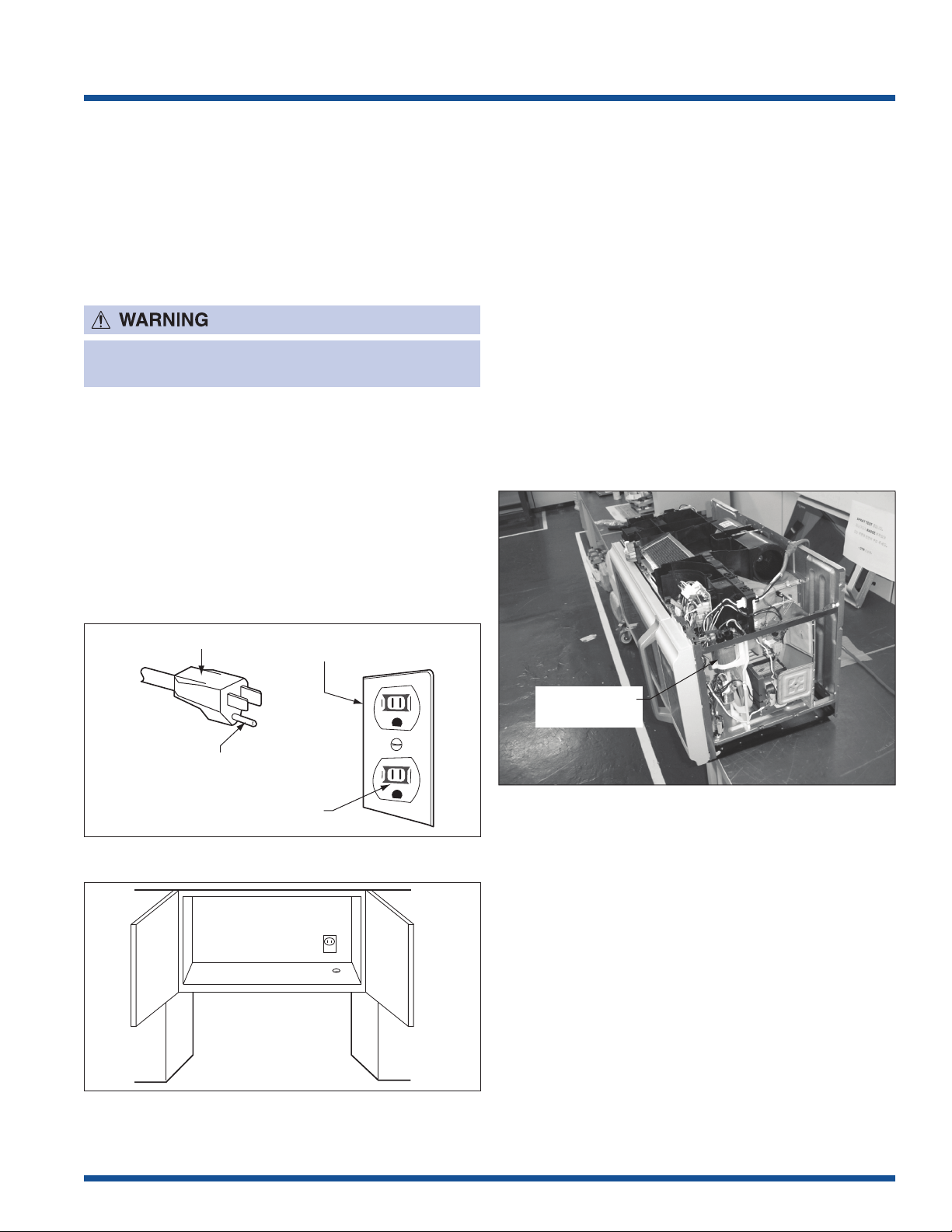
High Voltage
Capacitor
3-Pronged Plug
Grounded
Receptacle Box
Grounding Pin
3-Pronged Receptacle
Grounding Instructions
This oven is equipped with a three prong grounding plug.
It must be plugged into a wall receptacle that is properly
installed and grounded in accordance with the National
Electrical Code, local codes and ordinances. In the event
of an electrical short circuit, grounding reduces the risk of
electric shock by providing an escape wire for the electric
current.
IMPROPER USE OF THE GROUNDING PLUG CAN
RESULT IN A RISK OF ELECTRIC SHOCK.
Electrical Requirements
The oven is equipped with a 3-prong grounding plug.
DO NOT UNDER ANY CIRCUMSTANCES CUT OR
REMOVE THE GROUNDING PIN FROM THE PLUG.
The power supply cord and plug must be connected to a
separate 120 Volt AC, 60 Hz, 15 Amp. or more dedicated
line, using a grounded receptacle. The receptacle should
be located inside the cabinet directly above the
Microwave Oven/Hood system mounting location.
Discharging Capacitor
1. High Voltage Warning!
Do not attempt to measure any of the high voltages,
this includes the filament voltage of the magnetron.
High voltage is present during any cook cycle.
Before touching any components or wiring, always
unplug the oven and discharge the high voltage
capacitor (See Figure 1-3).
2. The high-voltage capacitor remains charged about
60 seconds after disconnection. Short the negative
terminal of the high-voltage capacitor to the oven
chassis. (Use an insulated screwdriver.)
3. High voltage is maintained within specified limits
by close-tolerance, safety-related components
and adjustments. If the high voltage exceeds the
specified limits, check each of the special
components.
Figure 1-1. Electrical Connection
Figure 1-2. Electrical Connection In Cabinet
Figure 1-3. Capacitor Discharging
NOTE: The illustration above gives a generalized
location of the high voltage capacitor. Refer to the
exploded view of the oven and cabinet for exact
location.
1-9

Basic Information
Oven Diagram
Components
1. Microwave oven door with see-through window.
2. Door hinges.
3. Waveguide cover: DO NOT REMOVE.
4. Turntable motor shaft.
5. Microwave oven light. It will light when microwave
oven is operating or door is open.
6. Rack holders.
7. Safety door latches. The microwave oven will not
operate unless the door is securely closed.
8. Handle.
9. Light pad. Touch the light pad once for high, twice for
medium, three times for low and four times to turn off
the light.
10. Fan pad. Touch the fan pad once for high speed,
twice for medium speed, three times for low speed
and four times to turn off the fun.
11. Auto-Touch control panel.
12. Time display: Digital display, 99 minutes, 99 seconds
13. Ventilation openings.
14. Removable turntable. The turntable will rotate
clockwise or counterclockwise. Only remove for
cleaning.
15. Removable turntable support. First, carefully place
the turntable support in the motor shaft in the center
of the microwave oven floor. Then, place the turntable
on the turntable support securely.
16. Rack for 2-level cooking/ reheating.
17. Light cover.
18. Grease filters.
19. Menu label.
20. Rating label (model and serial number).
Figure 1-4. Oven Overview
1-10

Basic Information
Special Instructions for the
Turntable Support and Turntable
Glass Tray
Make sure to remove the tape at the turntable
support before operation. Because the tape is
attached when the product is shipped from the
factory.
Remove this tape before operation
Figure 1-5. Turntable Support Installation
Turntable Support
Oven Bottom Plate Hole
Figure 1-5a.
Figure 1-5b.
Turntable Support
Read carefully before installing the turntable glass tray
and turtable support for proper operation. Improper
installation will cause dragging noise and erratic turntable
glass rotation.
1. Place the turntable support to the turntable motor
shaft (Inside oven bottom plate hole). And make
sure the center of turntable support is inserted to
turntable motor shaft.
2. The turntable glass tray should be set so all three
rollers of the turntable support contact to the flat
surface of the turntable glass tray.
Back
View
Figure 1-5c.
CORRECT WRONG
Flat Surface of Turntable Glass Tray Flat Surface of Turntable Glass Tray
Roller of Turntable Support Out of Flat Surface
Side
View
Flat Surface of Turntable Glass Tray Flat Surface of Turntable Glass Tray
Roller of Turntable Support
1-11
Out of Flat Surface

Basic Information
Notes
1-12

Operation
Operating Sequence Description
The following is a description of component functions
during oven operation.
OFF CONDITION
Closing the door activates the door sensing switch and
secondary interlock switch. (In this condition, the monitor
switch contacts are opened.)
When oven is plugged in, 120 volts A.C. is supplied to the
control unit. (See Figure 2-1).
1. The display will show “ENJOY YOUR OVEN, PRESS
CLEAR AND TOUCH CLOCK”.
To set any program or set the clock, you must first
touch the STOP/CLEAR pad. The display will clear,
and “ : “ appears.
COOKING CONDITION
Program desired cooking time by touching the NUMBER
pads. Program the power level by touching the POWER
LEVEL pad and then a Number pad.
When the START pad is touched, the following operations
occur:
1. The contacts of relays are closed and components
connected to the relays are turned on as follows.
(For details, refer to Figure 2-2)
RELAY CONNECTED COMPONENTS
RY-1 Oven Lamp / Fan Motor / Fan Motor
6. When the door is opened during a cook cycle, monitor switch, door sensing switch, secondary interlock
switch, and primary interlock relay are activated with
the following results. The circuits to the antenna
motor, the cooling fan motor, the turntable motor, and
the high voltage components are de-energized, and
the digital read-out displays the time still remaining in
the cook cycle when the door was opened.
7. The monitor switch is electrically monitoring the
operation of the secondary interlock switch and door
sensing switch is mechanically associated with the
door so that it will function in the following sequence.
(1) When the door opens from a closed position, the
primary interlock relay, door sensing switch and
secondary interlock switch open their contacts,
and then the monitor switch contacts close.
(2) When the door is closed from the open position,
the monitor switch contacts open first. Then the
contacts of the secondary interlock switch and
door sensing switch close, and contacts of the
relay (RY1) open.
If the secondary interlock switch and primary interlock
relay (RY2) fail with the contacts closed when the door is
opened, the closing of the monitor switch contacts will
form a short circuit through the monitor fuse, secondary
interlock switch, relay (RY1) and primary interlock relay
(RY2), causing the monitor fuse to blow.
RY-2 Power Transformer
RY-7 Turntable Motor
2. 120 volts AC is supplied to the primary winding of
the power transformer and is converted to about
3.3 volts AC output on the filament winding, and
approximately 2000 volts AC on the high voltage
winding.
3. The filament winding voltage heats the magnetron
filament and the H.V. winding voltage is sent to a
voltage doubler circuit.
4. The microwave energy produced by the magnetron
is channeled through the waveguide into the cavity
feedbox, and then into the cavity where the food
is placed to be cooked.
5. Upon completion of the cooking time, the power
transformer, oven lamp, etc. are turned off, and the
generation of microwave energy is stopped. The
oven will revert to the OFF condition.
2-1
Operation
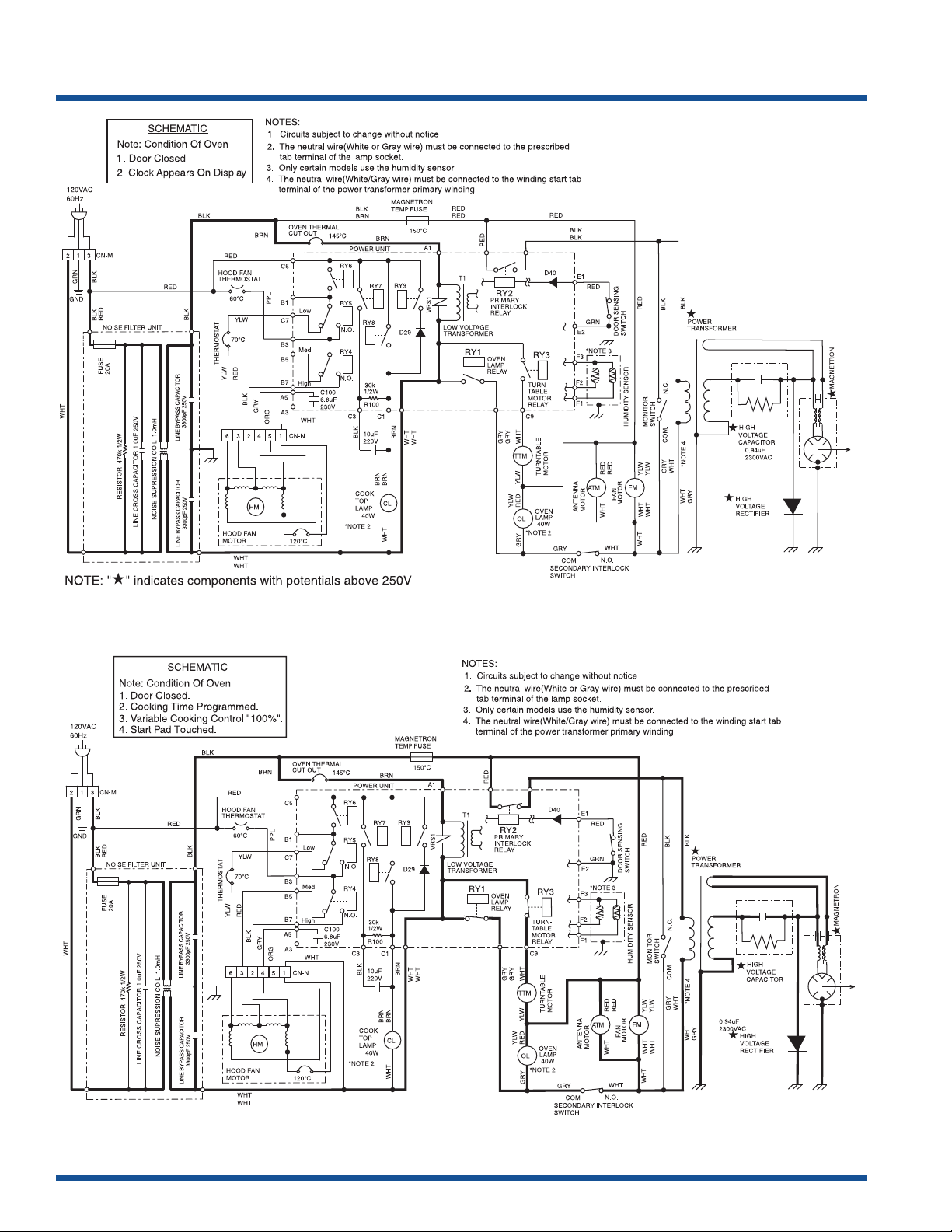
Figure 2-1. Microwave Oven Off Condition
Figure 2-2. Oven Schematic-Microwave Oven Cooking Condition
2-2

Operation
Variable Cooking
When Variable Cooking Power is programmed, the 120
volts A.C. is supplied to the power transformer intermittently through the contacts of relay (RY-2) which is
operated by the control unit within a 32 second time
base. Microwave power operation is as follows:
Vari-Mode ON TIME OFF TIME
Power 10 (High) (100% Power) 32 sec. 0 sec.
Power 9 (P-90) (Approx. 90%) 30 sec. 2 sec.
Power 8 (P-80) (Approx. 80%) 26 sec. 6 sec.
Power 7 (P-70) (Approx. 70%) 24 sec. 8 sec.
Power 6 (P-60) (Approx. 60%) 22 sec. 10 sec.
Power 5 (P-50) (Approx. 50%) 18 sec. 14 sec.
Power 4 (P-40) (Approx. 40%) 16 sec. 16 sec.
Power 3 (P-30) (Approx. 30%) 12 sec. 20 sec.
Power 2 (P-20) (Approx. 20%) 8 sec. 24 sec.
Power 1 (P-10) (Approx. 10%) 6 sec. 26 sec.
Power 0 (P-0) (0% power) 0 sec. 32 sec.
The ON/OFF time ratio does not correspond with the
percentage of microwave power, because approx. 2
seconds are needed for heating of the magnetron
filament.
Ventilation Methods
1. VERTICAL VENTING
For this venting method, hot air rising from the conventional range below is drawn in by the hood fan motor
through the grease filters at the right and left sides of the
base cover, up through the right and left sides of the oven
cavity, then discharged vertically at rear center top of the
oven, into the customer’s vent system.
2. HORIZONTAL VENTING
The air handling is the same as VERTICAL VENTING
except that the final air discharge is directed horizontally
out from the top rear of the oven into the customer’s vent
system.
Power Output Reduction
If the oven is set for over 40 minutes at 80%, 90% or
100% power level, after the first 40 minutes the power
level will automatically adjust itself to 70% power to avoid
overcooking.
Cook Top Lamp
The brightness of the cook top lamp is controlled by the
relays RY7, RY8 and RY9 as shown in the following table.
3. RE-CIRCULATION (INSIDE VENTING)
The air handling is the same as VERTICAL VENTING
except that the final air discharge is directed horizontally
through the upper front of the oven into the kitchen.
2-3

Operation
Sensor Cooking Condition
Using the SENSOR COOK function, the foods are
cooked without figuring time, power level or quantity.
When the oven senses enough steam from the food, it
relays the information to its microprocessor which will
calculate the remaining cooking time and power level
needed for best results.
When food is cooked, water vapor is developed. The
sensor “senses” the vapor and its resistance increases
gradually. When resistance reaches the value set
according to the menu, supplementary cooking is started.
The time of supplementary cooking is determined by
experiment with each food category and inputted into the
LSI.
An example of how the sensor works:
(BAKED POTATOES)
1. Potatoes at room temperature. Vapor is emitted
very slowly.
Cooking Sequence
1. Operate the oven in sensor cooking mode by
referring to the operation manual.
The oven should not be operated on Sensor Cooking
immediately after plugging in the unit. Wait two minutes
before cooking on Sensor Cooking.
2. The coil of shut-off relays (RY1 and RY3) are energized, the oven lamp, turntable motor and cooling fan
motor are turned on, but the power transformer is not
turned on.
3. After about 32 seconds, the relay (RY2) is energized.
The power transformer is turned on, microwave
energy is produced and first stage is started. The 32
seconds is the cooling time required to remove any
vapor from the oven cavity and sensor.
During this first stage, do not open the door or touch
Clear Off pad.
2. Heat Potatoes. Moisture and humidity is emitted
rapidly. You can smell the aroma as it cooks.
MICROWAVE
3. Sensor detects moisture and humidity and
calculates cooking time and variable power.
4. When the sensor detects the vapor emitted from
the food, the display switches over to the remaining
cooking time and the timer counts down to zero.
At this time, the door may be opened to stir food, turn
it or season, etc.
5. When the timer reaches zero, an audible signal
sounds. The shut-off relay (RY1 and RY3) and relay
(RY2) are generalized and the power transformer,
oven lamp, etc. are turned off.
6. Opening the door or touching the STOP CLEAR pad,
the time of day will reappear on the display and the
oven will revert to an OFF condition.
2-4

Operation
Component Descriptions
DOOR OPEN MECHANISM
The door is opened by pulling the door handle down and
forward, referring to Figure 2-6. When the door handle is
pulled down, the latch heads are moved upward. When
the door handle is pulled forward, the latch heads are
released from the latch hooks right and left. Now, the
door will open.
Figure 2-6.
MONITOR SWITCH
The monitor switch is activated (the contacts opened)
by the latch head on the door while the door is closed.
The switch is intended to render the oven inoperative, by
means of blowing the monitor fuse, when the contacts of
the primary interlock relay (RY2) and secondary interlock
switch fail to open when the door is opened.
Functions:
1. When the door is opened, the monitor switch contact
close (to the ON condition) due to their being
normally closed. At this time, the primary interlock
relay (RY2), and secondary interlock switch are in
the OFF condition (contacts open) due to their being
normally open contact switches. The contacts of
relay (RY1) are in the ON condition (contacts close).
2. As the door goes to a closed position, the monitor
switch contacts are first opened and then the door
sensing switch and the secondary interlock switch
contacts close. (On opening the door, each of these
switches operate inversely.)
3. If the door is opened, and the primary interlock relay
(RY2) and secondary interlock switch contacts fail
to open, the monitor fuse blows simultaneously with
closing of the monitor switch contacts.
DOOR SENSING SWITCH, SECONDARY INTERLOCK
SWITCH
The secondary interlock switch is mounted in the lower
position of the latch hook. The door sensing switch in
the primary interlock system is mounted in the upper
position of the latch hook. The switches are activated by
the latch heads on the door. When the door is opened,
the switches interrupt the circuit to all components. A
cook cycle cannot take place until the door is firmly
closed, thereby activating both interlock switches. The
primary interlock system consists of the door sensing
switch and primary interlock relay located on the control
circuit board.
Before replacing a blown monitor fuse test the
door sensing switch, primary interlock relay (RY2),
relay (RY1), secondary interlock switch and monitor
switch for proper operation.
Monitor fuse and switch are replaced as an assembly.
THERMAL CUT-OUT (CAVITY)
This thermal cut-out is located on the top of the oven
cavity. It is designed to prevent damage to the oven unit
if the food in the oven catches fire due to overheating
produced by improper setting of cooking time or failure of
control unit. Under normal operation, the thermal cut-out
remains closed. However, the thermal cut-out will open at
293°F (145°C) causing the oven to shut down.
2-5
 Loading...