

Electrolux EI30MH55GBA, EI30MH55GWA, EI30MH55GZA, EI30MH55GSA, EI30MH55GBB Technical & Service Manual
...
Publication #5995524377 September 2008 P/N 316439261
Models
EI30MH55GBA EI30MH55GSA EI30MH55GWA EI30MH55GZA
EI30MH55GBB EI30MH55GSB EI30MH55GWB EI30MH55GZB


1-1
Section 1
Basic Information
Basic Information

This Manual has been prepared to provide Electrolux Service Personnel with Operation and Service
Information for following Electrolux Microwave Ovens:
EI30MH55GBA, EI30MH55GSA, EI30MH55GWA, EI30MH55GBB, EI30MH55GSB & EI30MH55GWB
Table of Contents
Basic Information
1-2
Section 1 Basic Information .................................. 1-1
Table of Contents .................................................... 1-2
Safe Servicing Practices ........................................ 1-2
Warnings and Safety Information .......................... 1-3
Precautions To Be Observed Before And
During Servicing To Avoid Possible Exposure
To Excessive Microwave Energy............................ 1-5
Before Servicing ...................................................... 1-5
Danger Caution High Voltage ................................ 1-5
Before Servicing ...................................................... 1-6
Servicing the Inverter Unit...................................... 1-7
Microwave Measurement Procedure .................... 1-8
Product Specification.............................................. 1-9
Grounding Instructions .......................................... 1-9
Oven Diagram .......................................................... 1-10
Section 2 Operation
................................................ 2-1
Operating Sequence Description .......................... 2-2
Hot Air Exhaust Ventilation Methods .................... 2-4
Oven Schematic-Off Condition .............................. 2-5
Oven Schematic-Cooking Condition .................... 2-5
Component Descriptions........................................ 2-6
Touch Control Panel Operation.............................. 2-7
Description of LSI.................................................... 2-8
Humidity Sensor Circuit.......................................... 2-11
Section 3 Troub
leshooting and Testing ................ 3-1
Troubleshooting Guide .......................................... 3-2
Troubleshooting Guide Chart ................................ 3-3
Test Procedures ...................................................... 3-4
Section 4 Component
Teardown .......................... 4-1
Servicing .................................................................. 4-2
Precautions for Using Lead-Free Solder .............. 4-3
Warnings .................................................................. 4-4
Hood Louver Removal ............................................ 4-6
Outer Case Removal .............................................. 4-6
Hood Fan Motor Removal ...................................... 4-6
Magnetron Removal ................................................ 4-7
Hood Fan Thermal Cut-out Removal...................... 4-7
Oven Thermal Cut-out Removal ............................ 4-7
Inverter Unit and Fan Motor Replacement............ 4-8
Method for Removing Fan Blade .......................... 4-9
Method for Installing Fan Blade ............................ 4-9
Stirrer Motors Replacement .................................. 4-10
Stirrer Fan Assembly Installation .......................... 4-10
Hood Lamp Sockets Removal................................ 4-10
Oven Lamp and Lamp Socket Removal................ 4-11
Positive Lock ® Connector (No-Case Type).......... 4-11
Control Panel Assembly, Control Unit
and Key Unit Removal ............................................ 4-11
Humidity Sensor Removal...................................... 4-12
Noise Filter Removal .............................................. 4-12
Table Tray Assembly Removal................................ 4-12
Stop Switch, Primary Interlock
Switch, Secondary Interlock Switch
and Monitor Switch ................................................ 4-13
Stop Switch, Primary Interlock
Switch, Secondary Interlock Switch
and Monitor Switch Adjustment ............................ 4-14
Door Replacement .................................................. 4-15
Section 5
Wire Diagrams ........................................ 5-1
Pictorial Diagram .................................................... 5-2
Power Unit Circuit.................................................... 5-3
LSI Unit Circuit ........................................................ 5-4
Printed Wiring Board .............................................. 5-5
Component Descriptions........................................ 2-6
Touch Control Panel Operation.............................. 2-7
Description of LSI.................................................... 2-8
Humidity Sensor Circuit.......................................... 2-11
Section 6 Parts List ................................................ 6-1
Parts List .................................................................. 6-2
Oven Parts Exploded View .................................... 6-4
Cabinet Parts Exploded View ................................ 6-5
Door Parts Exploded View ...................................... 6-6
Packing and Accessories ...................................... 6-7

Basic Information
1-3
Safe Servicing Practices
Avoid personal injury and/or property damage by observing important Safe Servicing Practices.
Following are some limited examples of safe practices:
1. DO NOT attempt a product repair if you have any doubts as to your ability to complete the repair in a safe
and satisfactory manner.
2. Always Use The Correct Replacement Parts as indicated in the parts documentation. Substitutions may
defeat compliance with Safety Standards Set For Home Appliances. Do not exceed maximum
recommended wattage on light bulb replacements. Doing so could blow fuses and/or damage
transformers.
3. Before servicing or moving an appliance:
• Remove power cord from the electrical outlet, trip circuit breaker to the OFF position, or remove fuse.
4. Never interfere with the proper operation of any safety device.
5. Use ONLY REPLACEMENT PARTS CATALOGED FOR THIS APPLIANCE. Substitutions may defeat
compliance with Safety Standards Set For Home Appliances.
6. GROUNDING: The standard color coding for safety ground wires is GREEN, or GREEN with YELLOW
STRIPES. Ground leads are not to be used as current carrying conductors. It is EXTREMELY important
that the service technician reestablish all safety grounds prior to completion of service. Failure to do so will
create a hazard.
7. Prior to returning the product to service, ensure that:
• All electrical connections are correct and secure.
• All electrical leads are properly dressed and secured away from sharp edges, high-temperature
components, and moving parts.
• All non-insulated electrical terminals, connectors, heaters, etc. are adequately spaced away from all metal
parts and panels.
• All safety grounds (both internal and external) are correctly and securely connected.
• All panels are properly and securely reassembled.
© 2008 Electrolux Home Products, Inc.

Basic Information
1-4
THIS SERVICE MANUAL IS INTENDED FOR USE BY PERSONS HAVING ELECTRICAL AND
MECHANICAL TRAINING AND A LEVEL OF KNOWLEDGE OF THESE SUBJECTS GENERALLY
CONSIDERED ACCEPTABLE IN THE APPLIANCE REPAIR TRADE. ELECTROLUX HOME PRODUCTS
CANNOT BE RESPONSIBLE, NOR ASSUME ANY LIABILITY, FOR INJURY OR DAMAGE OF ANY
KIND ARISING FROM THE USE OF THIS MANUAL.
NEVER OPERATE THE OVEN UNTIL THE FOLLOWING POINTS ARE ENSURED.
(A) THE DOOR IS TIGHTLY CLOSED.
(B) THE DOOR BRACKETS AND HINGES ARE NOT DEFECTIVE.
(C) THE DOOR PACKING IS NOT DAMAGED.
(D) THE DOOR IS NOT DEFORMED OR WARPED.
(E) THERE IS NO OTHER VISIBLE DAMAGE WITH THE OVEN.
SERVICING AND REPAIR WORK MUST BE CARRIED OUT ONLY BY TRAINED SERVICE PERSONNEL.
CERTAIN INITIAL PARTS ARE INTENTIONALLY NOT GROUNDED AND PRESENT A RISK OF ELECTRICAL SHOCK ONLY DURING SERVICING. SERVICE PERSONNEL - DO NOT CONTACT THE FOLLOWING
PARTS WHILE THE APPLIANCE IS ENERGIZED;
INVERTER UNIT, HIGH VOLTAGE POWER TRANSFORMER, HIGH VOLTAGE RECTIFIER, HEAT SINK,
MAGNETRON, HIGH VOLTAGE HARNESS ETC.;
IF PROVIDED, VENT HOOD, FAN ASSEMBLY, COOLING FAN MOTOR.
ALL THE PARTS MARKED “*” ON PARTS LIST ARE USED AT VOLTAGES MORE THAN 250V.
REMOVAL OF THE OUTER WRAPPER GIVES ACCESS TO VOLTAGE ABOVE 250V.
ALL THE PARTS MARKED “Ä” ON PARTS LIST MAY CAUSE UNDUE MICROWAVE EXPOSURE, BY
THEMSELVES, OR WHEN THEY ARE DAMAGED, LOOSENED OR REMOVED.
WARNING
WARNING
WARNING

Basic Information
1-5
Precautions To Be Observed Before And During Servicing To
Avoid Possible Exposure To Excessive Microwave Energy
(a) Do not operate or allow the oven to be operated with the door open.
(b) Make the following safety checks on all ovens to be serviced before activating the magnetron or other
microwave source, and make repairs as necessary: (1) interlock operation, (2) proper door closing, (3) seal
and sealing surfaces (arcing, wear, and other damage), (4) damage to or loosening of hinges and latches,
(5) evidence of dropping or abuse.
(c) Before turning on microwave power for any service test or inspection within the microwave generating
compartments, check the magnetron, wave guide or transmission line, and cavity for proper alignment,
integrity, and connections.
(d) Any defective or misadjusted components in the interlock, monitor, door seal, and microwave generation
and transmission systems shall be repaired, replaced, or adjusted by procedures described in this manual
before the oven is released to the owner.
(e) A microwave leakage check to verify compliance with the Federal Performance Standard should be per
formed on each oven prior to release to the owner.
Before Servicing
Before servicing an operative unit, perform a microwave emission check as per the Microwave Measurement
Procedure outlined in this service manual.
If microwave emissions level is in excess of the specified limit, contact Electrolux HOME PRODUCTS, INC.
immediately.
If the unit operates with the door open, service person should 1 ) tell the user not to operate the oven
and 2) contact Electrolux HOME PRODUCTS, INC. and Food and Drug Administration's Center for
Devices and Radiological Health immediately.
Service personnel should inform Electrolux HOME PRODUCTS, INC. of any certified unit found with
emissions in excess of 4mW/cm2. The owner of the unit should be instructed not to use the unit until the
oven has been brought into compliance.
Danger Caution HIGH VOLTAGE
Do not energize a microwave oven with the outer case cabinet removed, because a microwave oven
generates High Voltage in the circuit.
If you intend to operate the oven employing the high frequency switching power converter circuit, you should
take special precautions to avoid an electrical shock hazard.
The high voltage transformer and high voltage diode have energized high voltage potential approx. 8 KV.
The aluminum heat sink is connected to the switching power transistor collector pole, and has an energized
high voltage potential of approx. 650V peak.
DO NOT ACCESS THE HIGH VOLTAGE TRANSFORMER , HIGH VOLTAGE DIODE AND HEAT SINK WHEN
THE POWER SUPPLY IS CONNECTED TO AN ELECTRICAL OUTLET.
Basic Information
1-6
Before Servicing
1. Disconnect the power supply cord , and then
remove outer case.
2. Open the door and block it open.
Whenever troubleshooting is performed the power
supply must be disconnected. It may, in some cases,
be necessary to connect the power supply after the
outer case has been removed, in this event:
1. Disconnect the power supply cord, and then
remove outer case.
2. Open the door and block it open.
3. Disconnect the leads to the primary of the
inverter unit.
4. Ensure that these leads remain isolated from
other components and oven chassis by using
insulation tape.
5. After that procedure, reconnect the power supply
cord.
When the testing is completed,
1. Disconnect the power supply cord, and then
remove outer case.
2. Open the door and block it open.
3. Reconnect the leads to the primary of the
inverter unit.
4. Reinstall the outer case (cabinet).
5. Reconnect the power supply cord after the outer
case is installed.
6. Run the oven and check all functions.
After repairing
1. Reconnect all leads removed from components
during testing.
2. Reinstall the outer case (cabinet).
3. Reconnect the power supply cord after the outer
case is installed.
4. Run the oven and check all functions.
Microwave ovens should not be run empty. To
test for the presence of microwave energy within
a cavity, place a cup of cold water on the oven
turntable, close the door and set the power to
HIGH and set the microwave timer for two (2)
minutes. When the two minutes has elapsed
(timer at zero) carefully check that the water is
now hot. If the water remains cold carry out
Before Servicing procedure and re-examine
the connections to the component being tested.
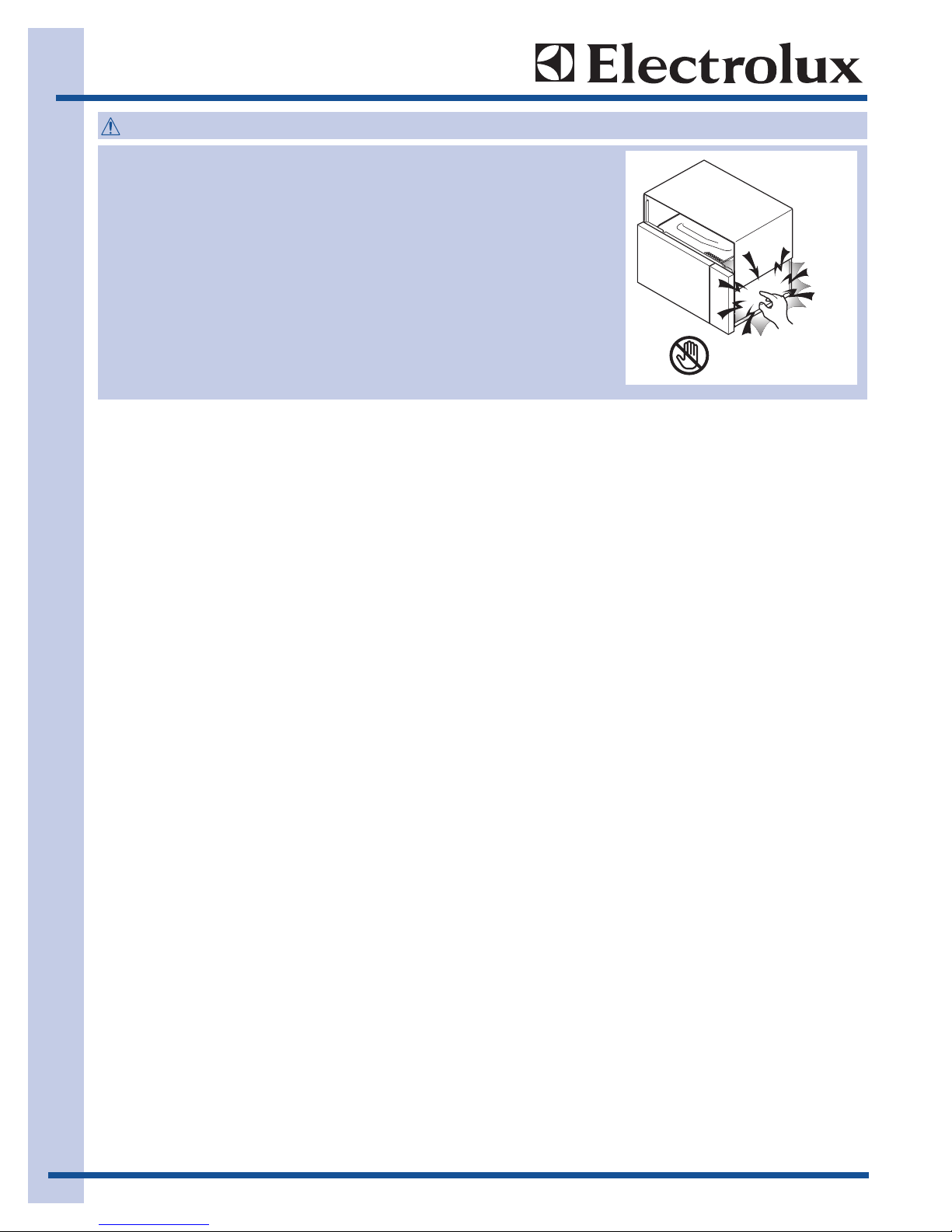
MICROWAVE OVENS CONTAIN CIRCUITRY CAPABLE OF
PRODUCING VERY HIGH VOLTAGE AND CURRENT, CONTACT WITH
FOLLOWING PARTS MAY RESULT IN A SEVERE, POSSIBLY FATAL,
ELECTRICAL SHOCK.
(EXAMPLE)
INVERTER UNIT THAT INCLUDES HIGH VOLTAGE POWER
TRANSFORMER, HIGH VOLTAGE RECTIFIER, HEAT SINK ETC.,
AND MAGNETRON, HIGH VOLTAGE HARNESS ETC..
READ THE SERVICE MANUAL CAREFULLY AND FOLLOW ALL
INSTRUCTIONS.
WARNING
Don't Touch !
Danger High Voltage

Basic Information
1-7
Servicing the Inverter Unit
Microwave Measurement Procedure
A. Requirements:
1) Microwave leakage limit (Power density limit): The power density of microwave radiation emitted by a
microwave oven should not exceed 1 mW/cm2 at any point 5cm or more from the external surface of
the oven, measured prior to acquisition by a purchaser, and thereafter (through the useful life of the
oven), 5 mW/cm2 at any point 5cm or more from the external surface of the oven.
2) Safety interlock switches: Primary interlock switch shall prevent microwave radiation emission in
excess of the requirement as above mentioned, secondary interlock switch shall prevent microwave
radiation emission in excess of 5 mW/cm2 at any point 5cm or more from the external surface of the
oven.
B. Preparation for testing:
Before beginning the actual measurement of leakage, proceed as follows:
1) Make sure that the actual instrument is operating normally as specified in its instruction booklet.
Important:
Survey instruments that comply with the requirement for instrumentation as prescribed by the
performance standard for microwave ovens, 21 CFR 1030.10(c)(3)(i), must be used for testing.
2) Place the oven tray in the oven cavity.
3) Place the load of 275±15 ml (9.8 oz) of tap water initially at 20o±5C (68oF) in the center of the oven
cavity. The water container shall be a low form of 600 ml (20 oz) beaker with an inside diameter of
approx. 8.5 cm (3-1/2 in.) and made of an electrically nonconductive material such as glass or plastic.
The placing of this standard load in the oven is important not only to protect the oven, but also to
insure that any leakage is measured accurately.
4) Set the cooking control on Full Power Cooking Mode
5) Close the door and select a cook cycle of several minutes. If the water begins to boil before the
survey is completed, replace it with 275 ml of cool water.
C. Leakage test:
Closed-door leakage test (microwave measurement)
1) Grasp the probe of the survey instrument and hold it perpendicular to the gap between the door and
the body of the oven.
2) Move the probe slowly, not faster than 1 in./sec. (2.5 cm/sec.) along the gap, watching for the
maximum indication on the meter.
3) Check for leakage at the door screen, sheet metal seams and other accessible positions where the
continuity of the metal has been breached (eg., around the switches, indicator, and vents).
While testing for leakage around the door pull the door away from the front of the oven as far as is
permitted by the closed latch assembly.
4) Measure carefully at the point of highest leakage and make sure that the highest leakage is no greater
than 4mW/cm2, and that the primary interlock switch and secondary interlock switch do turn the oven
OFF before any door movement.
NOTE: After servicing, record data on service invoice and microwave leakage report.
THIS INVERTER UNIT CONTAINS CIRCUITRY CAPABLE OF PRODUCING HIGH VOLTAGE AND HIGH
CURRENT. CONTACT WITH ANY PART OF THE HIGH VOLTAGE WILL RESULT IN ELECTROCUTION.
DO NOT ACCESS ANY PARTS OF INVERTER UNIT WITH POWER SUPPLY CONNECTED.
DO NOT OPERATE INVERTER UNIT ITSELF.
IT IS DANGEROUS BECAUSE THIS UNIT CONTAINS HIGH VOLTAGE COMPONENTS.
WARNING
Basic Information
1-8
Product Specification
Item Description
Power Requirements 120 Volts / 12 Amperes
60 Hertz
Single phase, 3 wire grounded
Power Output 1200 watts (IEC TEST PROCEDURE)
Operating frequency of 2450MHz
Case Dimensions Width 29-15/16"
Height 17"
Depth 15- 9/16"
Cooking Cavity Dimensions Width 22-9/16"
Height 10-9/16"
2.1 Cubic Feet Depth 15"
Hood lamp 2 bulbs, 20W x 2, Incandescent light bulbs
Hood fan Approx. High - 300 C.F.M. / Low - 270 C.F.M.
Control Complement Touch Control System
Clock ( 1:00 - 12:59 )
Timer (0 - 99 min. 99 seconds)
Microwave Power for Variable Cooking
Repetition Rate;
P-HI Full power throughout the cooking time
P-90 approx. 90% of Full Power
P-80 approx. 80% of Full Power
P-70 approx. 70% of Full Power
P-60 approx. 60% of Full Power
P-50 approx. 50% of Full Power
P-40 approx. 40% of Full Power
P-30 approx. 30% of Full Power
P-20 approx. 20% of Full Power
P-10 approx. 10% of Full Power
P-0 No power throughout the cooking time
Quick Breakfast, Express Lunch, Dinner Recipes, Popcorn, Reheat,
Soften, Melt, Warm, Keep Warm, Cook, Defrost, Power Level,
Number selection pads, Power Level pad, Timer/Clock pad,
Stop/Clear pad, User Pref, Start Add a Minute pad, Light, Fan
Oven Cavity Light 20W x 1 Incandescent light bulb
Safety Standard UL Listed FCC Authorized
DHHS Rules, CFR, Title 21, Chapter 1, Subchapter J
Canadian Standards Association
Health CANADA, Industry Canada
Weight Approx. 44 lbs.
Basic Information
1-9
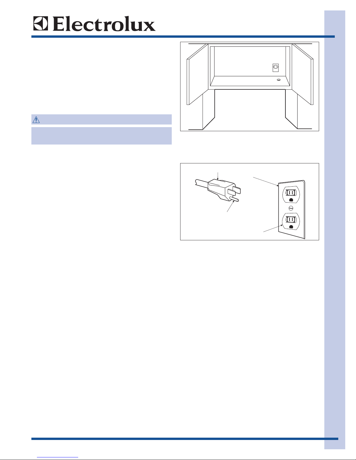
Grounding Instructions
This oven is equipped with a three prong grounding
plug. It must be plugged into a wall receptacle that is
properly installed and grounded in accordance with
the National Electrical Code and local codes and
ordinances.
In the event of an electrical short circuit, grounding
reduces the risk of electric shock by providing an
escape wire for the electric current.
Electrical Requirements
The oven is equipped with a 3-prong grounding plug.
DO NOT UNDER ANY CIRCUMSTANCES CUT OR
REMOVE THE GROUNDING PIN FROM THE PLUG.
The power supply cord and plug must be connected
to a separate 120 Volt AC, 60 Hz, 15 Amp or more
dedicated line, using a grounded receptacle.
The receptacle should be located inside the cabinet
directly above the Microwave Oven/Hood system
mounting location.
IMPROPER USE OF THE GROUNDING PLUG
CAN RESULT IN A RISK OF ELECTRIC SHOCK.
WARNING
3-Pronged Plug
Grounding Pin
3-Pronged Receptacle
Grounded
Receptacle Box
Basic Information
1-10
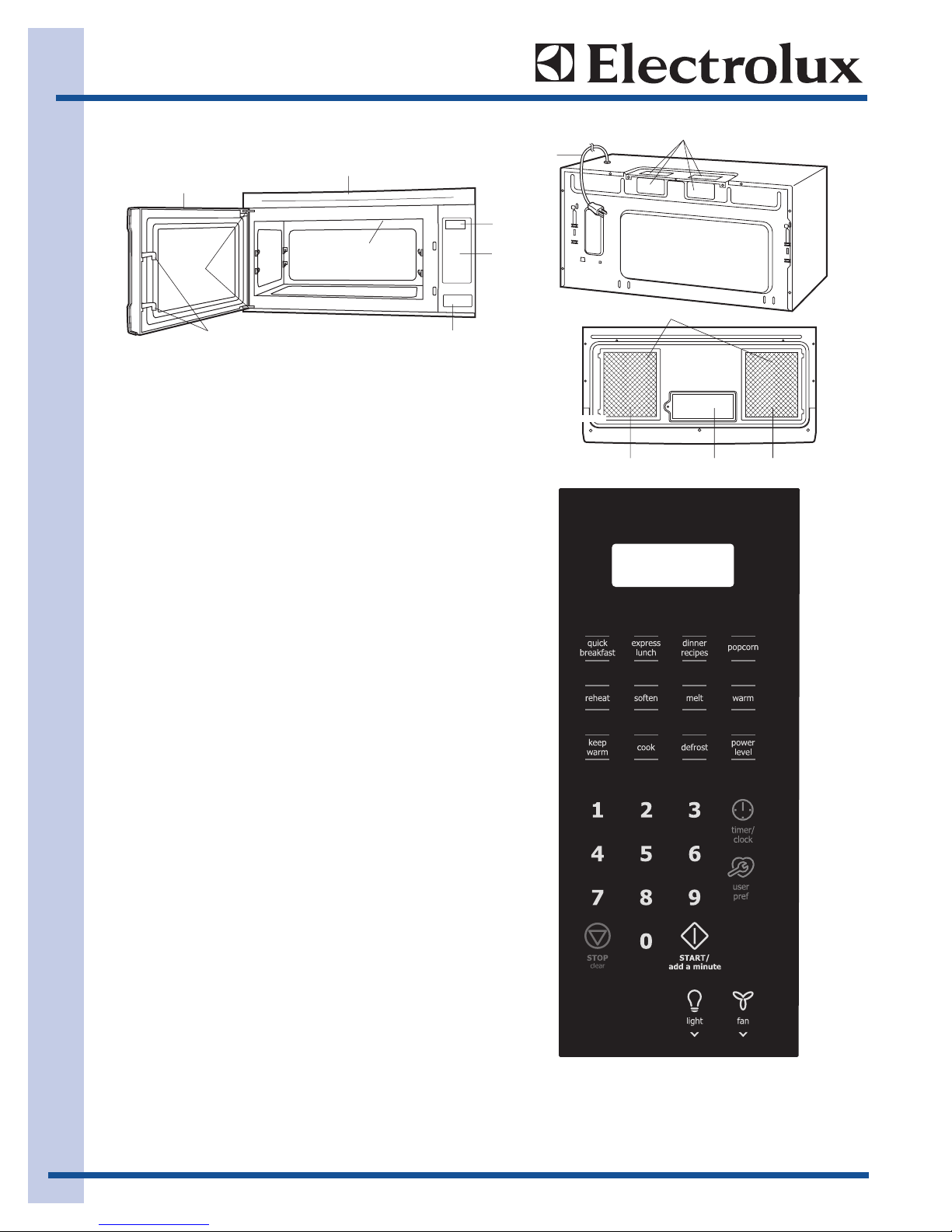
NOTE: Some one-touch cooking features such as
"ADD A MINUTE" are disabled after three minutes
when the oven is not in use.These features are
automatically enabled when the door is opened and
closed or the STOP/CLEAR pad is pressed.
1. Oven door with see-through window.
2. Door hinges.
3. Oven lamp.
It will light when oven is operating or door is
open.
4. Door latches.
The oven will not operate unless the door is
securely closed.
5. One touch door open button
6. Auto-Touch control panel.
7. Timer display: Digital display, 99 minutes
00 seconds.
8. Ventilation openings.
9. Light Cover.
10. Grease filters.
11. Power supply cord
Oven Diagram
8
1
3
2
4
8
11
7
6
8
5
10
901

2-1
Section 2
Operation
Operation

Operation
2-2
The following is a description of component functions
during oven operation.
OFF CONDITION
Closing the door activates the stop switch, primary
interlock switch and secondary interlock switch. (In
this condition, the monitor switch contacts are
opened.) When oven is plugged in, 120 volts A.C. is
supplied to the control unit. (Figure O-1).
1. The display will show "Enjoy your oven, press
clear and press clock". To set any program or set
the clock, you must first touch the STOP/CLEAR
button. The display will clear, and " : " appears.
COOKING CONDITION
Program desired cooking time touching the NUMBER
pads. When the START button is touched, the
following operations occur:
1. The contacts of relays are closed and
components connected to the relays are turned
on as follows. (For details, refer to Figure O-2)
RELAY CONNECTED COMPONENTS
RY1 Oven lamp / Fan motor / Stirrer motor
RY3, RY4 Hood fan motor
2. 120 volts A.C. is supplied to the inverter unit and
is converted in order to power of the magnetron
by the high frequency switching power circuit.
The frequency is approx. 33-45 KHz.
3. The filament winding voltage of H.V. transformer
heats the magnetron filament and H.V. winding
gives a high voltage approx. 2 KV to activate
a voltage doubler circuit. Then approx. 4KV peak
voltage power is supplied to the magnetron
cathode terminal.
4. The microwave energy produced by the
magnetron is channeled through the waveguide
into the cavity feedbox, and then into the cavity
where the food is placed to be cooked.
5. Upon completion of the cooking time, the inverter
unit, oven lamp, etc. are turned off, and the
generation of microwave energy is stopped. The
oven will revert to the OFF condition.
6. When the door is opened during a cook cycle,
the monitor switch, stop switch, secondary
interlock switch and primary interlock switch are
activated with the following results.The circuits to
the stirrer motor, the cooling fan motor, the
turntable motor, and the inverter unit are
de-energized,and the touch screen displays the
time still remaining in the cook cycle when the
door was opened.
7. The monitor switch is electrically monitoring the
operation of the secondary interlock switch and
primary interlock switch and is mechanically
associated with the door so that it will function in
the following sequence.
(1) When the door opens from a closed
position, the primary interlock switch and
secondary interlock switch open their
contacts, and then the monitor switch
contacts close. And contacts of the relay
(RY1) remain closed.
(2) When the door is closed from the open
position, the monitor switch contacts first
open and the stop switch contacts open, and
then the contacts of the secondary interlock
switch and primary interlock switch close.
And contacts of the relay (RY1) open.
If the secondary interlock switch and primary interlock
switch fail with their contacts closed when the door is
opened, the closing of the monitor switch contacts will
form a short circuit through the monitor fuse, secondary interlock switch, primary interlock switch and relay
(RY1) causing the monitor fuse to blow.
Operating Sequence
Description
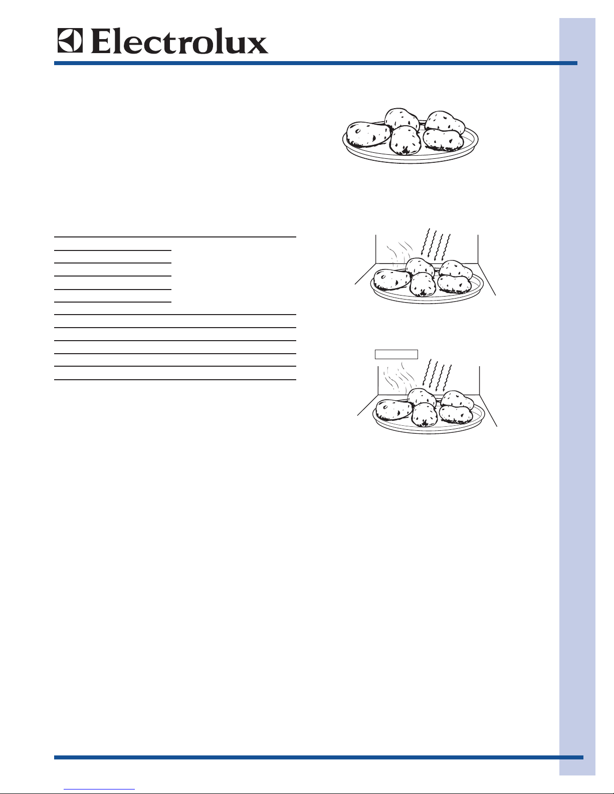
An example of how the sensor works:
(BAKED POTATOES)
1. Potatoes at room temperature. Vapor is emitted
very slowly.
2. Heat Potatoes. Moisture and humidity is emitted
rapidly. You can smell the aroma as it cooks.
3. Sensor detects moisture and humidity and
calculates cooking time and variable power.
Cooking Sequence.
1. Operate the oven in sensor cooking mode by
referring to the operation manual.
NOTE: The oven should not be operated on SENSOR
immediately after plugging in the unit. Wait two
minutes before cooking on SENSOR.
2. The coil of shut-off relay (RY-1) is energized, the
turntable motor, oven lamp and cooling fan motor
are turned on, but the inverter unit is not turned
on.
3. After about 32 seconds, the cook relay (RY-2) is
energized. The power transformer is turned on,
microwave energy is produced and first stage is
started. The 32 seconds is the cooling time
required to remove any vapor from the oven
cavity and sensor.
NOTE: During this first stage, do not open the door or
touch STOP/CLEAR pad.
Operation
2-3
VARIABLE COOKING
When Variable Cooking Power is programmed, the
120 volts A.C. is supplied to the inverter unit which is
operated by the control unit. Microwave power
operation is as follows:
The oven can be set for any of 11 power levels: 0% to
100%(HIGH). The variable cooking power less than
40% is programmed at the ratio of ON time and OFF
time within 32 sec./ cycle time base.
Connection between power setting and ON/OFF time
of inverter unit.
OUTPUT POWER SETTING ON TIME OFF TIME
Power 100%
Power 90%
Power 80%
Power 70% Continue operation
Power 60%
Power 50%
Power 40% 26 sec. 6 sec.
Power 30% 22 sec. 10 sec.
Power 20% 16 sec. 16 sec.
Power 10% 8 sec. 24 sec.
Power 0% 0 sec. 32 sec.
NOTE: The ON/OFF time ratio does not correspond
with the percentage of microwave power, because
approx. 3 seconds are needed for heating of the magnetron filament.
SENSOR COOKING CONDITION
Using the Sensor cooking function the food is cooked
without figuring time, power level or quantity. When
the oven senses enough steam from the food, it
relays the information to its microprocessor which will
calculate the remaining cooking time and power level
needed for best results. When the food is cooked,
water vapor is developed. The sensor
“senses” the vapor and its resistance increases
gradually. When the resistance reaches the value set
according to the menu, supplementary cooking is
started. The time of supplementary cooking is
determined by experiment with each food category
and input into the LSI.
MICROWAVE
AH SENSOR
MICROWAVE
Operation
2-4
4. When the sensor detects the vapor emitted from
the food, the display switches over to the
remaining cooking time and the timer counts
down to zero. At this time, the door may be
opened to stir, turn, or season food.
5. When the timer reaches zero, an audible signal
sounds. The shut-off relay is de-energized and
the inverter unit, oven lamp, etc. are turned off.
6. Opening the door or touching the STOP/CLEAR
pad, the time of day will reappear on the display
and the oven will revert to an OFF condition.
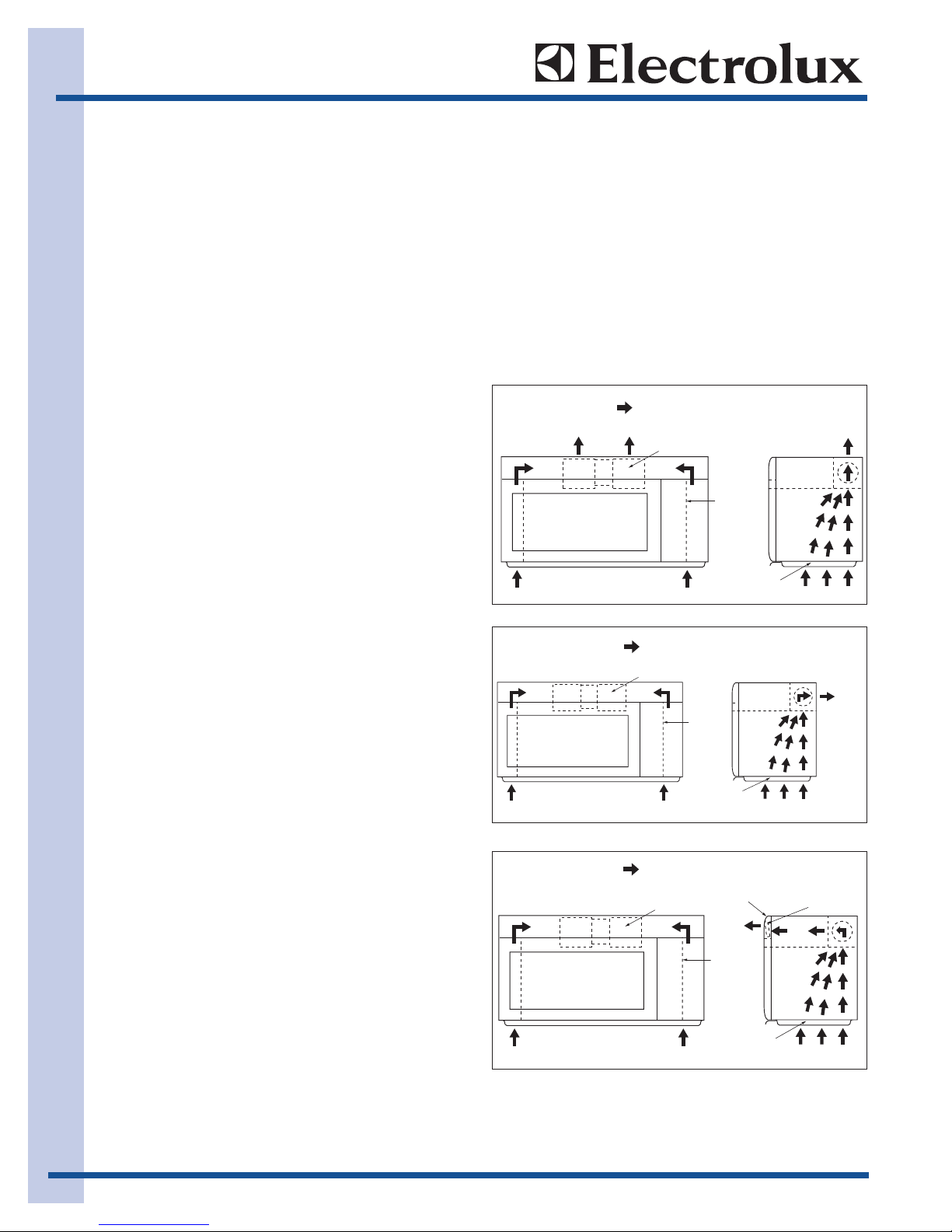
Hot Air Exhaust Ventilation
Methods
1. VERTICAL VENTING
For this venting method, hot air rising from the
conventional range below is drawn in by the hood fan
motor through the grease filters at the right and left
sides of the base cover, up through the right and left
sides of the oven cavity, then discharged vertically at
rear center top of the oven, into the customer's vent
system.
2. HORIZONTAL VENTING
The air handing is the same as VERTICAL VENTING
except that the final air discharge is directed
horizontally out from the top rear of the oven into the
customer's vent system.
3. RE-CIRCULATION (INSIDE VENTING)
The air handing is the same as VERTICAL VENTING
except that the final air discharge is directed
horizontally through the upper front of the oven into
the kitchen. In this case, the accessory charcoal filter
RK-260 must be provided to filter the air before it
leaves the oven.
TO DUCT
: AIR FLOW
HOOD FAN MOTOR
TO DUCT
HOOD
INTAKE
DUCT R
GREASE
FILTER
: AIR FLOW
HOOD FAN MOTOR
: AIR FLOW
HOOD FAN MOTOR
HOOD
INTAKE
DUCT R
GREASE
FILTER
HOOD EXHAUST
LOUVER
HOOD
INTAKE
DUCT R
GREASE
FILTER
TO DUCT
CHARCOAL
FILTER
Operation
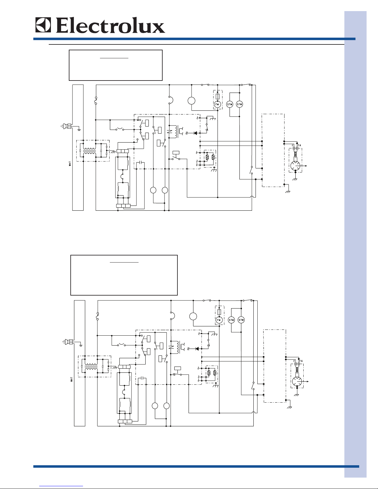
2-5
SCHEMATIC
NOTE: CONDITION OF OVEN
1. DOOR CLOSED
2. CLOCK APPEARS ON DISPLAY
GRO
DER
FUSE
NOISE
DER
L
20A
DER
DE
R
C3
C2
C4
FILTER
YRG
U
L
B
HOOD
MOTOR
RED
RED
HOOD FAN
THERMAL
CUT OUT
U
L
B
U
L
B
RED
Y
BLK
KL
B
WLY
120VAC
60Hz.
K
L
B
H
GRN
GND
N
C1
SECONDARY
INTERLOCK
SWITCH
MOTOR
WHT
RED
NRB
RED
BLK
NR
B
THW
MONITOR
SWITCH
RED
BLK
N.O.COM
DER
KLB
T
HW
A1
COM
FA
F
A3
RED
AC3
N.C.
WHT
M
BLU
INVERTER
UL
B
UNIT
YRG
ULB
NORT
E
NGAM
BRN
RED
ORG
BLK
PRIMARY
SWITCH
FAN
MOTOR
WITH
TEMP.FUSE
GRN
E2
E1
BLK
H1
H3
F3
F2
F1
HUMIDITY
SENSOR
N.O.
STOP
SWITCH
DER
NRB
THW
THW
THW
STIRRER
TH
W
RY1
OVEN
LAMP
COM.
WHT
DER
THW
BLU
COM
INTERLOCK
DE
R
L
NC
CUT OUT
L UNIT
LPProNRB
HL
U
L
B
A
G
R
O
C3
LVT
RY5
OVEN
LAMP
RY6
RELAY
N. O.
A7
A9
GROroWLY
HOOD
YRG
YRG
LAMP
HL
U
ULB
L
B
ULB
OVEN THERM
CONTRO
A5
B1
W
L
RY4
C5
RY3
High
T
H
B3
Low
W
HOOD
CAPACITOR
A3
A1
DER
W
L
Y
DER
NOTES:
1. Circuits / Wire Colors subject to change without notice.
2. Terminal that located to the right side on the lamp socket's back view
must be connected to neutral wire.
3. Only certain models use the absolute humidity sensor
Figure O-1. Oven Schematic-Off Condition
SCHEMATIC
NOTE: CONDITION OF OVEN
1. DOOR CLOSED
2. COOKING TIME PROGRAMMED
3. VARIABLE COOKING CONTROL
"HIGH"
G
DE
RO
R
FUSE
NOISE
D
E
R
L
20A
DE
D
E
R
R
C3
C2
C4
FILTER
YRG
ULB
HOOD
MOTOR
RED
RED
HOOD FAN
THERMAL
CUT OUT
UL
B
ULB
RED
L
Y
BLK
K
LB
WLY
120VAC
60Hz.
K
L
B
H
GRN
GND
N
C1
NOTES:
1. Circuits / Wire Colors subject to change without notice.
2. Terminal that located to the right side on the lamp socket's back view
must be connected to neutral wire.
3. Only certain models use the absolute humidity sensor
A5
B1
W
C5
TH
B3
W
DER
CONTROL UNIT
High
Low
HOOD
CAPACITOR
A3
A1
DE
WLY
R
OVEN
RY4
NC
RY3
Figure O-2. Oven Schematic-Cooking Condition
THERMA L
CUT OUT
RY6
A9
LP
Pr
oNRB
HOOD
LAMP
HL
ULB
SECONDARY
INTERLOCK
SWITCH
MOTOR
WHT
RED
N
RB
RED
BLK
N
R
B
MONITOR
SWITCH
RED
BLK
N.O.COM
DER
K
LB
T
THW
HW
A1
COM
FA
F
A3
RED
AC3
N.C.
WHT
M
BLU
INVERTER
U
L
B
UNIT
YRG
ULB
N
O
RTENGA
M
BRN
RED
ORG
BLK
N.O.
PRIMARY
SWITCH
FAN
MOTOR
WITH
TEMP.FUSE
GRN
E2
E1
BLK
H1
H3
F3
F2
F1
HUMIDITY
SENSOR
STOP
SWITCH
DER
NRB
T
H
THW
THW
STIRRER
W
TH
W
OVEN
LAMP
COM
DER
INTERLOCK
THW
DER
GR
O
C3
LVT
RY5
OVEN
LAMP
RELAY
RY1
COM.
N. O.
A7
GROr
o
WLY
Y
YRG
R
HL
G
WHT
ULB
U
LB
ULB
BLU
Operation
2-6
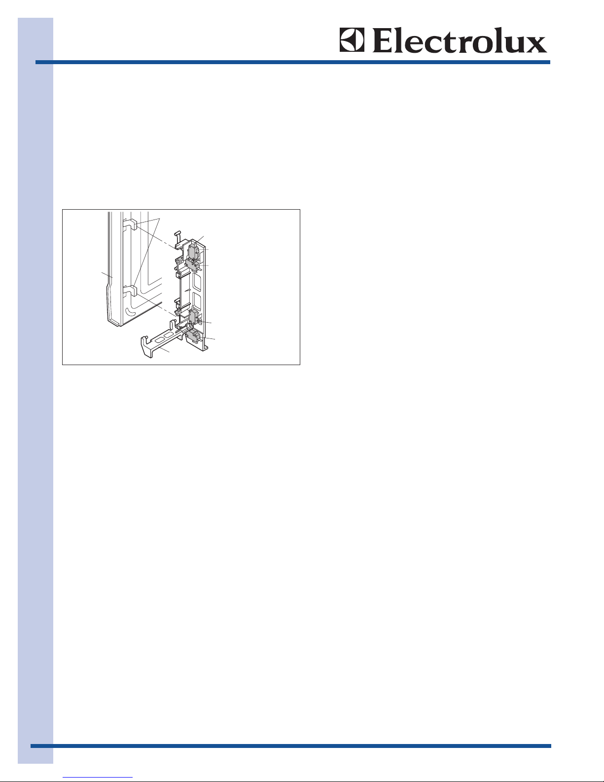
DOOR OPEN MECHANISM
The door is opened by pushing the open button on
the control panel, refer to the Figure D-1.
When the open button is pushed, the open button
pushes up the open lever, and then the open lever
pushes up the latch head. The latch heads are moved
upward and released from latch hook. Now the door
will open.
STOP, PRIMARY INTERLOCK AND SECONDARY
INTERLOCK SWITCHES
The secondary interlock switch is mounted in the
lower position of the latch hook and the stop switch is
mounted in the upper position of the latch hook. The
primary interlock switch is also in the upper position of
the latch hook. They are activated by the latch heads
on the door. When the door is opened, the switches
interrupt the circuit to all components.
A cook cycle cannot take place until the door is firmly
closed thereby activating both interlock switches.
MONITOR SWITCH
The monitor switch is activated (the contacts opened)
by the latch head on the door while the door is
closed. The switch is intended to render the oven
inoperative by means of blowing the monitor fuse
when the contacts of the primary interlock switch and
secondary interlock switch fail to open when the door
is opened.
Functions:
1. When the door is opened, the monitor switch
contact close (to the ON condition) due to their
being normally, closed. At this time the primary
interlock switch and secondary interlock switch
are in the OFF condition (contacts open) due to
their being normally open contact switches. And
the contacts of relay (RY1) are in the ON
condition (contacts close).
2. As the door goes to a closed position, the
monitor switch contacts are first opened and the
stop switch contacts close, and then the primary
interlock switch and the secondary interlock
switch contacts close. (On opening the door,
each of these switches operate inversely.)
3. If the door is opened, and the primary interlock
switch and secondary interlock switch contacts
fail to open, the monitor fuse blows simultaneously with closing of the monitor switch contacts.
CAUTION: Before replacing a blown monitor fuse,
test the stop switch, primary and secondary interlock
switch and monitor switch for proper operation.
NOTE: Monitor fuse and switch are replaced as an
assembly
THERMAL CUT-OUT (HOOD )
This thermal cut-out located on the right base plate. It
is designed to automatically turn on the hood fan
motor whenever the hot air rising from the conventional range below causes the temperature at the thermal
cut-out to rise to 140F (60C) or higher, thus removing
this hot air from around microwave oven. When the
temperature around the thermal cut-out drops to 113F
(45C) or lower, the thermal cut-out shuts off the hood
fan motor.
THERMAL CUT-OUT (OVEN )
This thermal cut-out is located on the top of the oven
cavity. It is designed to prevent damage to the oven
unit if the food in the oven catches fire due to overheating produced by improper setting of cooking time
or failure of control unit. Under normal operation, the
thermal cut-out remains closed. However, the thermal
cut-out will open at 293F (145C) causing the oven to
shut down.
COOLING FAN MOTOR
The cooling fan motor drives a blade which draws
external cool air.This cool air is directed through the
air vanes surrounding the magnetron and cools the
magnetron. This air is channeled through the oven
cavity to remove steam and vapors given off from the
heating foods. It is then exhausted through the
exhausting air vents at the oven cavity.
h
Figure D-1. Door Open Mechanism
Component Descriptions
Latch heads
Latch hook
Stop switch
Door
Open lever
Primary
interlock switch
Monitor switch
Secondary
interlock switc

Operation
2-7
HOOD FAN MOTOR
The hood fan motor is a two-speed, single-phase,
double pole induction type, requiring a hood fan
capacitor. It is located outside the upper rear part of
the oven cavity, is to remove, from around the oven,
hot air rising from the conventional electric or gas
range over which it is installed. This air is then
expelled either vertically or horizontally through the
customer supplied duct system, or discharged back
into the kitchen.
STIRRER MOTOR
The stirrer motors drive the stirrer fans to stir the
microwave radiation from the waveguide.
HOOD LAMP
The hood lamps are mounted at the hood lamp angle.
The hood lamps can be turned off and on by touching
the Light Options pad. And also the brightness can be
varied to high or low by touching the Light Options
pad.
Touch Control Panel Operation
The touch control section consists of the following
units as shown in the touch control panel circuit.
(1) Key Unit
(2) Control Unit (The Control unit consists of LSI Unit
and Power Unit)
The principal functions of these units and the signals
communicated among them are explained below.
Key Unit
The key unit is composed of a matrix, signals
generated in the LSI are sent to the key unit through
P20, P21, P22, P23, P24, P25, P26 and P27.
When a key pad is touched, a signal is completed
through the key unit and passed back to the LSI
through P43, P44, P45 and P46 to perform the
function that was requested.
Control Unit
Control unit consists of LSI, power source circuit, synchronizing signal circuit, reset circuit, buzzer circuit,
relay circuit indicator circuit, back light circuit and
humidity sensor circuit.
1) LSI
This LSI controls the key strobe signal, relay
driving signal for oven function and indicator
signal.
2) Power Source Circuit
This circuit generates voltages necessary for the
control unit from the AC line voltage.
In addition, the synchronizing signal is available
in order to compose a basic standard time in the
clock circuit.
Symbol Voltage Application
VC -5.0V LSI(IC1)
3) Synchronizing Signal Circuit
The power source synchronizing signal is avail
able in order to compose a basic standard time
in the clock circuit. It incorporates a very small
error because it works on commercial frequency.
4) Reset Circuit
A circuit to generate a signals which resetting the
LSI to the initial state when power is applied.
5) Buzzer Circuit
The buzzer is responds to signals from the LSI to
emit audible sounds (key touch sound and
completion sound).
6) Stop Switch
A switch to inform the LSI if the door is open or
closed.
7) Relay Circuit
To drive the inverter unit, fan motor, stirrer motor,
hood motor, and light the oven lamp and hood
lamp.
8) Indicator Circuit
This circuit consists of 25 segments and 4
common electrodes using a Light Crystal Display.
9) Back Light Circuit
A circuit to drive the back light (Light emitting
diodes LD1-LD5).
10) Humidity Sensor Circuit
This circuit detects moisture of the cooking food
to allow its automatic cooking.
11) Inverter Unit Control Circuit
This is the circuit to control inverter unit.
Operation
2-8
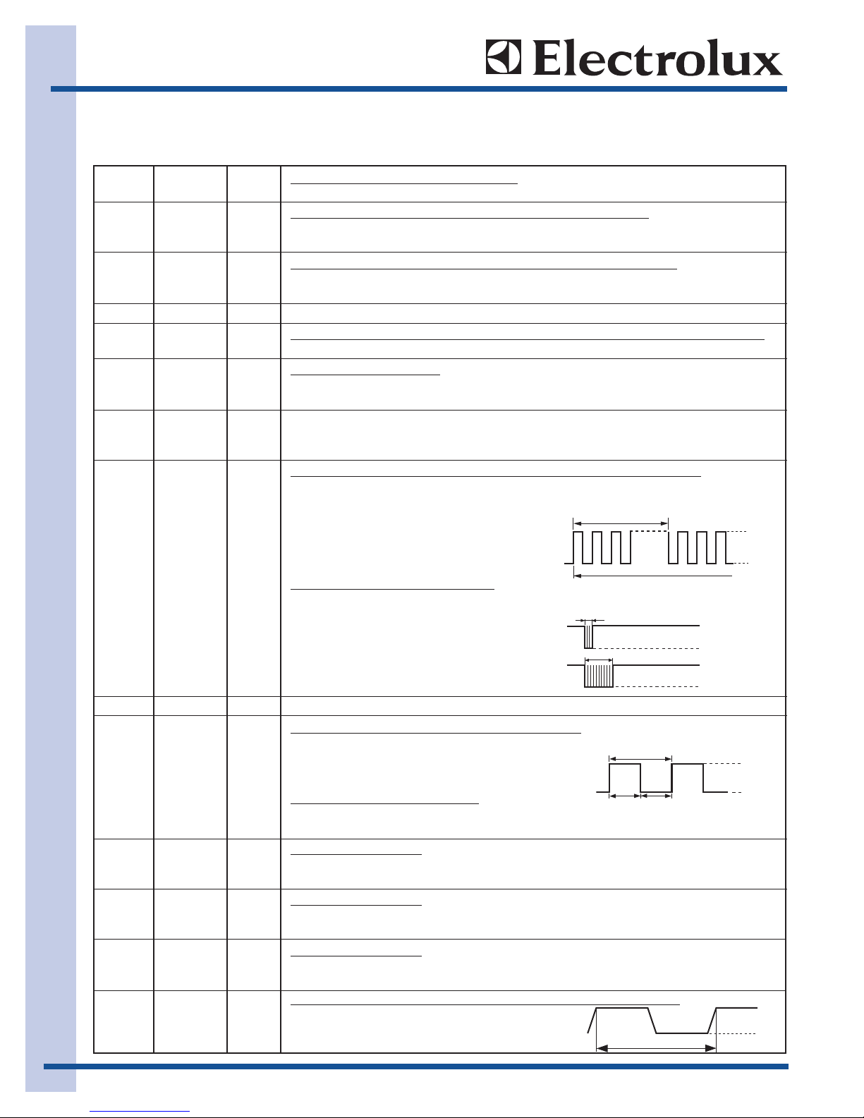
Description of LSI
LSI
The I/O signal of the LSI is detailed in the following table.
Pin No. Signal I/O Description
1-2 VL2-VL1 IN Power source voltage input terminal.
Standard voltage for LCD.
3-5 AN7-AN5 IN Terminal to change cooking input according to the Model.
By using the A/D converter contained in the LSI, DC voltage in accordance with the
Model in operation is applied to set up its cooking constant.
6 AN4 IN Temperature measurement input: MAGNETRON THERMISTOR.
By inputting DC voltage corresponding to thetemperature detected by the thermistor,
this input is converted into temperature by the A/D converter built into the SLI.
7 AN3 OUT Back light circuit(Light emitting diodes) driving signal.
8 AN2 IN To input signal which communicates the door open/close information to LSI.
Door close “H”level signal (0V). Door open “L”level signal (-5V).
9 AN1 IN Humidity sensor input f
This input is an analog input terminal from the humidity sensor circuit, and connected
to the A/D converter built into the LSI.
10 AN0 IN Used for initial balancing of the bridge circuit (humidity sensor). This input is an analog
input terminal from the humidity sensor circuit, and connected to the A/D converter
built into the LSI
11 P57 OUT Oven lamp, fan motor stirrer motor and inverter unit driving signal
To turn on and off shut off relay (RY 1). The
square waveformvoltage is delivered to the
RY1 driving circuit.
16.7 msec.
H : GND
During cooking
12 P56 OUT Signal to sound buzzer (2.0 kHz).
A: key touch sound.
B: Completion sound.
0.1 sec.
A
2.0 sec.
B
13 P50 OUT Terminal not used.
14-18 P54-P50 OUT Used for initial balancing of the bridge circuit (humidity sensor)
19 P47 OUT Power level data output signal for inverter unit.
The power level will be decided by the time ratio
16.7 msec.
of T1 and T2.
20 P46 IN Signal coming from touch key.
T1
When either G1 line on key matrix is touched, a correspondingsignal out of P20 - P27
will be input into P46. When no key is touched, the signal is held at “H”level.
21 P45 IN Signal similar to P46.
When either G2 line on key matrix is touched, a corresponding signal will be input into
P45.
22 P44 IN Signal similar to P46.
When either G3 line on key matrix is touched, a corresponding signal will be input into
P44.
23 P43 IN Signal similar to P46.
When either G4 line on key matrix is touched, a corresponding signal will be input into
P43.
24 INT0 IN
Signal synchronized with commercial power source frequency.
This is the basic timing for time processing of LSI.
T2
16.7 msec.
L : -5V
H : GND
L : -5V
H : GND
L : -5V
H : GND
L : -5V
H : GND
L : -5V
Operation
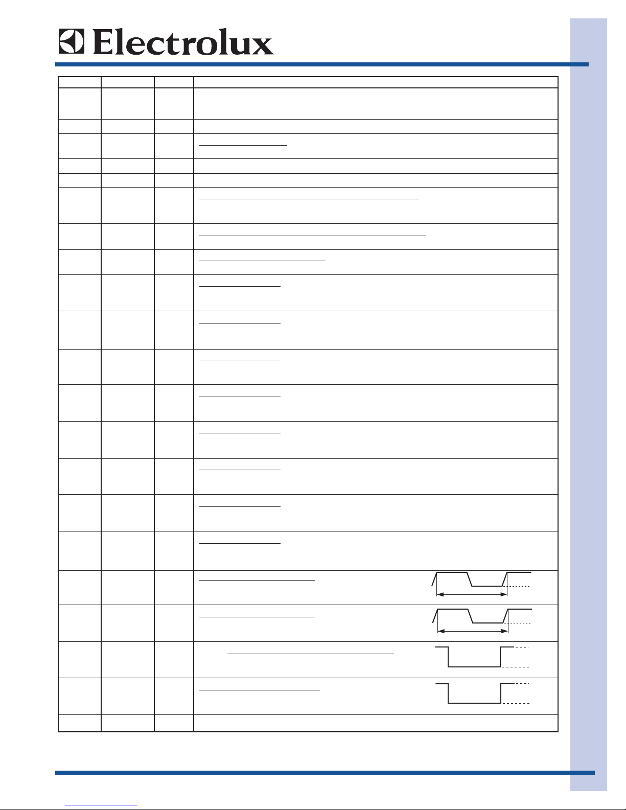
2-9
Pin No. Signal I/O Description
25 P41 OUT Terminal not used.
26 P40 IN Connected to GND through the pull-downresistor.
27 RESET IN Auto clear terminal.
Signal is input to reset the LSI to the initial state when power is applied.
28 P71 OUT Clock signal is output to a memory IC (IC3).
29 P70 OUT Data signal is output to a memory IC (IC3).
30 XIN IN Internal clock oscillation frequency input setting.
The internal clock frequency is set by inserting the ceramic filter oscillation circuit with
respect to XOUT terminal.
31 XOUT OUT Internal clock oscillation frequency control output.
Output to control oscillation input of XIN.
32 VSS IN Power source voltage: -5.0V.
VC voltage of power source circuit input.
33 P27 OUT Key strobe signal.
Signal applied to touch-keysection. A pulse signal is input to P43-P46 terminal while
one of G5 line keys on key matrix is touched.
34 P26 OUT Key strobe signal.
Signal applied to touch-keysection. A pulse signal is input to P43-P46 terminal while
one of G6 line keys on key matrix is touched.
35 P25 OUT Key strobe signal.
Signal applied to touch-keysection. A pulse signal is input to P43-P46 terminal while
one of G7 line keys on key matrix is touched.
36 P24 OUT Key strobe signal.
Signal applied to touch-keysection. A pulse signal is input to P43-P46 terminal while
one of G8 line keys on key matrix is touched.
37 P23 OUT Key strobe signal.
Signal applied to touch-keysection. A pulse signal is input to P43-P46 terminal while
one of G9 line keys on key matrix is touched.
38 P22 OUT Key strobe signal.
Signal applied to touch-keysection. A pulse signal is input to P43-P46 terminal while
one of G10 line keys on key matrix is touched.
39 P21 OUT Key strobe signal.
Signal applied to touch-keysection. A pulse signal is input to P43-P46 terminal while
one of G11 line keys on key matrix is touched.
40 P20 OUT Key strobe signal.
Signal applied to touch-keysection. A pulse signal is input to P43-P46 terminal while
one of G12 line keys on key matrix is touched.
41 P17 OUT Hood lamp driving signal.
To turn on and off relay(RY6). “L”level: During Hood
lamp ON. “H”level: During Hood lamp OFF.
42 P16 OUT Hood lamp driving signal.
To turn on and off relay(RY5). “L”level: During Hood
lamp ON. “H”level: During Hood lamp OFF.
43 P15 OUT Hood motor high / low driving signal.
To turn on and off relay(RY3). “L”level: During Hood
motor high. “H”level: During Hood motor low.
44 P14 OUT Hood motor driving signal.
To turn on and off relay(RY4). “L”level: During Hood
motor on. “H”level: During Hood motor OFF.
45-46 P13-P12 OUT Terminal not used.
ON
ON
16.7 msec.
16.7 msec.
H : GND
OFF
L
H : GND
OFF
L
H : GND
L : -5V
H : GND
L : -5V
 Loading...