

Page 1
Service Mode
165
155
160152025303540
135
140
145
150
105
110
115
120
125
13080859095
100
5
10
Dispenser
4550556065
70
Stemware
PreWash1
PreWash2
HotRinse
MainWash
75
Inlet Valve
Circulation Pump
Drain PumpDrain Pump
Heater
Dry
Heater
Eco
PW1
PW2
ColdRinse2
Heavy
PW1
PW2
PreWash3
ColdRinse1
ColdRinse2
Dispenser
Dry
Dispenser
Dry
Heater
Heater
Heater
Heater
Line Test
MainWash2
MainWash 1
Fast
PW
HotRinse
Rinse
PreWash1
PreWash2
4550556065
70
Dispenser
5101520253035
40
Dispenser
Dispenser
51015
ColdRinse
Dry
HotRinse
HotRinse
51015
Dry
PreWash
MainWash
PW4
PreWash3
MainWash
ColdRinse1
HotRinse
MainWash
Heater
Dispenser
Upper
Dispenser
PW1
PW2CRHotRinse
Heater
Normal/Auto
PW
MainWash
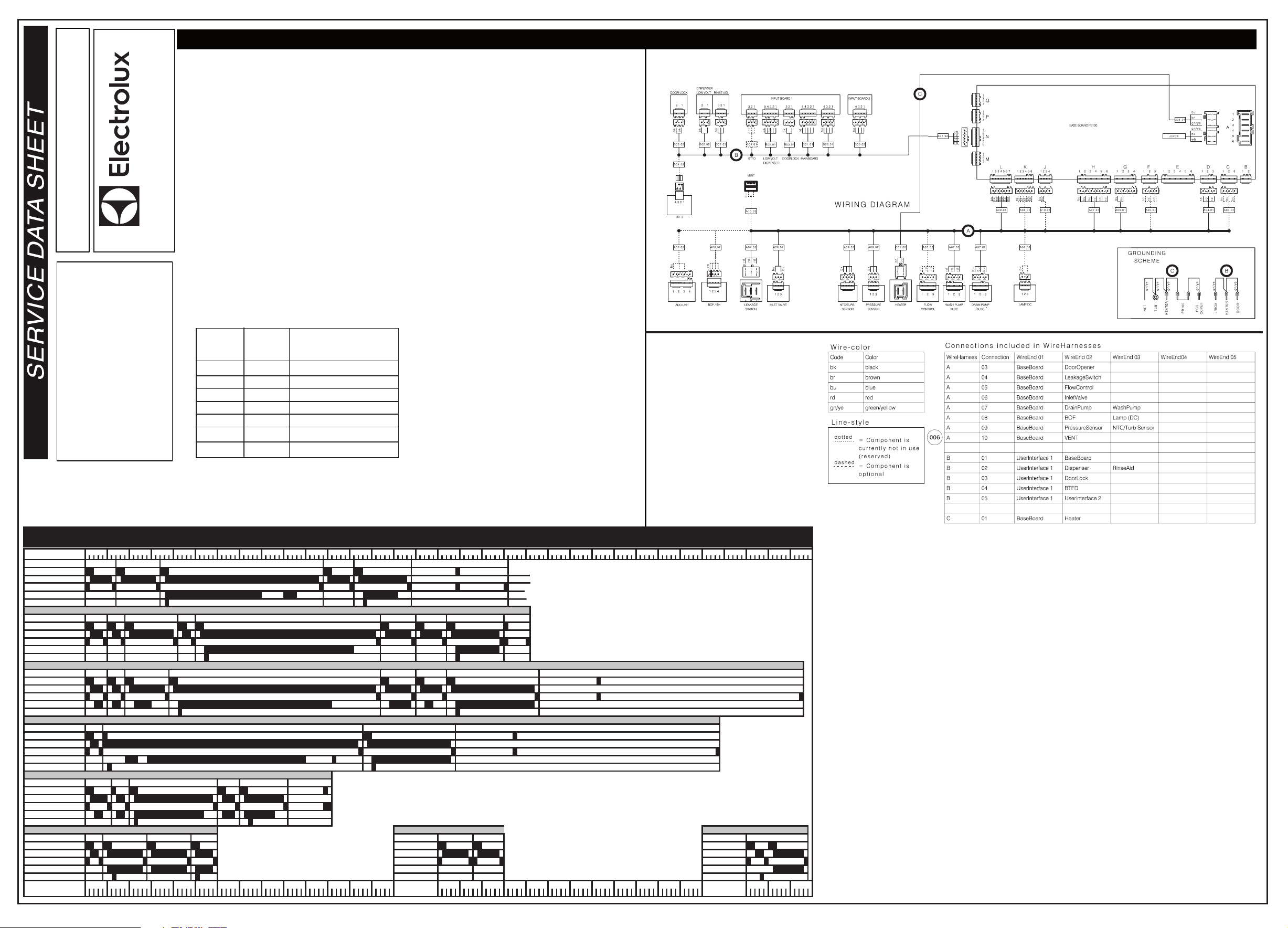
Wiring Diagram
P/N: 808936683
SERVICE DATA SHEET
This information is intended for use by
persons having electrical and
mechanical training and a level of
considered acceptable in the appliance
repair trade. Electrolux Home Products
knowledge of these subjects generally
North America cannot be responsible,
After Cancel, press pad Heavy and Fast simultaneously for
at least 4 seconds to access Service Mode.
LED Auto, Led Heavy and Led Normal blink to indicate
that Service mode is accesed.
After accessed Service mode ( Led Auto, Led Heavy and
Led Normal blinking):
1. Press pad Auto to show the first alarm code.
- Led Auto blinks to indicate the machine is in Alarm
Reading.
- The first alarm code saved is shown in the display. For
descriptions of alarm codes, please see Alarm Codes
section.
2. Press pad Auto again to show the second alarm code.
3. Press pad Auto once more to show the third alarm
EI 24ID81
code.
4. Press pad Auto the fourth time to move to Actuator Test.
Press pad repeatedly will sequentially turn on one
actuator at a time.
- Led Auto is turned off. led Heavy blincks to indicate the
machine is in Actuator Test.
- The actuator number is shown in the display, see the follo wing table for details.
damag e of any kind arising from the
use of this Service Data Sheet.
nor assume any liability, for injury or
Number of
pad Heavy
pressed
4
5
6
7
8
9
10
Actuator
Number
in display
4
5
6
7
8
9
10
LED Test/Delete Alarm Memory
After accessed Service mode ( Led Auto, Led Heavy and
Led Normal blinking):
1. Press pad Heavy to start this function.
- All LEDS and display blinks 5 seconds on 1 second off.
- Buzzer beeps 5 seconds and then off.
- The alarm codes saved in memory are erased.
2. The mode can be exit by pressing the CANCEL button,
or waiting 60 seconds after last button pressing.
Functional Test cycle
After accessed Service mode (Led Auto, Led Heavy and
Led Normal blinking):
1. Press pad Normal to start the test cycle.The cycle will not
start if door is opened.
- LED Normal blinks all the way through the whole cycle,
even if after the cycle is finished
The test cycle runs as a normal wash cycle.
It can be cancelled or run to its end.
Actuator
Regeneration Valve
Drain Pump
Inlet Valve
Heater
Wash pump
Dispenser
Dry Fan
Minutes
Inlet Valve
Inlet Valve
Circulation Pump
Circulation Pump
Drain Pump
Inlet Valve
Inlet Valve
Circulation Pump
Circulation Pump
Drain Pump
Inlet Valve
Inlet Valve
Circulation Pump
Circulation Pump
Drain Pump
5. Press pad Auto when actuator number 10 is activated,
the machine will cycle back to Alarm reading and show
the first alarm code saved.
6. The mode can be exit by pressing the CANCEL button,
or waiting 60 seconds after last button pressing.
Cycle Selection Options
Cycle
Normal Cycle (with light soil)
Selection Options
Circulation Pump
Circulation Pump
Circulation Pump
Circulation Pump
Minutes
Inlet Valve
Inlet Valve
Drain Pump
Inlet Valve
Inlet Valve
Drain Pump
Cycles may differ in behaviour from presentation above due to the dependence of turbidity,
temperature and user input. E.g. Less/more phases; shorter/longer duration.
Inlet Valve
Circ. Pump
Drain Pump
Minutes
Inlet Valve
Circ. Pump
Drain Pump
Minutes
Page 2
Tub Gasket
Operation
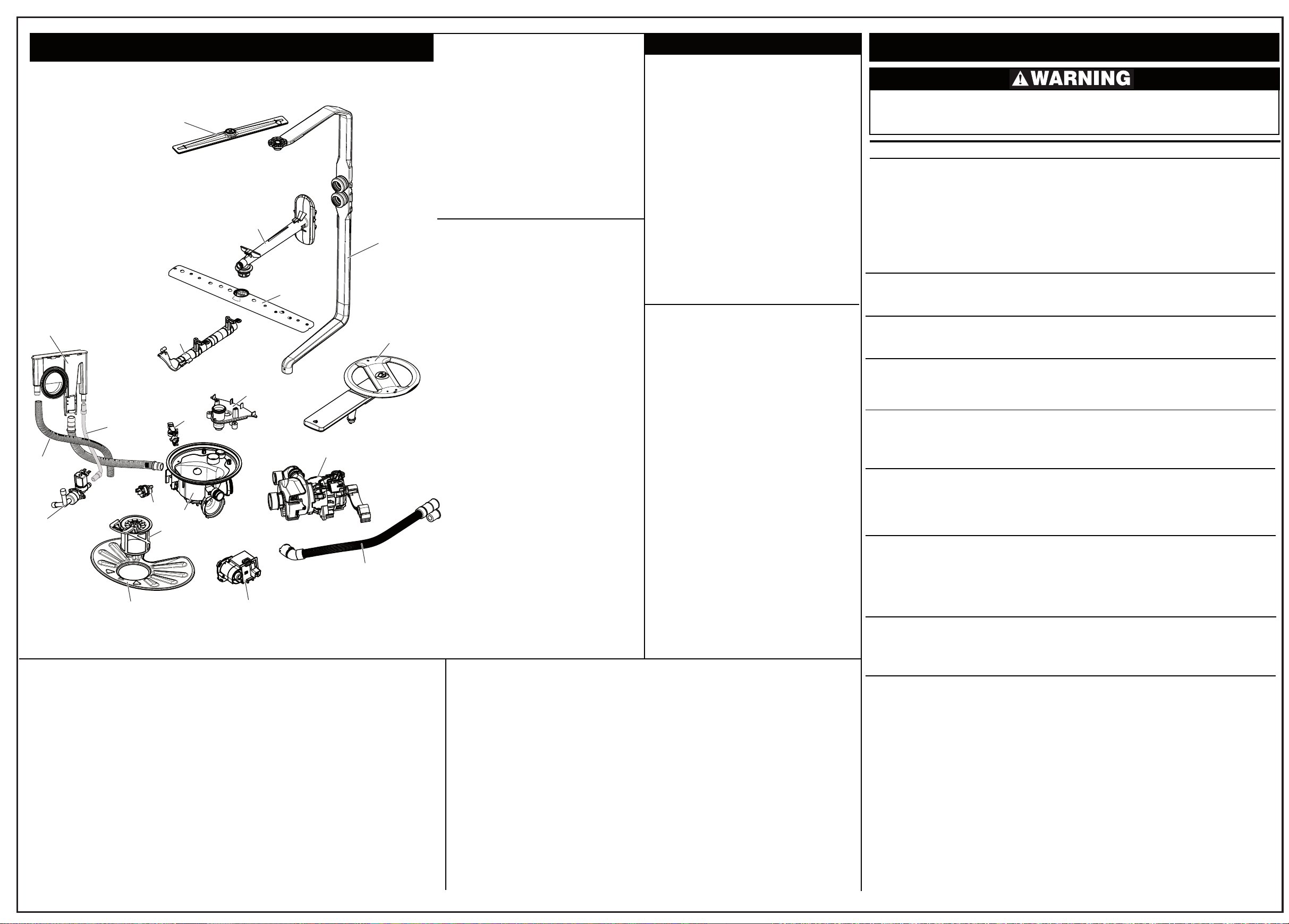
Trouble Shooting TipsExploded View of Wash System
Small Tank
Hose Tank
Sump
Inlet Valve
Valve Tank
Hose
Coarse Filter
Upper Spray arm
Flex Wash
Manifold
Turbidity
Fine
Filter
Pressure
Sensor
Sump
Manifold
Middle Spray Arm
Lower Spray Arm
Support
Drain Pump
Delivery Tube
Lower Spray Arm
Circulation Motor
and Heater Assembly
Drain Hose
The door gasket is pressed into the tub channel
for an interference fit. To install the gasket:
1. Press the gasket across the header using
your hands.
2. Press the gasket while stretching around
the corners .
NOTE: There should be no wrinkles or
puckers in the corners.
3. Place the gasket end at the bottom and
then press the gasket in from the bottom up.
Detergent and Rinse Aid Dispenser
The detergent and rinse aid dispenser is a one
piece component consisting of a molded
detergent cup and a built-in rinse aid dispenser.
The detergent cup has a spring loaded cover
and the rinse aid dispenser has a cover.
Liquid rinse aid is added to the dispenser up to
the fill line indicator. The amount of rinse aid
released can be adjusted from 1, being the
least amount, to 4, being the greatest amount.
To replace dispenser:
• shut off electricity to dishwasher,
• remove outer door panel assembly,
• disconnect wiring to the actuator,
• remove the six screws,
• remove the dispenser,
• replace and reinstall screws,
• rewire actuator.
Starting a Cycle Open door,select the cycle and options: then
Delay Start Open door
Cancelling a
cycle
Selecting a new
cycle or option Open door, select the desired cycle and
Locking Controls Open door and hold down the “air dry” pad
press the “ST
selected cycle pad will then flash. Close the
door and the cycle will begin.
press the “DELA
pad will increase the delay time by 1 hour
(1 to 24 hours).
Open the door
until a tone is heard.
options; then press the “START” pad and
close the door. The cycle will begin.
for 5 seconds.
“loc” and the pads will be unresponsive.
To unlock the control hold the “AIR DRY”
pad down for 5 seconds until “loc goes out.
Normal function will resume.
ART” pad. The LED over the
,select the cycle and options; then
Y” pad. Each press of the
, press the “CANCEL” pad
The status window will display
Alarm Codes/Description
Code Description
family
i10 Water Tap Closed
i20 Draining Problem
i30 Aqua Control
i40 Analogue pressure sensor problem
i50 Washing Motor Problem
i60 Heating Element Problem
i70 Thermistor problem
i80 Auto Door Opener
i90 Configuration Problem
iB0 Sensor Problem
iC0 Communication problem
iD0 Tacho problem
Personal Injury Hazard
Always disconnect the dishwasher from the electrical power source before adjusting or
replacing components.
Symptom
Dishwasher will not operate when
turned on.
Motor hums but will not start or run.
Motor trips out on internal thermal
overload protector.
Dishwasher runs but will not heat.
Detergent cover will not latch or
open.
Dishwasher will not pump out.
Dishwasher will not fill with water.
Check the Following
1. Fuse (blown or tripped).
2. 120 VAC supply wiring connection
faulty.
3. Electronic control board defective.
4. No 12 VAC power to control.
5. Motor (inoperative).
6. Door switch (open contacts).
7. Door latch not making contact with
door switch.
8. Touch pad circuit defective.
9. No indicator lamps illuminate when
START or OPTIONS are pressed.
1. Motor (bad bearings).
2. Motor stuck due to prolonged
non-use.
1. Improper voltage.
2. Motor windings shorted.
3. Glass or foreign items in pump.
1. Heater element (open).
2. Electronic control board defective.
3. Wiring or terminal defective.
4. Hi-Limit thermostat defective.
1. Latch mechanism defective.
2. Electronic control board defective.
3. Wiring or terminal defective.
4. Broken spring(s).
5. Defective actuator.
1. Drain restricted.
2. Electronic control board defective.
3. Defective drain pump.
4. Blocked impeller.
5. Open windings.
6. Wiring or terminal defective.
7. Defective Drain Valve. 7. Repair or replace.
1. Water supply turned off.
2. Defective water inlet fill valve.
3. Check fill valve screen for
obstructions.
4. Defective float switch.
5. Electronic control board defective.
6. Wiring or terminal defective.
7. Float stuck in “UP” position.
Remedy
1. Replace fuse or reset breaker.
2. Repair or replace wire fasteners at
dishwasher junction box.
3. Replace control board.
4. Replace control board.
5. Replace motor/impeller assembly.
6. Replace latch assembly.
7. Replace latch assembly.
8. Replace console assembly.
9. Replace console assembly.
1. Replace motor assembly.
2. Rotate motor impeller.
1. Check voltage.
2. Replace motor/impeller assembly.
3. Clean and clear blockage.
1. Replace heater element.
2. Replace control board.
3. Repair or replace.
4. Replace thermostat.
1. Replace dispenser.
2. Replace control board.
3. Repair or replace.
4. Replace dispenser.
5. Replace dispenser.
1. Clear restrictions.
2. Replace control board.
3. Replace pump.
4. Check for blockage, clear.
5. Replace pump assembly.
6. Repair or replace.
1. Turn water supply on.
2. Replace water inlet fill valve.
3. Disassemble and clean screen.
4. Repair or replace.
5. Replace control board.
6. Repair or replace.
7. Clean or replace float.
Pump Assembly
The circulation pump is driven by a brushless-sensorless AC-motor. When looking into
the inlet hose, the impeller rotates by the
permanent magnet rotor in the counter-clockwise direction when 3-phase power
is applied by the main board electronics.
When the motor drives the pump approximately at 2900 rpm, supplying 100% filtered
water at a rate of approximately 17 GPM to
all three spray arms at once.
Draining is accomplished by using a smaller,
separate, 3-phase brushless-sensorless drain
pump motor mounted to the sump. The drain
pump is connected to the sump directly.
Speed is 2800rpm, controlled by the main
board electronics.
A rubber check valve flap is inserted at the
discharge end of the drain outlet pipe, which is
integrated on the sump.
A raised drain hose loop section is routed on
the side of the unit to help prevent/limit back
flow out of the dishwasher. No additional such
loops are required.
The main circulation pump is removed by
disconnecting both attached clamps and
hoses, disconnecting the wiring harness to the
pump assembly and un-strapping the pump
out of the rubber mount in the basement. Wire
harness connections include 2 earth tabs,
motor connector and heater connector.
Product Specifications
Electrical
Rating ...................................120 Volts, 60Hz
Separate Circuit..15 amp min.- 20 amp max.
Motor (Amps)
Heater Wattage ..................................... 850
Total Amps (load rated) ......................... 13.0
Water Temps controlled ......................... ±5°F
To assure success have outer door in place
TempAssure (cycle dependent)
Hi-TempAssure: 140°F Wash/149°F Final
Rinse
SanitizeAssure: 140°F Wash/156°F Final
Rinse
Hi-Limit Thermostat ................. 200°F (93°C)
............................................0.4
Main Wash: 140°F
Final Wash: 140°F
iE0 Flow controller problem
iF0 Water level problem
Water Supply
Suggested minimum incoming water
temperature ............................. 120°F (49°C)
Pressure (PSI) min./max...................... 20/90
Connection (GHT) ........................3/4" 11.5NH
Consumption (Normal Cycle) .......................
............. 3.1 - 7.4 U.S. gal., 11.5 - 28.1 liters
Water valve flow rate (U.S. GPM) ........... 0.66
Water recirculation rate (U.S. GPM) ..............
............................... approx. 17 (@2900rpm)
Water fill time ................................... 104 sec.
Dishwasher water siphons out.
Detergent left in dispenser.
1. Drain hose (high) loop too low.
2. Drain line connected to a floor drain
not vented.
3. Drain valve or pump stuck open.
1. Detergent allowed to stand too long in
dispenser.
2. Dispenser wet when detergent
added.
3. Detergent cover held closed or blocked
by large dishes.
4. Improper incoming water
temperature to properly dissolve
detergent.
5. Spray arm blocked.
6. Is water getting into unit.
Note: See "Detergent cover will not latch or open."
was
1. Repair to proper
height
.
2. Install air gap at counter top.
3. Repair or replace.
1. Instruct customer/user.
2. Instruct customer/user.
3. Instruct customer/user on proper
loading of dishes.
4. Incoming water temperature of
120°F is required to properly
dissolve dishwashing detergents.
5. Instruct customer/user.
6. Check fill valve repair or replace.
32-inch minimum
808936683 -A 26/2016
 Loading...