

Page 1
EN WINE COOLER/BEVERAGE CENTER
FR REFROIDISSEUR DE VIN/ CENTRE
DE BOISSONS
ES REFRIGERADOR DE VINO/ CENTRO
DE BEBIDAS
USE AND CARE GUIDE
GUIDE D’UTILISATION ET D’ENTRETIEN
GUIA DE USO Y CUIDADO
A16345301 June 2019
Page 2
2
Finding Information
Please Read and Save
This Guide
Thank you for choosing Electrolux, the
new premium brand in home appliances.
This Use & Care Guide is part of our
commitment to customer satisfaction and
product quality throughout the service life
of your new Wine Cooler/Beverage Center.
We view your purchase as the beginning
of a relationship. To ensure our ability to
continue serving you, please use this page
to record key product information.
IMPORTANT
PLEASE READ all instructions
completely before attempting to install
or operate the unit.
All Wine Cooler/Beverage Centers
require a connection to an electrical
power source. Improper hook-up can
result in a safety hazard and potential
damage to the product or contents!
Proper installation, in accordance with
the manufacturer’s specifications and all
local codes, is the sole responsibility of
the consumer. The manufacturer is not
responsible for any installation expenses
or damages incurred due to improper
installation. If you are unsure of your
ability to safely connect electric power to
the unit, consult a licensed and insured
professional to perform all electrical
work.
Once you have your unit installed,
we suggest you keep this manual
in a safe place for future reference.
Should any problems occur, refer to the
“Troubleshooting” section of this manual.
This information will help you quickly
identify a problem and get it remedied. In
the event you require assistance, please
contact the dealer where you purchased
your unit.
Make a Record for Quick
Reference
Whenever you call to request information
or service, you will need to know your
model number and serial number. You
can find this information on the serial plate
located in the top left hand corner of your
unit and on the product registration card.
NOTE
Registering your product with Electrolux
enhances our ability to serve you. You
can register online at
www.electroluxappliances.com or by
dropping your Product Registration
Card in the mail. Complete and mail the
Product Registration Card as soon as
possible to validate the registration date.
Product Registration
Card
The package containing this manual
also includes your product registration
information. Warranty coverage begins at
the time your Electrolux wine cooler was
purchased.
Please record the purchase date of your
Electrolux unit and your dealer’s name,
address and telephone number.
____________________________________
Purchase Date
____________________________________
Electrolux Model Number
____________________________________
Electrolux Serial Number
____________________________________
Dealer Name
____________________________________
Dealer Address
____________________________________
Dealer Telephone
Page 3

Finding Information
3
Keep this manual and the sales receipt
together in a safe place for further
reference.
Questions?
For toll-free telephone support in the U.S.
and Canada:1-877- 4ELECTROLUX
(1-877-435-3287)
For online support and Internet product
information: www.electroluxappliances.com
Table of Contents
Finding Information ................................. 2
Safety ..................................................... 4
Feature Overview .................................... 7
Installation .............................................. 8
Leveling ................................................ 14
Operation ............................................. 15
Door Reversal ....................................... 18
Storage ................................................ 20
Care & Maintenance ............................. 21
Troubleshooting .................................... 22
Warranty Information ............................ 23
Page 4
4
Safety
Important Safety
Instructions
Safety Precautions
Do not attempt to install or operate
your unit until you have read the safety
precautions in this manual. Safety items
throughout this manual are labeled with a
Danger, Warning or Caution based on the
risk type.
Definitions
This is the safety alert symbol. It is
used to alert you to potential personal
injury hazards. Obey all safety messages
that follow this symbol to avoid possible
injury or death.
DANGER
DANGER indicates an imminently
hazardous situation which, if not
avoided, will result in death or serious
injury.
WARNING
WARNING indicates a potentially
hazardous situation which, if not
avoided, could result in death or serious
injury.
CAUTION
CAUTION indicates a potentially
hazardous situation which, if not
avoided, may result in minor or
moderate injury.
IMPORTANT
Indicates installation, operation, or
maintenance information which is
important but not hazard-related.
General Precautions
WARNING
RISK OF CHILD ENTRAPMENT. Before
you throw away your old appliance, take
off the doors and leave shelves in place
so that children may not easily climb
inside.
WARNING
• Never attempt to repair or perform
maintenance on the unit until the
electricity has been disconnected.
• Altering, cutting of power cord, removal
of power cord, removal of power plug,
or direct wiring can cause serious
injury, fire and/or loss of property and/
or life and will void the warranty.
• Do not lift unit by door handle.
CAUTION
• Use care when moving the unit. Some
edges are sharp and may cause
personal injury. Wear gloves when
moving or repositioning the unit.
• Never install the unit behind closed
doors. Be sure front grille is free of
obstruction. Obstructing free air flow
can cause the unit to malfunction,
and may void the warranty.
• Allow unit temperature to stabilize
for 24 hours before use.
CAUTION
Use only genuine Electrolux replacement
parts. Imitation parts can damage the
unit and may void the warranty.
WARNING
WARNING! CALIFORNIA RESIDENTS
Cancer and Reproductive Harm
www.P65Warnings.ca.gov
Page 5

DANGER
DANGER Risk of fire or explosion.
Flammable refrigerant used. Do not
use mechanical devices to defrost
refrigerator. Do not puncture refrigerant
tubing.
DANGER Risk of fire or explosion.
Flammable refrigerant used. To be
repaired only by trained service
personnel. Do not puncture refrigerant
tubing.
CAUTION
CAUTION Risk of fire or explosion.
Flammable refrigerant used. Consult
repair manual/owner’s guide before
attempting to service this product. All
safety precautions must be followed.
CAUTION Risk of fire or explosion.
Dispose of property in accordance with
federal or local regulations. Flammable
refrigerant used.
CAUTION Risk of fire or explosion
due to puncture of refrigerant tubing.
Follow handling instructions carefully.
Flammable refrigerant used.
WARNING
Do not use electrical appliances inside
the food storage compartments of the
appliance, unless they are of the type
recommended by the manufacturer.
Child Safety
• This appliance is not intended for use
by persons (including children) with
reduced physical, sensory or mental
capabilities, or lack of experience
and knowledge, unless they have
been given supervision or instruction
concerning use of the appliance by a
person responsible for their safety.
• Destroy carton, plastic bags, and any
exterior wrapping material immediately
after the Wine Cooler/Beverage
Center is unpacked. Children should
never use these items to play. Cartons
covered with rugs, bedspreads, plastic
sheets or stretch wrap may become
Safety
airtight chambers, and can quickly
cause suffocation.
• Remove all staples from the carton.
Staples can cause severe cuts, and
destroy finishes if they come in contact
with other appliances or furniture.
• An empty, discarded Wine Cooler/
Beverage Center is a very dangerous
attraction to children.
• Remove the door(s) of any appliance
that is not in use, even if it is being
discarded.
Proper Disposal of your Wine
Cooler/Beverage Center
Risk of child entrapment
Child entrapment and suffocation are
not problems of the past. Junked or
abandoned Wine Coolers/Beverage
Centers are still dangerous – even if they
will sit for “just a few days”. If you are
getting rid of your old unit, please follow
the instructions below to help prevent
accidents.
We strongly encourage responsible
appliance recycling/disposal methods.
Check with your utility company or visit
www.recyclemyoldfridge.com for more
information on recycling your old Wine
Cooler/Beverage Center.
Before you throw away your old Wine
Cooler/Beverage Center:
• Remove doors.
• Leave shelves in place so children may
not easily climb inside.
• Have refrigerant removed by a
qualified service technician.
5
Page 6
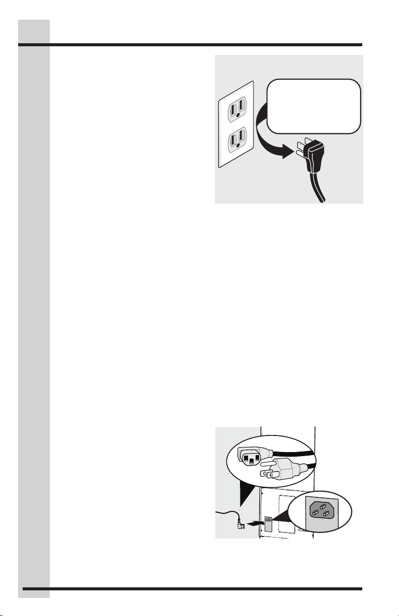
Grounding type wall receptacle
Power cord with
3-prong grounded plug
Do not, under
any circumstances,
cut, remove,
or bypass the
grounding prong.
6
Safety
Electrical Information
• The Wine Cooler/Beverage Center
must be plugged into its own
dedicated 115 Volt, 60 Hz., 15 Amp,
AC only electrical outlet. The power
cord of the appliance is equipped
with a three-prong grounding plug
for your protection against electrical
shock hazards. It must be plugged
directly into a properly grounded three
prong receptacle. The receptacle
must be installed in accordance with
local codes and ordinances. Consult a
qualified electrician. Avoid connecting
refrigerator to a Ground Fault
Interruptor (GFI) circuit. Do not use an
extension cord or adapter plug.
• If the power cord is damaged, it
should be replaced by an authorized
service technician to prevent any risk.
• Never unplug the wine cooler by
pulling on the power cord. Always
grip the plug firmly, and pull straight
out from the receptacle to prevent
damaging the power cord.
• Unplug the Wine Cooler/Beverage
Center before cleaning and before
replacing a light bulb to avoid electrical
shock.
• Performance may be affected if
the voltage varies by 10% or more.
Operating the Wine Cooler/Beverage
Center with insufficient power can
damage the compressor. Such
damage is not covered under your
warranty.
• Do not plug the unit into an electrical
outlet controlled by a wall switch or
pull cord to prevent the Wine Cooler/
Beverage Center from being turned off
accidentally.
This appliance is intended to be used in
household and similar applications such
as:
• Staff kitchen areas in shops, offices
and other working environments
• Farm houses and by clients in hotels,
motels and other residential type
environments
• Bed and breakfast type environments
• Catering and similar non-retail
applications
• The appliance shall not be exposed
to rain
To connect your unit:
1 Locate Power cord box inside unit.
2 Remove Power cord from box and
insert the plug into the electrical box
on the back of the appliance.
3 Connect the plug to electrical source.
Page 7
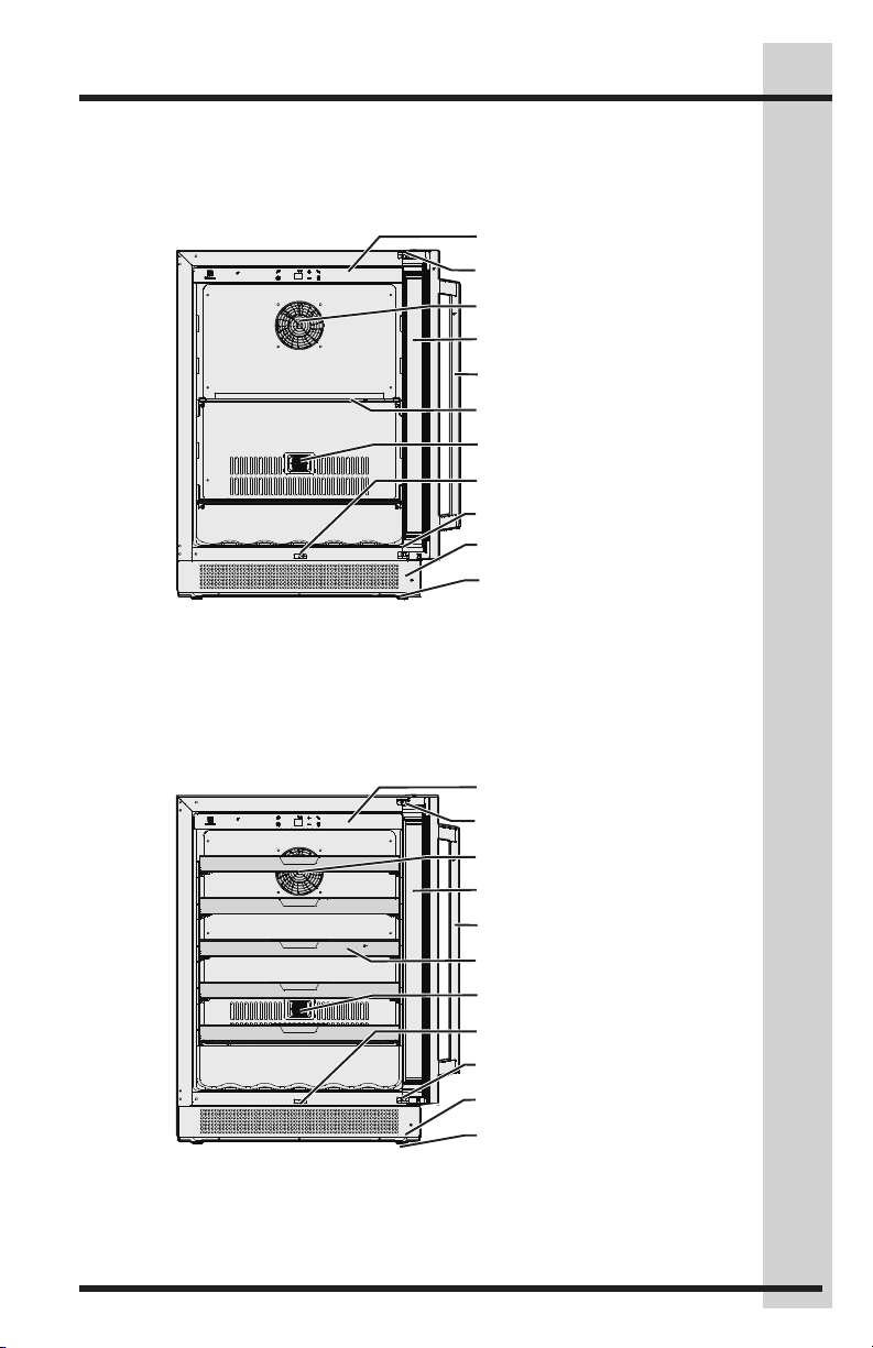
Feature Overview
Beverage Center
Control Panel
Upper Hinge
Fan
Door
Handle
Shelf
Sensor
Door Light Switch
Lower Hinge
Toe Grille
Leg
7
Wine Cooler
Control Panel
Upper Hinge
Fan
Door
Handle
Shelf
Sensor
Door Light Switch
Lower Hinge
Toe Grille
Leg
Page 8

8
Installation
Installation of Your Wine
Cooler / Beverage Center
Your Electrolux Wine Cooler/Beverage
Center has been designed for either freestanding or under counter installation.
When under counter, your unit does not
require additional air space for top, sides
or rear. In either case, the front grille must
NOT be obstructed.
• This appliance is designed to be for
free standing installation or under
counter (fully recessed). (Refer to
sticker located on the back of this
appliance.)
• This appliance is intended to be used
exclusively for the storage of wine or
beverages.
• Place your Wine Cooler/Beverage
Center on a floor that is strong enough
to support it when it is fully loaded.
To level your Wine Cooler/Beverage
Center, adjust the front leveling legs at
the bottom of the unit.
• This appliance uses flammable
refrigerant. So never damage
the cooling pipe work during the
transportation.
• Locate the Wine Cooler/Beverage
Center away from direct sunlight and
sources of heat (stove, heater, radiator,
etc.). Direct sunlight may affect the
acrylic coating and heat sources
may increase electrical consumption.
Extreme cold ambient temperatures
may also cause the unit not to perform
properly.
• Avoid locating the unit in moist areas.
• Plug the Wine Cooler/Beverage Center
into an exclusive, properly installed,
grounded wall outlet. Do not under
any circumstances cut or remove the
third (ground) prong from the power
cord. Any questions concerning power
and/or grounding should be directed
toward a certified electrician or an
Authorized Products Service Center.
NOTE
To ease unit installation and removal, it
is recommended that the cabinet rough
opening dimensions be increased by at
least ¼ inch over the dimensions given
for your unit.
NOTE
All units require zero clearance when
installed flush with a cabinet or wall.
Electrolux stainless steel models require
a minimum 2-7⁄8 inch handle clearance
when installed against a wall or cabinet
that extends beyond the front edge of
the unit.
Before Using Your Wine Cooler/
Beverage Center
• Remove the exterior and interior
packing.
• Before connecting the Wine Cooler /
Beverage Center to the power source,
let it stand upright for approximately 2
hours. This will reduce the possibility
of a malfunction in the cooling system
from handling during transportation.
• Clean the interior surface with
lukewarm water using a soft cloth.
Using your Wine Cooler/Beverage
Center
• Store wine in sealed bottles.
• Do not overload the cabinet.
• Do not open the door unless
necessary.
• Do not cover shelves with aluminum
foil or any other shelf material which
may prevent air circulation.
Page 9

Installation
9
Installing the Anti-Tip
Bracket
CAUTION
If your Wine Cooler/Beverage Center
is not located under a counter top
(free standing), you must use an
anti-tip bracket installed as per these
instructions. If the Wine Cooler/
Beverage Center is removed from its
location for any reason, make sure that
the bracket is properly engaged when
you push the Wine Cooler/Beverage
Center back into the original location.
If the bracket is not properly engaged,
there is a risk of the Wine Cooler/
Beverage Center tipping over, causing
property or personal injury if you or a
child stand, sit, or lean on an open shelf.
CAUTION
Any finished flooring should be
protected with appropriate material to
avoid damage when moving the unit.
ALL UNITS CAN TIP
NOTE
While performing installation described
in this section, gloves, safety glasses, or
goggles should be worn.
WARNING
This appliance may tip when shelves
are extended, causing damage or
injury. If this appliance is used in a FREE
STANDING application, the anti-tip
bracket must be installed following these
instructions!
IMPORTANT
Determine the final location of the
appliance before attempting to install
the bracket. You will need to choose
one of the three installation methods
below.
Installation methods:
1. DRYWALL
2. WOOD FLOOR
3. CONCRETE FLOOR
Anti-tip bracket installation
The bracket can be installed at the left
bottom OR right bottom of the back of
the unit. You can choose which side is
convenient for you.
Tools you will need:
Gloves
Safety
goggles
Hammer
or Mallet
Stud
finder
Electric drill
3/8" drill bit
with
Screwdriver
Wrench
Page 10

10
Installation
DRYWALL installation:
A
1
Bracket
1. After you have chosen the installation
location, place the bracket on the floor
with (1) against the wall, use Screw
(E) (2 pcs) to secure the bracket to
the wall. Ensure at least one screw is
secured into a stud.
2. Align lower corner of unit and bracket
slot (A), secure with hexagon bolt (B),
lock washer (C) and flat washer (D).
Hexagon Bolt
B
1/4" x 1.2" (1 pc)
C
Lock Washer (1 pc)
D
Flat Washer (1 pc)
Screw
E
ST4x35 (2 pcs)
IMPORTANT
The screws MUST enter into a wood
stud. If the wall contains metal studs
or similar materials, then the floor
installation must be used.
A
D
C
WOOD FLOOR installation:
A
2
Bracket
1. After you have chosen the installation
location, place the bracket on the
wood floor. Use Screw (E) (2 pcs) to
secure bracket to floor using bracket
holes (2).
2. Align lower corner of unit and bracket
slot (A), secure with hexagon bolt (B),
lock washer (C) and flat washer (D).
Hexagon Bolt
B
1/4" x 1.2" (1 pc)
C
Lock Washer (1 pc)
D
Flat Washer (1 pc)
Screw
E
ST4x35 (2 pcs)
A
D
C
B
E
Wall stud
B
E
Page 11

Installation
11
CONCRETE FLOOR installation:
A
3
Bracket
1. After you have chosen the installation
location, use either hole (3) to secure
the bracket into the concrete floor.
2. Using a concrete bit, drill 8mm (3/8”)
pilot hole 45mm (1.7”) deep.
3. Remove the nut, lock washer and
washer from the expansion screw (F).
4. Carefully tap the expansion screw
into the concrete, using a hammer or
mallet.
5. Align bracket hole (3) over the
expansion screw threads and replace
washer (D), lock washer (C) and nut
back on the expansion screw. Fasten
bracket to the floor by tightening nut
securely.
6. Align lower corner of unit and bracket
slot (A), secure with hexagon bolt (B),
lock washer (C) and flat washer (D).
Hexagon Bolt
B
1/4" x 1.2" (1 pc)
C
Lock Washer (1 pc)
D
Flat Washer (1 pc)
Expansion Screw
F
1/4" x 2.4" (1 pc)
NOTE
If installing on a concrete floor, concrete
fasteners are required, (not included with
the anti-tip kit).
WARNING
TIP OVER HAZARD: One of the rear
cabinet leveling legs must be engaged
under an anti-tip bracket.
WARNING
After installing the bracket, try using light
force to tip the unit. If the unit does not
tip then the bracket is mounted securely.
If the unit does tip, the bracket MUST be
reinstalled following these instructions.
A
D
C
B
F
1.7"
3/8"
Page 12

12
Installation
Installing the Wine Cooler
Your Electrolux wine cooler has been designed for either free-standing or under counter
installation. When under counter, your wine cooler does not require additional air space
for top, sides or rear. In either case, the front grille must NOT be obstructed.
NOTE
To ease unit installation and removal, it is recommended that the cabinet rough
opening dimensions be increased by at least ¼ inch over the dimensions given for
your unit.
NOTE
A minimum of 2 7⁄8 inch handle clearance is recommend for stainless steel models
when installed against a wall or cabinet for door opening/removal of shelves.
24.02"
610mm
24.02"
610mm
34.06"
865mm
875mm
23.82"
605mm
34.45"
23.52"
597.5mm
Page 13

Installation
13
Anti-Tip Installation for
Under Counter
Installation Instructions
1. Remove the anti-tip bracket and
screws from the accessory bag.
NOTE
If the door is being reversed, please take
out the hole plugs from the right hinge
holes.
2. Attach the anti-tip bracket with
screws (2 pcs) in size M5 (12mm)
onto the left hinge holes (if the door
is being reversed, please fix the
anti-top bracket onto the right hinge
holes) and then attach the other end
of the anti-tip bracket onto the niche
with the screws (2 pcs) in size ST4
(12mm).
NOTE
If the door is being reversed, please
attach the anti-tip bracket onto the right
hinge holes and then attach the other
end of the anti-tip bracket onto the
niche with the screws (2 pcs) in size ST4
(12mm).
A
D
Handle Installation
Installation Instructions
1. Place handle over the two mounting
screws (A).
2. Use Allen wrench to tighten 2 set
screws (B) on handle.
A
x2
B
x2
B
x2
x2
E
A Anti-tip bracket (one for right
installation and one for left
installation)
B Screws (2 pcs) Size M5 (12mm)
C Screws (2 pcs) Size ST4 (12mm)
D Kitchen niche
E Product cabinet
C
Page 14

14
Leveling
Leveling the Unit
Position the unit on a flat, level surface capable of supporting the entire weight of the unit
when full.
Leveling Legs
Adjustable legs at the front and rear corners of the appliance should be set so the unit
is firmly positioned on the floor and level from side to side and front to back. The overall
height of your Electrolux appliance may be adjusted between the minimum, 33 ¾”
(85.7cm),by turning the leveling leg in and the maximum, 34 ¾” (88.3cm), by turning the
leveling leg out.
To adjust the leveling legs, place the appliance on a solid surface and protect the floor
beneath the legs to avoid scratching the floor. With the assistance of another person,
lean the appliance back to access the front leveling legs. Raise or lower the legs to the
required dimension by turning the legs. Repeat this process for the rear by tilting the
appliance forward using caution. On a level surface check the appliance for levelness
and adjust accordingly.
Leveling legs, 2
at the front and 2
in the rear.
Front Grille,
keep this area
open.
Page 15

CELLAR
MODE
Wine Cooler
Beverage Center
Operation
15
CELLAR
MODE
Power On/Off (Wine Cooler)
Simultaneously press and hold the Cellar
Mode button and the plus button for 5
seconds to turn the unit power off or on.
When the power is turned back on, the
display will show the previous temperature
settings.
Power On/Off
(Beverage Center)
Press and hold the power
button for 3 seconds.
Temperature Set
Press to decrease/increase the set
temperature. Only the set temperature will
be shown.
NOTE
Set temperature is shown while the
temperature is being changed. Once
complete, current temperature will show
on display.
Lights On/Off
Press once to toggle the lights
ON/OFF. Press and hold for
3 seconds to modify the light
settings, changing between 2
settings. If the current default setting is
‘1A’, press and hold for 3 seconds and
the display will show the ‘2A’ light setting.
Press and hold again to set it back. The
new setting will display for 2 seconds, then
return to show the set temperature.
Lights Behavior
Temperature display shows the light
setting code:
1A: Lights always ON when
door is open; Light always OFF
when door is closed.
2A: Lights always ON no matter
if door is open or closed.
Child Lock
Press and hold for 3 seconds to activate/
deactivate child lock.
Child lock is lit-up when activated.
Child lock disables all button controls.
While in the locked state, you will not be
able to change any display settings until
child lock is deactivated.
Page 16

16
Operation
CELLAR
MODE
Sabbath Mode
Simultaneously press and hold the
increase temperature and decrease
temperature set buttons for 10 seconds to
activate/deactivate Sabbath mode.
When activated, temperature display
shows “Sb” until it is deactivated.
While in Sabbath mode:
• Any button command is disabled apart
from the increase temperature set &
decrease temperature set combination
command to deactivate the Sabbath
mode.
• All lights are turned Off - apart from “Sb”.
• Opening or closing the door will not turn
on or off any lights, digital readouts,
solenoids, fans, valves, compressor,
icons, tones, or alarms. There is a 30
second delay from when the door is
opened until the compressor is allowed
to start or change speed.
Exception: The High/Low Temperature
alerts will be displayed in case of high or
low temperature inside the appliance. The
alert icon turns On, but will not blink, and
it will remain until the Sabbath Mode is
deactivated. An audio alarm will sounds
and automatically turn off after 10 minutes.
When deactivated, temperature display
shows the previous set temperature.
Cellar Mode Set (Wine Cooler Only)
Press once to toggle on and off the cellar
mode.
If the mode is set to Cellaring, the
temperature display shows “CE” until
the Cellaring mode is deactivated. When
deactivated, the previous temperature is
shown.
In Cellaring mode, the temperature is fixed
and cannot be changed from 12ºC/54ºF.
NOTE
Cellar mode temperature is the
recommended temperature for longer
term storage of wine.
C°/F° set
To toggle between
C° and F° settings,
simultaneously press
and hold the increase
button and the light
button.
Page 17

CELLAR
MODE
Demo mode (Wine Cooler)
Simultaneously press and hold the Cellar
Mode & light buttons for 10 seconds to
activate/deactivate Demo mode
When activated, the display shows
alternatively “dE” and “On” for 10 seconds.
Any alert turns off temporarily.
To keep communicating that the machine
is in Demo mode, every few minutes the
display shows alternatively “dE” and “On”
for 10 seconds.
When deactivated, the display shows
alternatively “dE” and “OF” for 10 seconds.
Demo mode (Beverage Center)
Simultaneously press and hold the Mute
Sounds & light buttons for 10 seconds to
activate/deactivate Demo mode
Operation
Mute sounds
Press once to activate/
deactivate. Note that
alarms will not be
muted.
The default setting for
sounds is On. Press
the mute button once
to toggle the display
between ‘OF’ and ‘On’.
The ‘OF’ or ‘On’ will
display for 2 seconds
then the display
switches back to the
previous temperature setting.
When mute sounds is activated, the key
presses are muted, the alarms will still be
active.
High / Low
temperature alert
When the set temp has
been exceeded during
a period of 6 hours,
High Temperature alert
shows “Hº” and blinks
the alert icon.
When the set temp has been insufficient
during a period of 6 hours, Low
Temperature alert shows “Lº” and blinks
the alert icon.
The alerts will not sound in the first 90
minutes after power on.
17
Door open alert
If the door is left open for 5 minutes or
more, the door open icon turns On, the
lights start to blink and an alarm sounds.
Any interaction on the Control panel will
disable the alarms. The icon stays on as
long the door is open.
Page 18

18
5
7
Door Reversal
3
4
6
Reversing the Door
1. To remove the top hinge pin, open
the door and pull down the gasket.
Use a flat screwdriver to pry the hook
out then push up on top hinge pin.
2. Repeat to remove the bottom hinge
pin. Remove door and place on a
padded surface to prevent damage.
CAUTION
Doors are heavy. Two people are recommended to remove or replace the door
assembly from the cabinet.
+
+
+
1
2
5
+
+
+
3. Remove the top hinge screws using a
Phillips head screwdriver.
4. Carefully remove the top screw hole
plugs and move to the opposite side.
5. Remove the lower hinge screws
using a Phillips head screwdriver.
6. Carefully remove the lower screw
hole plugs and move to the opposite
side.
Page 19

Door Reversal
+
+
+
+
19
8
180°
9
10
10
10
11
IMPORTANT
Relocate the door switch
actuator.
7. Install the right top hinge on the left
lower corner.
8. Install the right lower hinge on the left
top corner.
9. Rotate the door 180 degrees (handle
on the right side). Place door on the
left lower hinge. Install the hinge pin
hook then install the hinge pin.
10. Align the door and top hinge. Install
the hinge pin hook then install the
hinge pin.
7
+
+
+
+
12
11. The actuator is on the inside top of
the door and should be relocated to
the bottom of the door.
12. Replace the 2 screws where the
actuator was located at the top of the
door to conceal the remaining holes.
NOTE
After the door reversal process, make
sure the door switch actuator (12) is
installed on the inside bottom of the
door.
Page 20

20
Storage
Wine bottle storage
Only Burgundy and Bordeaux wine bottles
can be loaded on the bottom of the
wine cooler. All other shelves can load
Burgundy, Bordeaux and Champagne
wine bottles. Bottle capacity is 41.
Wine cooler Shelving:
• Five (5) roll-out wine racks
Shelf Removal
Wine Cooler
Open the door completely and pull out
the shelf to the end. Lift up on the front
of the shelf, then on the back part of the
shelf pull slightly forward and lift up to
disconnect the shelf from the rail.
Beverage Center
Open the door completely and push out
the fixing screws on both sides of the
shelf. Continue removing the shelf.
CAUTION
Never try to remove a loaded shelf,
remove everything from the shelf before
moving. Use both hands when moving
the shelf.
Page 21

Care & Maintenance
21
Maintaining Your Wine
cooler
Periodic cleaning and proper maintenance
will ensure efficiency, top performance,
and long life. The maintenance intervals
listed are based on normal conditions. You
may want to shorten the intervals if you
have pets or other special considerations.
Exterior Cleaning for Your
Stainless Steel Model
• Your stainless steel model may
discolor when exposed to chlorine
gas, pool chemicals, salt water, or
cleaners with bleach.
• Keep your stainless unit looking new
by cleaning with a high quality, all-inone stainless steel cleaner/polish on a
monthly basis. Frequent cleaning will
remove surface contamination that
could lead to rust. Some installations
will require cleaning on a weekly basis.
• DO NOT CLEAN WITH STEEL WOOL
PADS.
• DO NOT USE CLEANERS THAT ARE
NOT SPECIFICALLY INTENDED FOR
STAINLESS STEEL (this includes
glass, tile and counter cleansers).
• If any surface discolors or rusting
appears, clean it quickly with Bon-Ami
or Barkeepers Friend Cleanser and a
non-abrasive cloth. Always clean in
the direction of the grain. Always finish
this process with a high quality, all-inone stainless steel cleaner/polish to
prevent further problems.
• USE OF ABRASIVE PADS SUCH AS
SCOTCHBRITE WILL CAUSE THE
GRAINING IN THE STAINLESS TO
BECOME BLURRED.
• Rust that is allowed to linger can
penetrate into the surface of the
stainless steel and become impossible
to remove.
CAUTION
• Stainless steel models exposed to
chlorine gas and moisture such as
areas with spas or swimming pools,
may have some discoloration of
the stainless steel. Discoloration
from chlorine gas is normal. Follow
exterior cleaning instructions.
• NEVER USE CHLORIDE OR
CLEANERS CONTAINING BLEACH
TO CLEAN STAINLESS STEEL.
Interior Cleaning - as Required
1 Disconnect power to the wine cooler.
2 Remove racks if desired.
3 Wipe down the interior with a solution
of non-abrasive mild detergent and
warm water.
4 Rinse with clear water.
5 Reconnect power to the unit.
Should the Wine Cooler/Beverage
Center be stored without use for long
periods:
• Clean thoroughly.
• Leave the door ajar to allow air to
circulate inside the cabinet in order
to avoid possible formations of
condensation, mold or odors.
Page 22

22
Troubleshooting
Before You Call for Service
If the unit appears to be malfunctioning,
read through this manual first. If
the problem persists, check the
Troubleshooting Guide below. Locate the
problem in the guide and refer to the cause
and its remedy before calling for service.
The problem may be something very simple
that can be solved without a service call.
Consulting or contracting a qualified service
technician may be necessary.
If Service is Required
Contact the dealer where you purchased
the unit if service is required. State the
model and serial number and explain the
problem. The model and serial number plate
is located on the ceiling of your unit. If you
do not know the name of the selling dealer
or a local service company, you can check
online at www.electroluxappliances.com or
call 1-877-435-3287.
WARNING
ELECTROCUTION HAZARD
NEVER attempt to repair or perform maintenance on the unit until the main electrical
power has been disconnected.
Problem Possible Cause Remedy
Unit not cold
enough.
Adjust
temperatures
(see “Adjusting
the Temperature”
in the “Start-Up
and Temperature
Control” section).
Unit too cold.
Contents of unit
too cold/frozen.
Adjust temperatures
(see “Adjusting
the Temperature”
in the “Start-Up
and Temperature
Control” section).
No interior light. • Failed LED assembly. • Contact a qualified Electrolux
Light will not go
out when door is
closed.
Alarm(s) will not
shut off.
Power is not restored
after power failure.
Door does not
close properly.
• Control set too warm.
• Light staying on.
• Airflow to front grille
blocked.
• Door gasket not sealing
properly.
• Control set too cold. • Adjust temperature warmer.
• Manual light control is
ON.
• Door switch not making
contact.
• Door is ajar.
• Power has failed.
• Internal temperature is
too high.
• Circuit breaker has
tripped.
• Door hinges are
misaligned.
• Door gasket is not
sealing properly.
• Adjust temperature colder. Allow 24
hours for temperature to stabilize.
• Turn off manual light control. See
“Operation” section.
• Airflow must not be obstructed to
front grille. See “Installation” section.
• Adjust door gasket.
Allow 24 hours for temperature
to stabilize.
Service Technician.
• Turn off manual light control. See
“Operation” section.
• Check for proper door
alignment.
• Press “Alarm” key to
acknowledge alarm.
• Ensure door is closed firmly.
• Allow 24 hours for temperature
to stabilize.
• Verify electrical supply. See
“Installation” section.
• Loosen hinges and re-align door.
Retighten hinges.
• Turn gasket 180°.
Page 23

Warranty Information
1
Warranty Information
Major Appliance Warranty Information
23
Your appliance is covered by a one year limited warranty. For one year from your original date of purchase,
Electrolux will repair or replace any parts of this appliance that prove to be defective in materials or
workmanship when such appliance is installed, used, and maintained in accordance with the provided
instructions. In addition, the cabinet liner and sealed refrigeration system (compressor, condenser,
evaporator, dryer or tubing) of your appliance is covered by a two through five year limited warranty. During
the 2nd through 5th years from your original date of purchase, Electrolux will repair or replace any parts in the
cabinet liner and sealed refrigeration system which prove to be defective in materials or workmanship when
such appliance is installed, used, and maintained in accordance with the provided instructions.
Exclusions
This warranty does not cover the following:
1. Products with original serial numbers that have been removed, altered or cannot be readily
determined.
2. Product that has been transferred from its original owner to another party or removed
outside the USA or Canada.
3. Rust on the interior or exterior of the unit.
4. Products purchased “as-is” are not covered by this warranty.
5. Food loss due to any refrigerator or freezer failures.
6. Products used in a commercial setting.
7. Service calls which do not involve malfunction or defects in materials or workmanship, or
for appliances not in ordinary household use or used other than in accordance with the
provided instructions.
8. Service calls to correct the installation of your appliance or to instruct you how to use your
appliance.
9. Expenses for making the appliance accessible for servicing, such as removal of trim, cupboards,
shelves, etc., which are not a part of the appliance when it is shipped from the factory.
10. Service calls to repair or replace appliance light bulbs, air filters, water filters, other
consumables, or knobs, handles, or other cosmetic parts.
11. Pickup and delivery costs; your appliance is designed to be repaired in the home.
12. Surcharges including, but not limited to, any after hour, weekend, or holiday service calls,
tolls, ferry trip charges, or mileage expense for service calls to remote areas, including the
state of Alaska.
13. Damages to the finish of appliance or home incurred during transportation or installation,
including but not limited to floors, cabinets, walls, etc.
14. Damages caused by: services performed by unauthorized service companies; use of parts other than
genuine Electrolux parts or parts obtained from persons other than authorized service companies; or
external causes such as abuse, misuse, inadequate power supply, accidents, fires, or acts of God.
DISCLAIMER OF IMPLIED WARRANTIES; LIMITATION OF REMEDIES
CUSTOMER’S SOLE AND EXCLUSIVE REMEDY UNDER THIS LIMITED WARRANTY SHALL
BE REPAIR OR REPLACEMENT AS PROVIDED HEREIN. CLAIMS BASED ON IMPLIED
WARRANTIES, INCLUDING WARRANTIES OF MERCHANTABILITY OR FITNESS FOR
A PARTICULAR PURPOSE, ARE LIMITED TO ONE YEAR OR THE SHORTEST PERIOD
ALLOWED BY LAW, BUT NOT LESS THAN ONE YEAR. ELECTROLUX SHALL NOT BE LIABLE
FOR CONSEQUENTIAL OR INCIDENTAL DAMAGES SUCH AS PROPERTY DAMAGE AND
INCIDENTAL EXPENSES RESULTING FROM ANY BREACH OF THIS WRITTEN LIMITED
WARRANTY OR ANY IMPLIED WARRANTY. SOME STATES AND PROVINCES DO NOT ALLOW
THE EXCLUSION OR LIMITATION OF INCIDENTAL OR CONSEQUENTIAL DAMAGES, OR
LIMITATIONS ON THE DURATION OF IMPLIED WARRANTIES, SO THESE LIMITATIONS OR
EXCLUSIONS MAY NOT APPLY TO YOU. THIS WRITTEN WARRANTY GIVES YOU SPECIFIC
LEGAL RIGHTS. YOU MAY ALSO HAVE OTHER RIGHTS THAT VARY FROM STATE TO STATE.
If You Need Service
Keep your receipt, delivery slip, or some other appropriate payment record to establish the
warranty period should service be required. If service is performed, it is in your best interest
to obtain and keep all receipts. Service under this warranty must be obtained by contacting
Electrolux at the addresses or phone numbers below.
This warranty only applies in the USA, Puerto Rico and Canada. In the USA and Puerto Rico,
your appliance is warranted by Electrolux Major Appliances North America, a division of Electrolux
Home Products, Inc. In Canada, your appliance is warranted by Electrolux Canada Corp. Electrolux
authorizes no person to change or add to any obligations under this warranty. Obligations for service
and parts under this warranty must be performed by Electrolux or an authorized service company.
Product features or specifications as described or illustrated are subject to change without notice.
USA
1-877-435-3287
Electrolux Major Appliances North America
10200 David Taylor Drive
Charlotte, NC 28262
Canada
1-800-265-8352
Electrolux Canada Corp.
5855 Terry Fox Way
Mississauga, Ontario,
Canada L5V 3E4
 Loading...