

Installation Instructions
Internal Blower Assembly for Telescoping Downdraft Ventilation System
(600cfm)
316902919 (March 2012)
2
Finding Information
Table of contents
Finding Information .................................................2
Important Safety Instructions ..................................3
Planning..................................................................5
Converting the Blower ............................................6
Installation ............................................................11
Warranty ...............................................................14
This unit is intended for
domestic cooking ONLY.
INSTALLER:
LEAVE INSTRUCTIONS WITH
OWNER.
HOMEOWNER:
READ YOUR RETRACTABLE
VENTILATION SYSTEM USE
& CARE MANUAL. It contains
important safety information
for operating this appliance. It
also has many suggestions for
getting the best results from your
retractable ventilation system.
Please read & save this guide
Thank you for choosing Electrolux, the new
premium brand in home appliances. These
Installation Instructions are part of our commitment
to customer satisfaction and product quality
throughout the service life of your new appliance.
We view your purchase as the beginning of a
relationship. To ensure our ability to continue
serving you, please use this page to record
important product information.
Questions?
For toll-free telephone support in the U.S. and
Canada:
1-877-4ELECTROLUX (1-877-435-3287)
For online support and Internet production information
visit http://www.electroluxappliances.com
©2012 Electrolux Home Products, Inc. All rights reserved. Printed in U.S.A.
Important Safety Instructions
What you need to know about safety instructions
Warning and Important Instructions appearing in this guide are not meant to cover all possible conditions
and situations that may occur. Common sense, caution and care must be exercised when installing,
maintaining or operating an appliance.
ALWAYS contact your dealer, distributor, service agent or manufacturer about problems or conditions
you do not understand.
Recognize Safety Symbols, Words, Labels
3
WARNING — Hazards or unsafe practices
which COULD result in severe personal injury
or death.
TO REDUCE THE RISK OF FIRE, ELECTRIC
SHOCK, OR INJURY TO PERSONS, OBSERVE
THE FOLLOWING:
• Installation work and electrical wiring must be
done by a qualied person(s) in accordance
with all applicable codes and standards,
including re-rated construction codes and
standards.
• Sufcient air is needed for proper combustion
and exhausting of gases through the ue
(chimney) of fuel burning equipment to prevent
backdrafting. Follow the heating equipment
manufacturer’s guideline and safety standards
such as those published by the National
Fire Protection Association (NFPA), and the
American Society for Heating, Refrigeration
and Air Conditioning Engineers (ASHRAE), and
the local code authorities.
• When cutting or drilling into wall or ceiling, do
not damage electrical wiring and other hidden
utilities.
• Ducted fans must always be vented to the
outdoors.
• Use this unit only in the manner intended by the
manufacturer. If you have questions, contact
the manufacturer.
• Before servicing or cleaning unit, switch
power off at service panel and lock the service
disconnecting means to prevent power from
being switched on accidentally. When the
service disconnecting means cannot be locked,
securely fasten a prominent warning device,
such as a tag, to the service panel.
CAUTION — Hazards or unsafe practices which
COULD result in minor personal injury.
TO REDUCE THE RISK OF FIRE, ELECTRIC
SHOCK, OR INJURY TO PERSONS, OBSERVE
THE FOLLOWING (continued):
• Blower must not be installed in a ceiling
thermally insulated to a value greater than R40.
• Blower must not be installed in furnace
ductwork.
• Toreducetheriskofre,useonlymetal
ductwork.
TO REDUCE THE RISK OF A RANGE TOP
GREASE FIRE:
• Never leave surface units unattended at high
settings. Boilovers`cause smoking and greasy
spillovers that may ignite. Heat oils slowly on
low or medium settings.
• Always turn hood ON when cooking at high
heat or when cooking aming foods.
• Clean ventilating fans frequently. Grease
should not be allowed to accumulate on fan or
lter.
• Use proper pan size. Always use cookware
appropriate for the size of the surface element.
4
Important Safety Instructions
TO REDUCE THE RISK OF INJURY TO
PERSONS IN THE EVENT OF A RANGE TOP
GREASE FIRE, OBSERVE THE FOLLOWING*:
• SMOTHER FLAMES with a close-tting lid,
cookie sheet, or metal tray, then turn off
the burner. BE CAREFUL TO PREVENT
BURNS. If the ames do not go out
immediately, EVACUATE AND CALL THE FIRE
DEPARTMENT.
• NEVER PICK UP A FLAMING PAN - You may
be burned.
• DO NOT USE WATER, including wet dishcloths
or towels - a violent steam explosion will result.
• Use an extinguisher ONLY if:
A. You know you have a Class ABC
extinguisher, and you already know how to
operate it.
B. The re is small and contained in the area
where it started.
C. The re department is being called.
D. You can ght the re with your back to an
exit.
* Based on “Kitchen Firesafety Tips” published by
NFPA.
• For general ventilating use only. Do not use to
exhaust hazardous or explosive materials and
vapors.
• To reduce risk of re and to properly exhaust
air, be sure to duct air outside. Do not vent
exhaust air into spaces within walls or ceilings
or into attics, crawl spaces or garages.
• This blower assembly is approved for use with
the following Electrolux Telescoping Downdraft
Systems: EI30DD10KSA, EI36DD10KSA,
FH30DD50MSA and FH36DD50MSA only.
. Use of this blower assembly with any other
product or in any other conguration is
hazardous and voids the product warranty.
NOTE
• Consult a licensed ventilation contractor or
qualied technician for proper installation of
exhaust ducting.
• Locate the cooking area for minimum cross
drafts - away from doors and windows, when
possible.
• Ducts must be of adequate size and duct runs
should be as short and straight as possible.
Where turns are necessary, keep turning radius
as large and smooth as possible.
• The ducting must be air tight. Use a minimum
of 2 sheet metal screws at every duct joint.
Then, seal the duct joints with a high quality
duct tape.
• In duct runs less than 10 equivalent straight
feet, the remote blower may interfere with the
cooktop burner performance due to the high
volume of air moved. An adjustable damper
(not included) should be installed in the
ducting system. The damper can be adjusted
so that proper ventilation and cooktop burner
performance is achieved.
• Installation of duct work should be carefully
planned if it is to go under a concrete slab oor.
The duct trench should be boxed to prevent
collapse from the wet cement. Be sure to allow
room to run the electrical wiring and conduit.
SAVE THESE INSTRUCTIONS FOR
FUTURE REFERENCES
Planning
5
List of Included Parts for model
EI06DDPIKS:
• Blower Assembly
• Duct Transition
• 2-1/4” Hex Head Screws for mounting lower
side plate to chassis
Installation Planning
A qualied technician must complete the installation
of this appliance.
The Telescoping Downdraft must be modied to install
the Internal Blower System. The following steps will
cover those modications and the installation of the
Internal Blower System. It is easier to modify the
unit on a table or on the oor before installing into
the countertop.
Remove Duct Transition
1
Remove Control Box Cover
2
Remove Romex Cable Clamp
3
SpecicationsandDimensions
NOTE
All dimensional tolerances are +1/16”, -0”
unless otherwise stated.
IMPORTANT
Local building codes must be followed in specifying
approved type and specication of ALL duct used.
IMPORTANT
Retain all packing and materials until the
telescoping downdraft and all components
have been installed.
Rotate the Blower (if needed)
4
Make Electrical Connection from Blower to
5
Control Box
Replace Control Box Cover and Attach Blower
6
to the Chassis
Make Electrical House Connection
7
Install Duct Transition
8

6
Converting the Blower
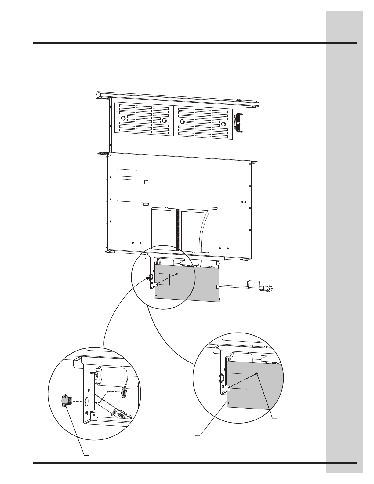
Remove the Duct Transition
Remove the Duct Transition from the Chassis
Housing by removing and discarding the four Phillips
screws as shown and sliding the Duct Transition out
of the tabs.
Tab
(2) Phillips
Head Screws
Duct Transition
(2) Phillips
Head Screws
Converting the Blower
7
Remove Control Box Cover
Remove the cover to the Control Box by removing
the Phillips screw as shown and sliding the cover
down.
Remove Romex Cable Clamp
Remove the Romex cable clamp from the right side
of the control box.
Romex Clamp
Phillips
Screw
Control Box
Cover
8
Converting the Blower
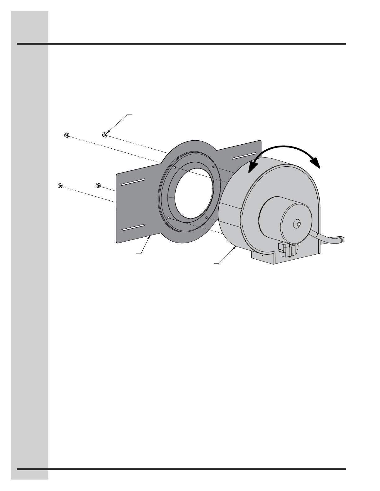
Rotate the Blower (if needed)
Remove the four 1/4 nylon insert nuts from the blower
studs and detach the slide plate. Rotate the blower
90 degrees left or right as required for ducting and
reattach to the slide plate. Re-install the four 1/4”
nylon insert nuts on the blower studs.
1/4” Nylon Insert Nut
e
f
L
t
e
o
t
a
t
o
R
r
R
i
g
h
t
Slide Plate
Blower
Converting the Blower
9
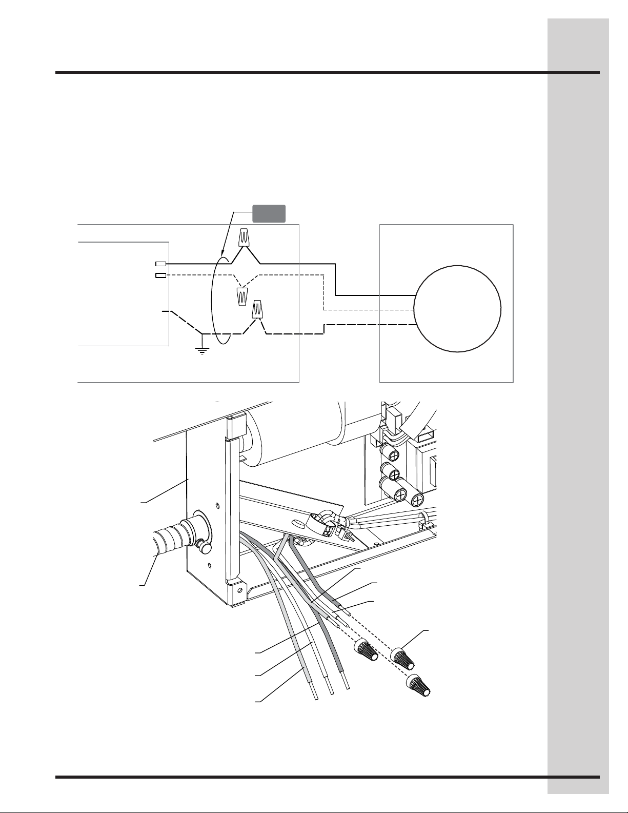
Make Electrical Connection from
Blower to Control Box
Connect the Blower electrical conduit to the Control
Box using the conduit tting attached to the cable.
Use pliers to tighten the locknut. DO NOT use a
screwdriver or other instrument to strike and tighten
the locknut on the conduit tting.
DOWNDRAFT
PIGTAIL
Connect the Blower wiring to the Control Board,
following the wiring diagram.
CONTROL BOX INTERNAL BLOWER
P8
P11
BLK
WHT
GRN
CONTROL BOARD
CONTROL
GND
HOUSING
Motor
120 VAC
Control Box
Blower
Conduit
Ground (Green)
Line (Black)
Neutral (White)
Wire Nuts (3)
Line
Neutral
Ground
Internal Blower
Wiring Connection
10
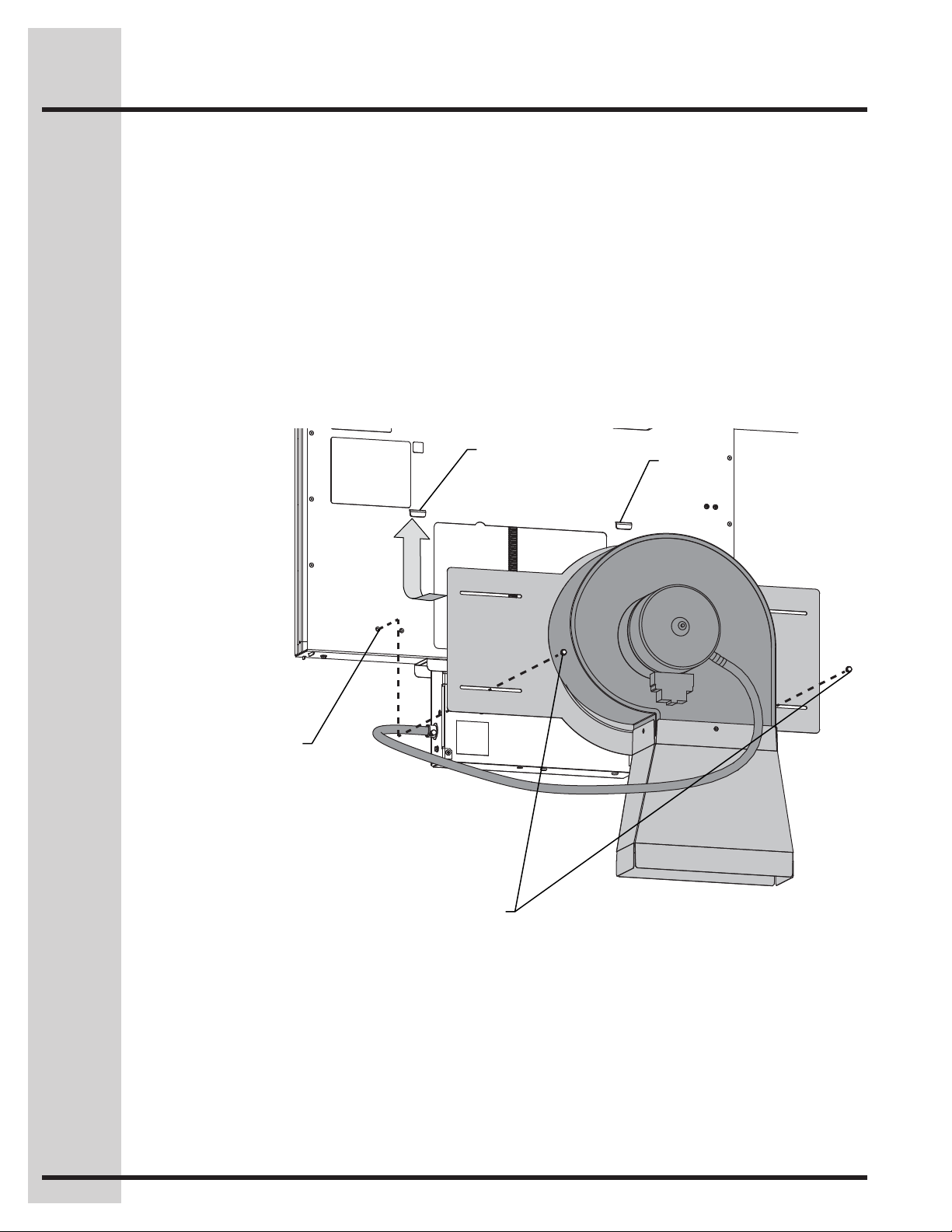
Converting the Blower
Replace Control Box Cover and
Attach Blower to the Chassis
Replace the cover on the Control Box and fasten with
the Phillips screw previously removed.
Attach the Blower and Slide Plate assembly to the
Chassis Housing by first sliding the Slide Plate
underneath the tabs and then fastening two ¼” hex
head screws in the outermost holes in the bottom slot
of the Slide Plate.
Refer to the Telescopic Downdraft System Installation
Instructions for further instructions on verifying the
proper operation.
Use Outer
Screw Holes
Tab
Tab
1/4” Hex Head Screws
 Loading...