

Page 1
EHG645BE EHG635BE EHG645SE
EHG755SE EHG955SE EHG955BE
EHG953BE
User manualCooking
Page 2

2 electrolux.com.au 3
IMPORTANT INSTRUCTIONS
CONGRATULATIONS
Dear customer,
Thank you for purchasing an Electrolux cooktop.
You’ve chosen a product that brings with it decades
of professional experience and innovation. Ingenious
and stylish, it has been designed with you in mind.
So whenever you use it, you can be safe in the
knowledge that you’ll get great results every time.
Welcome to Electrolux.
The symbols you will see in this booklet have
these meanings:
WARNING
This symbol indicates information concerning your
personal safety.
CAUTION
This symbol indicates information on how to avoid
damaging the cooker or cabinet.
IMPORTANT
This symbol indicates tips and information about
use of the cooker.
ENVIRONMENT
This symbol indicates tips and information about
economical and ecological use of the cooker.
NOTE: Model codes shown in this manual are the generic
code. Your product will also include a two letter suffix
which denotes colour and series level.
CONDITIONS OF USE
This appliance is intended to be used in household and
similar applications such as:
• Staff kitchen areas in shops, offices and other
working environments
• Farm houses
• By clients in hotels, motels and other residential
type environments
• Bed and breakfast type environments
• Catering and similar non-retail applications
Record model and serial number here:
Model number: ____________________________________
Serial number: _____________________________________
CONTENTS
Important Instructions _________________________ 3
Part names __________________________________ 4
Before first use _______________________________ 8
Using your cooktop ___________________________ 9
Burners _____________________________________ 9
Cleaning and care ____________________________ 10
Troubleshooting ______________________________ 13
Technical data _______________________________ 14
Installation instructions ________________________ 16
Installation procedure _________________________ 19
Gas connection _____________________________ 25
LP conversion _______________________________ 27
Electrical connection __________________________ 28
Testing appliance operation ____________________ 29
Warranty ____________________________________ 31
Important Information that may impact your
Manufacturer’s Warranty
Adherence to the directions for use in this manual
is extremely important for health and safety. Failure
to strictly adhere to the requirements in this manual
may result in personal injury, property damage and
affect your ability to make a claim under the Electrolux
manufacturer’s warranty provided with your product.
Products must be used, installed and operated in
accordance with this manual. You may not be able to
claim on the Electrolux manufacturer’s warranty in the
event that your product fault is due to failure to adhere
to this manual.
BEFORE USING YOUR APPLIANCE
Before you use the appliance, we recommend that
you read through the relevant sections of this manual,
which provides the description of your appliance and
its functions.
To avoid the risks that are always present when you use
an appliance, it is important that the appliance is installed
correctly and that you read the safety instructions carefully
to avoid misuse and hazards.
We recommend that you keep this instruction booklet for
future reference and pass it on to any future owners.
This appliance complies with the requirements of
Australian Standard AS 5263.
IMPORTANT
Check for any damage or marks. If you find the
appliance is damaged or marked, you must report
it within 7 days if you wish to claim for damage/
marks under the manufacturer’s warranty. This
does not affect your statutory rights.
Information on disposal for users
ENVIRONMENT
• Most of the packaging materials are
recyclable. Please dispose of these materials
through your local recycling depot or by
placing them in appropriate collection
containers.
• If you wish to discard this product, please
contact your local authorities and ask for the
correct method of disposal.
Read the following carefully to avoid damage or injury.
WARNING
• Do not allow pots to boil dry, as damage to both pan
and cooktop may result.
• Do not operate the cooktop for an extended period
of time without a pot or pan on the burner.
• Do not allow large cookware to overhang the
cooktop onto adjacent benchtop. This will cause
scorching to the benchtop surface.
• Do not allow cooking pots or pans to intrude into the
area which is close to the controls.
• Ensure burner bodies and trivets are properly located
(see Figure 1).
• This cooktop should not be used with any lid or
covering on top of the cooktop. Combustible
materials must not be stored within 650mm above
the cooktop.
CAUTION
Read the following carefully to avoid an electric
shock or fire.
It is important to use your cooktop safely. Check these
safety points before using your cooktop.
• This appliance is not intended for use by persons
(including children) with reduced physical, sensory
or mental capabilities, or lack of experience and
knowledge, unless they have been given supervision
or instruction concerning use of the appliance by a
person responsible for their safety.
• Children should be supervised to ensure they do not
play with this appliance.
• During use, this appliance becomes hot. Care should
be taken to avoid touching hot surfaces. To avoid
burns, young children should be kept away.
• DO NOT USE THIS APPLIANCE AS A SPACE
HEAT ER.
• Keep vents clear of obstructions.
• In order to avoid a fire, this appliance must be
kept clean.
• DO NOT SPRAY AEROSOLS IN THE VICINITY OF
THIS APPLIANCE WHILE IT IS IN OPERATION
• DO NOT USE OR STORE FLAMMABLE MATERIALS
IN THE APPLIANCE STORAGE DRAWER OR NEAR
THIS APPLIANCE
• Do not remove the trivet and enclose the burner with
a wok stand as this will concentrate and deflect heat
onto the burner.
• Do not use large pots or heavy weights which can
bend the trivet or deflect flame onto the burner.
• Do not place anything, e.g. asbestos mat between
pan and trivet as serious damage to the cooktop
may occur.
• For maximum stability, ensure pots and pans are
centrally located on the trivets.
• Handles should be turned away from the front of the
bench to avoid accidents.
• DO NOT MODIFY THIS APPLIANCE.
• Only models fitted with flame safeguard can be used
in marine craft, caravans or mobile homes.
Page 3
4 electrolux.com.au 5
PART NAMES
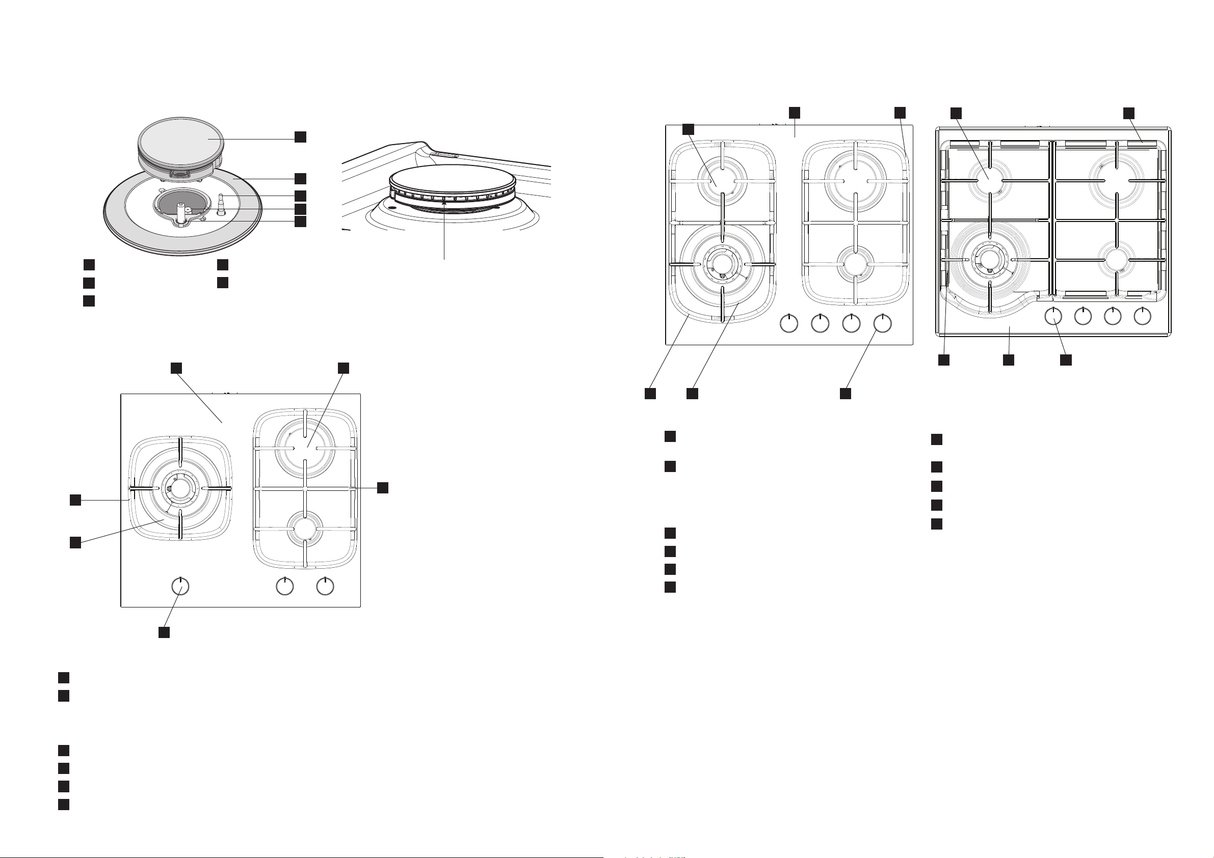
Description of the burner
Figure 1a
1
Burner
2
Skirt
3
Flame safeguard
sensor
Figure 2a
Figure 2c
1 2
4
Injector
5
Ignition spark
1
2
3
4
5
Figure 1b
Figure 2b
62
1
Burner flame ports
plug
2
1
5 4 3
5
4
3
EHG635BE
1
Burners – this unit has a small, large and dual wok burner
2
Ceramic Glass hob – the glass hob is resistant to heat, cold
and rapid temperature changes, but is vulnerable to impact.
A pepper mill falling on the hob could crack it. Never stand
or put heavy loads on the hob, or use as a storage space
3
Control knob
4
Enamelled burner skirts
5
Removable cast iron trivet (left)
6
Removable cast iron trivet (right)
345
EHG645BE
1
Burners – this unit has a small, medium, large and
dual wok bu rner
2
Ceramic Glass hob – the glass hob is resistant to
6
heat, cold and rapid temperature changes, but is
vulnerable to impact. A pepper mill falling on the hob
could crack it. Never stand or put heavy loads on
the hob, or use as a storage space
3
Control knob
4
Enamelled burner skirts
5
Removable cast iron trivet (left)
6
Removable cast iron trivet (right)
EHG645SE
1
Burners – this unit has a small, medium, large and
dual wok burner
2
Removable cast iron trivet (right)
3
Control knob
4
Stainless Steel hob
5
Removable cast iron trivet (left)
Page 4
6 electrolux.com.au 7
PART NAMES (CONTINUED)
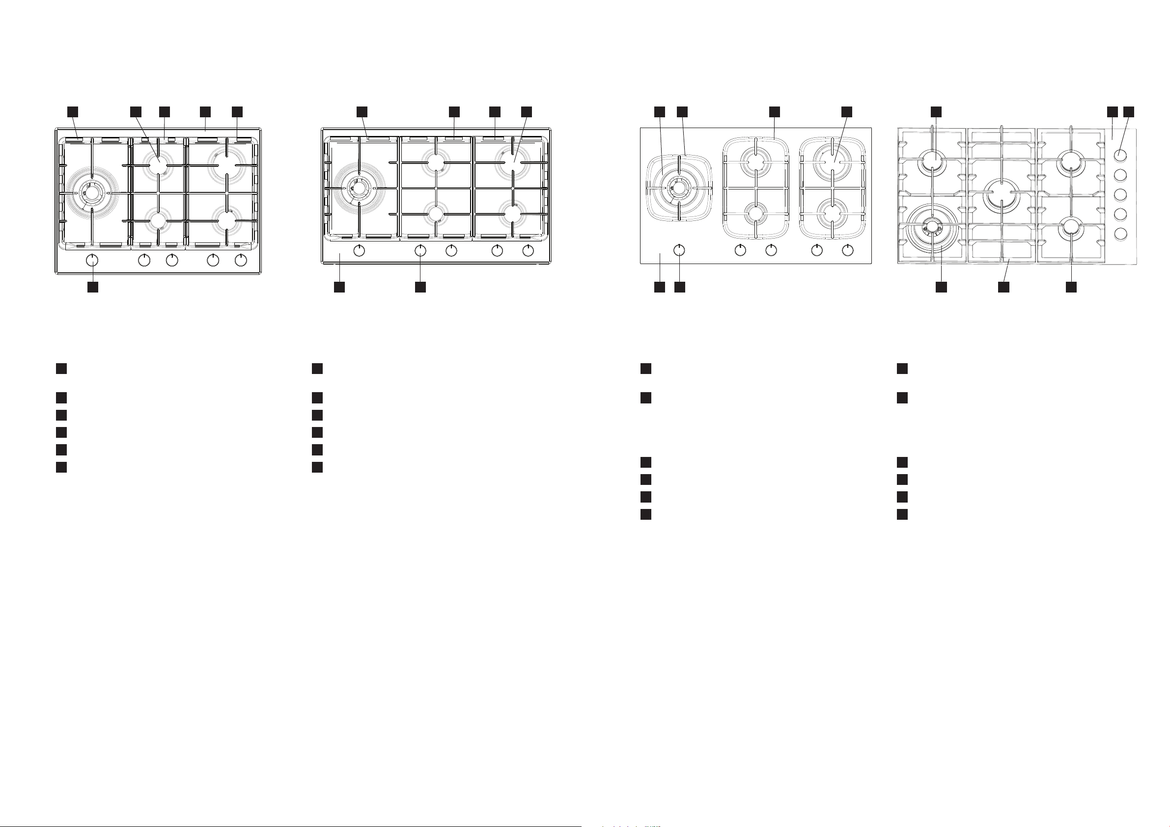
Figure 2d
5 5 6 2
3 3 3 42 2 5 6
2 614 4 54 16 1 1
EHG755SE
1
Burners – this unit has a small, medium (2 per), large
and dual wok burner
2
Stainless Steel hob
3
Control knob
4
Removable cast iron trivet (left)
5
Removable cast iron trivet (mid)
6
Removable cast iron trivet (right)
Figure 2e
EHG955SE
1
Burners – this unit has a small, medium (2 per), large
and dual wok burner
2
Stainless Steel hob
3
Control knob
4
Removable cast iron trivet (left)
5
Removable cast iron trivet (mid)
6
Removable cast iron trivet (right)
Figure 2f
EHG955BE
1
Burners – this unit has a small, medium (2 per), large
and dual wok burner
2
Ceramic Glass hob – the glass hob is resistant to
heat, cold and rapid temperature changes, but is
vulnerable to impact. A pepper mill falling on the hob
could crack it. Never stand or put heavy loads on the
hob, or use as a storage space
3
Control knob
4
Enamelled burner skirts
5
Removable cast iron trivet (left)
6
Removable cast iron trivet (mid and right)
Figure 2g
EHG953BE
1
Burners – this unit has a small, medium (2 per), large
and dual wok burner
2
Ceramic Glass hob – the glass hob is resistant to
heat, cold and rapid temperature changes, but is
vulnerable to impact. A pepper mill falling on the hob
could crack it. Never stand or put heavy loads on the
hob, or use as a storage space
3
Control knob
4
Enamelled burner skirts
5
Removable cast iron trivet (left)
6
Removable cast iron trivet (mid and right)
3
Page 5
8 electrolux.com.au 9
BURNERSUSING YOUR COOKTOPBEFORE FIRST USE
INSTALLATION
• An authorised person must install this appliance and
MUST provide a Certificate of Compliance.
This certificate should be retained along with
purchase information.
• Before using the appliance, ensure that all packing
materials are removed from the appliance.
• In order to avoid any potential hazard, the installation
instructions in this booklet, and any labels on the
appliance must be followed.
• Ensure that all specified vents, openings and air
spaces are not blocked.
• Where the appliance is built into a benchtop, the
benchtop material must be capable of withstanding
85°C.
• Ensure that the duplicate rating label (in the
instruction pack) is attached to a readily accessible
adjacent surface, so that the cooktop can be easily
identified in the case of a service call.
SERVICING
• Servicing MUST only be carried out by authorised
personnel.
• To maintain safe operation, it is recommended that
the product be inspected every five years by an
authorised service person.
• If the supply cord is damaged, it must be replaced
by the manufacturer, its service agent or similarly
qualified persons in order to avoid a hazard.
CLEANING
• Always ensure the appliance is turned off before
cleaning.
• This appliance contains aluminium fittings.
Do not use caustic based cleaners.
• Do not use steam cleaners as this may cause
moisture build up on electrical components.
• Always clean the appliance immediately after
any food spillage.
• Do not place any components in a dishwasher.
• Refer to page 10 for care and cleaning instructions for
stainless/ ceramic hob panel.
CAUTION
• Do not place burners or trivets in a dishwasher.
CONTROLS
Each burner is controlled by a control knob. The markings
on the control panel indicate which burner the knob
controls, and the setting for that burner (see Figure 4).
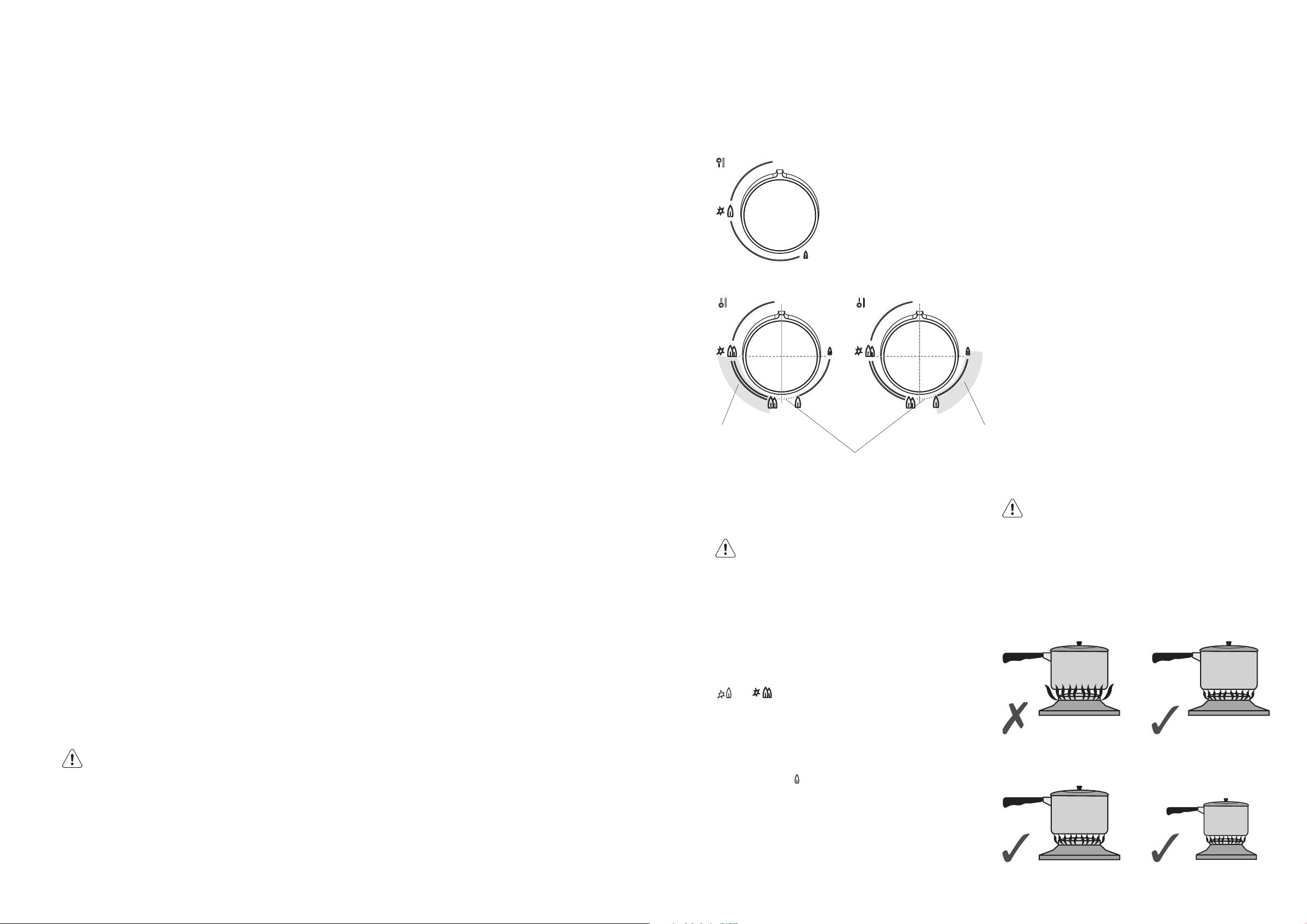
LIGHTING BURNERS
Electronic ignition: These cooktops are fitted with
mains powered ignition. When the appliance has been
connected and the power is on, depressing any knob will
release sparks to all burners.
Figure 4
Standard burner
Dual wok burner
Both rings of wok
burner operate in
this range of knob
rotation
Note that the dotted line section of
the graphics is the transition between
operating zones. It is recommended
not to leave the knob in this position
Only the inner
ring of the wok
burner operates
in this range of
knob rotation
NOTE! Gas controls turn anticlockwise from ‘OFF’ and
have limited movement.
CAUTION
• Keep hands clear of burners when lighting.
• If burner does not light within 5 seconds, turn knob
to ‘OFF’ position, allow gas to disperse, then try
lighting again.
• Burners MUST be operated between ‘HIGH’ and
‘LOW’ settings only. It is recommended not to operate
the dual wok burner in the area with dotted graphics.
To light a burner, the knob must be turned to the
or ‘HIGH’ position, then pushed down as far as
possible for approximately 5 seconds. If the flame goes out
when the knob is released simply depress the knob again,
this time holding it down with slightly more force for the
same length of time.
The height of the flame can be varied by turning the control
knob toward the
‘LOW’ position.
Note! When the wok burner is turned to low only the small
inner ring stays lit. This is a normal function of
the dual wok burner to provide a very low power
flame option.
Choice of burner
For your convenience there is a choice of burners:
• A small burner for special low heat and
slow cooking.
• A medium burner for normal cooking and simmering
(one on the four burner models and two on the five
burner models).
• A large burner for fast heating and large pots
and pans.
• A wok burner for very fast heating using a wok or
large pot or pan. This wok burner is also a “dual”
burner and therefore results in a small low powered
flame when the burner is turned down. This is
achieved by only supplying gas to the inner ring of the
wok burner.
To conserve gas place the pan centrally over the burner
and adjust the flame so that it does not extend past the
edge of the pan (Figure 5). Do not boil food too rapidly.
A vigorous boil will not cook food any faster, and will
waste energy.
Pots and pans
All common pots and pans; aluminium, stainless steel,
cast iron, ceramic, etc., may be used on your new gas
cooktop. Ensure that the pots or pans are steady and have
flat bases to avoid dangerous spill-over of hot liquids and
wasted energy.
CAUTION
Never use asbestos mats, wire mats or grids,
or aluminium foil as it can lead to overheating,
cracked enamel or broken glass. The warranty will
be void if these items are used and cause a failure.
Woks should only be used on the wok burner and
wok support trivet (refer to Figure 3 on page 7).
Figure 5
Incorrect – flame too high
and will cause gas waste
and possible handle damage.
Correct flame height.
Gas saved.
In the absence of electrical power, carry out the ignition
directly to the burner with a hand held ignition source.
For a large burner,
use a large utensil.
For a small burner,
use a small utensil.
Page 6
10 electrolux.com.au 11
CLEANING AND CARE
CAUTION
Ensure the appliance is off and cool before cleaning.
Enamel (on burner skirts and trivets)
Persistent stains may require rubbing with a nylon scourer or creamed powder cleansers. Household enamel cleaners are
available, follow the manufacturer’s instructions in their use. Harsh abrasive cleaners, powder cleaners, steel wool
or wax polishes should not be used.
Stainless steel (Models with Stainless Steel hob)
Simply wipe with a soft cloth using warm water and a mild detergent and rinse with clean water. Where stainless steel has
become extremely dirty or discoloured, use a stainless steel cleaner – but be sure to follow the brushing lines.
CAUTION
If the ceramic glass surface is cracked, switch off the appliance immediately to avoid the possibility of electric shock.
Trivets and burners
These can all be lifted off and removed for separate cleaning.
NOTE! When refitting the burners, ensure that they are correctly seated.
Ensure burners are thoroughly dried after cleaning or spillage. When cleaning the burners, ensure that all the flame ports
are free of any blockage (refer to Figure 1b on page 4). If necessary, use a toothpick or brush to clear ports. The outer
surface of the burner caps have a polished finish and extra care needs to be taken to avoid scratching this surface during
cleaning. In instances of heavy soiling, it may be necessary to apply a non-abrasive cleaning compound and rub with a
cloth until the soiling is removed and then finish with a soft, dry cloth.
NOTE! DO NOT place trivets or burners in the dishwasher.
Ceramic Cooktop Cleaning
CUSTOMER ADVICE
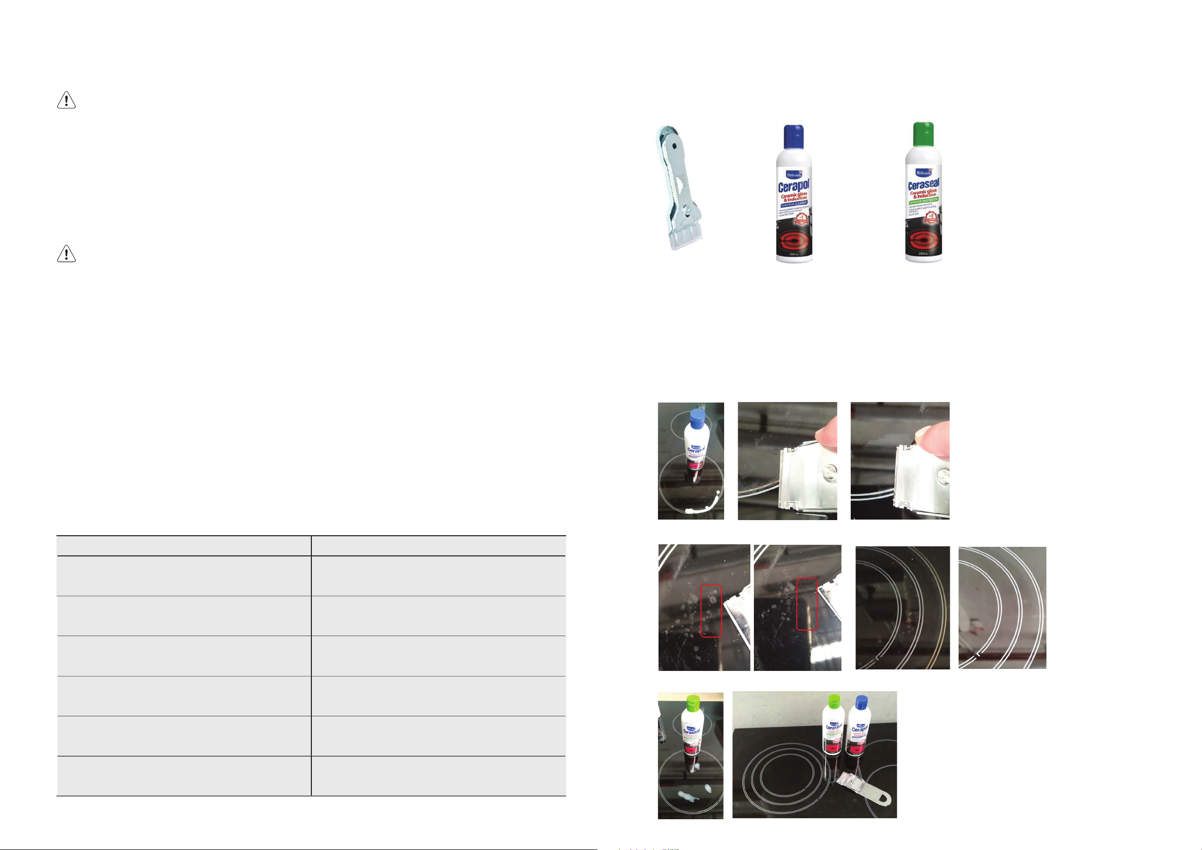
Sometimes SURFACE stains appear to be a “bubble” mark under the ceramic glass.
These can be cleaned off with a razor blade scraper and ceramic cleaner.
Keeping the ceramic cooktop clean and protected will keep it in good condition and help avoid breakage.
Ceramic
Scraper
0383001001
Cerapol
Cleaner
ACC019
Ceraseal
Protector
ACC018
Available at the following web shops.
https://shop.electrolux.com.au
If the deposit is minimal, simply wipe off with a dry cloth.
If the deposit is more stubborn, clean off with a moist soapy sponge then rinse off.
If the deposit still does not clean off easily, use a non-abrasive nylon scratch pad and special purpose ceramic glass
cleaning agent such as Cerapol cleaner (ACC019 - Available from our web shop).
If the deposits are still burnt on and above methods did not work, use a specially designed ceramic glass scraper
(0383001001 - Available from our web shop).
After having successful cleaned the cooktop, apply a ceramic glass conditioner Ceraseal protector (ACC018 Available from our web shop). The conditioner will leave a protective coating that will help prevent future stains from
becoming baked on. Marks which appear to be bubbles under the ceramic will also clean off. Use Ceraseal (ACC018)
to help protect the ceramic and allow for easier cleaning. Polish on with a dry clean cloth.
Ignition spark plug and flame safeguard sensor
GENTLY clean the ignition spark plug and flame safeguard sensor with a damp cloth to avoid lighting difficulties.
Ensure that they are dry before use.
Injector
Ensure the injector remains free of any foreign material. When cleaning the burner spill bowl, first put tape over the injector
hole before wipe out the spill bowl to avoid to block the injector hole, then remove the tape after cleaning.
If necessary, use a thin piece of wire to clear the orifice.
Do’s Don’ts
Use pots with a flat base.
Clean when cold unless sugar spills which should be removed
with a ceramic scraper.
Clean after every use with a sponge and soapy water then dry.
Use a non-scratch scourer (usually blue in colour) if required.
Do not slide pots across the glass as this can results in
scratches to the surface
Do not clean when hot as it is dangerous and cleaning
products can burn and stain.
Do not leave food residues or water on the ceramic as the
contamination can damage the ceramic and screening printed
graphics
Do not use steel wool or scourer pads that are not specified as
non-scratch (usually green in colour). Heavy duty scourers are
too abrasive
Marks which appear to be bubbles under the ceramic will also clean off.
Use Ceraseal (ACC018) to help protect the ceramic and allow for easier cleaning. Polish on with a dry clean cloth.
Difficult stains should be removed with a ceramic scraper and
cleaning cream specific for ceramic glass cooktops. Cerapol
At least once per week use ceramic sealer cream. Ceraseal
Do not use general abrasive cleaners as these can cause
micro-scratches, dulling the glass surface and increasing the
likelihood of contamination embedding into the glass
Do not use the ceramic top as a cutting board or work bench
as this will cause scratches.
Page 7
12 electrolux.com.au 13
CLEANING AND CARE
Stainless Steel Cooktop Cleaning
NOTE: Ensure any oil is cleaned off the hob before use, otherwise it may cause the hob to turn a
yellowish colour. All grades of stainless steel may stain, discolour or attain an adhering layer of grime in
normal operation. To achieve maximum surface appearance, stainless steel must be kept clean.
Do’s Don’ts
Clean in the direction of stainless steel brushing lines.
Wash with warm soapy water. Do not use caustic cleaners.
For stains use a specific stainless-steel cleaner ACC031.
Always clean the stainless steel after food spillage. Some foods may discolour the stainless steel.
Use the correct sized pot as described in the owner manual.
NOTE: Do not use stainless steel cleaners on oven doors or control panels with finger print proof
coating. Refer to owner manual for specific models.
Do not clean against the stainless steel brushing lines as
this will cause scratching.
Do not use abrasive cleaners, scourers or steel wool as this will
cause scratching.
Do not oversized pots as they can reflect heat onto the stainless
steel causing discolouration.
INSTALLATION INSTRUCTIONS
This appliance must be installed by an authorised person
and in compliance with:
1. AS/NZS 5601.1 Gas Installations Part 1: General
Installations, and AS/NZS 5601.2 Gas Installations
Part 2: LP Gas installations in caravans and boats for
non-propulsive purposes, or the relevant installation
code for gas appliances in your country.
2. The local gas fitting regulations, municipal building
codes, electrical wiring regulations and any other
relevant statutory regulations.
3. The particular instructions as given below.
4. A certificate of compliance MUST be given
to the customer after the application is
successfully installed.
CAUTION
Cooktops are supplied set up for natural gas (NG).
To use on LPG, the injectors must be changed
using the conversion kit supplied. Refer LP
conversion on page 24-25.
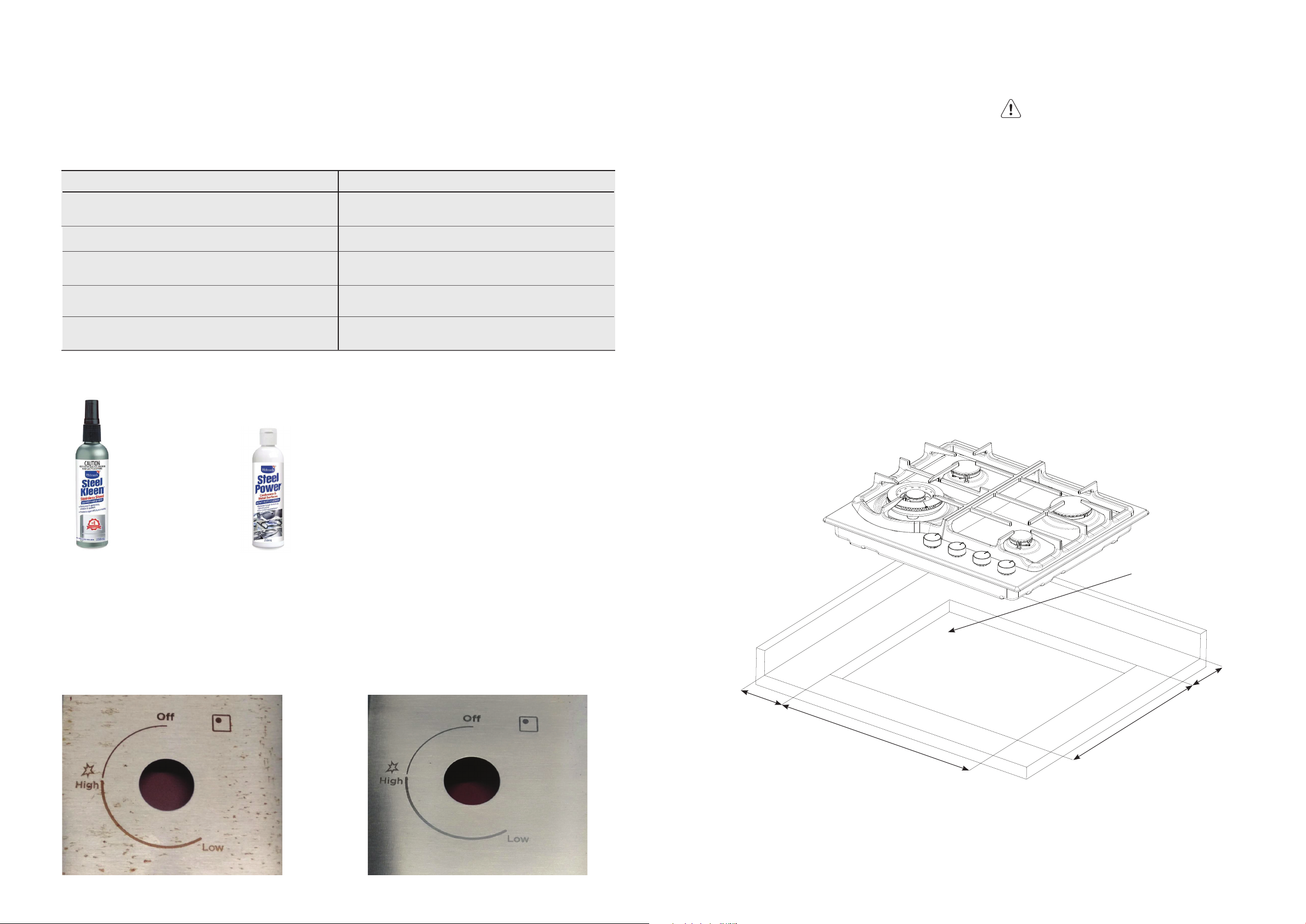
Steel Kleen
ACC032
Steel Power
ACC031
Available at the following web shops or distributors.
https://shop.electrolux.com.au/
Remove deposits with a soft cloth and warm soapy water then wipe with a dry soft cloth. If there are signs of yellowing
or stubborn stains, use a suitable stainless steel cleaner Steel Kleen (ACC032 - Available from our web shop), apply
with a soft cloth and clean in the direction of the stainless steel grain only.
After the cooktop is clean, apply stainless steel protectant Steel Power (ACC031 - Available from our web shop) which
will leave a protective coating to help prevent future stains from occurring.
Before After
Figure 6a – EHG645SE & EHG645BE & EHG635BE
gas supply connection location
146 min*
148 min*
490
560
* to combustible surface (dimension is not relevant
if the adjacent surface is non-combustible).
Page 8

14 electrolux.com.au 15
TECHNICAL DATA
We reserve the right to alter these specifications.
This appliance conforms to AS 5263.
Table 2
features EHG635BE EHG645BE EHG645SE EHG755SE EHG955SE EHG955BE EHG953BE
Cooking zones 3 4 4 5 5 5 5
Wok Yes, dual Yes, dual Yes, dual Yes, dual Yes, dual Yes, dual Yes, dual
Ignition 230-240V 230-240V 230-240V 230-240V 230-240V 230-240V 230-240V
Trivet Cast Cast Cast Cast Cast Cast Cast
Hob material Ceramic glass Ceramic glass Stainless steel Stainless steel Stainless steel Ceramic glass Ceramic glass
Features Ignition through knob Ignition through knob Ignition through knob Ignition through knob Ignition through knob Ignition through knob Ignition through knob
Flame safeguard Yes Yes Yes Yes Yes Yes Yes
Colours Black Black Stainless steel Stainless steel Stainless steel Black Black
Gas types
cooktop dimensions (mm)
Width 595 595 595 745 895 895 861
Depth 530 530 530 530 530 530 520
Height
(from top of pan support to bench)
Height
(from bench to bottom)
cut out dimensions (mm)
Width 560 560 560 710 860 860 830
Depth 490 490 490 490 490 490 470
energy rating (NG) – MJ/h
Small burner 5 .1 5.1 5.1 5 .1 5.1 5.1 5 .1
Medium burner NA 9 9 2X9 2X9 2X9 2X9
NG, (LP conversion kit
supplied)
66 60 60 60 60 66 55
55 55 55 55 55 55 55
NG, (LP conversion kit
supplied)
NG, (LP conversion kit
supplied)
NG, (LP conversion kit
supplied)
NG, (LP conversion kit
supplied)
NG, (LP conversion kit
supplied)
NG, (LP conversion kit
supplied)
Large burner 12.1 12.1 12.1 12.1 12.1 12.1 12 .1
Wok burner 24 17 17 24 24 24 17
Total MJ/h 41. 2 43.2 43.2 59.2 59.2 59.2 52.2
Page 9
16 electrolux.com.au 17
INSTALLATION INSTRUCTIONS (CONTINUED)
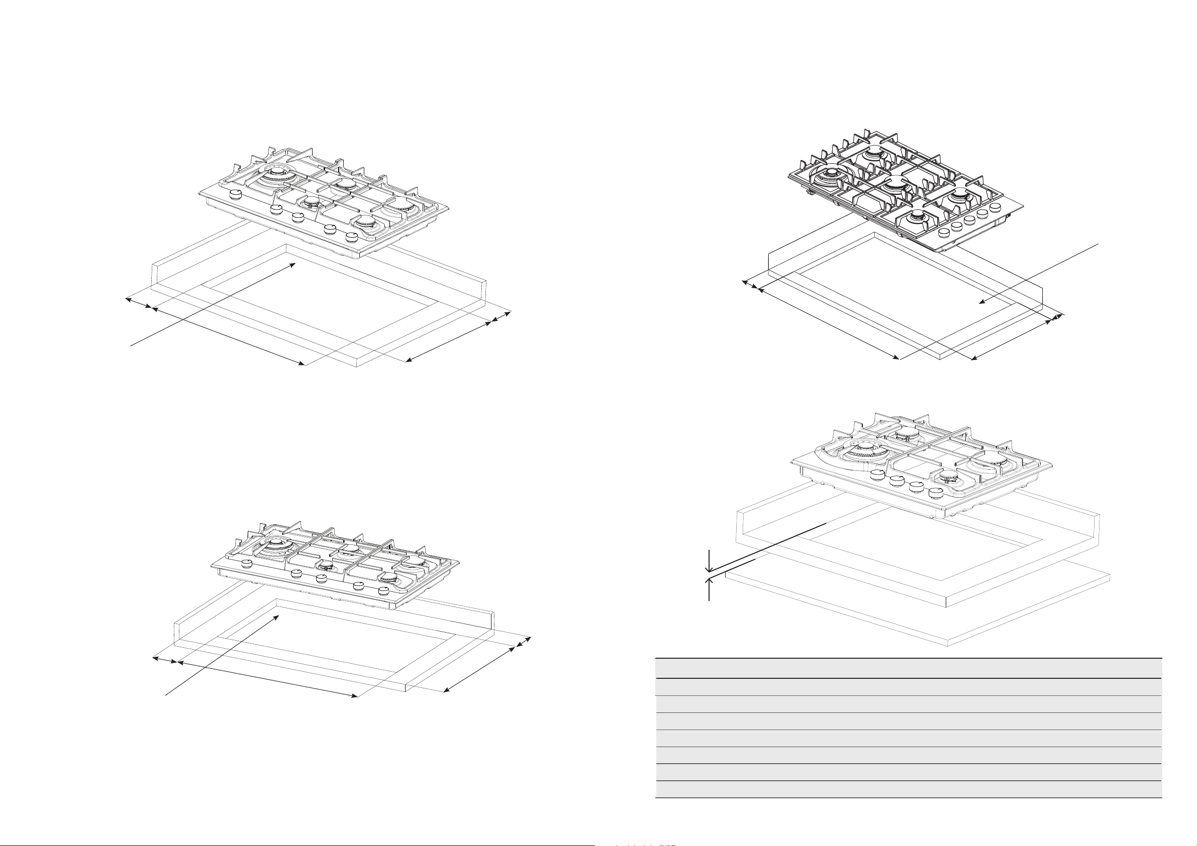
Figure 6d – EHG953BE
Figure 6b – EHG755SE
gas supply connection
location
151 min*
710
gas supply connection
location
Figure 6c – EHG955SE & EHG955BE
490
146 min*
161 min*
Clearance from bench to bottom
Clearance
830
126
470
136 min*
gas supply connection
location
* to combustible surface (dimension is not relevant
if the adjacent surface is non-combustible).
860
490
146 min*
Model Non-Combustible surface (mm) Combustible surface (mm)
EHG635BE 55 75
EHG645BE 55 75
EHG645SE 55 75
EHG755SE 55 75
EHG955SE 55 75
EHG955BE 55 75
EHG953BE 55 75
Page 10
18 electrolux.com.au 19
INSTALLATION PROCEDURE
1. The bench cutout should be made as per cutout
dimensions in Table 2 and Figure 6.
2. Adjacent walls, cupboards and protection for
combustible materials: Ensure that the appliance
is installed in accordance with AS/NZS 5601.1,
or AS/NZS 5601.2 with regard to clearances
to combustible surfaces and materials, and
clearances to rangehoods and exhaust fans.
To ensure clearances of 200mm from burners
to vertical combustible surfaces observe the
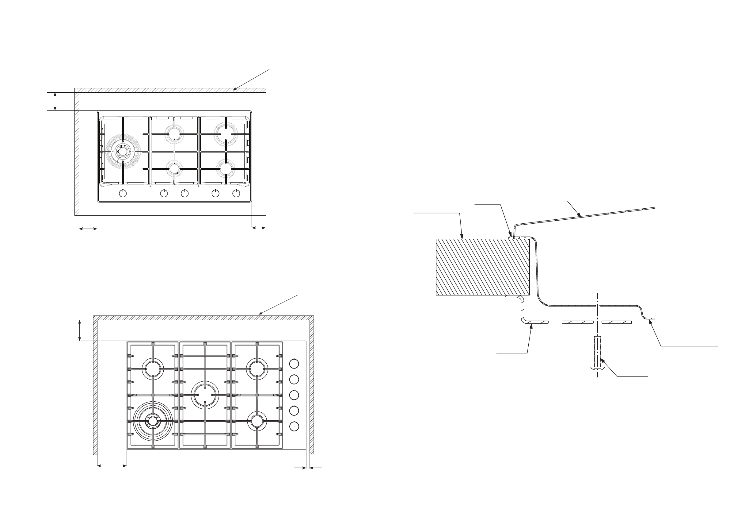
minimum distance requirements shown in Figure 7.
Clearances to combustible surfaces may be
reducedif combustible surfaces are protected
in accordance with AS/NZS 5601.1, or AS/NZS
5601. 2.
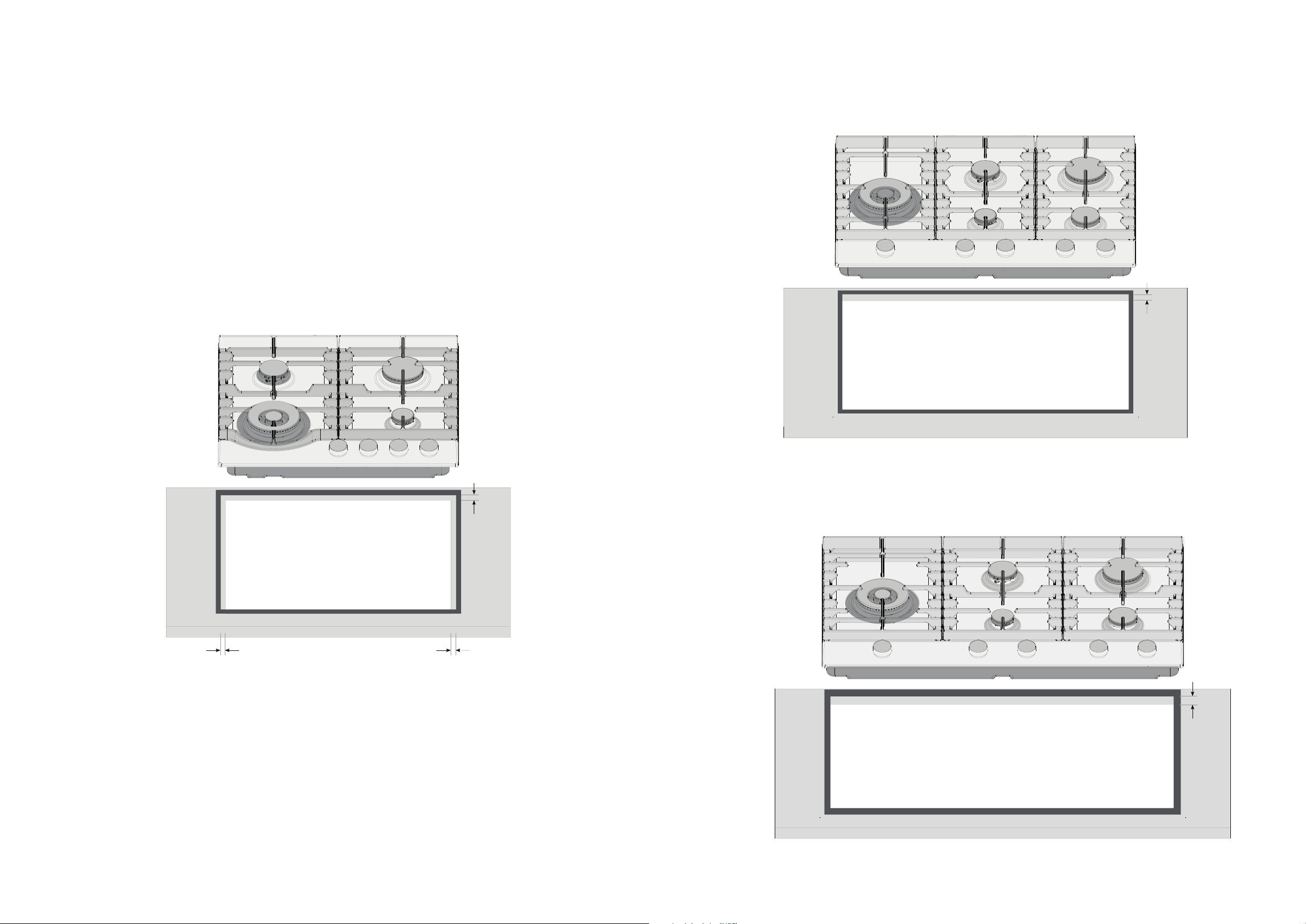
3. For Ceramic Glass models a FOAM SEAL has
been provided and is to be applied along the
perimeter of the hob.
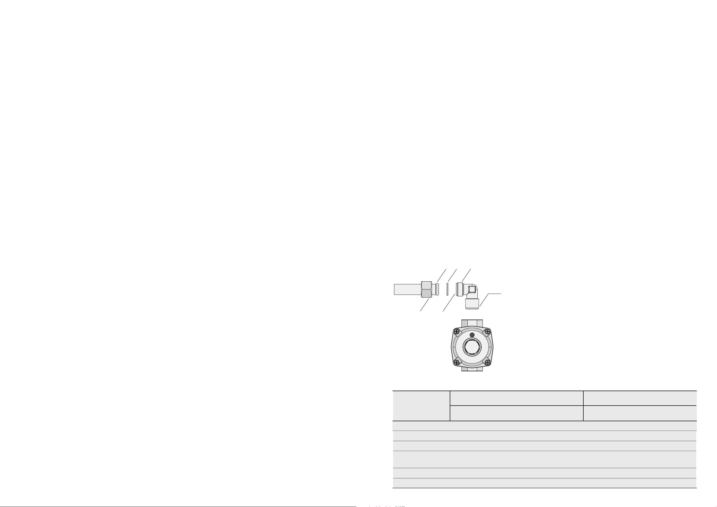
4. For Stainless Steel models MASTIC TAPE has
been provided and is to be placed around the
bench cutout as specified in Figure 8. Take care to
ensure that the seals meet without overlapping.
5. Fit the pull down clamps supplied to ensure that
the cooktop cannot move after installation.
6. On Stainless Steel models remove any excess seal
visible after installation.
WARNING!
Failure to fix the cooktop to the bench could result in
loosening of the gas connection through movement of the
cooktop and a gas leak may result.
Four clamps and screws are supplied with 3/4-burner
models and six clamps and screws are supplied with
5-burner models. Fit the clamps as shown in Figure 8.
When benchtops are less than 33mm in thickness, it may
be necessary to fit a spacer between the benchtop and
each clamp to ensure clamps can be tightened sufficiently.
INSTALLATION PROCEDURE (CONTINUED)
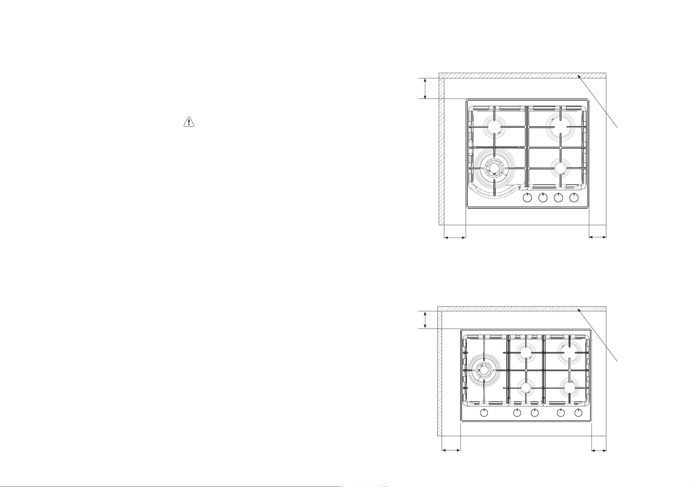
Figure 7a – EHG645SE & EHG645BE & EHG635BE
115
combustible surface
Figure 7b – EHG755SE
115
131
113
combustible surface
134
126
Page 11
20 electrolux.com.au 21
INSTALLATION PROCEDURE (CONTINUED)
Figure 7c – EHG955SE & EHG955BE
combustible surface
115
Figure 8 – Clamp fitment
120 101
Figure 7d – EHG953BE
101
combustible surface
benchtop
seal
hob
burner box
clamp
screw
145
no minimum
distance
Page 12
22 electrolux.com.au 23
INSTALLATION PROCEDURE (CONTINUED)
Figure 8b - Mastic seal position for model EHG755SE
25mm
Figure 8a - Mastic seal position for model EHG645SE
12mm
25mm
Figure 8c - Mastic seal position for model EHG955SE
12mm
25mm
Page 13
24 electrolux.com.au 25
GAS CONNECTION
OPERATION ON N.G./S.N.G
This appliance is supplied for use with Natural Gas.
However, it can be converted for use with LPG.
Refer to LP conversion on page 25.
Supply pipe sizing
The total hourly gas consumption for the appliance is
shown on the data label. The required supply pressure (i.e.
at inlet to appliance regulator) for each gas type is shown
on the data label, and given in Table 3 (page 24). Use this
information in conjunction with the length of run, number
of elbows, tees and bends, the available service pressure
and the supply requirements of other installed appliances
to determine a suitable pipe size. For assistance in this
matter refer to the appropriate section of AS/NZS 5601.1
or AS/NZS 5601.2.
An AGA certified class B or D flexible connection may
be used to connect the cooktop in accordance with
AS/NZS 5601.1, in particular section 5.9 and clause
6.10.1.8, or AS/NZS 5601.2, in particular section 2.11.
Where a hose assembly is used and the cooktop is in the
installed position, the hose assembly shall be suitable for
connection to a fixed consumer piping outlet located at
a point 800 – 850mm above the floor and in the region
outside the width of the appliance to a distance of 250mm.
The point of connection to consumer piping must be
accessible with appliance installed.
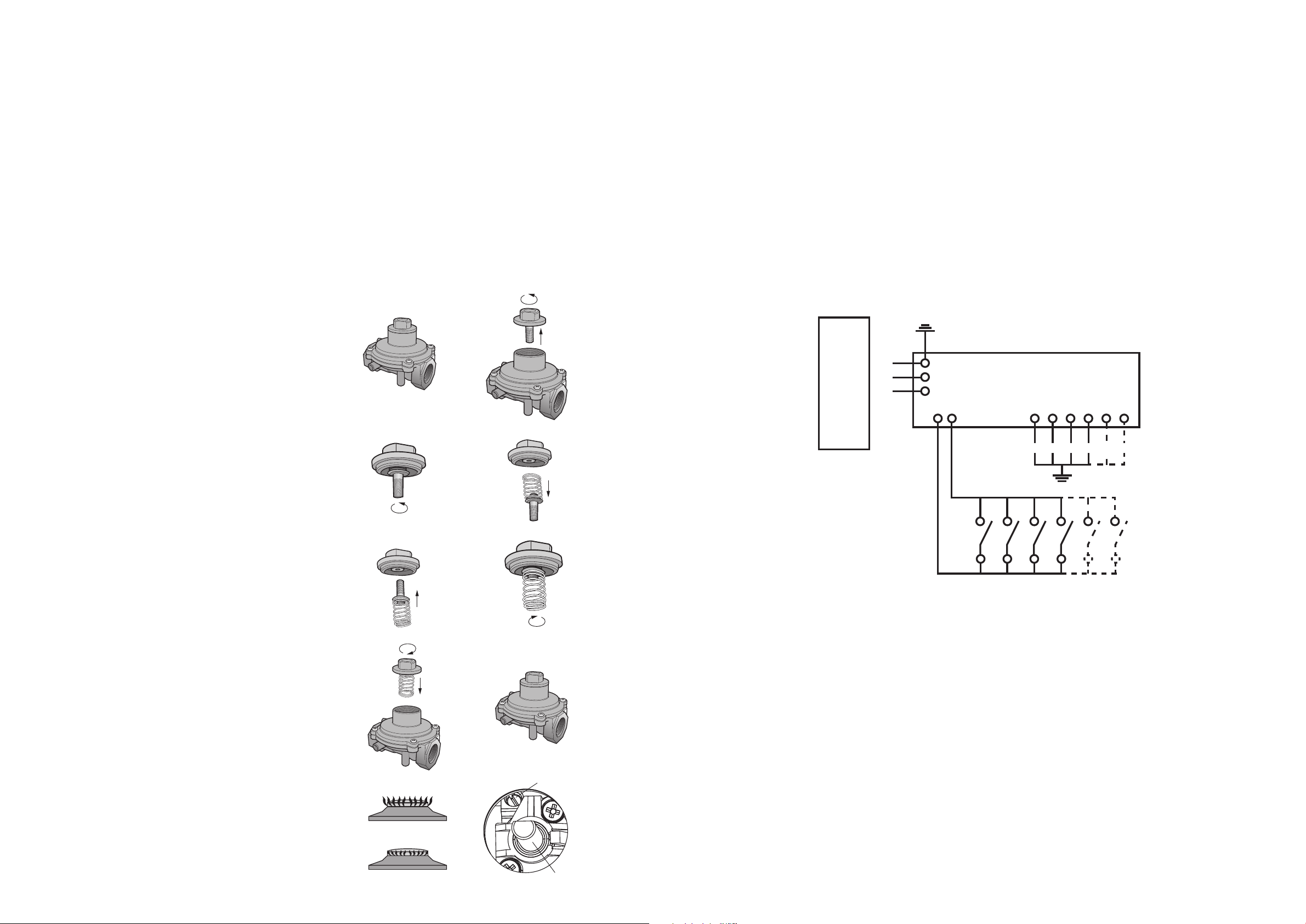
ELBOW POSITIONING
It is possible to reposition the elbow if required by
loosening the locking nut and elbow by using two
spanners. Re-tighten the entire assembly after the elbow
has been repositioned. When fitting elbow to appliance,
ensure that the sealing washer is fitted.
Note to Installer: Assembly of elbow to manifold at rear
of unit requires two spanners to secure locking nut and
ensure leak free connection. For this reason the elbow is
best secured onto cooktop manifold before installing unit
into benchtop.
Regulator
An appliance regulator is provided. The regulator must be
positioned so that the pressure test nipple is accessible
when the appliance is installed.
Connect the gas supply to the ½” B.S.P. internal thread
inlet of the regulator. Refer to ‘bench cutout’ (Figure 6) for
connection point position.
Regulators are supplied pre-adjusted and configured by the
component maker for use with Natural Gas.
The appliance installer is not required to make an
adjustment to obtain the correct outlet pressure setting.
An arrow on the base of the regulator indicates the
direction of gas flow when the inlet and outlet of the
regulator is orientated correctly. When the regulator has
been fitted check for leaks from the connections with
soapy water.
GAS CONNECTION (CONTINUED)
Assembly of the regulator
The assembly of the regulator to the cooktop manifold is
achieved via the elbow union and sealing washer supplied,
refer to figure 9.
The ½” parallel thread connects to the manifold, and the
sealing washer is placed between the manifold end and
the flat face on the elbow.
The ½” tapered thread connects to the outlet of
the regulator, and is sealed on the thread using approved
thread sealing tape or approved thread sealing compound.
The inlet of the regulator is a ½” parallel thread and
is connected to consumer piping or hose assembly.
Regulators are supplied pre-adjusted and configured
by the component maker for use with Natural Gas.
The appliance installer is not required to make an
adjustment to obtain the correct outlet pressure setting.
An arrow on the base of the regulator indicates the
direction of gas flow when the inlet and outlet of the
regulator is orientated correctly. When the regulator has
been fitted check for leaks from the connections with
soapy water.
Figure 9
manifold
endform
female nut flat face
sealing
washer
½” parallel
thread
½” tapered thread
seal using approved
sealing tape or
approved thread
sealing compound
outlet
CHECKING THE GAS SUPPLY
1. Check the manometer zero point is correct.
2. Connect the manometer to the cooktop pressure point.
This is located on the regulator.
3. Turn on the gas supply and electricity and try to
ignite the gas.
NOTE! It will take additional time to light the gas for the first
time as air needs to be purged from the pipes.
4. With the appliance operating check the outlet pressure
• when all burners of the appliance are operating
at maximum,
• when the smallest burner of the appliance is
operating at minimum.
Under these conditions the outlet pressure should not
vary from the nominal outlet pressure of 1.00kPa by
more than ±0.20kPa.
If the regulator appears to not be performing satisfactorily,
then check the following points:
1. If the outlet pressure is consistently too low then the inlet
pressure may be too low and adjustment of an upstream
regulator may be needed, or an upstream regulator or
valve with insufficient flow capacity may be present in
the gas supply line. If this is suspected then it may be
necessary to repeat the checks whilst measuring both
the inlet and outlet pressure to determine if the inlet
pressure is in the range
1.13 – 5kPa.
2. Check that the regulator has been fitted to the gas
supply line in the correct orientation, the arrow on the
base of the body indicates the direction of gas flow.
Once these checks have been completed, if the
regulator still fails to perform in a satisfactory manner it should
be replaced.
LPG (nominal test point pressure:
injector size
(mm)
2.60kPa)
gas consumption
Table 3
burner type
regulator
inlet
natural gas (nominal test point pressure: 1.00kPa)
injector size
(mm)
gas consumption (MJ/h)
Small burner 1.00 5 .1 0.55 4.0
Medium burner 1.35 9.0 0.70 6.5
Large burner 1.6 0 12 .1 0.90 9.5
Dual Wok 17MJ
(
EHG953BE)
0.96 + 3 x 0.96 17.0 0.52 + 3 x 0.58 17.0
Dual Wok 17MJ 0.96 + 3 x 0.97 17.0 0.46 + 3 x 0.63 17.0
Dual Wok 24MJ 0.92 + 3 x 1.30 24.0 0.46 + 3 x 0.63 17.0
(MJ/h)
Page 14
26 electrolux.com.au 27
ELECTRICAL CONNECTION (220-240 VOLTS)
LPG CONVERSION
This appliance is supplied set up for Natural Gas usage.
A conversion kit is included with the product for Universal
LPG usage. The conversion kit contains the appropriate
injectors and 1 LPG sticker.
Please follow the procedure below if a conversion to suit
UNIVERSAL LPG is required:
1. Remove the hotplate trivets, burner caps and burner
crowns to access the hotplate injectors. Replace the
factory fitted injectors with the appropriate injectors,
as supplied. Refer to injector orifice table for injector
sizes. The injector size is stamped on the side of the
injector.
2. Unscrew the top hat nut from the regulator. The top
hat nut and control pressure spring assembly will
disengage as an assembly.
3. Unscrew the threaded pin from top hat.
4. Upturn threaded pin, so spring is free and screw pin
back into the top hat until firm.
5. Refit the top hat nut assembly to the regulator
ensuring that it is fully screwed down. The regulator is
now set for connection to LPG.
6. Turn on the gas supply and at each new connection
check for leaks using soapy water. Each hotplate
valve should be turned on, one at a time, and the
injector hole blanked off for several seconds.
supply line in the correct orientation, the arrow on the
base of the body indicates the direction of gas flow.
Once these checks have been completed, if the
regulator still fails to perform in a satisfactory manner
it should be replaced.
9. One by one, turn the knobs to minimum and screw
in the bypass screw (accessible when the knob is
removed) until a small stable flame results. Turn the
knob to maximum and then back to minimum to
ensure that the correct minimum flame is maintained.
10. Attach the LPG sticker to the cooker, near the gas
supply inlet. Cover the Natural Gas label that is
factory fitted.
A B
top hat nut assembly
fully screwed down
turn top hat nut
anti-clockwise
and remove
C D
The appliance is supplied with a standard 7.5 Amp service
cord terminated by a 3-pin plug for connection to a standard
household socket. The electrical supply is required to power
the electronic ignition system.
NOTE! It will be necessary for servicing purposes to
disconnect the electrical power supply. The power
point should therefore be accessible after the appliance
is installed, as specified in the local wiring regulations.
Diagram 1 is a schematic of the wiring in the appliance.
WEIGHT of the unit is printed on the appliance
packaging label.
Diagram
DISCONNECT FROM SUPPLY
BEFORE REMOVING PANEL
220-240 VOLTS AC
BODY
DANGER
E
N
L
220-240V
IGNITION
BOX
TO BURNER SPARK PLUGS
7. The operation of the regulator can be confirmed by
connecting a manometer to the pressure test point
located on the side of the regulator body adjacent to
the outlet.
With the appliance operating check the outlet
pressure when all burners of the appliance are
operating at maximum, when the smallest burner of
the appliance is operating at minimum.
Under these conditions the outlet pressure should
not vary from the nominal outlet pressure of 2.60kPa
by more than ±0.52kPa.
8. If the regulator appears to not be performing
satisfactorily then check the following points:
If the outlet pressure is consistently too low then the
inlet pressure may be too low and adjustment of an
upstream regulator may be needed, or an upstream
regulator or valve with insufficient flow capacity may
be present in the gas supply line.
If this is suspected then it may be necessary to
repeat the checks whilst measuring both the inlet and
outlet pressure to determine if the inlet pressure is in
the range 2.75 – 7.00kPa.
Check that the insert has been fitted correctly.
configuration for natural gas
E F
G H
flame size adjusted to maximum
KNOB
IGNITION
SWITCHES
configuration for LPG
bypass screw
Check that the turret screw is fully screwed down.
Check that the regulator has been fitted to the gas
flame size adjusted to minimum
control knob shaft
Page 15
28 electrolux.com.au 29
TESTING APPLIANCE OPERATION
After installation, test the appliance and ensure that it
operates correctly before handing it over to the customer.
The following procedure is recommended:
1. Turn on the gas and electricity supply and attempt
ignition on all burners, both separately and in
combination. (For correct procedure refer to page
8 Lighting Burners). Note that additional time needs
to be allowed for the initial lighting as air has to be
purged from the pipes.
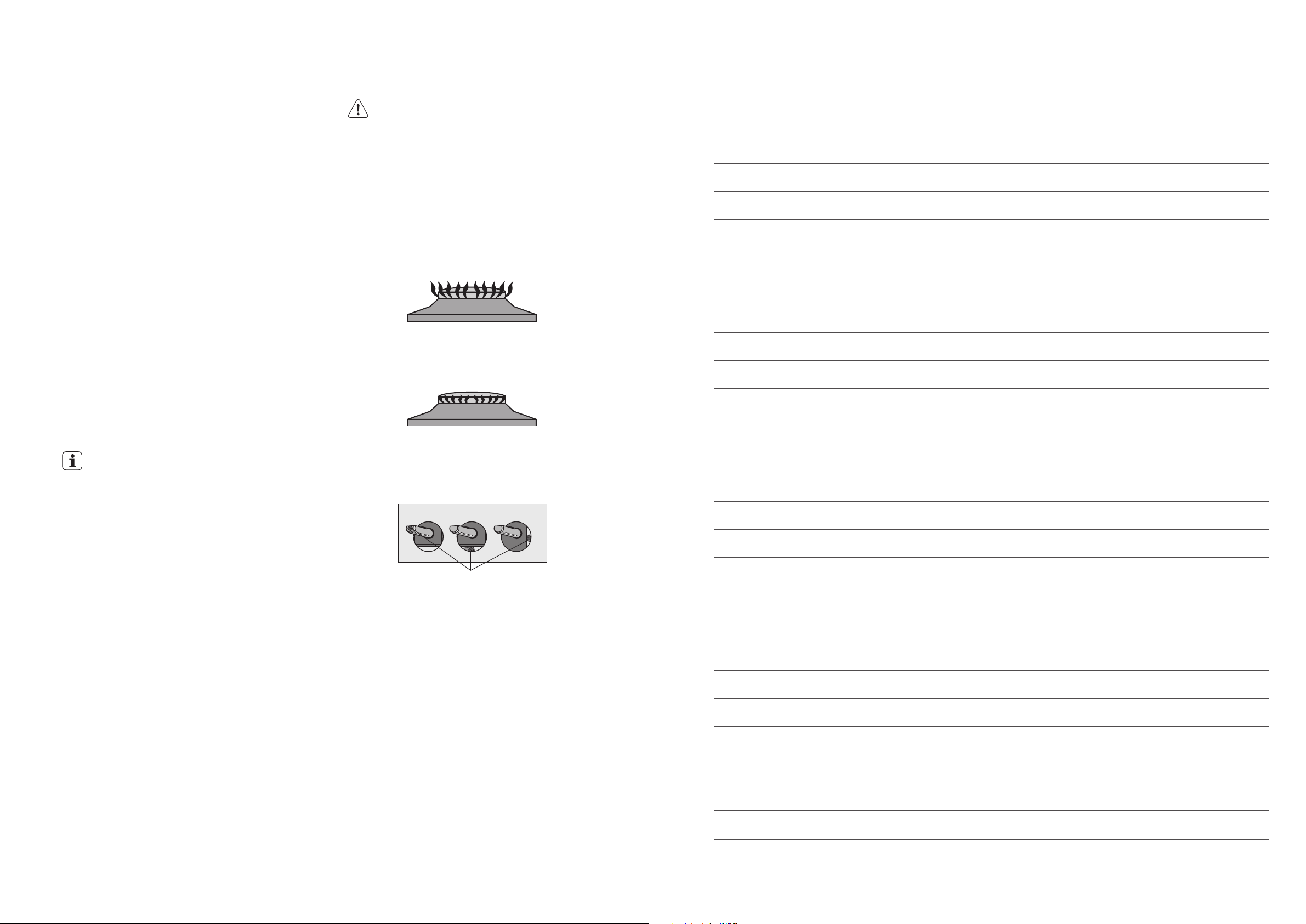
2. Observe the flame appearance on each burner
(Figure 11). If it is much larger or much smaller than
expected, the injector size and supply pressure
require checking. Where a flame is unsatisfactory,
refer to the Troubleshooting Guide (page 11) to
correct the fault. If the Troubleshooting Guide does
not solve the problem, call the Service Centre.
3. When all the foregoing is satisfactory, check the
turndown (minimum or low) setting on each burner,
as this may need adjustment. Valves have a bypass
controlling screw, which may be accessed by
removing the knob. This screw will be located on a
particular area of the valve (refer Figure 12). Normally,
this will have been correctly set at the factory for
use on Natural Gas (NG) and should not require
adjustment.
CAUTION
Servicing must only be carried out by an authorised
service person.
Injector sizes required for various gas types are shown in
Table 3 (page 26). The appliance test point pressure for each
gas type is also shown.
For model identification after installation, an additional data
plate sticker has been provided. This sticker is to be stuck
onto adjacent cabinetry.
Figure 11
NOTES
flame size adjusted to maximum
flame size adjusted to minimum
IMPORTANT
If the appliance has been converted to LPG, then
the bypass screw will HAVE to be screwed in until a
small, stable flame results.
Please ensure the supply pressure has been
checked PRIOR to any adjustment.
4. If the appliance cannot be adjusted to perform safely
inform the customer of the problem and affix an
appropriate warning notice to the appliance. If the
fault appears to be dangerous the appliance should
be disconnected. If a minor fault exists, the customer
may wish to use the appliance while awaiting service.
If a fault cannot be fixed, please call the
Service Centre.
5. The customer should be advised that, in the event
of a fault, the local service organisation or the
retailer from whom the appliance was purchased
should be contacted.
6. When satisfied that the unit is operating correctly,
turn off and instruct the customer on correct
operation as outlined in this booklet. Ask the
customer to operate the controls to ensure that
the correct procedure is understood.
Figure 12
bypass screw
Page 16

30 electrolux.com.au
Warranty
FOR SALES IN AUSTRALIA AND NEW ZEALAND
APPLIANCE: ELECTROLUX BUILT-IN OVENS, COOKTOPS AND
FREESTANDING COOKER
This document sets out the terms and conditions of the product
warranties for Electrolux Appliances. It is an important document.
Please keep it with your proof of purchase documents in a safe place
for future reference should there be a manufacturing defect in your
Appliance. This warranty is in addition to other rights you may have
under the Australian Consumer Law.
1. In this warranty:
(a) ‘ACL’ or ‘Australian Consumer Law’ means Schedule 2 to the
Competition and Consumer Act 2010;
(b) ‘Appliance’ means any Electrolux product purchased by you and
accompanied by this document;
(c) ‘ASC’ means Electrolux’s authorised serviced centres;
(d) ‘Electrolux’ is the brand controlled by Electrolux Home Products Pty
Ltd of 163 O’Riordan Street, Mascot NSW 2020, ABN 51 004 762
341 in respect of Appliances purchased in Australia and Electrolux
(NZ) Limited (collectively “Electrolux”) of 3-5 Niall Burgess Road, Mount
Wellington, in respect of Appliances purchased in New Zealand;
(e) ‘WarrantyPeriod’meanstheperiodspeciedinclause3ofthis
warranty;
(f) ‘you’ means the purchaser of the Appliance not having purchased
the Appliance for re-sale, and ‘your’ has a corresponding meaning.
2. Application: This warranty only applies to new Appliances, purchased
and used in Australia or New Zealand and is in addition to (and does not
exclude, restrict, or modify in any way) other rights and remedies under
a law to which the Appliances or services relate, including any nonexcludable statutory guarantees in Australia and New Zealand.
3. Warranty Period: Subject to these terms and conditions, this warranty
continues in Australia for a period of 24 months and in New Zealand
for a period of 24 months, following the date of original purchase of the
Appliance.
4. Repair or replace warranty: During the Warranty Period, Electrolux
or its ASC will, at no extra charge if your Appliance is readily accessible
for service, without special equipment and subject to these terms and
conditions, repair or replace any parts which it considers to be defective.
Electrolux may, in its absolute discretion, choose whether the remedy
oeredforavalidwarrantyclaimisrepairorreplacement.Electroluxorits
ASC may use refurbished parts to repair your Appliance. You agree that
any replaced Appliances or parts become the property of Electrolux.
5. Travel and transportation costs: Subject to clause 7, Electrolux will
bear the reasonable cost of transportation, travel and delivery of the
Appliance to and from Electrolux or its ASC. Travel and transportation will
be arranged by Electrolux as part of any valid warranty claim.
6. Proof of purchase is required before you can make a claim under this
warranty.
7. Exclusions: You may not make a claim under this warranty unless the
defect claimed is due to faulty or defective parts or workmanship. This
warranty does not cover:
(a) lightglobes,batteries,ltersorsimilarperishableparts;
(b) parts and Appliances not supplied by Electrolux;
(c) cosmeticdamagewhichdoesnotaecttheoperationofthe
Appliance;
(d) damage to the Appliance caused by:
(i) negligence or accident;
(ii) misuse or abuse, including failure to properly maintain or service;
(iii) improper, negligent or faulty servicing or repair works done by
anyone other than an Electrolux authorised repairer or ASC;
(iv) normal wear and tear;
(v) power surges, electrical storm damage or incorrect power supply;
(vi) incomplete or improper installation;
(vii) incorrect, improper or inappropriate operation;
(viii) insect or vermin infestation;
(ix) failure to comply with any additional instructions supplied with
the Appliance;
In addition, Electrolux is not liable under this warranty if:
(a) the Appliance has been, or Electrolux reasonably believes that the
Appliance has been, used for purposes other than those for which
the Appliance was intended, including where the Appliance has
been used for any non-domestic purpose;
(b) theApplianceismodiedwithoutauthorityfromElectroluxinwriting;
(c) the Appliance’s serial number or warranty seal has been removed
or defaced
8. How to claim under this warranty: To enquire about claiming under
this warranty, please follow these steps:
(a) carefully check the operating instructions, user manual and the terms
of this warranty;
(b) have the model and serial number of the Appliance available;
(c) have the proof of purchase (e.g. an invoice) available;
(d) telephone the numbers shown below.
9. Australia: For Appliances and services provided by Electrolux in
Australia: Electrolux goods come with guarantees that cannot be
excluded under the Australian Consumer Law. You are entitled to a
replacement or refund for a major failure and for compensation for any
other reasonably foreseeable loss or damage. You are also entitled to
have the Appliance repaired or replaced if the Appliance fails to be of
acceptable quality and the failure does not amount to a major failure.
‘Acceptable quality’ and ‘major failure’ have the same meaning as
referred to in the ACL.
10. New Zealand: For Appliances and services provided by Electrolux
in New Zealand, the Appliances come with a guarantee by Electrolux
pursuant to the provisions of the Consumer Guarantees Act, the Sale
of Goods Act and the Fair Trading Act. Where the Appliance was
purchased in New Zealand for commercial purposes the Consumer
Guarantee Act does not apply.
11.Condentiality: You accept that if you make a warranty claim, Electrolux
and its agents including ASC may exchange information in relation to you
to enable Electrolux to meet its obligations under this warranty.
Before calling for service, please ensure that the steps listed in clause 8 above have been followed.
FOR SERVICE
ortondtheaddressofyournearest
authorised service centre in Australia
PLEASE CALL 13 13 49
For the cost of a local call (Australia only)
FOR SERVICE
ortondtheaddressofyournearest
authorised service centre in New Zealand
PLEASE CALL 0800 10 66 10
(New Zealand only)
ECook_Warr_May17
Important Notice
AUSTRALIA
ELECTROLUX HOME PRODUCTS
163 O’Riordan Street, Mascot NSW 2020
electrolux.com.au
NEW ZEALAND
ELECTROLUX (NZ) Limited
3-5 Niall Burgess Road, Mount Wellington
electrolux.co.nz
FOR SPARE PARTS
ortondtheaddressofyournearest
spare parts centre in Australia
PLEASE 13 13 50
For the cost of a local call (Australia only)
FOR SPARE PARTS
ortondtheaddressofyournearest
spare parts centre in New Zealand
PLEASE 0800 10 66 20
(New Zealand only)
Page 17

32
Electrolux Home Products Australia
telephone: 1300 363 640
fax: 1800 350 067
email: [email protected]
web: electrolux.com.au
Electrolux Home Products New Zealand
telephone: 0800 436 245
fax: 0800 225 088
email: [email protected]
web: electrolux.co.nz
To add a touch of
professional inspiration
to your home,
visit electrolux.com.au
or electrolux.co.nz
shop.electrolux.com.au
electrolux.com.au
or electrolux.co.nz
P/No. ANC 305387219 Rev A
© 2021 Electrolux Home Products Pty Ltd.
ABN 51 004 762 341
E_MAN_GASCT_Oct21
 Loading...