

Page 1
user manual
Gas hob
EHG60412
Page 2
2 electrolux
Electrolux. Thinking of you.
Share more of our thinking at www.electrolux.com
CONTENTS
Safety information 2
Installation 4
Product description 8
Operating instructions 8
Helpful hints and tips 9
SAFETY INFORMATION
Warning! These instructions are only
valid in the countries whose symbols
appear on this booklet's cover.
For your safety and correct operation
of the appliance, read this manual
carefully before installation and use. Always keep these instructions with the
appliance even if you move or sell it.
Users must fully know the operation
and safety features of the appliance.
General safety
Warning! Persons (including children)
with reduced physical sensory, mental
capabilities or lack of experience and
knowledge must not use the appliance.
They must have supervision or
instruction for the operation of the
appliance by a person responsible for
their safety.
Child safety
• Only adults can use this appliance. Children must get supervision to make sure
that they do not play with the appliance.
• Keep all packaging away from children.
There is a risk of suffocation and physical
injury.
• Keep children away from the appliance
during and after the operation, until the
appliance is cold.
Use
• Remove all packaging, stickers and the
protective layer of the stainless steel hob
panel (if present) from the appliance before first use. Do not remove the rating
plate. It can invalidate the guarantee.
Care and cleaning 9
What to do if… 10
Technical data 11
Environment concerns 12
Subject to change without notice
• Set the cooking zones to the "off" position after each use.
• Burners and accessible part become hot
during and after use. Do not put cutlery
or saucepan lids on the cooking surface.
Cookware and its contents can tip over.
There is the risk of burns.
• Too hot fats and oils can ignite very
quickly. There is the risk of fire.
• Do not leave the appliance unattended
during operation.
• Always monitor the appliance during operation.
• Do not let the liquids overflow into the
holes of the top of the hob
• Do not use the hob without cookware.
• The appliance is only for domestic use.
Do not use the appliance for commercial
and industrial use.
• Only use the appliance for domestic
cooking tasks. This is to prevent physical
injury to persons or prevent damage to
property.
• Use only cookware with diameter applicable to the dimensions of burners. There
is a risk of overheating and rupture of the
glass plate (if applicable).
• Do not use a pan with diameter smaller
than burner dimension - flames will heat
up the pan handle.
• Pots must not enter the control zone.
• Do not use not stable cookware to prevent from tilt and accident.
• Do not put flammable products or items
that are wet with flammable products,
and/or fusible objects (made of plastic or
aluminium) and/or fabrics in, near or on
the appliance. There is the risk of explosion or fire.
Page 3

electrolux 3
• Use only the accessories supplied with
appliance.
• Be careful when you connect the appliance to the near sockets. Do not let electricity bonds touch the appliance or hot
cookware. Do not let electricity bonds
tangle.
Installation
• You must read these instructions.
The manufacturer is not responsible
for any injury to persons and pets or
damage to property caused by failure
to obey these requirements.
• To prevent the risks of structural
damage or physical injury, installation, connection of the appliance to
the power supply and gas system,
setting up and maintenance must only be done by qualified personnel in
compliance with standards and local
regulation force.
• Make sure that the appliance is not damaged because of transport. Do not connect a damaged appliance. If it is necessary, speak to the supplier.
• Only use built-in appliances after you assemble the appliance into correct built-in
units and work surfaces that obey the
standards.
• Do not install the hob over a domestic
appliances if the installation instructions
do not allow it.
• Install the appliance only on a worktop
with flat surface.
• Do not change the specifications or modify this product. There is the risk of injury
and damage to the appliance.
• Fully obey the laws, ordinances, directives and standards in force in the country where you use the appliance (safety
regulations, recycling regulations, electrical safety rules etc.)
• Keep the minimum distances to other appliances and units.
• Install anti-shock protection, for example
install the drawers only with a protective
panel directly below the appliance.
• Prevent damage of the cut surfaces of
the worktop against moisture with a correct sealant.
• Seal the appliance to the worktop with no
space left with a correct sealant.
• Prevent damage to the bottom of the appliance from steam and moisture, e.g.
from a dishwasher or oven.
• Do not install the appliance adjacent to
doors and below windows. Hot cookware can be hit off the hob when you
open the doors or windows.
• Before installation, make sure that the local supply conditions (gas type and pressure) agree with the adjustment of appliance. The adjustment conditions for the
appliance are on the rating plate, which
you can find near the gas supply pipe.
• This appliance is not connected to a
combustion products evacuation device.
It must be installed and connected in accordance with current installation regulations. Particular attention must be given
to the relevant requirements regarding
ventilation.
• The use of a gas cooking appliance
cause heat and moisture in the room
in which it is installed. Make sure
that the ventilation in the kitchen is
good: keep natural ventilation holes
open or install a mechanical ventilation device (mechanical extractor
hood).
More ventilation (for example open-
•
ing of a window or increasing the level of mechanical ventilation where
present) is necessary when you operate the appliance with intensity for a
long time.
• Carefully obey the instructions for electrical connections. There is the risk of injury
from electrical current.
• Disconnect the appliance from the
electrical supply, before you do the
maintenance work or you clean it.
• The electrical mains terminal is live.
• Make electrical mains terminal free of
voltage.
• Install correctly to give anti-shock protection.
• A loose and incorrect mains plug and
socket connections can make the terminal become too hot.
• A qualified electrician must install the
clamping connections correctly.
• Use a strain relief clamp on cable.
• Use the correct mains connection cable
and replace the damaged mains cable
Page 4
4 electrolux
with applicable cable. Speak to your local
Service Force Centre.
• The appliance must have the electrical installation which lets you disconnect the
appliance from the mains at all poles with
a contact opening width of minimum 3
mm.
• If the fixing bracket is near to the terminal
block, always make sure the connection
cable does not come in contact with the
edge of the bracket.
• You must have correct isolation devices:
line protecting cut-outs, fuses (screw
type fuses removed from the holder),
ground leakage trips and contactors.
INSTALLATION
Warning! The following instructions
about installation, connection and
maintenance must be carried out by
qualified personnel in compliance with
standards and local regulations in
force.
Important safety requirements
This hob must be installed in accordance
with the Gas Safety (Installation and Use)
Regulations (Current Edition) and the IEE
Wiring Regulations (Current Edition).
For appliances installed in the Republic of
Ireland please refer to NSAI- Domestic Gas
Installation I.S. 813 Current Editions and the
ETCI Rules for Electrical Installations.
Provision for ventilation
Detailed recommendations are contained in
the following British Standards Codes Of
Practice: B.S. 6172/ B.S. 5440, Par. 2 and
B.S. 6891 Current Editions.
The hob should not be installed in a bed sitting room with a volume of less than 20 m³.
If it is installed in a room of volume less than
5 m³ an air vent of effective area of 100 cm²
is required. If it is installed in a room of volume between 5 m³ and 10 m³ an air vent of
effective area of 50 cm² is required, while if
the volume exceeds 11 m³ no air vent is required.
However, if the room has a door which
opens directly to the outside no air vent is
required even if the volume is between 5 m³
and 11 m³.
If there are other fuel burning appliances in
the same room, B.S. 5440 Part 2 Current
Disposal of the appliance
• To prevent the risk of physical injury or
damage
– Disconnect the appliance from the
power supply.
– Cut off the mains cable where it con-
nects with the appliance and discard it.
– Flat the external gas pipes if there are
fitted.
– Speak to your local authorised facilities
for disposal of your appliance.
Edition, should be consulted to determine
the requisite air vent requirements.
For appliances installed in the Republic of
Ireland please refer to the NSAI- Domestic
Gas Installation I.S. 813 Current Editions
Table Four.
Location
The hob may be located in a kitchen, a
kitchen/diner or bed sitting room (with a
volume greater than 20 m³), but not in a
bathroom or shower room.
The minimum distance combustible material can be fitted above the hob in line with
the edges of the hob is 400 mm. If it is fitted below 400 mm a space of 50 mm must
be allowed from the edges of the hob.
For appliances installed in the Republic of
Ireland please refer to NSAI- Domestic Gas
Installation I.S 813 Current Edition Section
7- Permitted Locations of Appliance.
Gas Connection
Warning! Any gas installation must be
carried out by a GAS SAFE REGISTER
installer.
Make sure that, once the hob is installed, it
is easily accessible for the engineer in the
event of a breakdown.
The manufacturer will not accept liability,
should the above instructions or any of the
other safety instructions incorporated in this
instruction booklet be ignored.
On the end of the shaft, which includes the
G 1/2" threaded elbow, adjustment is fixed
so that the washer is fitted between the
Page 5
electrolux 5
components as shown in the diagram.
Screw the parts together without using excessive force.
1
2
3
1 End of shaft with nut
2 Washer
3 Elbow
Connection to the gas supply should be
with either rigid or semi-rigid pipe, i.e. steel
or copper.
The connection should be suitable for connecting to R 1/2 (1/2 BSP male thread).
When the final connection has been made,
it is essential that a thorough leak test is
carried out on the hob and installation.
Make sure that the main connection pipe
does not exert any strain on the hob.
If you use flexible metal pipes make sure
that they agree to ISO 10380 and ISO
10807 standards. Be careful they do not
come in touch with mobile parts or they are
not squeezed. Also be careful when the
hob is put together with an oven.
Important! It is important to install the
elbow correctly, with the shoulder on the
end of the thread, fitted to the hob
connecting pipe.
Important! Failure to ensure the correct
assembly will cause leakage of gas.
Important! Make sure that the gas supply
pressure of the appliance obeys the
recommended values.
Rigid connection:
Carry out connection by using metal rigid
pipes (copper with mechanical end).
Injectors replacement
1. Remove the pan supports.
2. Remove the caps and crowns of the
burner.
3. With a socket spanner 7 remove the injectors and replace them with the ones
which are necessary for the type of gas
you use (see table in Technical Data
section).
4. Assemble the parts, follow the same
procedure backwards.
5. Replace the rating label (it is near the
gas supply pipe) with the one for the
new type of gas supply. You can find
this label in the package of the injectors
supplied with the appliance.
If the supply gas pressure is changeable or
different from the necessary pressure, you
must fit an applicable pressure adjuster on
the gas supply pipe.
Adjustment of minimum level
To adjust the minimum level of the burners:
1. Light the burner.
2. Turn the knob on the minimum position.
3. Remove the control knob.
4. With a thin screwdriver, adjust the bypass screw position. If you change from
natural gas 20 mbar to liquid gas, fully
tighten the adjustment screw in. If you
change from liquid gas to natural gas 20
mbar, undo the by-pass screw approximately 1/4 of a turn.
1
1
Minimum adjustment screw
5. Make sure the flame does not go out
when you quickly turn the knob from the
maximum position to the minimum position.
Electrical connection
• Any electrical work required to install this
hob should be carried out by a qualified
electrician or competent person, in accordance with the current regulations.
• THIS HOB MUST BE EARTHED.
Page 6
6 electrolux
• Always use a correctly installed shockproof socket.
• Make sure that there is an access to the
mains plug after installation.
• Do not pull the mains cable to disconnect
the appliance. Always pull the mains
plug.
• The appliance must not be connected
with an extension cable, an adapter or a
multiple connection (risk of fire). Check
that the ground connection is in conformity with the standard and regulations
force.
• The power cable must be placed in such
a way that it does not touch any hot part.
• Connect the appliance to the mains with
a device that lets to disconnect the appliance from the mains at all poles with a
contact opening width of minimum 3
mm, eg. automatic line protecting cutout, earth leakage trips or fuse.
• None of a parts of the connection cable
can not get a temperature 90°C.
Electrical Requirements
Any permanent electrical installation must
comply with the latest I.E.E. Regulations
and local Electricity Board regulations. For
your own safety this should be undertaken
by a qualified electrician, e.g. your local
Electricity Board, or a contractor who is on
the roll of the National Inspection Council
for Electrical Installation Contracting (NICEIC).
The manufacturer declines any liability
should these safety measures not be
observed.
This hob is designed to be connected to a
230 V 50 Hz AC electrical supply.
Before switching on, make sure the electricity supply voltage is the same as that indicated on the hob rating plate. The rating
plate is located on the bottom of the hob.
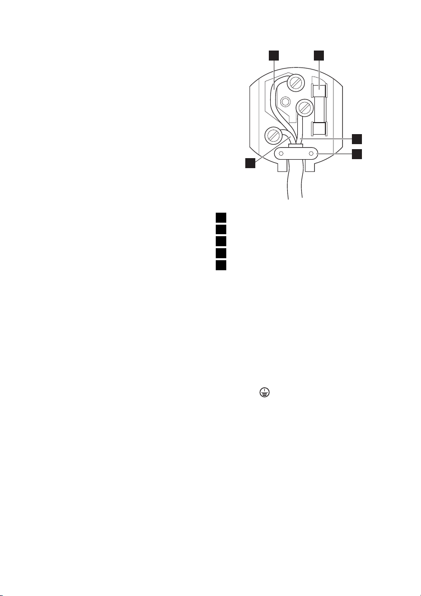
The hob is supplied with a 3 core flexible
supply cord incorporating a 3 amp plug fitted. In the event of having to change the
fuse, a 3 amp ASTA approved (BS 1362)
fuse must be used.
1 2
3
5
4
1 Green and Yellow
2 3 amp fuse
3 Brown
4 Cord clamp
5 Blue
Should the plug need to be replaced for
any reason, the wires in the mains lead are
coloured in accordance with the following
code:
Green and Yellow - Earth
Blue - Neutral
Brown - Live
1. Connect the green and yellow (earth)
wire to the terminal in the plug which is
marked with the letter 'E' or the earth
symbol
or coloured green and yel-
low.
2. Connect the blue (neutral) wire to the
terminal in the plug which is marked
with the letter 'N' or coloured black.
3. Connect the brown (live) wire to the ter-
minal in the plug which is marked with
the letter 'L' or coloured red.
Upon completion there must be no cut, or
stray strands of wire present and the cord
clamp must be secure over the outer
sheath.
Important! A cut off plug inserted into a 13
amp socket is a serious safety (shock)
hazard. Ensure that the cut off plug is
disposed of safely.
Page 7
electrolux 7
Important! The replacement of electric
cable must be carried out exclusively by the
service force centre or by personnel with
similar competencies, in accordance with
the current regulations.
sure that the cable section is applicable to
the voltage and the working temperature.
The yellow/green earth wire must be approximately 2 cm longer than the brown (or
black) phase wire.
Replacement of the connection cable
To replace the connection cable use only
H05V2V2-F T90 or equivalent type. Make
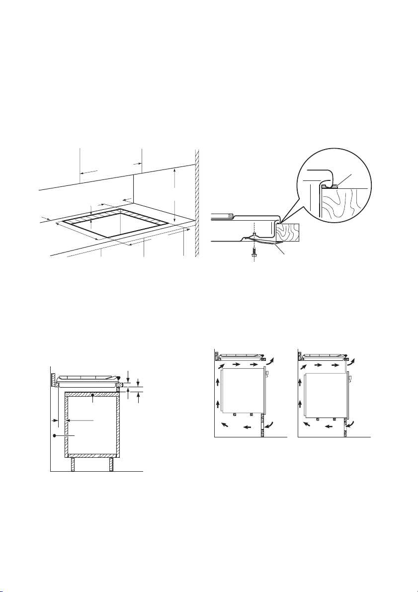
Building In
min. 600 mm
min. 100 mm
min. 55 mm
30 mm
470 mm
min. 650 mm
550 mm
A - supplied seal
B - supplied brackets
Possibilities for insertion
Kitchen unit with door
The panel installed below the hob must be
easy to remove and let an easy access in
case a technical assistance intervention is
equipped with vents to let a continuous
supply of air. The electrical connection of
the hob and the oven must be installed
separately for safety reasons and to let easy
remove oven from the unit.
necessary.
30 mm
50 cm
A
B
2
120 cm
2
a
60 mm
b
min 20 mm
(max 150 mm)
a) Removable panel
b) Space for connections
Kitchen unit with oven
The hob recess dimensions must obey the
indication and the kitchen unit must be
2
360 cm
MANUFACTURER:
ELECTROLUX ITALIA S.p.A.
C.so Lino Zanussi, 30
33080 PORCIA (PN) - ITALIA
180 cm
2
Page 8
8 electrolux
PRODUCT DESCRIPTION
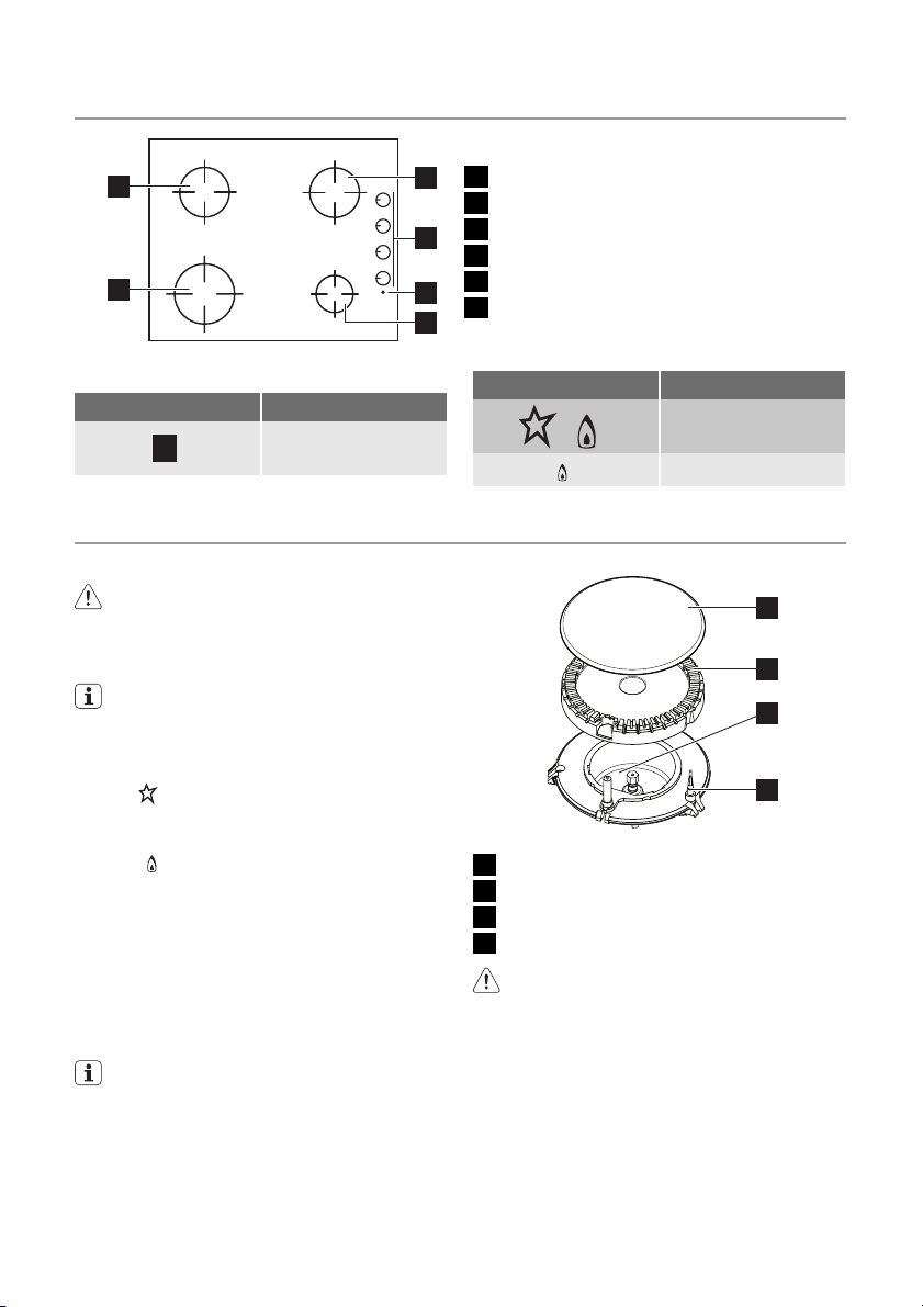
1
6
1 Semi-rapid burner
2
2 Semi-rapid burner
3 Control knobs
3
4 Spark generator button
5 Auxiliary burner
4
6 Rapid burner
5
Control knobs
Symbol Description
no gas supply / off
position
OPERATING INSTRUCTIONS
Ignition of the burner
Warning! Be very careful when you
use open fire in kitchen environment.
Manufacturer decline any responsibility
in case misuse of the flame
Always light the burner before you put
cookware.
To light the burner:
1. Push and hold the spark generator button
2. At the same time turn the control knob
3. Release the spark generator button
4. Adjust the flame after it is regular.
.
counterclockwise to the maximum posi-
and push it down to light the
tion
burner.
when burner lights but keep the control
knob on this position for approximately
5 seconds; this will let thermocouple to
warm up. If not, the gas supply will be
interrupted.
If after some tries the burner does not
light, check if the crown and its cap are
in correct positions.
Symbol Description
ignition position /
maximum gas supply
minimum gas supply
1
2
3
4
1 Burner cap
2 Burner crown
3 Ignition candle
4 Thermocouple
Warning! If the burner does not light
after 15 seconds, release the control
knob, turn it into off position and try to
light the burner again after minimum 1
minute.
Important! In the absence of electricity you
can ignite the burner without electrical
device; in this case approach the burner
with a flame, push the relevant knob down
and turn it counter-clockwise to maximum
gas release position.
Page 9
electrolux 9
If the burner accidentally goes out, turn
the control knob to the off position and
try to light the burner again after minimum 1 minute.
The spark generator can start automatically when you switch on the mains,
after installation or a power cut. It is
normal.
HELPFUL HINTS AND TIPS
Energy savings
• If possible, always put the lids on the
pans.
• When the liquid starts to boil, turn down
the flame to barely simmer the liquid.
Warning! Use pots and pans with
bottom applicable to the dimension of
burner.
Do not use cooking vessels on the hotplate that overlap its edges.
Burner Diameters of cookware
Rapid 180 - 260 mm
Semi-rapid 120 - 220 mm
Auxiliary 80 - 160 mm
Warning! Pots must not enter the
control zone.
Warning! Make sure pot handles do
not protrude over the front edge of the
Turning the burner off
To put the flame out, turn the knob to the
symbol
Do not place unstable or deformed pots on
the rings to prevent from spill and injury.
Information on acrylamides
Important! According to the newest
scientific knowledge, if you brown food
(specially the one which contains starch),
acrylamides can pose a health risk. Thus,
we recommend that you cook at the lowest
temperatures and do not brown food too
much.
.
Warning! Always turn the flame down
or switch it off before you remove the
pans of the burner.
cooktop and that pots are centrally
positioned on the rings in order to
achieve maximum stability and to
obtain lower gas consumption.
Warning! Flame diffuser are not
recommended.
CARE AND CLEANING
Warning! Switch the appliance off and
let it cool down before you clean it.
Disconnect the appliance from the
electrical supply, before carrying out
any cleaning or maintenance work.
Warning! For safety reasons, do not
clean the appliance with steam
cleaners or high-pressure cleaners.
Warning! Do not use abrasive
cleaners, steel wool pads or acids, they
can cause damage to the appliance.
• You can remove the pan supports to
easily clean the hob.
• To clean the enamelled parts, cap and
crown, wash it with warm soapy water.
• Stainless steel parts wash with water,
and then dry with a soft cloth.
• The pan supports are not dishwasher
proof; they must be washed by hand.
• When you wash the pan supports by
hand, take care when you dry them as
the enamelling process occasionally
leaves rough edges. If necessary, remove
stubborn stains using a paste cleaner.
• Make sure you position the pan supports
correctly after cleaning.
• To make burners work correctly, make
sure that the arms of the pan supports
are in the centre of the burner.
• Be very careful when you replace the
pan supports to prevent the hob top
from damage.
Page 10
10 electrolux
After cleaning, dry the appliance with a soft
cloth.
The stainless steel can become tarnished if
it is too much heated. Refer to this you
must not cook with potstones, earthenware
pans or cast iron plates. Do not use aluminium foil to prevent damage the top during
operation.
Removing the dirt:
1. – Remove immediately: melting plas-
tic, plastic foil, and food containing
sugar.
Stop the appliance and let it cool
–
down before you clean: limescale
rings, water rings, fat stains, shiny
metallic discolorations. Use a special
2. Clean the appliance with a damp cloth
and some detergent.
3. At the end rub the appliance dry with
a clean cloth.
Cleaning of the spark plug
This feature is obtained through a ceramic
ignition candle with a metal electrode. Keep
these components well clean to prevent difficult lighting and check that the burner
crown holes are not obstructed.
Periodic maintenance
Periodically speak your local Service Force
Centre to check the conditions of the gas
supply pipe and the pressure adjuster, if fitted.
cleaner for glass or stainless steel.
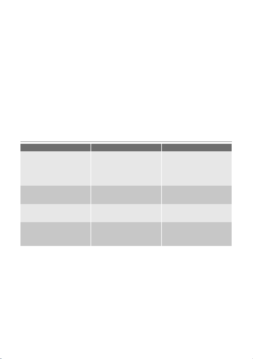
WHAT TO DO IF…
Problem Possible cause Remedy
There is no spark when lighting
the gas
• Burner cap and crown are
The flame is blow out immediately after ignition
The gas ring burns unevenly • Burner crown is blocked with
• There is no electrical supply • Make sure that the unit is
placed uneven
• Thermocouple is not heated
sufficient
food residues
connected and the electrical
supply is switched on.
• Control the fuse. If the fuse is
released more than one time,
refer to a qualified electrician.
• Make sure that the burner
cap and crown are in correct
positions.
• After lightning the flame,
keep the knob pushed for
approximately 5 seconds.
• Make sure that the injector is
not blocked and the burner
crown is clear of food particles.
Page 11
electrolux 11
If there is a fault, first try to find a solution to
the problem yourself. If you cannot find a
solution to the problem yourself, speak your
dealer or the local Service Force Centre.
If you operated the appliance incorrectly, or the installation was not carried
out by a registered engineer, the visit
from the customer service technician or
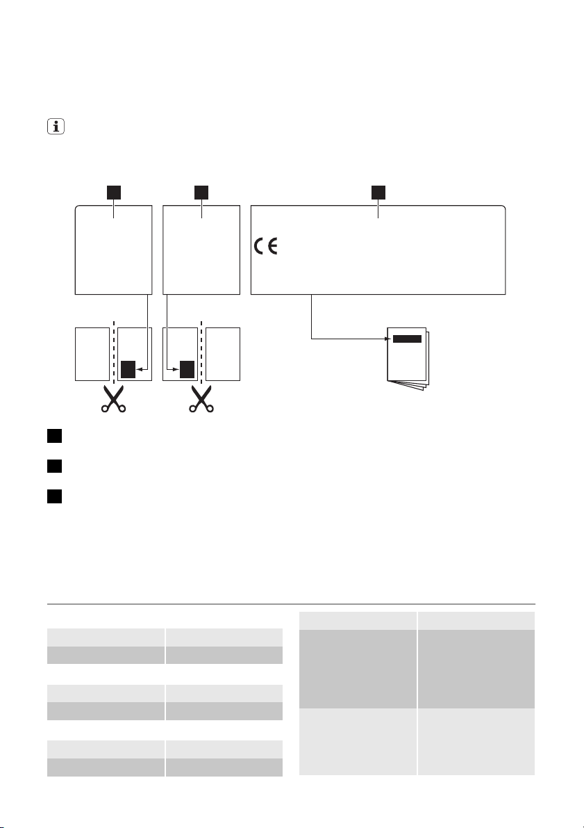
1 2 3
MOD.
PROD.NO.
SER.NO
DATA
MOD.
PROD.NO.
SER.NO
DATA
MODELMODEL
03 IT
MADE IN ITALY
1 Stick it on Guarantee Card and send
this part
2 Stick it on Guarantee Card and keep
this part
3 Stick it on instruction booklet
These data are necessary to help you
quickly and correctly. These data are
available on the identification plate
from the injectors kit.
• Model description .................
dealer may not take place free of
charge, even during the warranty period.
Labels supplied with the accessories
bag
Stick the adhesive labels as indicated below:
0049
MOD.
PROD.NO.
SER.NO.
TYPE
230V-50Hz
IP20
• Product number (PNC) .................
• Serial Number (S.N.) .................
Use the original spare parts only. They are
available at Service Force Centre and approved spare parts shops.
TECHNICAL DATA
Hob dimensions
Width: 580 mm
Length: 500 mm
Hob recess dimensions
Width: 550 mm
Length: 470 mm
Heat input
Rapid burner: 3.0 kW
Semi-rapid burner: 2.0 kW
Auxiliary burner: 1.0 kW
TOTAL POWER: G20 (2H) 20 mbar = 8
kW
G30 (3+) 28-30 mbar
= 567 g/h
G31 (3+) 37 mbar =
557 g/h
Electric supply: 230 V ~ 50 Hz
3 core flexible cable
with non rewireable
plug fitted with a 3
amp cartridge fuse
Page 12
12 electrolux
Gas connection: R 1/2 "
Category: II2H3+
Gas supply: G20 (2H) 20 mbar
Appliance class: 3
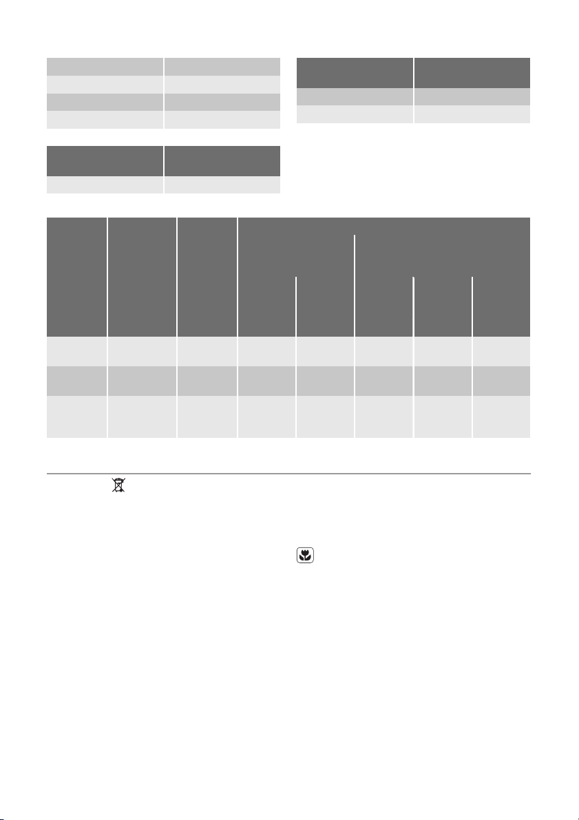
By-pass diameters
Burner Ø By-pass in 1/100
Auxiliary 28
mm.
Gas burners
REDUCED
POWER
0.75 119 0.286 86 204 200
NATURAL GAS
G20 (2H) 20 mbar
inj. 1/100
mm
BURNER
Auxiliary
burner
Semi-rapid burner
Rapid
burner
NORMAL
POWER
kW kW
1.0 0.33 70 0.095 50 73 71
2.0 0.45 96 0.190 71 145 143
3.0 (natural
gas)
2.8 (LPG)
ENVIRONMENT CONCERNS
The symbol on the product or on its
packaging indicates that this product may
not be treated as household waste. Instead
it should be taken to the appropriate
collection point for the recycling of electrical
and electronic equipment. By ensuring this
product is disposed of correctly, you will
help prevent potential negative
consequences for the environment and
human health, which could otherwise be
caused by inappropriate waste handling of
this product. For more detailed information
about recycling of this product, please
Burner Ø By-pass in 1/100
Semi-rapid 32
Rapid 42
NORMAL POWER
m³/h
(Butane/Propane) G30/G31 (3+)
inj. 1/100
28-30/37 mbar
mm
mm.
LPG
G30
28–30
mbar
g/h g/h
37 mbar
G31
contact your local council, your household
waste disposal service or the shop where
you purchased the product.
Packaging material
The packaging materials are friendly to
the environment and can be recycled.
The plastic components are identified
by marking: >PE<,>PS<, etc. Discard
the packaging materials as household
waste at the waste disposal facilities in
your municipality.
Page 13

electrolux 13
Page 14

14 electrolux
Page 15

electrolux 15
Page 16
www.electrolux.com/shop
397194901-B-482010
 Loading...