

Page 1
CZ-HR-SK-RO-SI
Gas hob - Gazovaà varoqnaà poverxnostì
INSTRUCTION BOOKLET
RUKOVODSTVO PO éKSPLUATACII
35686-9001
Mod. EHG 3760
Page 2
2
• This appliance has been designed to be operated by
adults and children under supervision. Young children
MUST NOT be allowed to tamper with the controls or
play near or with the oven.
• This appliance has been designed for cooking
edible foodstuff and to be used for domestic nonprofessional purposes only. It must not be used for
any other purpose.
• It is dangerous to alter the specification in any way.
• For hygiene and safety reasons, this appliance
should be kept clean at all times. A build-up of fats
or other foodstuff could result in a fire.
• Accessible parts of this appliance may become hot
when it is in use. Children should be KEPT AWAY until
it has cooled.
• Under no circumstances should you attempt to
repair the appliance yourself. Repairs carried out by
unexperienced persons may cause injury or serious
malfunctioning. Refer to your local Zanussi Service
Centre. Always insist on genuine Zanussi spare
parts.
• Ensure that all control knobs are in the OFF position
when not in use.
• Should you connect any electrical tool to a plug near
this cooking appliance, ensure that electric cables
are not in contact with it and keep them far enough
from the heated parts of this appliance.
• If the appliance is out of order, disconnect it from the
electric supply.
These instructions are only for the countries stated by the symbol
printed on the front cover of this instruction book.
This appliance complies with the following
E.E.C. Directives:
- 73/23 - 90/683 (Low Voltage Directive);
- 89/336
(Electromagnetical Compatibility Directive);
- 90/396 (Gas Appliances)
- 93/68 (General Directives)
and subsequent modifications.
During Operation
About Installation, Cleaning
and Manteinance
• It is mandatory that all operations required for the
installation are carried out by a qualified or competent
person, in accordance with existing rules and
regulations.
• Disconnect the appliance from the electrical supply,
before carrying out any cleaning or manteinance
work.
• Ensure a good ventilation around the appliance. A
poor air supply could cause lack of oxygen.
• Ensure that the gas supply complies with the gas
type stated on the identification label, placed near
the gas supply pipe.
• Using a gas cooking appliance will produce heat
and moisture in the room which it has been
installed in. Ensure a continuous air supply,
keeping the air vents in good conditions or
installing a cooker hood with discharge tube.
• In case of intensive or long time use of the
appliance, make the ventilation more efficient,
by opening a window or increasing the electric
exhaust fan power.
• Once you removed all packaging from the appliance,
ensure that it is not damaged and the electric cable
is in perfect conditions. Otherwise, contact your
dealer before proceeding with the installation.
• The manufacturer disclaims any responsability
should all the safety measures not be carried
out.
)
ENGLISH
MANUFACTURER:
ELECTROLUX HOME PRODUCTS ITALY S.p.A.
Viale Bologna 298 - 47100 FORLI’ (Italy)
For Your Safety
These warnings are provided in the interest of safety. You MUST read them carefully before
installing or using the appliance.
It is most important that this instruction book should be retained with the appliance for future
reference. Should the appliance be sold or transferred, always ensure that the book is left with
the appliance in order that the new owner can get to know the functions of the appliance and
the relevant warnings.
Page 3
3
1. Instruction for the User
HOB BURNERS CONTROL KNOBS
The hob burners control knobs are situated on the hob
front panel. The symbols on the knobs mean that :
z there is no gas supply
there is maximum gas supply
there is minimum gas supply
LIGHTING THE BURNERS
• For easier lighting, proceed before putting a pan
on the pan support.
Push the electric ignition push button which is marked
by a little spark ( ).
At the same time, turn the relevant control knob
anticlockwise to maximum position and keep it pushed
down for about 5 seconds. This will allow the
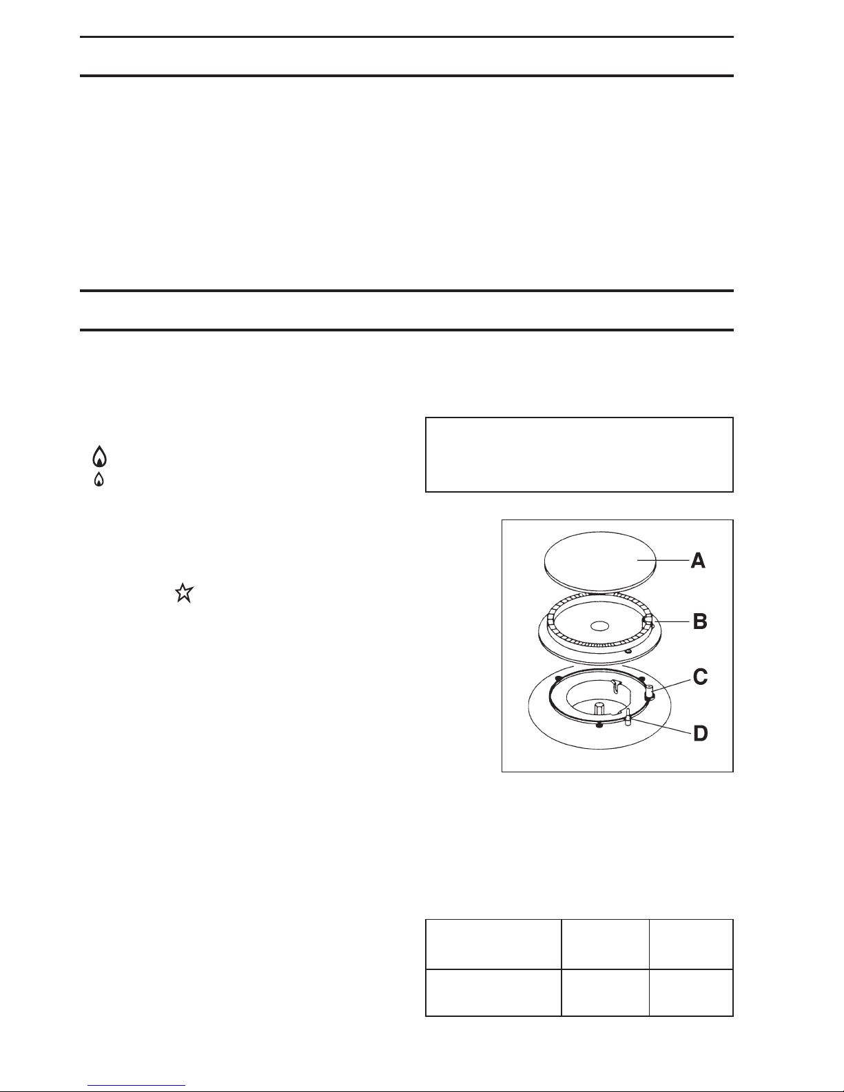
"thermocouple" (Fig. 1 lett. D) to be heated and the
safety device to be switched off, otherwise the gas
supply would be interrupted.
Then, check the flame is regular and adjust it as
required.
If you cannot light the flame even after several
attempts, check the "cap" (Fig. 1 lett. A) and the
"crown" (Fig. 1 lett. B) are in the correct position.
To put the flame out, turn the knob to the symbol z.
• Always turn the flame down or put it out before
taking the pans off the burner.
USING THE HOB CORRECTLY
To ensure maximum burner efficiency, it is strongly
recommended that you use only pots and pans with a
bottom fitting the size of the burner used, so that flame
will not spread beyond the bottom of the vessel (see the
table beside).
It is also advisable, as soon as a liquid starts boiling, to
turn down the flame so that it will barely keep the liquid
simmering.
• Use only pans or pots with flat bottom.
Carefully supervise cookings with fats or oil,
since these types of foodstuff can result in a fire,
if over-heated.
Burner minimum maximum
diameter diameter
Big (rapid) 180 mm 240 mm
Small (auxiliary) 80 mm 160 mm
Fig. 1
Contents
1. Instruction for the User ............ Pag. 3
2. Cleaning and Maintenance ...... Pag. 4
3. Service and original spare parts . Pag. 4
4. Technical Data........................... Pag. 4
5. Instruction for the Installer ...... Pag. 5
6. Electrical Connection ............... Pag. 6
7. Adaptation to different
types of gas ................................ Pag. 7
8. Building In .................................. Pag. 8
Table of minimum and maximum diameters of pots
which can be placed on the burners
FO 0204
A - Burner cap
B - Burner crown
C - Ignition candle
D - Thermocouple
Page 4
4
4. Technical Data
Gas Burners Rating
Rapid Burner (big) 3 kW (G20) - 2,8 kW (G30/31)
Auxiliary Burner (small) 1 kW
Category II 2H3+
Setting Natural Gas G 20 - 20 mbar
Gas connection G 1/2"
Electric Supply 230 V 50 Hz
HOB RECESS DIMENSIONS
Length 270 mm
Width 490 mm
2. Cleaning and Maintenance
• Disconnect the appliance from the electrical
supply, before carrying out any cleaning or
manteinance work.
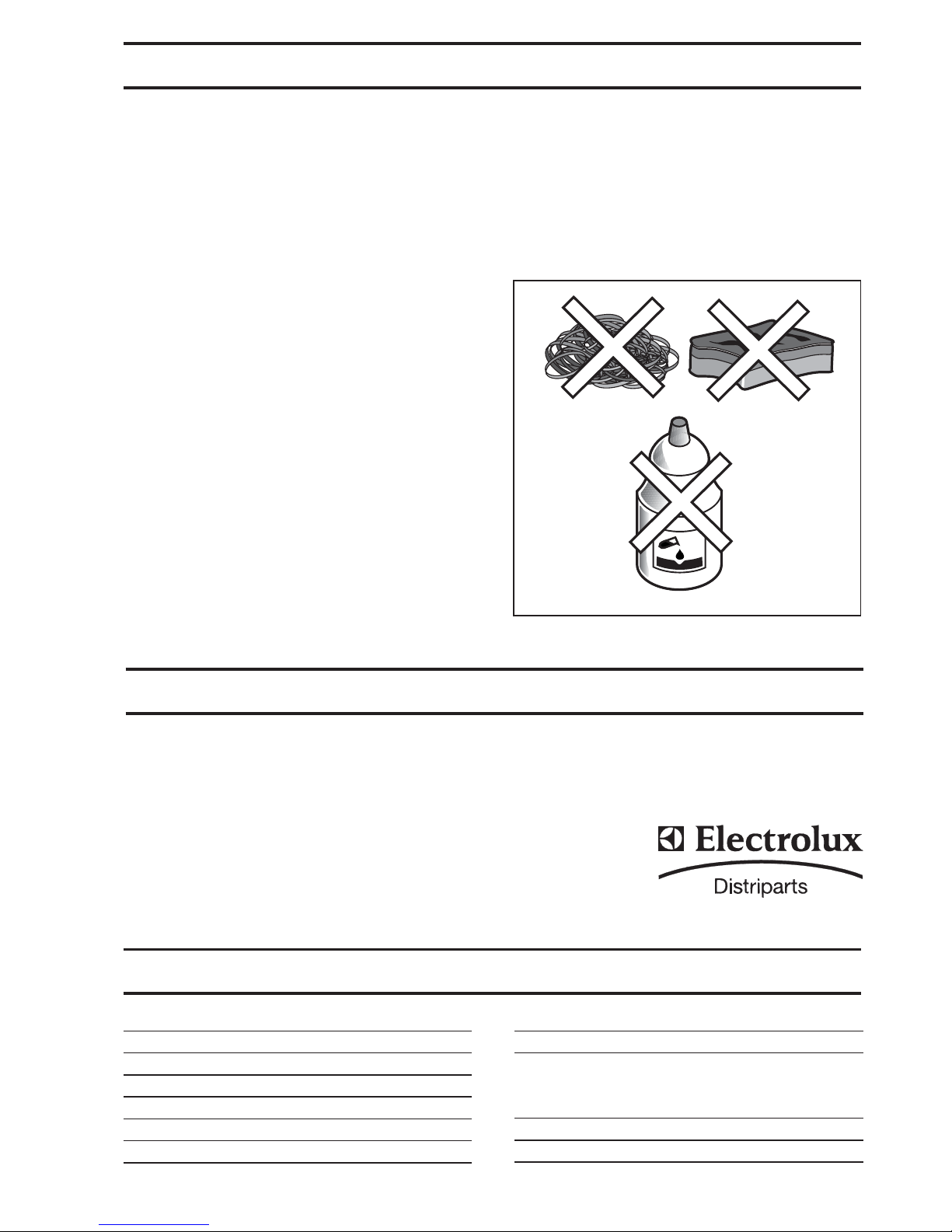
Wash the enamelled components with warm soapy
water. Never use abrasive cleaners
Frequently wash the "caps" and the "crowns" with hot
soapy water, carefully taking away any built-up of food.
Carefully wash the stainless steel components with
water, then wipe them dry with a soft cloth.
The pan supports are dishwasher proof.
If the marks are particularly difficult to remove, use
common non-abrasive cleaners or specific products.
Never use steel wool pads or acids.
In models provided with electric ignition, this feature
is obtained through a ceramic "candle" and a metal
electrode (Fig. 1 - lett. C). Keep these components well
clean, to avoid difficult lighting, and check that the
burner crown holes (Fig. 1 - lett. B) are not obstructed.
PERIODIC MAINTENANCE
Periodically ask your local Service Centre to check the
conditions of the gas supply pipe and the pressure
adjuster, if fitted.
To ensure the good operation of the hob and its safety
features, it is necessary that the taps are periodically
lubricated.
zz
zz
z The periodic lubrication of the taps must be
carried out by qualified personnel, which you
must refer to also in case of malfunctioning.
Fig. 2
FO 2110
This machine, before leaving the factory, has been
tested and studied by many experts and specialists, in
order to give you the best results.
Any repair work which needs to be carried out should be
done with the utmost care and attention.
For this reason we recommend that for any problem you
contact the dealer who sold it to you, or our nearest
authorized Service Centre, specifying the nature of the
problem, the appliance model (Mod.), the product
number (Prod. No.) and the serial number (Ser. No.)
marked on the identification plate.
3. Service and original spare parts
Original spareparts, certified by the product
manufacturer and carrying this symbol are only available
at our Service Centre and authorized spareparts shops.
Page 5
5
5. Instruction for the Installer
zz
zz
z The following instructions about installation and
maintenance must be carried out by qualified
personnel in compliance with the regulation in
force.
zz
zz
z The side walls of the unit in which the hob is
going to be installed, must not exceed the height
of the working top.
zz
zz
z Avoid installing the appliance in the proximity of
inflammable materials (e.g. curtains, tea towels
etc.).
zz
zz
z The appliance must be electrically disconnected
before all interventions. If any electric supply to
the appliance is required to carry out the work,
ensure all the necessary precautions are followed.
IMPORTANT - To ensure a correct operation, a saving
of energy and the long-life of the appliance, the feeding
pressure of the appliance must correspond to the
recommended values.
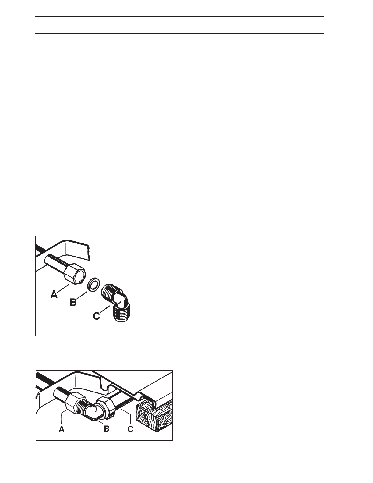
The adjustable connection is fixed to the comprehensive
ramp by means of a threaded nut G 1/2". Interpose the
sealing between the components as shown in Fig. 3.
Screw the parts without forcing, adjust the connection in
the required direction and tighten everything.
The adjustable connection allows the feeding pipe to be
situated in the site purposefully allocated on the side of
the protection box of the hob itself (Fig. 4). This
connection allows the overall dimensions of the hob
plus the fedding pipe to be contained into a depth of 30
mm.
IMPORTANT - When the final connection has been
made, it is essential that a thorough leak test is carried
out on the hob and installation. Use some soapy water,
never a flame.
A) Ramp with ending nut
B) Seal
C) Adjustable connection
Fig. 3
FO 0264
Fig. 4
A) Ramp ending with nut
B) Adjustable connection
C) Rigid or flexible metallic gas pipe
FO 0265
Page 6
6
The appliance is designed to be connected to 230 V
monophase electricity supply.
The connection must be carried out in compliance with
the laws and regulations in force.
Before the appliance is connected:
1) check that the main fuse and the domestic installation
can support the load (see the rating label);
2) check that the power supply is properly earthed in
compliance with the current rules;
3) check the socket or the double pole switch used for
the electrical connection can be easily reached with
the appliance built in the forniture unit.
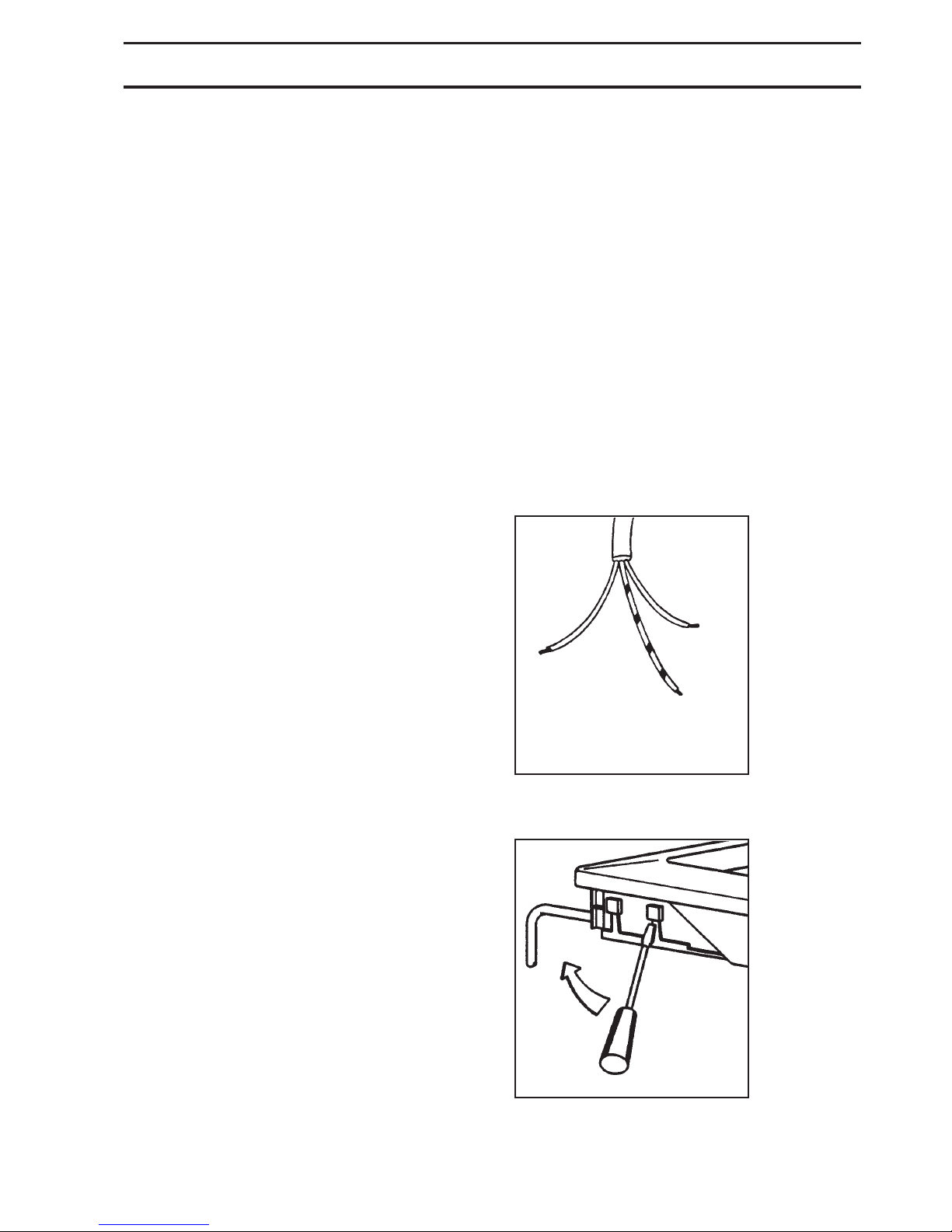
The appliance is supplied with a connection cable. This
has to be provided with a proper plug, able to support the
load marked on the identification plate. To connect the
plug to the cable, follow the recommendation given in
Fig. 5. The plug has to be fitted in a proper socket.
If connecting the appliance directly to the electric
system, it is necessary that you install a double pole
switch between the appliance and the electricity supply,
with a minimum gap of 3 mm between the switch contacts
and of a type suitable for the required load in compliance
with the current rules.
The connection cable has to be placed in order that, in
each part, it cannot reach a temperature 90 °C higher
than the room temperature.
The brown coloured phase cable (fitted in the terminal
block contact marked with "L") must always be connected
to the network phase.
REPLACEMENT OF THE VOLTAGE CABLE
The connection of the voltage cable to the appliance's
terminal block is of type "Y". This means that its
replacement requires the specific equipment of a
technician.
In this case, only cable type H05V2V2-F T90 must be
used. The cable section must be suitable to the voltage
and the working temperature.
The yellow/green earth wire must be approximately 2
cm. longer than the phase wires (Fig. 5).
To open the terminal block and reach the terminals,
proceed as follows:
z insert the point of a screwdriver into the visible
protrunding part of the terminal block;
z exert a light pressure and lift (Fig. 6)
6. Electrical Connection
Fig. 5
Fig. 6
FO 0073
FO 0257
Neutral
Earth (yellow/green)
Page 7
7
INJECTORS REPLACEMENT
• Remove the pan supports.
• Remove the burner's caps and crowns.
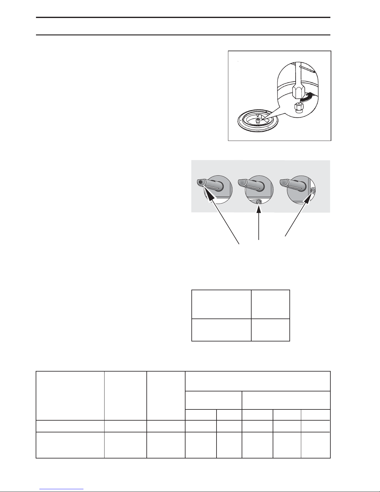
• With a socket spanner 7 unscrew and remove the
injectors (Fig. 7), and replace them with the ones
required for the type of gas in use (see table 2).
• Reassemble the parts, following the same procedure backwards.
• Replace the rating label (placed near the gas supply
pipe) with the relevant one for the new type of gas
supply. You can find this label in the package of the
injectors supplied with the appliance.
Should the feeding gas pressure be different or
variable compared with the required pressure, an
appropriate pressure adjuster must be fitted on the gas
supply pipe, in compliance with the rules in force.
7. Adaptation to different types of gas
Fig. 7
FO 0392
ADJUSTMENT OF MINIMUM LEVEL
To adjust the minimum level of the burners, proceed as
follows:
• Light the burner.
• Turn the knob on the minimum position.
• Remove the knob.
• With a thin screwdriver, adjust the by-pass screw (see
Fig. 8 ). If changing from natural gas to LPG, completely
tighten clockwise the screw, until a small regular
flame is obtained.
• Finally check the flame does not go out when quickly
turning the knob from the maximum position to the
minimum position.
This procedure can easily be carried out, anyhow the
hob has been positioned or built in the working top.
BURNER NORMAL REDUCED NORMAL
POWER POWER POWER
kW kW NATURAL GAS LPG
G20 - 20 mbar 28-30/37 mbar
inj. 1/100 m3/h inj. 1/100 g/h - G30 g/h - G31
Auxiliary (small) 1 0,33 70 0,095 50 73 71
Natural gas :
Rapid (big) 3 0,65 119 0,286 86 203 200
LPG : 2,8
Burner Ø By-pass
in 1/100
of mm.
Auxiliary 28
Rapid 40
Table 1 : By-pass diameters
Table 2 : injectors
Fig. 8
by-pass screw
Page 8
8
8. Building In
A = Auxiliary burner
R = Rapid Burner
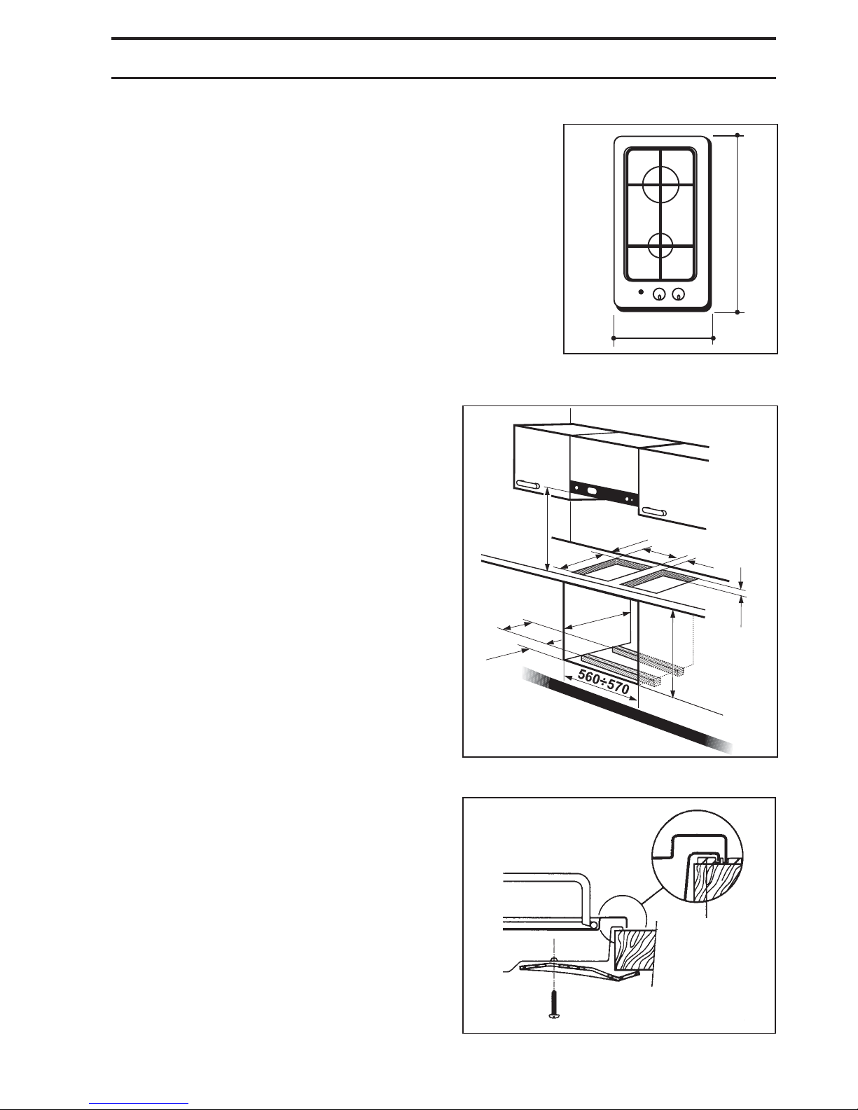
These hobs can be inserted in a built-in kitchen unit
whose depth is between 550 and 600 mm. The hobs
dimensions are shown in Fig. 9.
INSTALLATION AND ASSEMBLY
These hobs can be installed in a kitchen unit with an
opening for insertion whose dimensions are shown in
Fig. 10.
Carry out the building in of the hob as follows:
• put the relevant sealings, supplied with the hob, on
the edges of the cut out, taking care that the sealings
meet without overlapping;
• place the hob in the cut out, taking care of its
centring;
• fix the hob with the relevant screws (Fig. 11). The
traction of the screws is able to trace the sealing, any
excess of which can then be easily removed.
The edge of the hob forms a double labyrinth seal
which provides a total guarantee against infiltration of
liquids.
If several function are to be combined (2 burners hob
+ fish kettle burner + 2 plates hob) follow the
recommendations given in Fig. 10, which indicates the
minimum distance to be observed between the various
openings to be cut on the surface of the unit.
Fig. 11
FO 0199
a
a) sealing
Fig. 9
FO 0952
Fig. 10
R
A
510
290
550 MIN
591
140
240
490
55
270
40÷50
30
650 MIN.
Page 9
9
POSSIBILITIES FOR
INSERTION
Kitchen unit with door
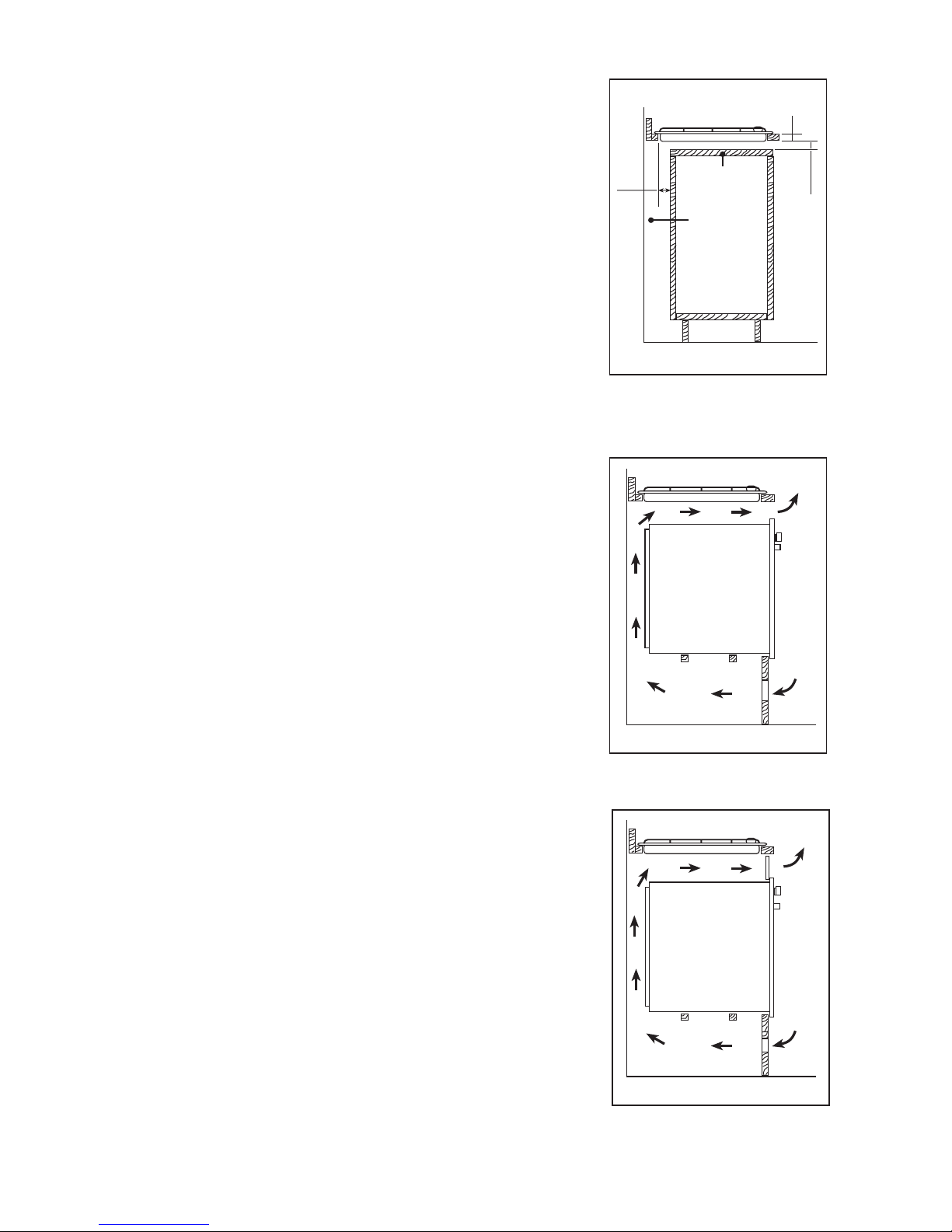
Proper arrangements must be taken in designing the
forniture unit, in order to avoid any contact with the
bottom of the hob which can be heated when it is
operated. The recommended solution is shown in Fig. 12.
The panel fitted under the hob should be easily removable
to allow an easy access if a technical assistance
intervention is needed.
Kitchen unit with oven
The hob recess dimensions must comply with the
indication given in Fig. 10 and must be provided with
openings to allow a continuous supply of air.
To avoid overhating, the building in should be carried out
as shown in Figs. 13 and 14.
The hob's electric connection and the oven's one must
be carried out separately, both for safety reasons and to
allow the oven to be easily taken off the unit.
Hanging forniture units or hoods must be placed at 650
mm minimum from the hob (Fig. 10).
a) Removable panel
b) Space possibly useful for
connections
Fig. 12
Fig. 13
Fig. 14
FO 2103
FO 2104
FO 2105
30
20 min
60
a
b
50 cm
2
360 cm
2
120 cm
2
180 cm
2
 Loading...