

Page 1
Bruksanvisning, Käyttöohje
User Manual
EFT 500
✐ ✑ ✒ ✓ ✐ ✩
S
1
FIN
UK
Page 2

18
Contents
Safety instructions............................................................................................................... 19
Description of the appliance ............................................................................................... 20
Standard accessories included: ..............................................................................................................................20
Exhausting .............................................................................................................................................................20
Recycling ...............................................................................................................................................................20
Special accessories ............................................................................................................. 21
Installation ............................................................................................................................ 21
Unpacking..............................................................................................................................................................21
Placement ..............................................................................................................................................................21
Electrical connection .............................................................................................................................................21
Mounting of hood on wall .....................................................................................................................................21
Mounting under cupboard .....................................................................................................................................22
Exhausting mode ...................................................................................................................................................22
Recirculation mode (with carbon filter) ................................................................................................................22
Using the hood ..................................................................................................................... 22
Speed regulation ....................................................................................................................................................22
Work light ..............................................................................................................................................................23
Correct ventilation .................................................................................................................................................23
Important to know .................................................................................................................................................23
Maintenance ......................................................................................................................... 23
Grease filter ...........................................................................................................................................................23
Carbon filter...........................................................................................................................................................23
Cleaning.................................................................................................................................................................24
Changing the lighting elements .............................................................................................................................24
If the hood does not function.............................................................................................. 24
Service and spare parts....................................................................................................... 24
Technical data ...................................................................................................................... 25
Page 3

19
Congratulations to your new Cooker Hood
Thank you for your choice of an Electrolux product. We are convinced that you will have
great use and pleasure from your new cooker hood.
Before you use the cooker hood we recommend that you read through the whole user
manual giving a direct description of the cooker hood and its functions.
To avoid the risks, that are always present when you use a product driven by electricity, it
is important that the cooker hood is installed correctly and that you read the safety instructions carefully to avoid misuse and hazard.
Save the instruction manual and keep it available at use of the cooker hood
Safety instructions
At installation and service
● The cooker hood is made for normal households
with normal cooking. If it is used for other
purposes there is a risk of damage which is not
covered by the warranty.
● All eventual electric installation has to be
carried out by a qualified electrician. The
installation of the hood should be made by a
person with enough knowledge. Installation
made otherwise could lead to loss of performance and even injuries and /or damage on
properties.
● The hood cannot be connected to flues of other
appliances that run on energy sources other than
electricity.
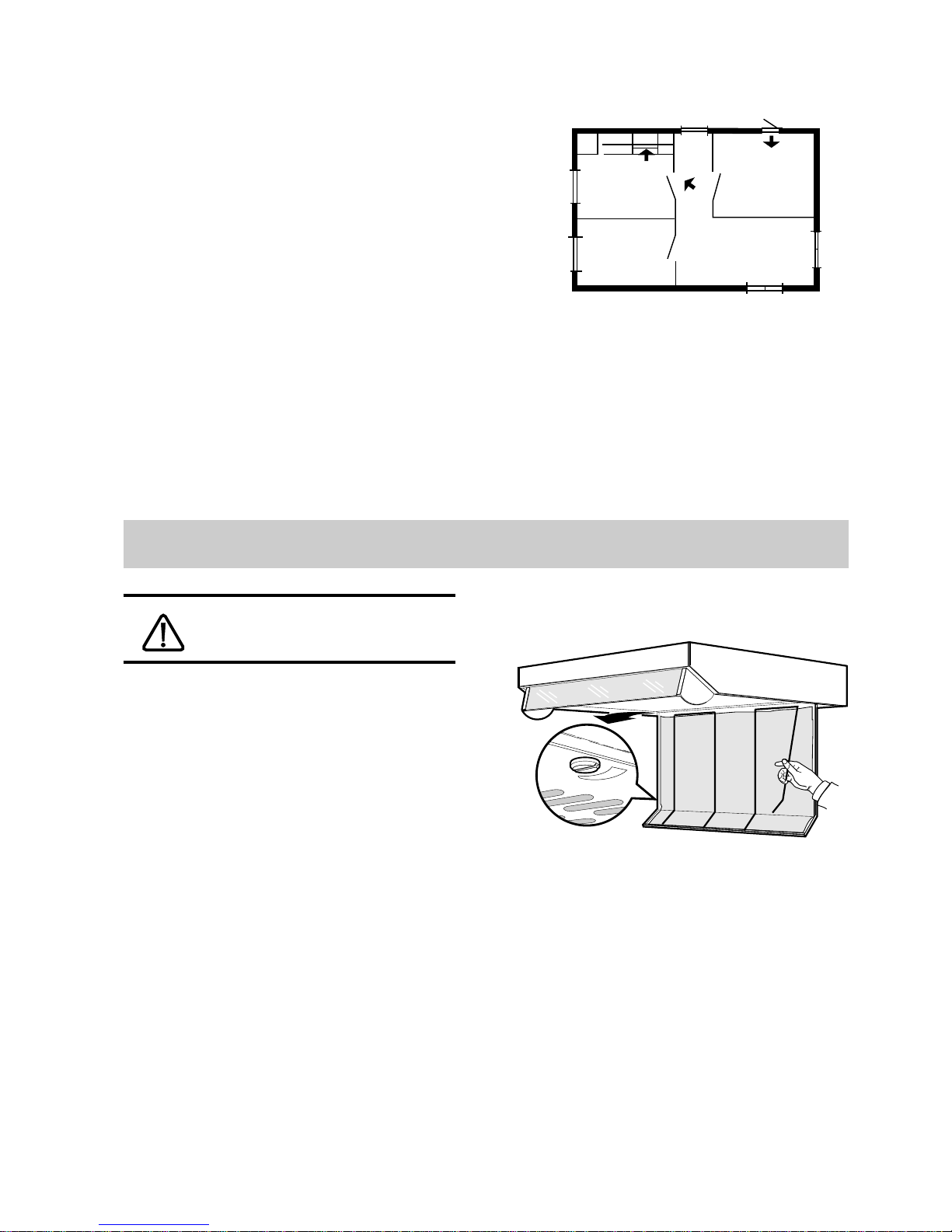
Please, keep to the provisions of official directives regarding the question of fumes discharge.
● When the hood is used at the same time of other
appliances that run on energy sources other than
electricity, provision must be made for an
adequate supply of air.
● When installed, the hood must be not less than
65 cm. above electric burners or 75 cm. above
gas or mixed-fuel burners. (Fig. 3).
● The power cord should be drawn so that there is
no risk of damage. Hazard!
At use of cooker hood
● No food must be cooked flambé underneath the
hood.
● The use of an unprotected flame is dangerous
for the filters and could cause fires.
● Never leave the deep-frying or frying pan over a
cooker/hob. The oil contained in the pan may
spontaneously ignite through overheating.
● Observe the filter change or cleaning intervals.
Failure to observe these intervals may cause the
risk of fire through fat deposition.
Note! If a fire starts; Switch of the cooker hood
and the heating zone; Cover the fire , Never use
water.
At disposal
● Help to avoid damages even when the cooker
hood should be disposed. Disconnect the power
plug and cut the power cord at hood inlet. Check
with the authorities for information of how to
proceed for disposal.
Page 4
20
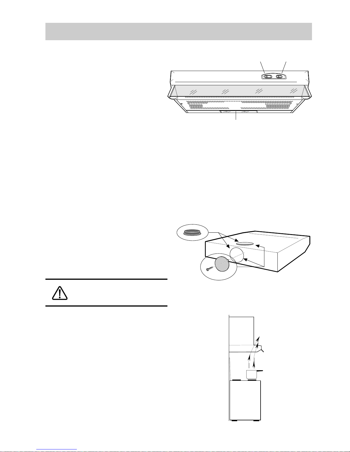
1. Light switch
2. Motor speed switch
3. Work light
4. Suction grid with grease filter
Standard accessories included:
● Template for mounting on wall and under
cupboard
● Screws for mounting
● Duct Ø 120 with no return valve
● Cap Ø 100
Function
The hood may be used as follows:
- For air exhausting
- For air recycling
Exhausting
The appliance has two exhaust outlets; D and E
(Fig. 2).
Connect the hood to the smoke exhaust hose by
using the connecting ring G with no return valve.
Insert plug H in the unused exhaust hole (bayonet
coupling).
Plug H is for closing the unused hole.
Attention! In the horizontal runs the duct must be
slightly slanted (about 10°) and directed upwards
to vent the air easily from the room to the outside.
The hood cannot be connected to flues
of other appliances that run on
energysources other than electricity.
Recycling
The air is filtered through a carbon filter and
recirculated into the room through the front grid
(fig. 3).
This version is used when there is no exhaust duct
for venting outdoors or when it is impossible to
install one.
Description of the appliance
Fig. 3
Fig. 1
Fig. 2
E
D
H
G
✐ ✑ ✒ ✓ ✐ ✩
1
2
4
3
Page 5
21
Unpacking
Check that the cooker hood has no damages. Transportation damages should immediately be reported
to the one responsible for the transport Damages,
faults and eventually missing details should immediately be reported to the seller.
Take care of the packing material so that small
children cannot play with it.
Placement
The hood is to be mounted on the wall or under a
wall cupboard.
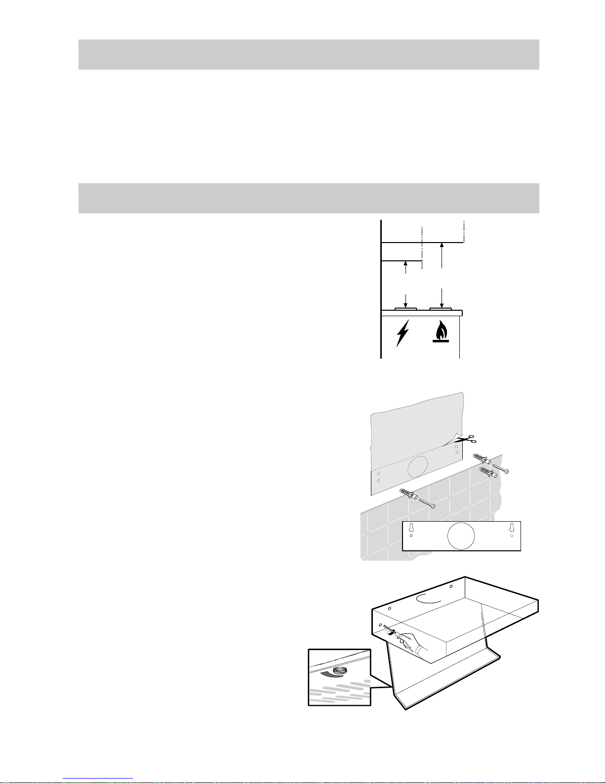
When installed, the hood must be not less than 65
cm. above electric burners or 75 cm. above gas or
mixed-fuel burners. (Fig. 4).
Electrical connection
The hood has a power cord with moulded plug with
earth connection to be connected to a wall outlet of
230 V.
The power cord length is 1,2 m.
Mounting of hood on wall
● Fix the drilling template to the wall (Fig. 5).
● Make 3 Ø 8 mm holes in the wall. 2 at points I, 1
as desired at points L.
● Insert the three Ø 8 mm expansion plugs into the
wall.
● Insert 2 5x45 screws at points I but do not tighten
them completely.
● Open the grid.
● Fit the hood into holes I, tighten the 2 screws.
● From inside the hood, insert the third 5x45 screw
into hole L (Fig. 6).
Installation
Special accessories
Active carbon filter
When the hood is used in recirculation mode an
active carbon filter should be used.
Order by the retailer
PNC 955 101 117
Flex tube kit
When the hood is to be connected to an evacuation
channel use the flex tube kit containing one evacuation flex tube, one roof connecting duct and two
tube clamps.
Order by the retailer.
PNC 391 414 201
Fig. 4
Fig. 5
Min
75 cm
Min
65 cm
I
I
L
L
I
I
L
Fig. 6
Page 6
22
Mounting under cupboard
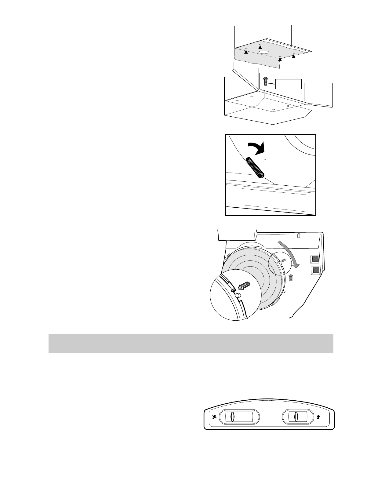
● Make the holes on the bottom of the cupboard,
using the drilling template (Fig. 7).
● From inside the cupboard, insert the 4 supplied
screws and tighten them in the appropriate holes
on the appliance.
Exhausting mode
● Connect the air outlet to the smoke exhaust hose
● Open the suction grid (Fig. 12).
● Check that the selection lever for evacuation/
recycle is in the position A - external evacuation. (Fig. 8).
● Refit the suction grid.
Recirculation mode (with carbon
filter)
The air outlets D (Fig. 2) must be shut with plug H.
● Open the suction grid (Fig. 12).
● Check that the selection lever for evacuation/
recycle is in the position : F - recycle (Fig. 8)
● Place the carbon filter so to cover the fan
housing.
The plastic reference on carbon filter must
match the arrow printed on the fan housing.
Rotate clockwise until stop (Fig. 9).
● Refit the suction grid.
Using the hood
The control panel is located on the front part of the
hood.
Speed regulation
The hood has a three speed motor regulated with a
slide switch. For the best performance, we recommend using the highest speed in particular cases of
strong odour and vapour concentration.
We recommend starting up the hood a few minutes
before cooking and keeping it running until all the
odours have been eliminated.
Fig. 7
Fig. 8
Fig. 10
2
1
3
4
2
1
3
4
3,5 x 35
F
A
0 1 2 3 0 I
Fig. 9
Page 7
23
Maintenance
Work light
The hood has one lamp 40 W (E 14 candle).
Switch on and off with the right slide switch.
Correct ventilation
To have the cooker hood working correctly the
windows in the kitchen should be closed. In stead a
window in an adjacent room should be open.
Important to know
If the hood is run at the same time as a burner or
fireplace that depend on ambient air (for example
gas, Diesel, coal or wood heaters, water heaters,
etc.) be careful, because the hood, when it exhausts
the air, removes the ambient air required by the
burner or fireplace for combustion.
Not valid if the cooker hood is used in
recirculation mode.
Before performing any maintenance
operation, disconnect the hood from
the electricity.
Grease filter
This serves to hold the grease particles in suspension. The metal filter should be washed every
month with warm soapy water or, if possible, in the
dishwasher (60°C).
Remove the filter:
● Rotate the latch to open the grid (Fig. 12).
● To remove the grid, pull forward from the left
hand side and unhook.
● Release the clips B that stop the filter (Fig. 12).
Leave to dry before refitting it.
Grid must be cleaned as well as the grease filter.
Carbon filter
This filter dissolves cooking odours.
It should be changed every 4-5 months in normal
use. Ask the technical assistance service or manufacturing company for a new one.
The carbon filter must never be washed.
To remove the carbon filter, rotate anticlockwise
(Fig. 9).
Fig. 11
Fig. 12
B
B
Page 8

24
If the hood does not function
Attention
Failure to observe the rules for cleaning the appliance and changing and cleaning the filters may
cause fires. Therefore, we recommend observing
these instructions.
Cleaning
To clean the outside of the hood use a cloth moistened with denatured alcohol or neutral liquid
detergents. Never use products containing
abrasives.
Changing the lighting elements
● Disconnect the hood from the electricity.
● Open the grid (Fig. 12).
● Replace the damaged part with one of equal
rating.
Before you make contact to service
Check that the power plug is connected to the wall
power outlet and that no fuse is blown. Do not do
any operations that can cause hazard or damage to
the product. If the problem remains contact your
dealer or an approved service company
Remember to save the purchase recite and the
Warranty card (only used in some countries)
Service and spare parts
Service and spare parts you will get via your dealer
or service company.
When you order service or spare parts you should
be ready to give the product number and model
denomination. This information you will find on
the rating label.
Take away the grease filter and you will find the
rating label behind.
Model:
Product number:
Date of purchase:
Page 9
25
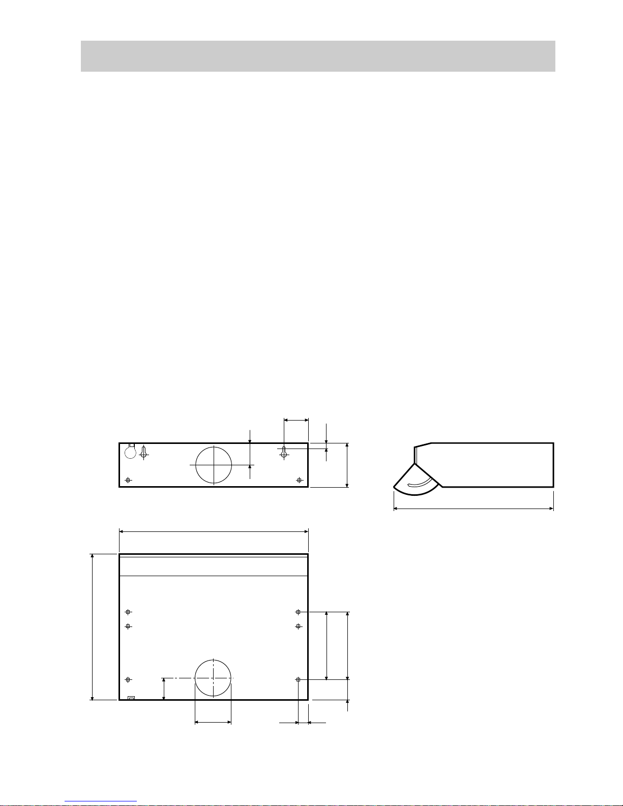
Technical data
Model EFT 500
Capacity Max 170 m3/h x) 118 m3/h
Min. 108 m
3
/h
Dimension Height 150 mm
Width 499 mm
Depth 490 mm
Light 1 x 40 W E 14
Grease filter 1 pc
Mains Voltage 230 V
Electric safety class Class 1
Power rating total 160 W
x)
Valid when the hood is used with carbon filter (recirculation)
560
72
499
99
80
490
195
225
65
37
150
14
64
Ø 120
Page 10

26
1007 AFD L 657 Ed. 11/95
Electrolux AB
Lilla Essingen
S-105 45 Stockholm
konsumentkontakt: 020 - 787750
Oy Electrolux Kotitalouskoneet Ab
ELECTROLUX
Teollisuuskatu 1A
00510 Helsinki
Puh. (90) 396 11
 Loading...