

Page 1
EVEP916
EFEP956
EFEP916
Installation & User manual90cm Cooker
Enjoy peace of mind.
Register your appliance today.
Stay updated on better living services, safety notices and shop
for accessories.
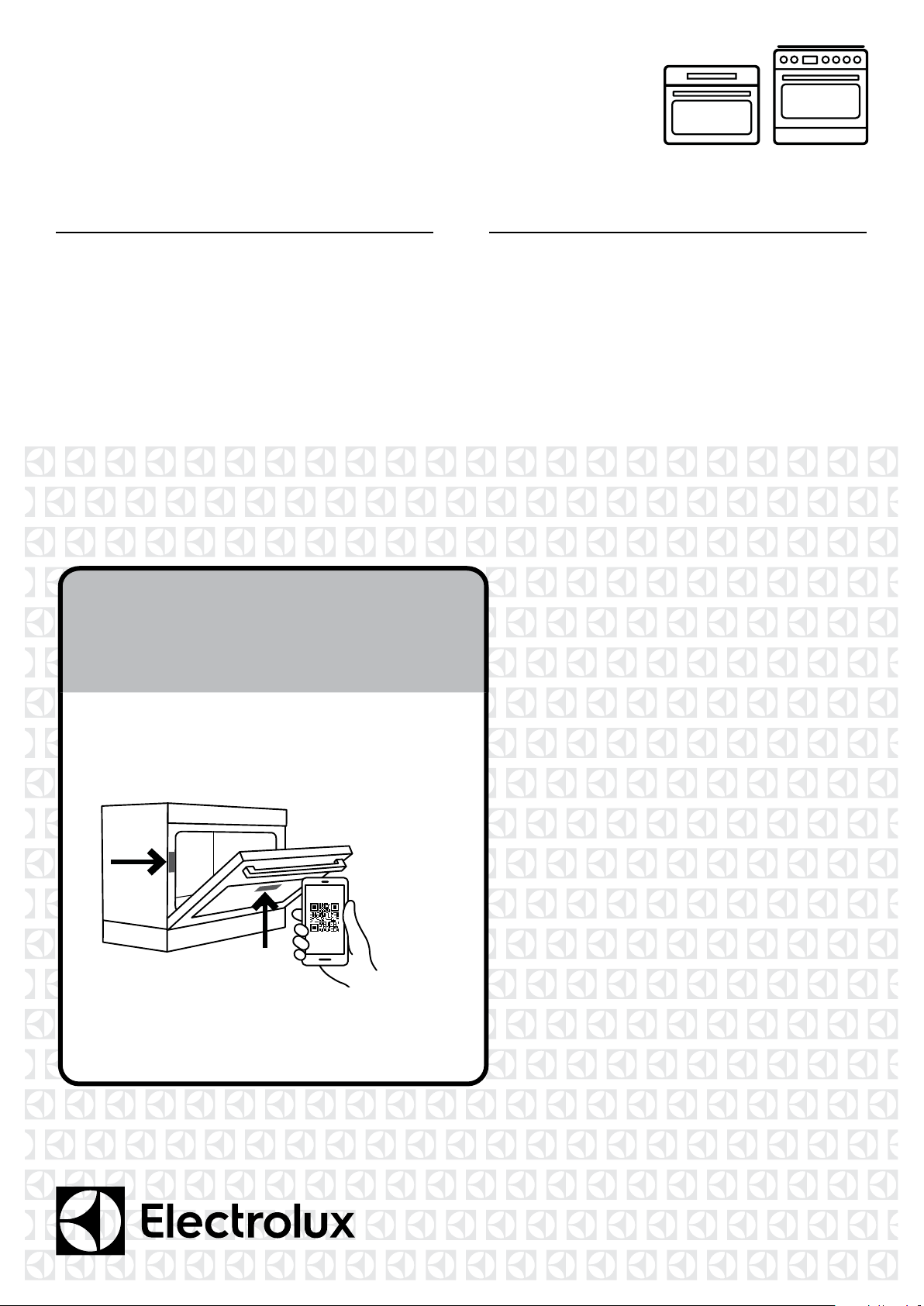
1. Open the camera app on your smartphone and
point at the QR code to scan
Product Registration QR code is located on the
front of your appliance or inside the door rim*.
2. Tap the notification or link to open the registration form
3. Complete your details and enjoy peace of mind
*Exact location of QR code may vary depending on oven model
Page 2

2 electrolux.com.au
CONGRATULATIONS
Thank you for purchasing an Electrolux cooker.
You’ve chosen a product that brings with it decades
of professional experience and innovation. Ingenious
and stylish, it has been designed with you in mind.
So whenever you use it, you can be safe in the
knowledge that you’ll get great results every time.
Welcome to Electrolux.
BEFORE USING YOUR APPLIANCE
Check for any damage or marks. If you find the appliance
damaged or marked you must report it within 7 days to
claim for damages under the manufacturers warranty.
Before you use the appliance, we recommend that you
read through the whole user manual which provides the
description of the product and its functions.
To avoid the risks that are always present when you use a
gas appliance, it is important that the product is installed
correctly and that you read the safety instructions carefully
to avoid misuse and hazards.
For future reference, please store this booklet in a
safe place.
This appliance complies with the requirements of
Australian Standard AS/NZS 60335.2.6.
CONDITIONS OF USE
This appliance is intended to be used in household
and similar applications such as:
• Staff kitchen areas in shops, offices and
other working environments
• Farm houses
• By clients in hotel/motel rooms and other
residential type environments
• Bed and breakfast type environments
BEFORE YOU CALL
CONTENTS
General warnings .....................................................3
Important safety instructions ....................................4
Installation of EFEP916 & EFEP956 .........................5
Installation of EVEP916 ..........................................15
Cabinet construction for built in oven ....................16
Wiring requirements ...............................................17
Electrical and gas connections ..............................18
LPG conversion for EFEP916 .................................19
Testing the operation of the gas cooker .................20
Before using your appliance ...................................21
Before using your appliance – gas hob model .......23
EVEP916 description ..............................................24
EFEP956 description ..............................................25
EFEP916 description ..............................................26
Using the oven .......................................................27
Steam assisted cooking .........................................32
Using the food sensor/probe..................................33
Oven cooking functions .........................................36
Menu ......................................................................39
Oven baking guide .................................................41
Oven cooking guide ...............................................44
Dealing with cooking problems ..............................46
Oven cooking tips ..................................................47
Oven troubleshooting .............................................48
Using the induction hob .........................................49
Induction hob troubleshooting ...............................55
Using the gas hob ..................................................57
Gas hob troubleshooting ........................................58
Cleaning your appliance .........................................59
Cleaning your appliance with pyrolytic cleaning ....61
Cleaning the oven door ..........................................63
Notes ......................................................................65
Warranty .................................................................67
Please ensure you read the instruction manual fully before
you call for service, or a full service fee could be applicable.
RECORD MODEL AND SERIAL
NUMBER HERE:
Model number: ____________________________________
Serial number: _____________________________________
IMPORTANT INFORMATION THAT MAY IMPACT
YOUR MANUFACTURER’S WARRANTY
Adherence to the directions for use in this manual is
extremely important for health and safety. Failure to strictly
adhere to the requirements in this manual may result in
personal injury, property damage and affect your ability
to make a claim under the Electrolux manufacturer’s
warranty provided with your product. Products must
be used, installed and operated in accordance with this
manual. You may not be able to claim on the Electrolux
manufacturer’s warranty in the event that your product
fault is due to failure to adhere this manual.
Page 3

GENERAL WARNINGS
3
Please read this user manual carefully and store in a
handy place for later reference. Pass the user manual
on to possible new owners of the appliance.
Read the following carefully to avoid damage or injury.
NOTE: You must read these warnings carefully
before installing or using the appliance. If you need
assistance, contact your Customer Care Department.
The manufacturer will not accept liability, should these
instructions or any other safety instructions incorporated
in this user manual be ignored.
SYMBOLS
WARNING!
This symbol indicates information concerning
your personal safety.
CAUTION!
This symbol indicates information on how to
avoid damaging the appliance.
product be inspected every 5 years by an authorised
service person.
• Do not install an aftermarket lid or cover over
this appliance.
• The appliance must be earthed.
• Switch the appliance off at the isolation switch
before attempting to change the light globe.
• The cooking process must be supervised.
A short term cooking process must be supervised
continuously.
CAUTION!
Read the following carefully to avoid an electric
shock or fire.
It is important to use your appliance safely. Check these
safety points before using your appliance.
Installation, cleaning and servicing
• An authorised person must install this appliance.
(Certificate of Compliance to be retained).
• Before using the appliance, ensure that all packing
materials are removed from the appliance.
IMPORTANT!
This symbol indicates tips and information
about use of the appliance.
ENVIRONMENT!
This symbol indicates tips and information about
economical and ecological use of the appliance.
WARNING!
• This appliance must not be used as a space heater.
• In order to avoid fire, the appliance must be kept clean
and vents kept unobstructed.
• Do not spray aerosols in the vicinity of this appliance
whilst it is in operation.
• Do not use or store flammable materials in this
appliance storage compartment or near this appliance.
• Do not line the bottom of the oven with foil or
cookware.
• Always use gloves when handling hot items inside
the oven.
• Always turn the grill off immediately after use as fat
left behind may catch fire.
• Do not hang any objects from the hob as it may
block the air vents.
• Do not modify this appliance.
• In order to avoid any potential hazard, the enclosed
installation instructions must be followed.
• Ensure that all specified vents, openings and
airspaces are not blocked.
• Where the appliance is built into a cabinet, the cabinet
material must be capable of withstanding 85°C.
• Only authorised personnel should carry out servicing.
(Certificate of Compliance to be retained).
• Always ensure the appliance is switched off before
cleaning or replacing parts.
• Do not use steam cleaners, as this may cause
moisture build up.
• Always clean the appliance immediately after any
food spillage.
• This appliance must be earthed.
• Due to the weight (freestanding 95-100kg, built in
70kg) and size of cookers, 2 persons are required to
manually manoeuvre them. Remove loose items such
as trivets, oven racks and trays to minimise weight.
• Do not use the oven door handle to lift the cooker,
instead open the oven door and lift the roof of the
oven cavity.
• Take care when lifting to avoid any sharp edges not
intended for lifting.
• Disconnection in the fixed wiring must occur in
accordance with the AS/NZS3000 wiring rules.
• To maintain safe operation, it is recommended that the
Page 4

4 electrolux.com.au
IMPORTANT SAFETY INSTRUCTIONS
INFORMATION ON DISPOSAL
FOR USERS
ENVIRONMENT!
• Most of the packaging materials are recyclable.
Please dispose of these materials through your local
recycling depot or by placing them in appropriate
collection containers.
• If you wish to discard this product, please contact
your local authorities and ask for the correct method
of disposal.
WARNING!
OVEN
• During use the appliance becomes hot. Care should
be taken to avoid touching the hot surfaces inside
the oven.
• Always use gloves when handling hot items inside
the oven.
• Switch the appliance off before removing the oven
light glass for globe replacement.
• To avoid an accident, ensure that oven shelves and
fittings are always inserted into the appliance in
accordance with the instructions.
• Do not use the door as a shelf.
• Do not push down on the open oven door.
• Do not cover the grill insert with foil, as fat left there
may catch fire.
• Always keep the grill dish clean as any fat there may
catch fire.
• Always turn the grill off immediately after use, as fat left
there may catch fire.
• Do not leave the grill on unattended.
• To avoid a fire, ensure the grill tray and fittings are
always inserted into the appliance in accordance with
the instructions.
GAS HOB MODEL
• Do not allow pots to boil dry, as damage to both pan
and hob may result.
• Do not operate the cooktop for an extended period of
time without a pot or pan on the burner.
• Do not allow large cookware to overhang the hob onto
the adjacent benchtop. This will cause scorching to
the benchtop surface.
• Ensure burner bodies and trivets are properly located.
• Unattended cooking with oil or fat on a hob can
be dangerous and result in fire.
• In order to avoid a fire do not store items on the
cooking surface.
INDUCTION HOB MODEL
• In order to avoid a fire do not store items on the
cooking surface.
• Do not place heat resistant mats, wire mats or
aluminium foil under pots and pans.
• Do not allow pots to boil dry, as damage to both pan
and hob may result.
• Do not use the hob as extra bench space or as a
cutting board.
• Do not allow large cookware to overhang the hob onto
the adjacent benchtop. This will cause scorching to
the benchtop surface.
• Do not slide pans across the surface of the ceramic
glass as it could result in scratching of the surface.
• The induction hob is not intended to be operated
by means of an external timer or separate remotecontrol system.
• Use only induction specific cookware.
• If the hob surface is cracked, switched off the
appliance to avoid the possibility of electric shock.
• Metallic objects such as knives, forks, spoons and lids
should not be placed on the hob surface since they
can get hot.
• After use, switch off the hob element by its control and
do not rely on automatic switch off.
• Unattended cooking with oil or fat on a hob can
be dangerous and result in fire.
• The appliance is not intended to be operated by
means of an external timer or remote control system.
• Users with an implanted pacemaker must keep their
upper body minimum 30cm from induction cooking
zones that are switched on.
WARNING!
CHILD SAFETY
• This appliance is not intended for use by persons
(including children) with reduced physical, sensory
or mental capabilities, or lack of experience and
knowledge, unless they have been given supervision or
instruction concerning use of the appliance by a person
responsible for their safety.
• Children should be supervised to ensure that they do not
play with the appliance.
• During use this appliance becomes hot. Care should
be taken to avoid touching hot surfaces, eg. Oven door,
heating elements, hobs or trivets.
• Accessible parts will also become hot when in
use. To avoid burns and scalds children should
be kept away.
• Always turn pan handles to the side or rear to prevent
accidental knocking and to keep out of reach of children.
Page 5
INSTALLATION OF EFEP916 & EFEP956
5
Cabinet requirement
Models EFEP916 & EFEP956 are designed to fit into a
900mm wide gap between standard kitchen cabinets. The
appliance integrates with the kitchen cabinets by matching
the height, depth and kick panel. The cooker may also
be installed at the end of a line of benches or with a free
space either side. In addition, a slot-in type installation is
catered for allowing a continuous cabinetry kick panel to
be used.
WARNING!
• The cooker must be installed and serviced only by
an authorised person.
• A Certificate of Compliance MUST be supplied to
be kept by the customer.
• The packing materials must be removed before
you install the cooker.
• The surrounding kitchen cabinets must be able
to withstand 85°C. Electrolux WILL NOT accept
responsibility for damage caused by installation into
kitchen cabinets which cannot withstand 85°C.
• The pipes used for installation MUST have sufficient
loops so the cooker can be moved for service (gas
models).
• The vents, openings and air spaces MUST NOT
be blocked.
• Two anti-tilt brackets are supplied and stored in the
base of the packaging
• Clearances to combustible surfaces may be reduced
if combustible surfaces are protected in accordance
with clause 6.10.1.2 of AS/NZS 5601.1, or clause 6.9.2
of AS/NZS 5601.2.
• When setting the cooker height, ensure the top of the
cooker is at least 10mm higher than the level of the
benchtop.
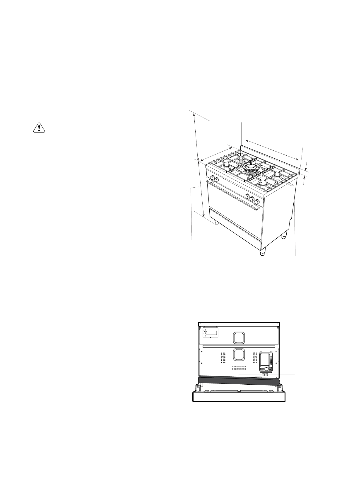
Dimensions
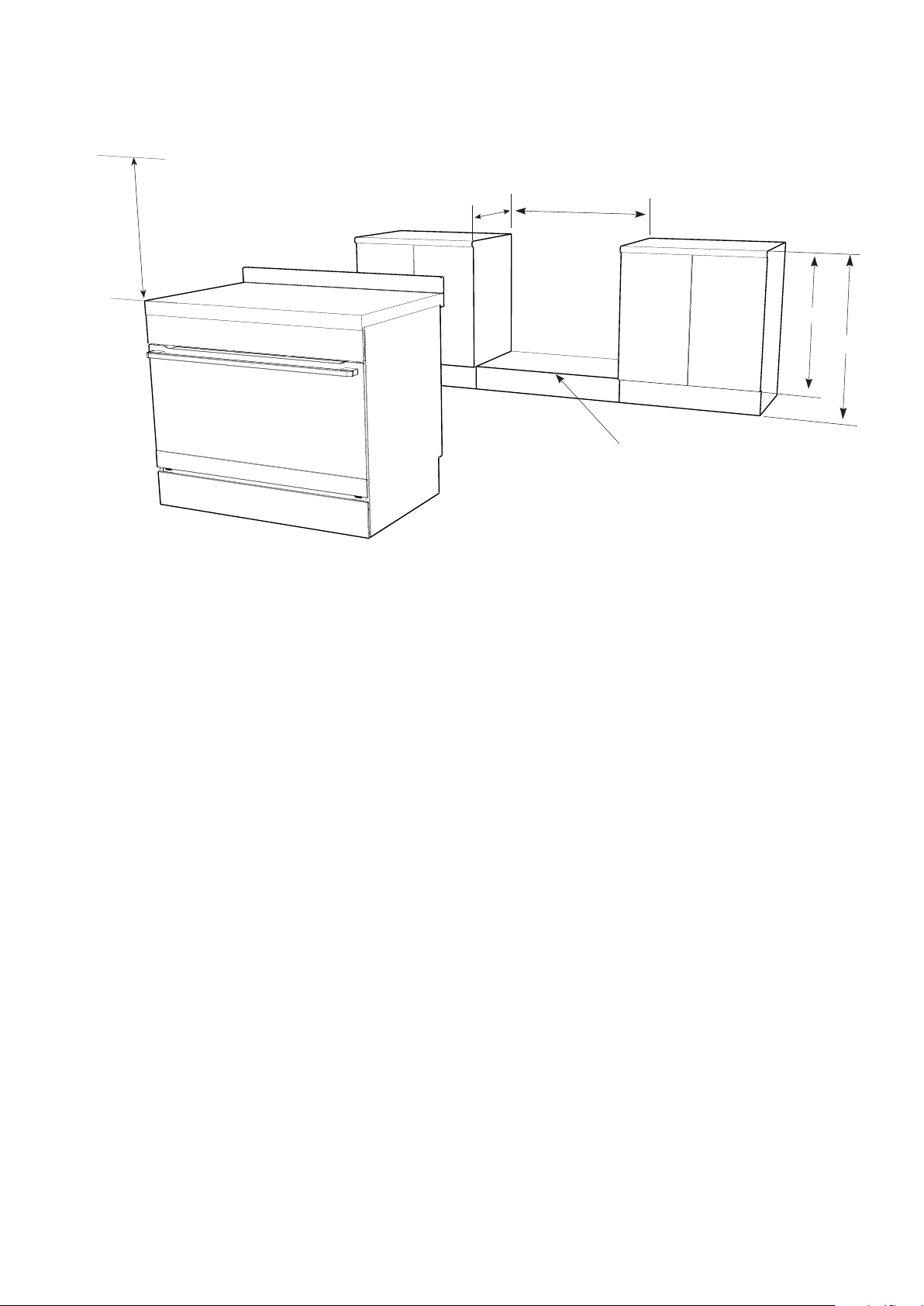
600mm minimum
vertical clearance from
combustible surfaces
600mm
Gas hob 910mm
(adjustable 910 - 930mm)
Ceramic hob 906mm
(adjustable 906 - 926mm)
895mm
60mm
15mm
(height of trivet above hob)
• The anti-tilt brackets and chain or front stops MUST
be installed to avoid accidental tipping (freestanding
and slot-in models).
• You MUST NOT lift or pull the cooker by the door
handle.
• The cooker MUST be checked every five years.
• If the supply cord is damaged, it must be replaced
by the manufacturer, its service agent or similarly
qualified persons in order to avoid a hazard.
• The appliance must not be installed behind a
decorative door in order to avoid overheating.
• Due to the weight (95-100kg) and size of the cooker,
2 persons are required to install it.
Gas model clearance requirements
• Ensure the appliance is installed in accordance
with clauses 6.2.5 and 6.10.1.1 of AS/NZS 5601.1
or clauses 6.9.1 and 6.9.5 of AS/NZS 5601.2 with
regard to clearances to combustible surfaces and
materials, and clearances to rangehoods and exhaust
fans, to ensure clearances of 200mm from burners to
vertical combustible surfaces observe the minimum
dimension of 100mm from each side of the cooker to
combustible surfaces.
Splashback
The splashback is secured to the back of the cooker.
REMOVE the splashback before installing the feet.
Undo this
screw to remove
the splashback.
Re-attach the
screw afterwards
Page 6
6 electrolux.com.au
INSTALLATION OF EFEP916 & EFEP956 (CONTINUED)
Freestanding installation
The freestanding type installation requires four screwin feet to be installed before it can be fitted in between
cabinets, with cabinets on one side or without adjacent
cabinets. There is no clearance requirement to adjacent
side cabinets.
To ensure cooker’s stability, the anti-tilt brackets must
be installed.
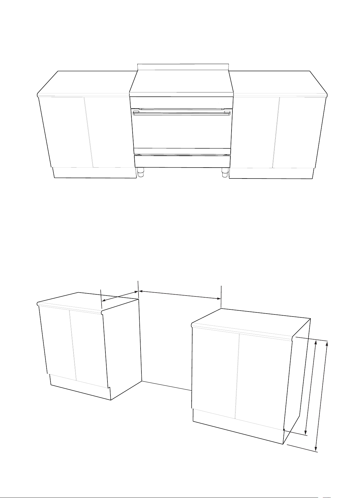
Cabinet construction for freestanding installation
600mm
both sides
900mm minimum
Four screw-in feets are supplied with the appliance and
can be found in the accessories pack in the oven.
Freestanding models are supplied with a clip-on kick panel.
755mm NOM
00mm NO
9
M
Page 7
Installation of screw-in feet
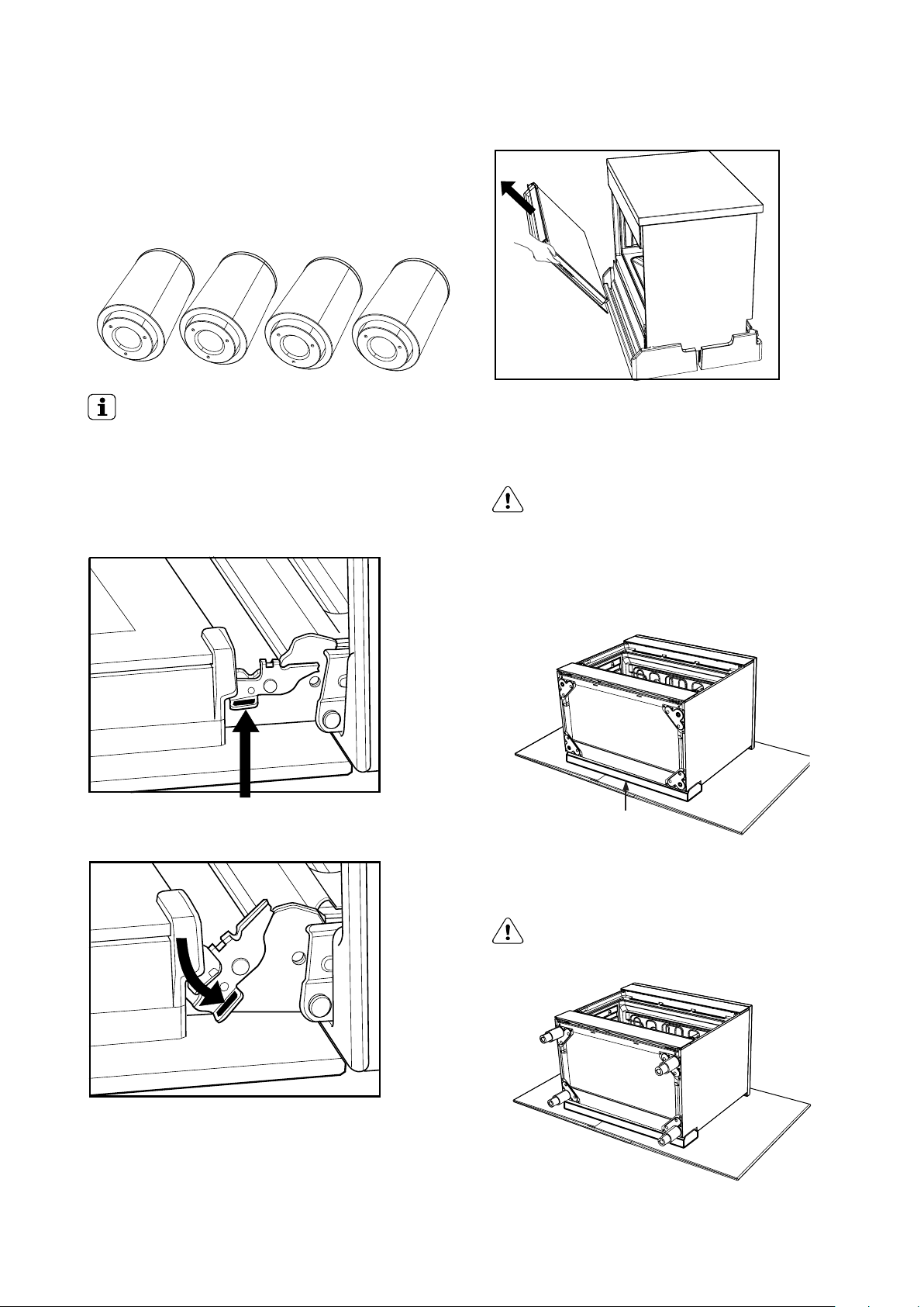
Locking tab up at normal position.
Freestanding appliance are supplied with four screw-in
feet in the internal accessory pack. The screw-in feet
can be adusted by turning the lower half clockwise or
anti-clockwise.
7
IMPORTANT!
• If the appliance is a gas hob model, remove the
burner cap and burner crown. Store all items safely,
away from the installation area.
You MUST remove the oven door and the accessory pack
before commencing installation
Locking tab up at normal position
Gently close the door until it comes to a stop. Then lift the
door off the hinge.
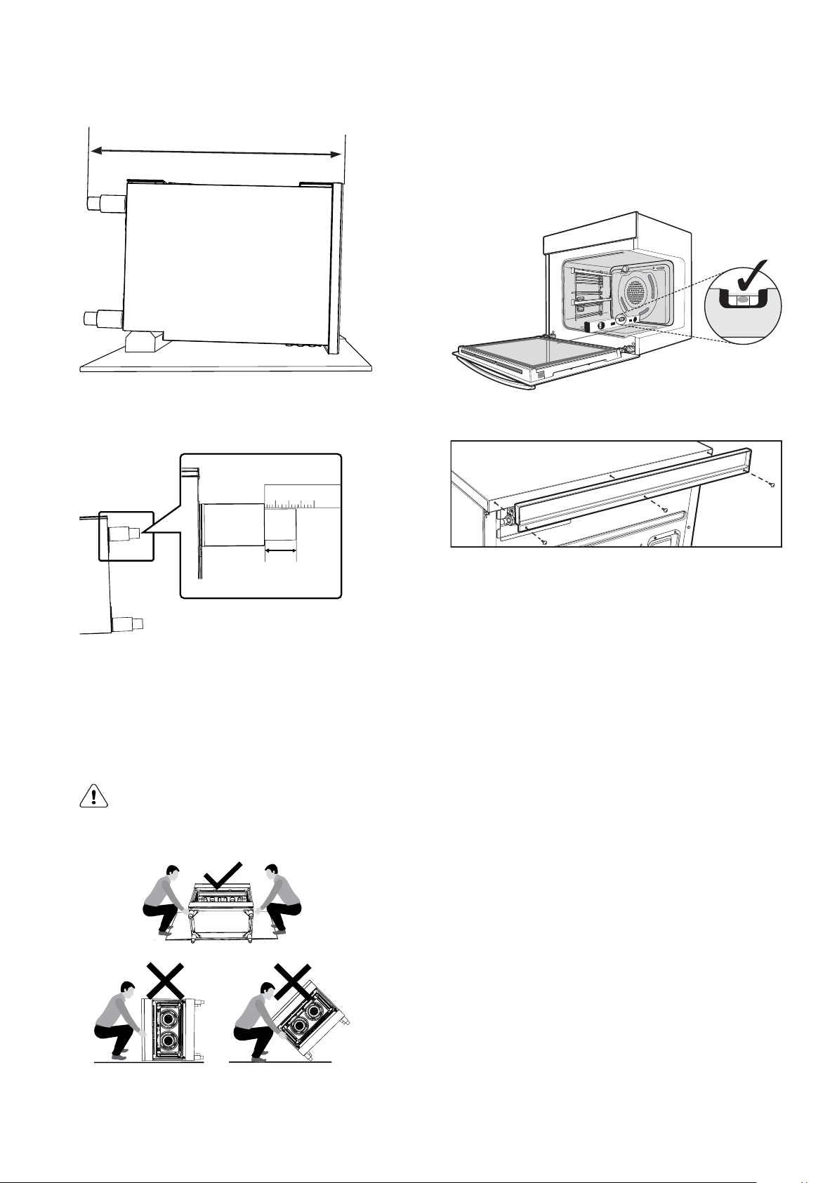
Tilt and carefully lay the appliance on its back to gain
access to the installation point for the screw in feet.
CAUTION
• To avoid scratching the floor and the appliance it
self, fold the packaging carton board and place it
underneath the appliance as protection.
• The cooker MUST be laid on its back when installing
the feet.
Put the oven door handle protection foam
underneath the laid down cooker to protect
your cooker when puting it upright
Press the locking tab down for removing the door.
Install the four supplied feet via the four installation points.
Make sure that each foot is securely fastened.
CAUTION
• Do not over-torque the foot.
Adjust the height of the screw-in feet to make sure the
hob surface is 10mm above the bench when appliance
is upright.
Page 8
8 electrolux.com.au
For a 900mm height kitchen bench top, adjust the
lower half of the feet to measure 50mm as shown
in the illustration.
50mm
INSTALLATION OF EFEP916 & EFEP956 (CONTINUED)
Bench height + 10mm minimum
If your kitchen has a 900mm height bench top, follow the
quick measurement guide below before putting the cooker
upright.
Levelling oven
Place a level in the oven as below making sure the level sits
on the front and rear forms. Adjust the feet accordingly to
level the appliance.
Installing splashback
Tilt the appliance upright by lifting the back of the hob and
pivoting it about the back two feet.
WARNING
Heavy item!
This step must be performed by two persons.
Fit splashback to rear of hob with three screws provided.
Page 9
Installing the anti-tilt brackets
To ensure cooker stability, the anti-tilt brackets must be
installed.
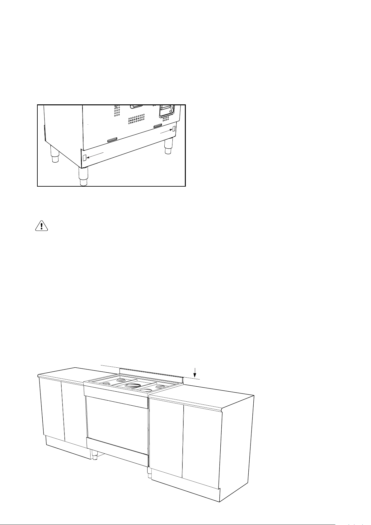
There are left and right engagement slots for the anti-tilt
bracket at the bottom rear of the appliance.
Anti-tilt bracket engagement slots
The following steps must be followed to ensure the correct
installation of anti-tilt brackets and the stability of the
appliances.
9
CAUTION
It is not recommended to push and pull the appliance on
uneven or rough surface. Use other means to maneuver the
appliance if necessary.
1 Carefully push the appliance into the cabinet
cavity until the back of the oven is flush against
the back wall.
2 Use non-permanent methods to mark a line on the
wall along the top surface of the splashback. This
line is used as a reference line to locate the correct
location of where the anti-tilt brackets need to be
installed.
3 After the reference line is marked, pull the appliance
out of the cabinet cavity to install the anti-tilt brackets.
Anti-tilt bracket
installation
reference line
Page 10
10 electrolux.com.au
INSTALLATION OF EFEP916 & EFEP956 (CONTINUED)
WARNING
Appropriate fasteners must be used to suit the
type of wall on which the anti-tilt brackets are
installed.
• Freestanding unit must be pushed up against
the wall on installation. On gas units check
that the gas hose, if used, has not been
kinked during installation.
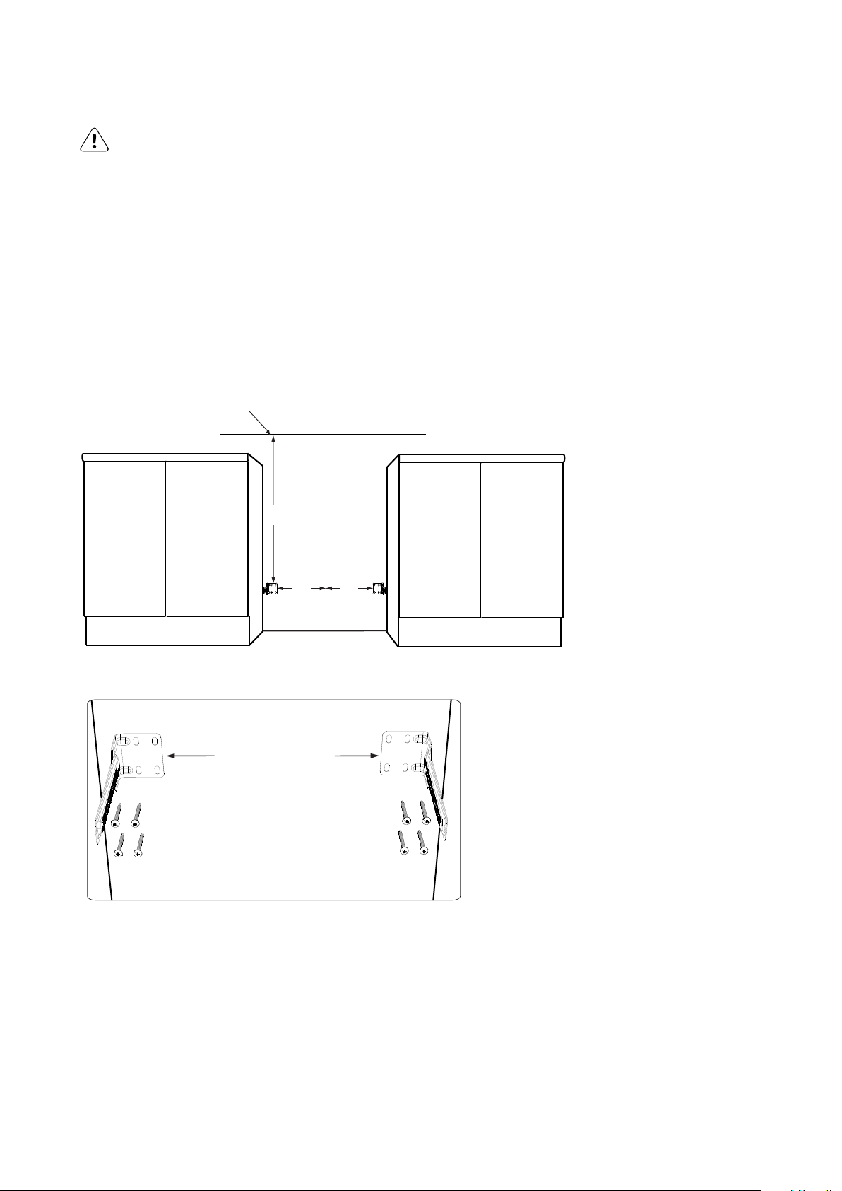
4 The anti-tilt brackets must be secured to the
rear wall of the cavity with appropriate fastener
according to dimensions in diagram.
Anti-tilt bracket
installation reference line
C
L
725
370
Install anti-tilt brackets
in this orientation as
shown.
(Fasteners not supplied)
370
Connect services to the appliance prior to placing
in to cavity.
To locate appliance, slide into cavity ensuring the antitilt brackets fully engaged with the rear left and right
engagement slots.
The unit must be pushed against the wall on installation.
Re-install oven door, burner body, burner caps and trivets
after the appliance is placed in the cavity.
Gas only: Check that the gas hose, if used, has not been
kinked during installation.
Page 11

Installing the clip-on kick panel
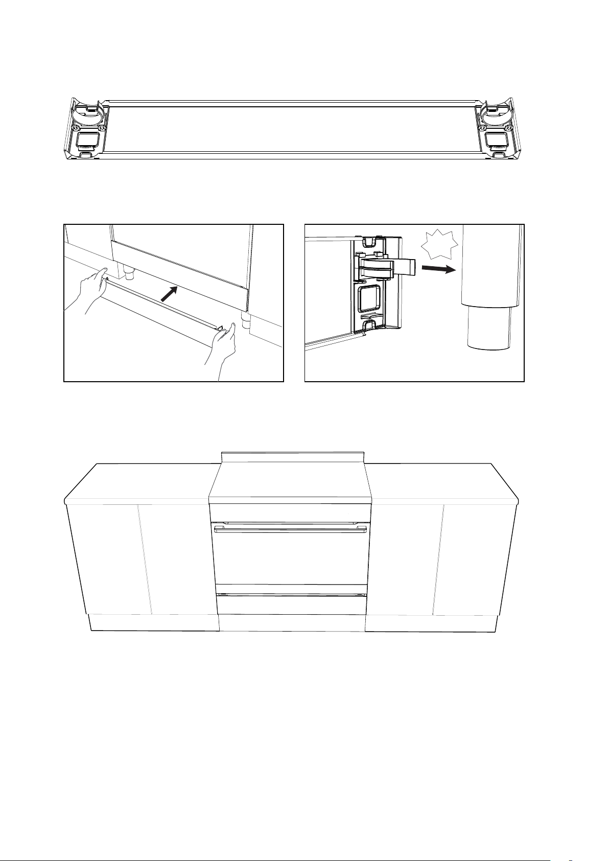
Freestanding models are supplied with a clip-on kick panel
that can be assembled to clip onto the front feet for a more
integrated and seamless kitchen appearance.
Clip base
Clip snap
1 Assemble the clip snap onto the base.
11
2 Press in both assembled clip modules into the kick
panel in the orientation as shown below.
click!
click!
3 Make sure both clip modules are in the same
orientation after installation.
Page 12
12 electrolux.com.au
INSTALLATION OF EFEP916 & EFEP956 (CONTINUED)
4 Clip the kick panel onto the front feet of the
appliance. Make sure the kick panel snaps onto the
larger section of the front feet.
snap!
Slot-in installation
The slot-in type installation use the appliance as supplied.
The appliance can be mounted on a plinth. This enables
a continous cupboard kickboard to be installed, giving
a more intergrated appearance. There is no clearance
requirement between oven and adjacent side cabinets.
Page 13
600mm minimum
vertical clearance
from combustible
surfaces
600mm
900mm
minimum
This surface to be level with the top edge
of the kick board
13
755mm
900mm
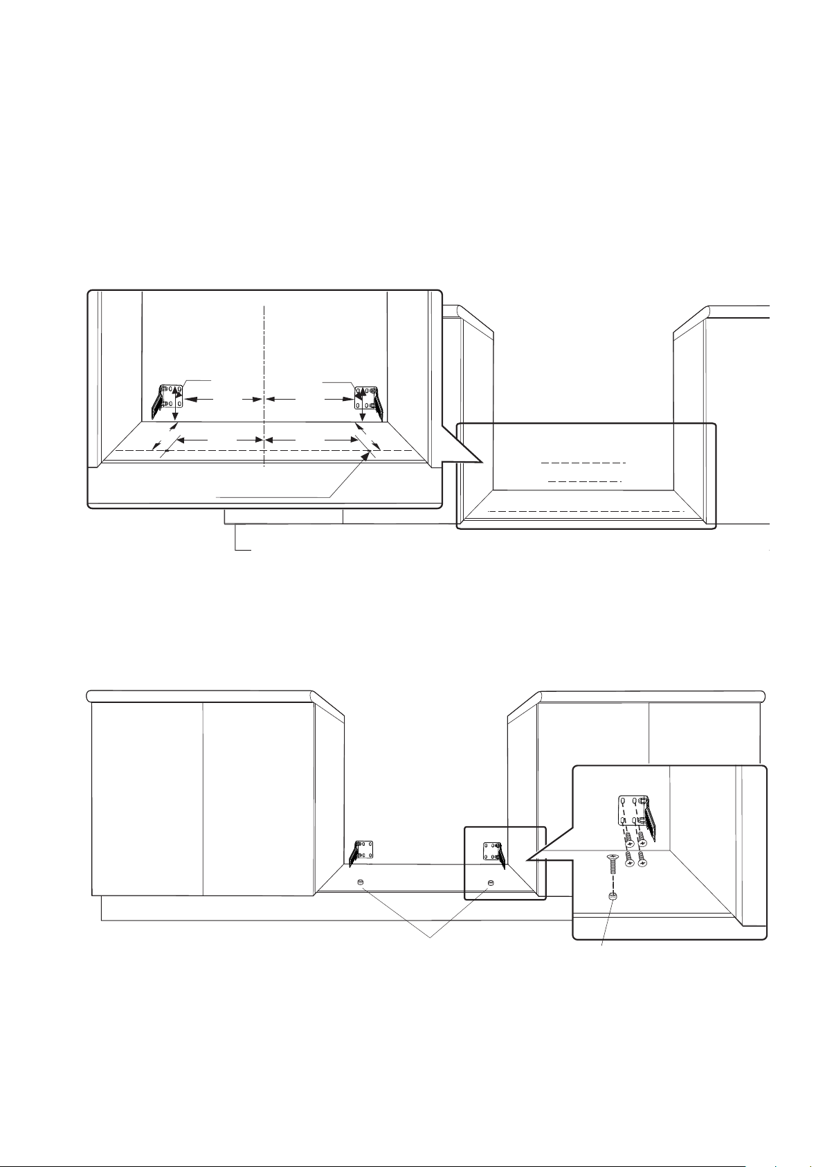
The anti-tilt brackets are to be secured to the back wall
with appropriate fasteners.
Two stops are to be screwed to the plinth in locations as
shown (stops provided). The stops locate into slots in the
base of the appliance to prevent the product from being
pulled forward when installed.
Measurements from the rear wall are to be adjusted if there
are tiles etc. that come between the appliance and the wall.
Once services are connected, product can be lifted
onto the plinth and pushed back carefully, ensuring the
appliance engages into both brackets at the rear and
the front stops.
If the product requires removal for service, it must be lifted
at the front approximately 5mm to clear the front stops
prior to being pulled forward.
Page 14
14 electrolux.com.au
INSTALLATION OF EFEP916 & EFEP956 (CONTINUED)
C
L
104
370 370
165 165
Location of holes for front stops
344
Measurements are to be adjusted to account for the thickness of any skirting
board or tiles coming between the back of the appliance and the wall
344
104
+
+
+
+
+
+
+
+
+
+
Front stops
Front stops
Page 15
INSTALLATION OF EVEP916
15
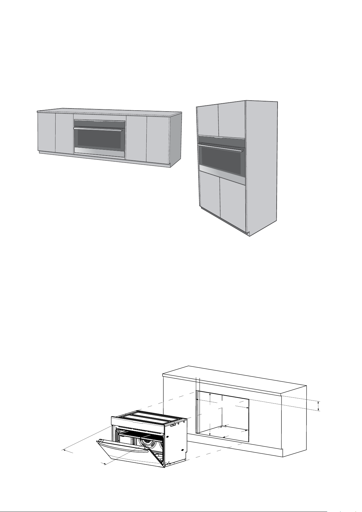
Underbench installation
Your underbench oven looks best when the control panel
is directly under the benchtop. An upper infill panel may
be added if the cooktop placed above the benchtop is
too deep. *Refer to cooktop installation instructions for
required clearance between cooktop and oven.
Vertical cabinet installation
The oven can be built into a vertical cabinet in the same
manner as an underbench. The required cavity dimensions
are the same and the product is secured to the cabinet in
the same way.
For the best integration within a kitchen, install this
appliance in a cupboard that gives a flush fit with the
surrounding cupboard fronts. A recess of 20mm is ideal.
NOTE: Your appliance must be mounted on a horizontal
surface for the full width and depth of the product.
NOTE: A ventilation slot 20mm wide is required at the
rear of the base of the cabinet floor.
The cooker MUST be installed in compliance with:
• Wiring connections in AS/NZS 3000 Wiring Rules.
• Local regulations, municipal building codes and
other statutory regulations.
100mm
max
900mm
600mm
20mm
slot
*20mm
see note
below
876mm
Mounting holes
NOTE: If a powerpoint is fitted it must be accessible with the
appliance installed.
580mm
*Refer to cooktop installation instructions for required
clearance between cooktop and oven.
Page 16
16 electrolux.com.au
CABINET CONSTRUCTION FOR BUILT IN OVEN
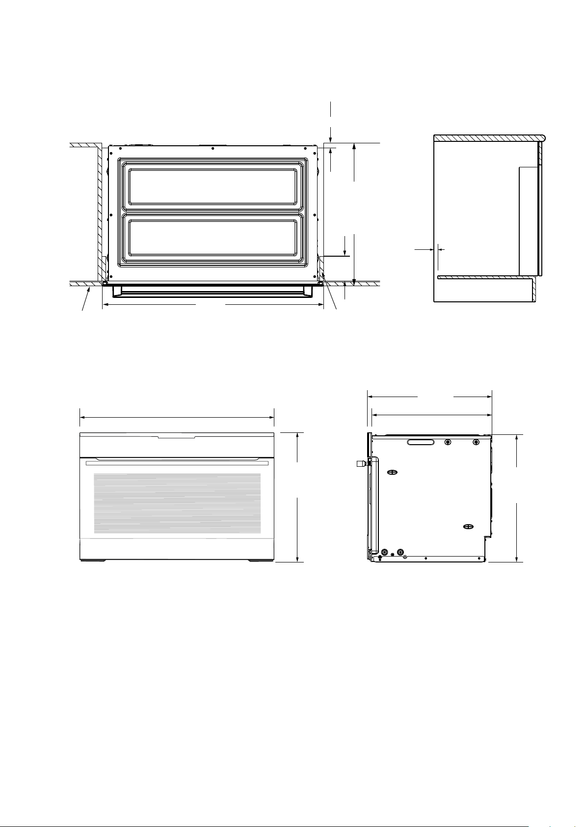
20mm
580mm minimum
20mm
100mm
max.
(see NOTE)
cupboard
door
Oven dimensions
895mm
900mm
596mm
Infill panel
16mm thickness
572mm
552mm
586mm
Page 17
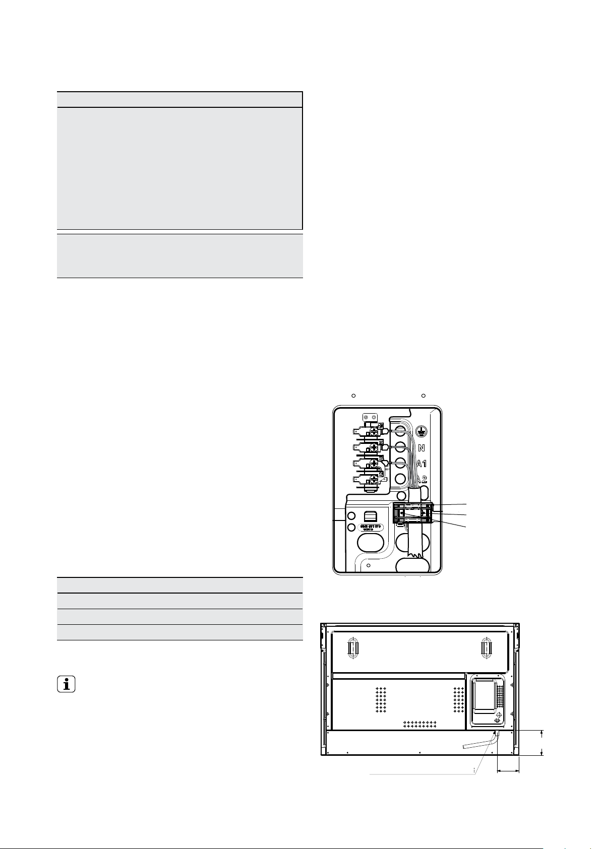
WIRING REQUIREMENTS
17
For New Zealand Only:
The cooking range must be connected to the supply
by a supply cord fitted with the appropriately rated
plug. This plug is to be compatible with the socketoutlet fitted to the final sub-circuit in the fixed wiring
that is intended to supply this cooking range.
Supply cord size required:
EVEP916, EFEP916 – 4mm
EFEP956 – 10mm
2
2
Data plate gives information about rating
is located behind the bottom
of the oven door
• A functional switch MUST be provided near
the appliance in an accessible position
(AS/NZS 3000 - Clause 4.7.1).
• Wiring MUST be protected against mechanical
failure (AS/NZS 3000 - Clause 3.9).
• This cooker requires a means of disconnection
incorporated into the fixed wiring.
• The cooker MUST be properly earthed.
Connecting to services and commissioning
This appliance must be installed by an authorised
person, according to all codes and regulations of:
• Electrical supply authorities.
• Building regulations.
• Local government and council authorities.
• AS/NZS5601.1 (particular attention to 6.10.1
and figure 6.3, and clause 6.10.1.11).
• AS/NZS 3000 (particular attention to clause
4.7.1 and clause 3.9).
Hard wiring detail
1 Remove terminal cover plate from rear panel
of appliance.
2 Fit wires through hole in cover plate and
make connections to terminals.
3 Engage wires into plastic clip. Secure plastic
clip with two long silver screws (supplied in
separate bag).
4 Replace cover plate onto rear panel.
• This range must be connected with cable of
75°C rating minimum.
• This product has passed the insulation resistance test
after manufacture. If the resistance reading is low at
installation, it is probably caused by moisture from the
atmosphere being absorbed by the elements after the
range has been produced. (Pass at 0.01 MΩ AS/NZS
3000 Wiring Rules Clause 8.3.6.2).
Note: When connections are made to a multi-phase
230/240V supply, the bridge piece MUST be removed
from between the active connections.
Rated Power Input
Model Total kW A1 kW A2 kW
EFEP956 9.6* 5.2 9.5
EFEP916 5.2 5.2 0
EVEP916 5.2 5.2 0
*power sharing between hob and oven
IMPORTANT!
Before you cook in your new oven it is important
that the protective oils used in the manufacture
of the product be removed.
• Make sure that the room is well ventilated (to allow
smoke to escape).
• Then run the oven on 180°C for 30 minutes.
Plastic clips
Plastic clip
Securing points
Electrical connection location - Model EVEP916
113
Entry point of electrical cable
99
Page 18
18 electrolux.com.au
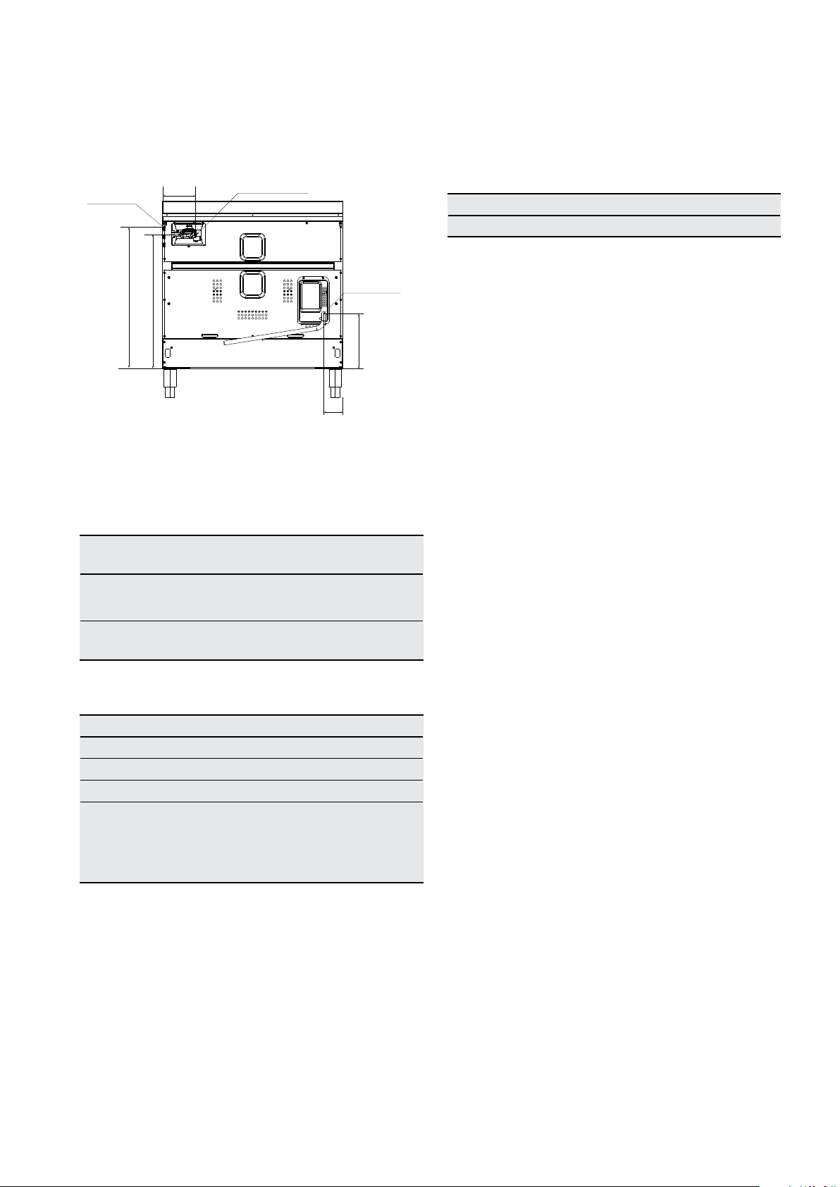
ELECTRICAL & GAS CONNECTIONS
Models EFEP916, EFEP956
Gas connection
Gas hose restraints
point to regular
models: EFEP916,
696
168
673
point to regulator
Models: EFEP916,
95
Electrical cable
entry point
Models:
EFEP916,
EFEP956,
278
Installing the gas cooker
Gas pressures
The following table shows the supply and operating
pressures for various gases.
Gas type Natural
gas
Supply pressure at inlet
to appliance regulator
Operating pressure at
1.13 ( kP a )
Minimum
1.0 0 (k P a ) 2.60 kPa
Universal
LPG
2.75
kPa
appliance test point
The following table shows the injector sizes for
each burner.
Injector Orifice Natural gas Universal LPG
Low heat burner 1.0 0m m 0.55mm
Medium heat burner 1.35mm 0.70mm
High heat burner 1.6 0m m 0.90mm
Intense heat
dual wok burner
0.92mm
(inner)
0.46mm
(inner)
Checking piping size
To work out a suitable pipe size for connection use the
information in this table:
Model Natural gas Universal LPG
EFEP916 57. 2 M J/ h 49.9 MJ/h
For information and requirements about construction and
capacity of consumer piping refer to AS5601 series of
standards.
Gas connection
Read these points before connecting to the gas supply:
• The appliance is preset for natural gas use. If LPG is
to be used see Conversion to LPG section.
• Gas installation must be made in accordance with
AS5601, the local gas fitting regulations, municipal
codes and other statutory regulations.
• The gas connection point is a ½” BSP external thread
located at the rear of the appliance as shown.
• A regulator is supplied which must be fitted to the
appliance. Ensure that when fitted the pressure test
point of regulator is accessible.
• The regulator is to be fitted to the manifold inlet at
the rear of the appliance and the connection thread
is sealed using a tape or jointing compound suitable
for gas connections. The consumer piping is then
connected to the inlet of the regulator, either:
1 directly, or
2 using a hose assembly and in accordance
with Clause 6.10.1.9 of AS 5601.1 (High level
connection) together with the supplied elbow.
The elbow is fitted to the inlet of the regulator
and oriented to allow the hose to hang
downwards. The connection thread between
the regulator and elbow is sealed using a
tape or jointing compound suitable for gas
connections.
3 x 1.30mm
(Outer)
3 x 0.62mm
(outer)
Page 19
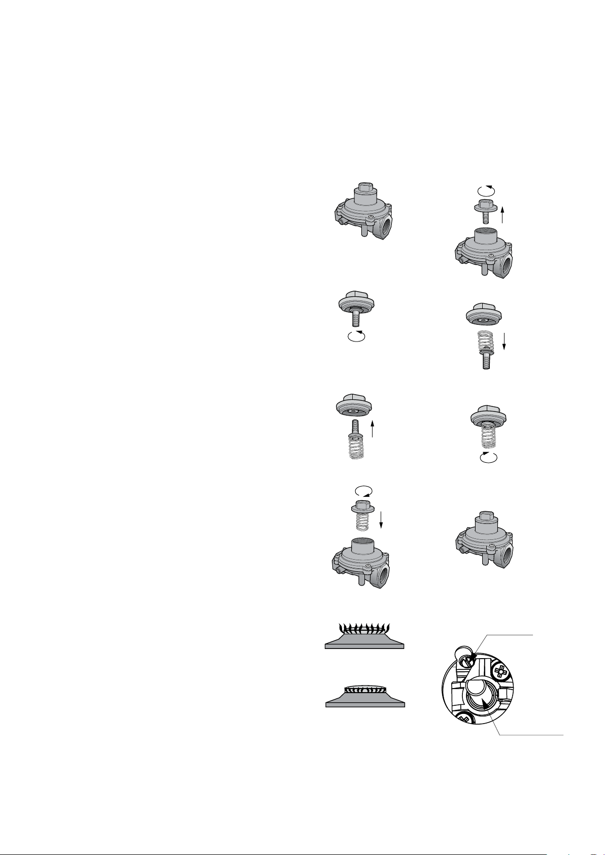
LPG CONVERSION MODEL EFEP916
19
This appliance is supplied set up for Natural Gas usage.
A conversion kit is included with the product for Universal
LPG usage. The conversion kit contains 7 injectors and
1 LPG sticker.
Please follow the procedure below if a conversion to suit
UNIVERSAL LPG is required:
1 Remove the hotplate trivets, burner caps and
burner crowns to access the hotplate injectors.
Replace the factory fitted injectors with the
appropriate injectors, as supplied. Refer to injector
orifice table for injector sizes. The injector size is
stamped on the side of the injector.
2 Unscrew the top hat nut from the regulator. The top
hat nut and control pressure spring assembly will
disengage as an assembly.
3 Unscrew the threaded pin from top hat.
4 Upturn threaded pin, so spring is free and screw
pin back into the top hat until firm.
5 Refit the top hat nut assembly to the regulator
ensuring that it is fully screwed down. The regulator
is now set for connection to LPG.
• Check that the turret screw is fully screwed
down.
• Check that the regulator has been fitted to the
gas supply line in the correct orientation, the
arrow on the base of the body indicates the
direction of gas flow.
A
Top hat nut assembly,
fully screwed down
C
Configuration for
Natural Gas
B
D
Turn top hat nut
anti-clockwise
and remove
6 Turn on the gas supply and at each new
connection check for leaks using soapy water.
Each hotplate valve should be turned on, one at a
time, and the injector hole blanked off for several
seconds.
7 The operation of the regulator can be confirmed by
connecting a manometer to the pressure test point
located on the side of the regulator body adjacent
to the outlet.
With the appliance operating check the outlet
pressure:
• when all burners of the appliance are operating
at maximum,
• when the smallest burner of the appliance is
operating at minimum.
Under these conditions the outlet pressure should
not vary from the nominal outlet pressure of 2.60kPa
by more than ±0.52kPa.
8 If the regulator appears to not be performing
satisfactorily then check the following points:
• If the outlet pressure is consistently too low then
the inlet pressure may be too low and adjustment
of an upstream regulator may be needed, or an
upstream regulator or valve with insufficient flow
capacity may be present in the gas supply line.
If this is suspected then it may be necessary to
repeat the checks whilst measuring both the
inlet and outlet pressure to determine if the inlet
pressure is in the range 2.75 – 7.00kPa.
• Check that the insert has been fitted correctly.
E
G
Flame size adjusted to
maximum
Flame size adjusted to
minimum
F
Configuration for LPG
H
Bypass screw
Control knob shaft
NOTE: The cooker MUST be tested after installation,
before handing over to the customer. You MUST
have a manometer and a connecting tube.
Page 20

20 electrolux.com.au
TESTING THE OPERATION OF THE GAS COOKER
Checking gas supply
1 Check the manometer zero point is correct.
2 Connect the manometer to the cooker pressure
test point. This is located on the regulator.
3 Turn on the gas supply and the electricity and try
to ignite the gas.
NOTE: It will take additional time to light the gas for the
first time as air needs to be purged from the pipes.
4 Check the operating pressure for the particular
gas type.
Checking the function of the regulator
With the appliance operating check the outlet pressure:
• When all burners of the appliance are operating
at maximum,
• When the smallest burner of the appliance is
operating at minimum.
Under these conditions the outlet pressure should not vary
from the nominal outlet pressure by more than ±20% of
the nominal outlet pressure (i.e. ±0.20kPa for Natural Gas).
If the regulator appears to not be performing satisfactorily
then check the following points:
1 If the outlet pressure is consistently too low then the
inlet pressure may be too low and adjustment of an
upstream regulator may be needed, or an upstream
regulator or valve with insufficient flow capacity may
be present in the gas supply line. If this is suspected
then it may be necessary to repeat the checks
whilst measuring both the inlet and outlet pressure
to determine if the inlet pressure is in the range
1.13 – 5kPa.
Testing the cooker features
• Observe the flame appearance on each burner.
If it is much smaller or larger than expected, then
the injector size needs checking.
NOTE: When flame is unsatisfactory, then refer to the
Electrolux Technical Publications and correct the fault,
if possible.
When maximum flame appearance is correct, then check
the turn-down setting on each burner. If the settings
appear to be incorrect, proceed as follows:
1 Adjust the bypass screw mounted on the body of
each hotplate control. This is accessible when the
control knob and the control panel are removed.
2 Check the ignition on all burners both separately
and in combination.
3 Check the operation of the electrical components,
if applicable.
4 If you are satisfied that the cooker is operating
correctly, then turn it off and show the customer
how to use it. Make sure you ask the customer
to operate the clock and controls.
NOTE: If the cooker cannot be adjusted to perform
correctly, then inform the customer of the problem and
put a warning notice on the cooker. If the problem is
dangerous, then disconnect the cooker. If there is a fault,
then the customer should be advised to contact the
manufacturer’s local service organisation or the retailer.
2 Check that the regulator has been fitted to the gas
supply line in the correct orientation, the arrow on the
base of the body indicates the direction of gas flow.
Once these checks have been completed, if the regulator
still fails to perform in a satisfactory manner it should
be replaced.
Page 21
BEFORE USING YOUR APPLIANCE
L = left hand side
R = right hand side
1
2
L = left hand side
R = right hand side
21
Preparing the appliance
1 Please remove all stickers, leaflets and boxes
from the door and from the floor of the oven
before operation.
2 Please wipe out the oven interior prior to operation
with warm soapy water and polish dry with a soft
clean cloth. Do not close the oven door until the
oven is completely dry.
3 Do not line the oven with foil. It will damage
the enamel.
Setting the time
The time of day must be set before the appliance can
operate.
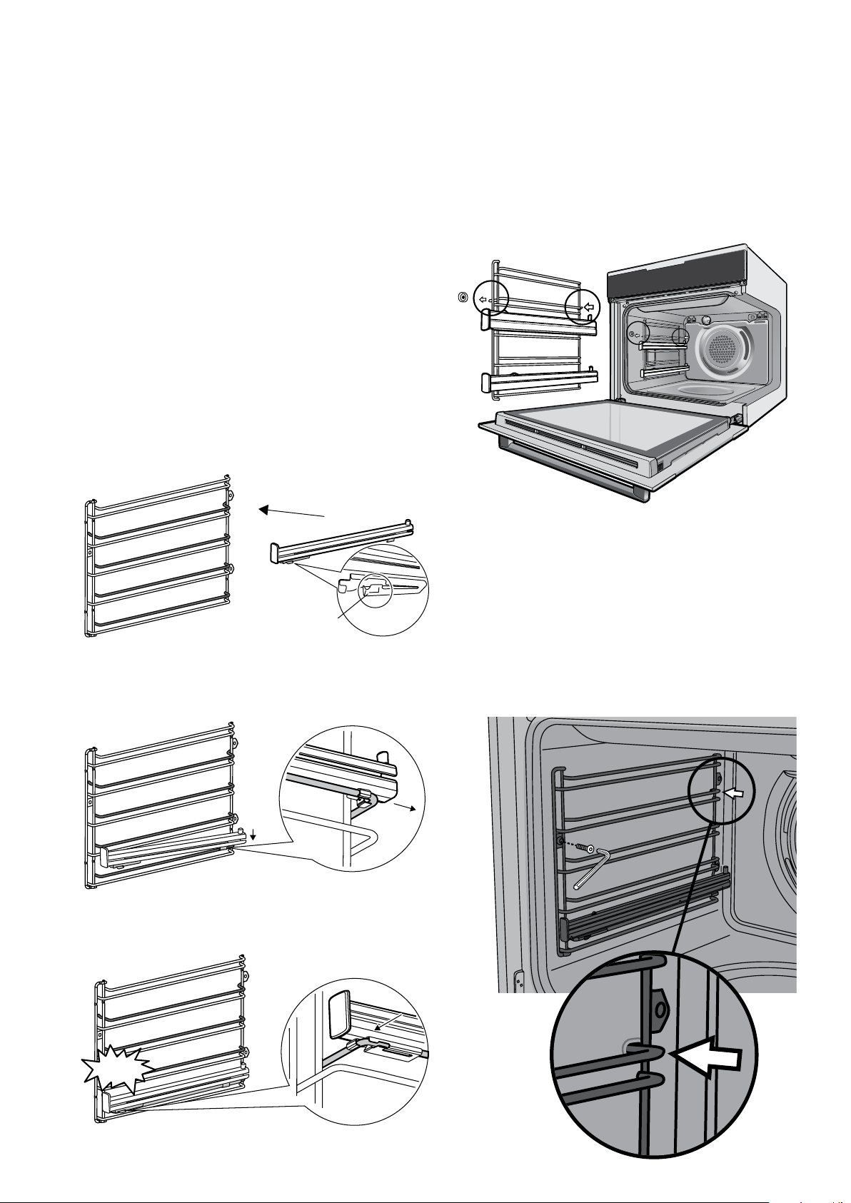
Pyro proof slides
1. Obtain left hand side rack and left hand slide – see
image to identify.
Side racks
1. Insert the rear peg into the rear access hole provided,
ensuring peg is fully inserted.
2. Then locate the front peg into the front access hole
and push in firmly.
NOTE: If you have purchased a two cavity appliance you
will have additional side racks for the lower oven/grill. These
are fitted in a similar manner.
L = left hand side
R = right hand side
2. The shaded wires indicate the wire the slide can be
mounted on. Fit slide rear clips to the rear of wire at an
angle as shown below.
1
3. Push slide front clip over wire until secured
2
3
Pyro proof side racks
1. Insert the rear peg into the rear access hole provided,
ensuring peg is fully inserted.
2. Then locate the front hole and insert screw.
3. Tighten with Allen key.
CLICK!
Page 22

22 electrolux.com.au
BEFORE USING YOUR APPLIANCE (CONTINUED)
Fitting the shelves and grill dish carrier between
the side rack wires
The shelves are designed so that they have maximum
extension but cannot be accidentally pulled right out.
The grill dish carrier is designed the same way and can
slot straight into the side racks.
To fit a shelf or grill dish carrier to side racks:
1 Locate the rear edge of the shelf/carrier in between
guide rails of the side rack - see diagram.
2 Ensure the same rail positions on both sides of the
oven are being engaged. With the front edge raised,
begin to slide the shelf into the oven.
3 Once the detents have passed the front edge of
the side rack, the shelf can be pushed completely
in. When fully inserted the shelf/carrier should not
interfere with the closed oven door.
Fitting the shelves and grill dish carrier onto
telescopic slides
To fit a shelf or grill dish carrier to telescopic slides:
1 With the slides fully pushed in, push the shelf/carrier
along the top of the slide until it hits the back post.
2 Drop the front of the shelf/carrier ensuring it sits
behind the front post of the slide (see illustration).
When fully inserted the shelf/carrier should not
interfere with the closed oven door.
Positioning the dishes on the grill dish carrier
AirFry Plus tray
Page 23
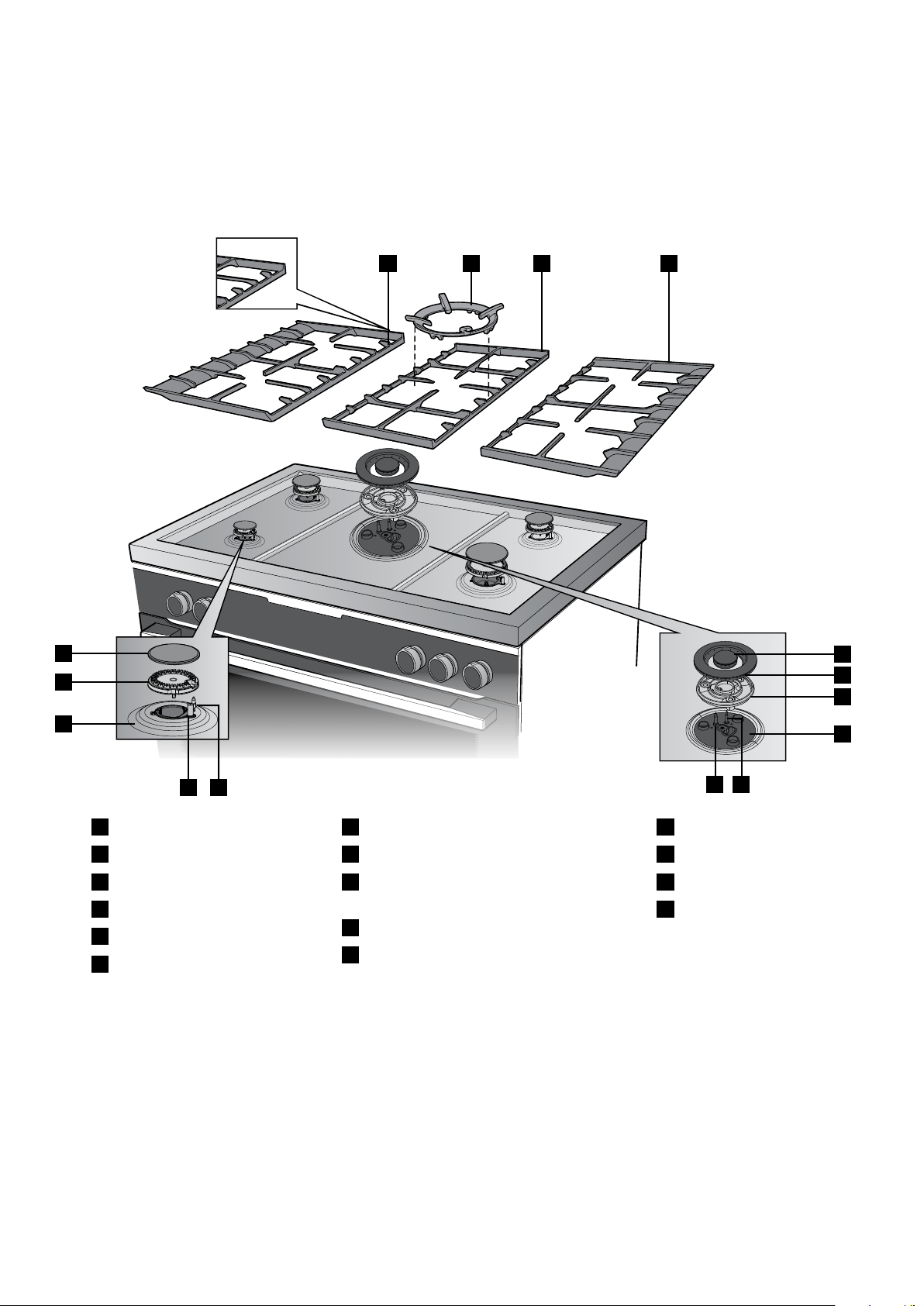
BEFORE USING THE APPLIANCE - GAS HOB MODEL
23
Installing the trivets
1. Position the 2 slide trivets onto the hob first, ensuring
the 2 corner location recesses are to the back of the
hob.
1 2 3 4
2. Position the middle trivet ensuring the trivet fingers are
aligned with the side trivet fingers.
3. The wok support sits on top of the trivet above the
wok burner.
5
6
7
9
8
1
Side trivet
2
Wok support
3
Middle trivet
4
Side trivet
5
Standard burner cap
6
Standard burner crown
7
Standard burner cup
8
Standard burner spark plug
9
Standard burner flame
safeguard sensor
10
Wok burner spark plug
11
Wok burner flame safeguard sensor
Installing the standard burners
1. The burner crown must be fitted correctly onto the
burner cap or damage will occur during operation.
2. To do this, align the outer hole and outer recess of
the burner crown around the spark plug and flame
safeguard sensor. Drop down ensuring the location
ribs on the bottom of the crown drop into the location
recesses.
12
13
14
15
10 11
12
Wok burner inner cap
13
Wok burner outer cap
14
Wok burner crown
15
Wok burner body
Installing the wok burners
1. The wok burner crowns must also be fitted correctly
onto the wok burner cups.
2. To do this, align the sausage shaped cutouts on the
burner crown with the sausage shaped cutouts on the
burner body. Drop down ensuring the centre location
pin of the crown has dropped into the corresponding
recess in the body.
3. Burner cap and burner crown must be clean and
located correctly for the burner to light.
3. The 2 burner caps are simply positioned over the top
of the burner crown.
NOTE: When the burners are correctly fi tted they will sit
level on the hob.
Page 24
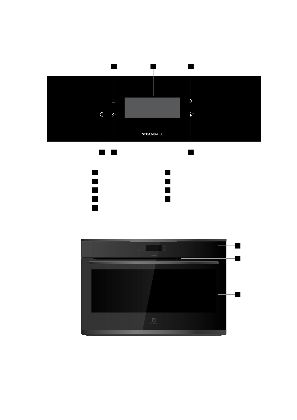
24 electrolux.com.au
EVEP916
EVEP916 DESCRIPTION
Multi function electric oven and programmable controller
4 5 6
1 2 3
1
ON/OFF
2
Favourites
3
Fast Heat Up button
4
Menu
5
Touch screen display
6
Light switch
7
Control panel
8
Warm air exhaust
9
Quadruple glazed door
7
8
9
Page 25
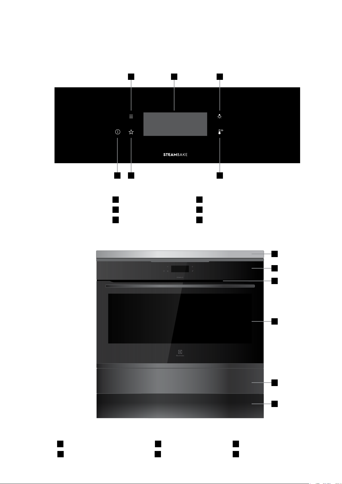
EVEP916
EFEP956DSE
EFEP956 DESCRIPTION
Induction hob, multi function electric oven and programmable controller
4 65
1 2 3
25
1
ON/OFF
2
Favourites
3
Fast Heat Up button
4
Menu
5
Touch screen display
6
Light switch
7
8
9
10
7
Induction hob
8
Control panel (see above)
9
Exhaust air outlet
10
Quadruple glazed door
11
12
11
Storage compartment
12
Removable kick panel
Page 26
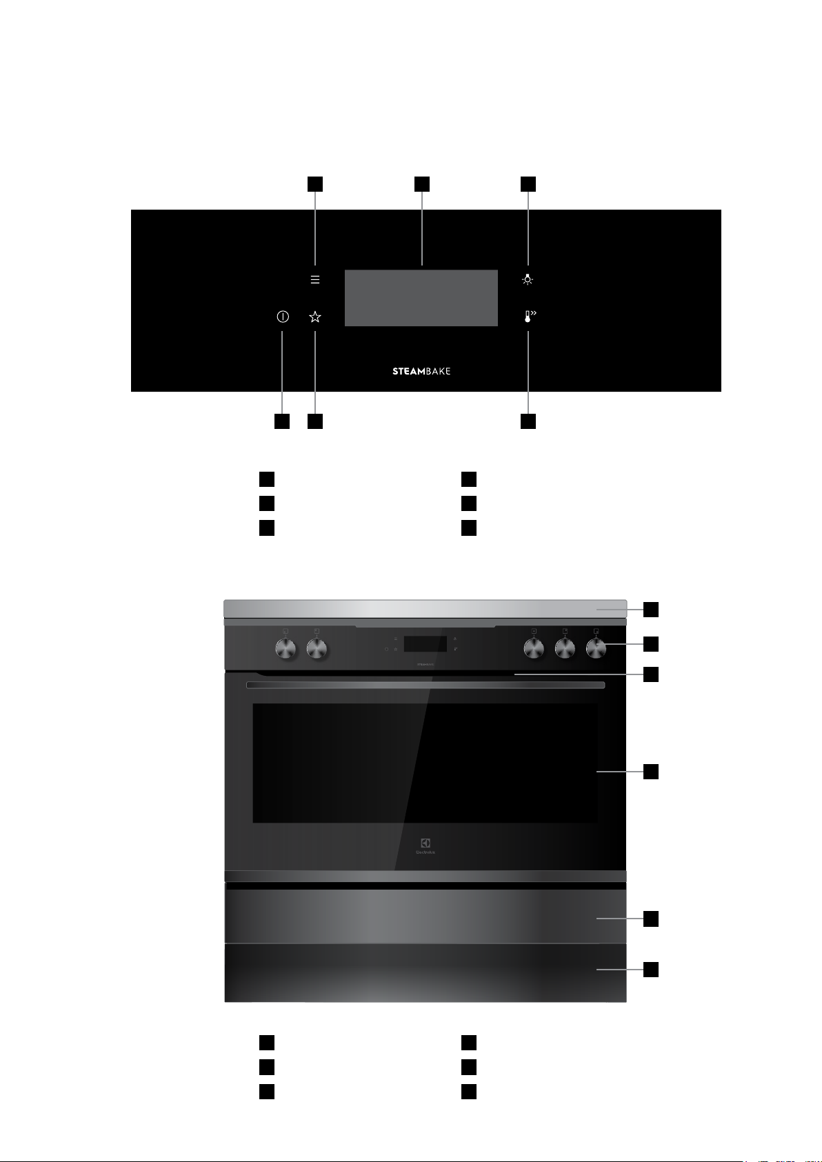
26 electrolux.com.au
EVEP916
EFEP916
EFEP956DSE
EFEP916 DESCRIPTION
Gas hob, multi function electric oven and programmable controller
4 5 6
1 2 3
1
ON/OFF
2
Favourites
3
Fast Heat Up button
4
Menu
5
Touch screen display
6
Light switch
7
8
9
10
7
Gas hob
8
Control panel (see above)
9
Exhaust air outlet
10
Quadruple glazed door
11
Storage compartment
12
Removable kick panel
11
12
Page 27
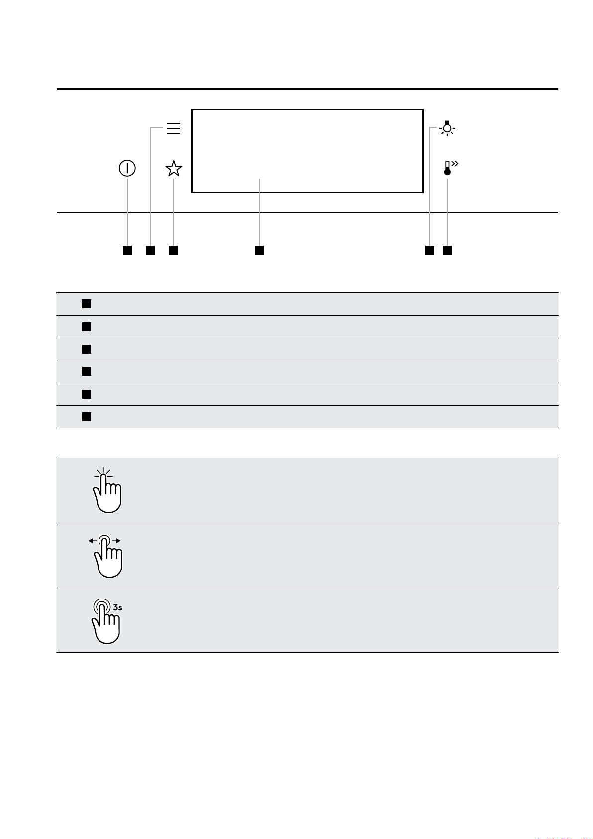
USING THE OVEN
1 2 3 5 64
27
1
2
3
4
5
6
On /off
Menu
Favourites
Touch display Shows the current settings of the oven
Light switch To turn the lamp on and off
Fast Heat Up To deactivate Fast Heat Up function
Press
Left/Right
swipe
Press and hold to turn the oven on and off
Lists the oven functions
Lists the favourite settings
Touch the surface with your ngertip
Slide ngertip over the surface
Press and
hold
Touch the surface for 3 seconds
Page 28
28 electrolux.com.au
A
USING THE OVEN (CONTINUED)
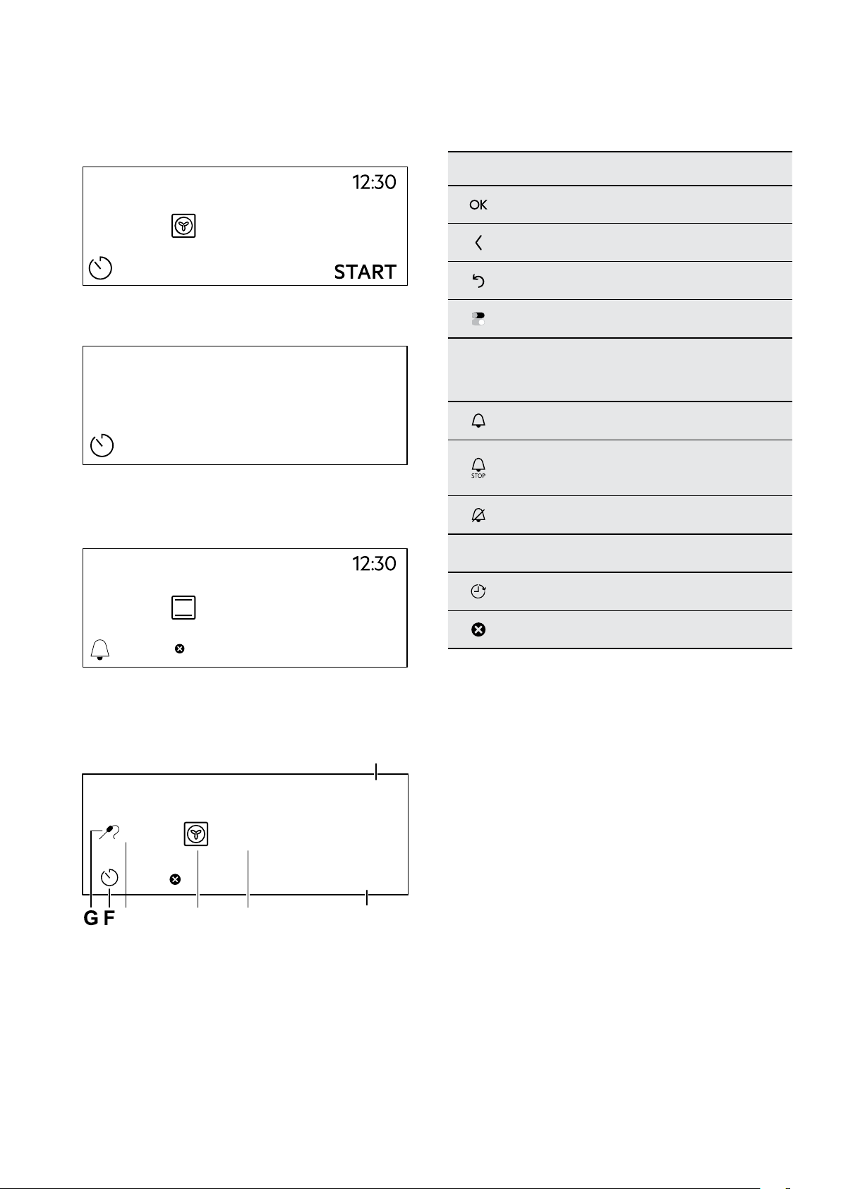
DI SPL AY
170˚C
How to turn the oven on and off
12:34
If you do not use the oven for 2 minutes, the display
goes to standby.
Display indicators
Basic indicators – to navigate on the display
To confirm the selection / setting
To go one level back in the menu
To undo the last action
To turn the options on and off
Sound alarm function indicators – when the set
time of cooking ends, the signal sounds
The function is on
The function is on.
Cooking stops automatically
Sound alarm is off
150°C
11min
When you cook, the display shows the set functions
and other available options.
85°C
15min
The display with the maximum number of functions set.
170˚C
DE
STOP
12:30
START
BC
Timer indicators
To set the function: delayed start
To cancel the setting
A. Time of day
B. Start / stop
C. Oven temperature
D. Heating functions
E. Food sensor/probe temperature
F. Timer
H. Food sensor/probe (selected models only)
Page 29
29
CONDITION THE OVEN
(TO BURN OFF ANY RESIDUE)
Preheat the empty oven before the first use.
1. Remove all accessories and removable shelf
supports from the oven.
2. Set the temperature to 180°C for the function: Fan
cooking
The oven can emit an odour and smoke during burn
off. Make sure that the room is ventilated.
. Let the oven operate for 30 minutes.
DAILY USE
WARNING
Refer to safety chapters
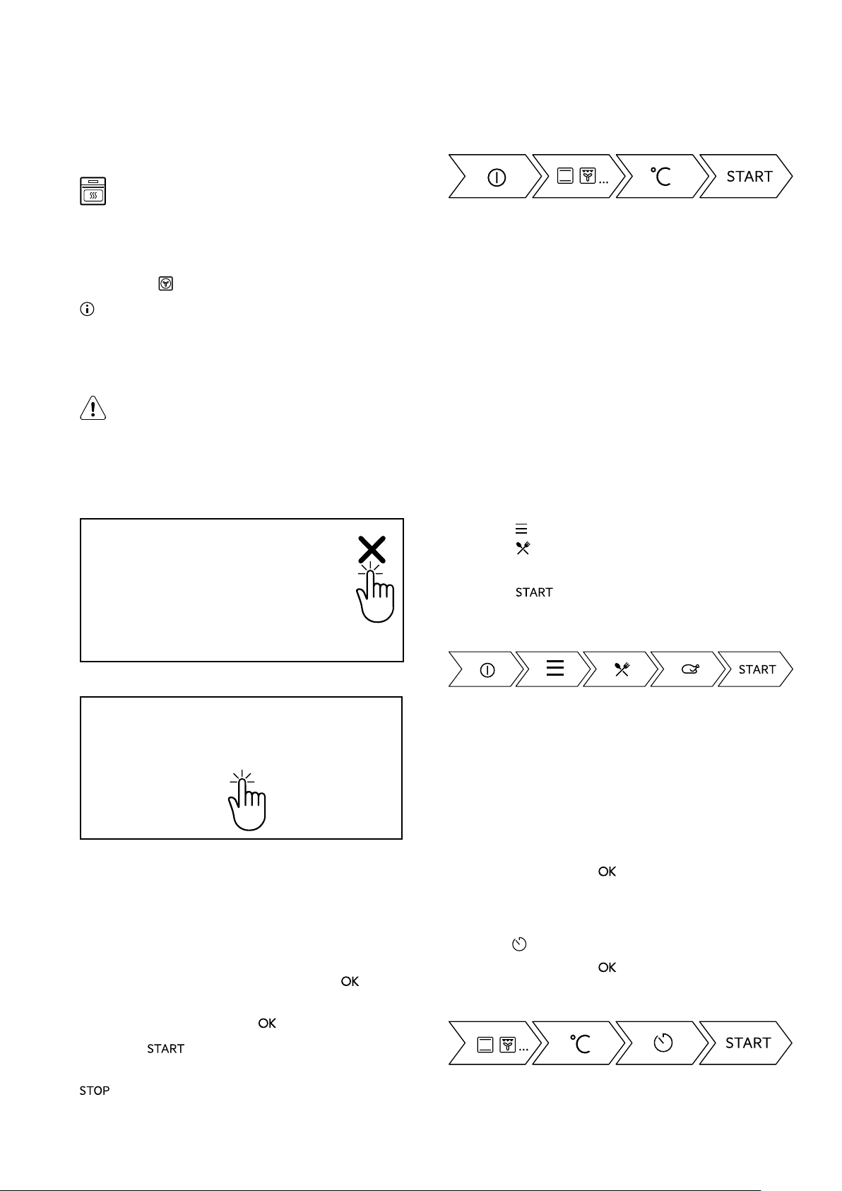
The touch screen display will display prompts or
messages. It will be necessary to touch the ‘X’
Message
Take a shortcut!
How to set Assisted Cooking
Every dish in this submenu has a recommended
function and temperature. You can adjust the time and
the temperature.
For some of the dishes you can also cook with:
• Weight Automatic
• Food Sensor/probe
The degree to which a dish is cooked:
• Rare or Less
• Medium
• Well done or More
1. Turn on the oven
2. Press: . Select: Settings / Connections
3. Press: . Enter: Assisted cooking.
4. Choose a dish or a food type.
5. Press:
or the middle of the message to respond.
Message
How to set Heating Functions
1. Turn ON the oven. The display shows the default
heating function.
2. Press the symbol of the heating function to enter
the submenu.
3. Select the heating function and press:
The display shows: temperature.
4. Set: temperature. Press:
Take a shortcut!
How to set Clock functions
How to set the clock
1. Turn ON
2. Press Menu
3. Go to Settings
4. Press Setup
5. Select: Time of day
6. Set the time. Press:
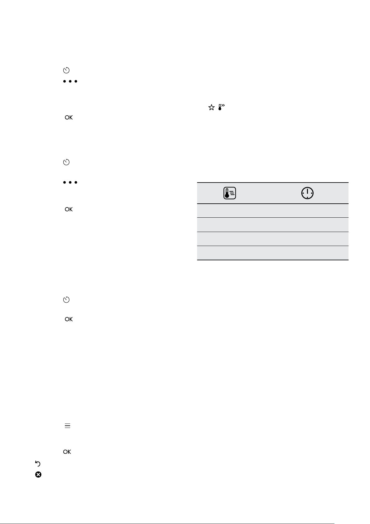
How to set cooking time
1. Choose a heating function and set the temperature.
2. Press
3. Set the time. Press:
Take a shortcut!
5. Press: . Food Sensor/probe - you can plug
the sensor at any time before or during cooking
– press to turn off the heating function.
6. Turn OFF the oven.
Page 30
30 electrolux.com.au
USING THE OVEN (CONTINUED)
How to choose end option
1. Press
2. Press
3. Select End action from timer
4. Press End action
5. Select preferred option
6. Press:
the main screen.
How to delay start of cooking
1. Set the heating function and the temperature.
2. Press
3. Set the cooking time.
4. Press
5. Press: Delayed start.
6. Choose the value.
7. Press:
the main screen.
How to extend cooking time
When 10% of cooking time is left and the food seems
not to be ready, you can extend cooking time. You can
also change the heating function.
Press +1min to extend the cooking time.
How to change timer settings
. Repeat the action until the display shows
. Repeat the action until the display shows
Function lock
This function prevents an accidental change of the
heating function.
1. Turn on the oven.
2. Select a heating function.
3.
, – press at the same time to turn on the
function lock.
To turn off the function lock repeat step 3.
Automatic switch off
For safety reasons the oven turns off after some time,
if a heating function works and you do not change any
settings.
(°c)
30 - 115 12.5
120 - 195 8.5
200 - 245 5.5
250 - maximum 3
The Automatic switch-off does not work with the
functions: Light, Food sensor/probe, End time, Slow
Cooking.
(h)
1. Press
2. Press the timer value.
3. Press:
You can change the set time during cooking at any time.
ADDITIONAL FUNCTIONS
How to save Favourites
You can save your favourite settings, such as the heating
function, the cooking time, the temperature or the
cleaning function. You can save 3 favourite settings.
1. Turn on the oven.
2. Select the preferred setting.
3. Press:
4. Select: Save current settings.
5. Press + to add the setting to the list of: Favourites.
Press
– press to reset the setting.
– press to cancel the setting.
. Select: Favourites.
Cooling fan
When the oven operates, the cooling fan turns on
automatically to keep the surfaces of the oven cool.
If you turn off the oven, the cooling fan can continue
to operate until the oven cools down.
Page 31

How to manage error codes
When the software error occurs, the display shows error message. In this section, you will find the list of the
problems that you can handle on your own.
31
Code and description
C2 – the Food sensor/probe is in the oven cavity
during Pyrolytic Cleaning.
C3 – the door is not fully closed during Pyrolytic
Cleaning.
Remedy
Take out the Food sensor/probe.
Close the door.
F111 – Food sensor/probe is not correctly
Fully plug Food sensor/probe into the socket.
inserted into the socket.
F240, F439 – the touch elds on the display do
not work properly.
Clean the surface of the display with micro bre cloth. Make
sure there is no dirt on the touch elds.
F908 – internal communication error Turn power OFF and ON.
When one of these error messages continues to appear, please contact our Customer Care Centre using the details
on the back page of this user manual.
Page 32
32 electrolux.com.au
STEAM ASSISTED COOKING
All Electrolux range of ovens have the ability to add steam
while baking.
Cooking with steam is a great addition to ‘hot air’ cooking.
Steam brings out all the natural flavours and goodness in
the food, cooks evenly from surface to centre and retains
more nutrients and vitamins. Steam assisted cooking
consistently produces juicy, succulent interiors with crisp,
golden exteriors.
WARNING
Risk of burns and damage to the appliance
• Do not open the appliance door when the steam
function operates, with the exception of preheating.
• Open the appliance door with care after the steam
function stops.
• Refer to cleaning the appliance for cleaning after the
steam function operates.
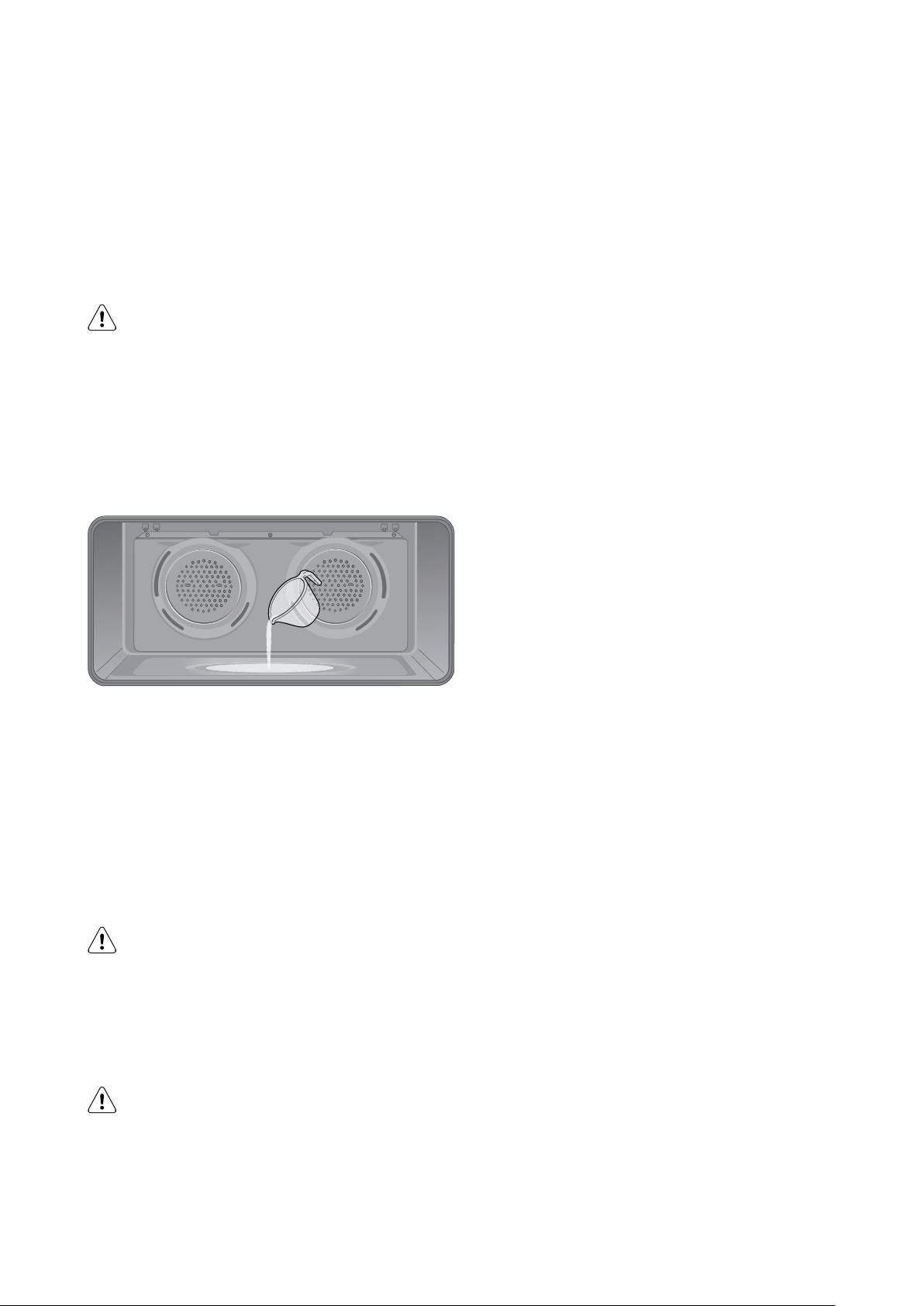
1. Open the oven door.
2. Add 150ml of tap water to the cavity well. Only add
water when the oven is cold.
3. Select any of the STEAM ASSIST functions.
4. Set the temperature and press START to commence.
5. Preheat the oven for 10 minutes or according to the
recipe suggestion.
6. Place food in the appliance and close the oven door.
CAUTION
Do not refill the cavity well with water during
cooking or when the oven is hot.
1. To deactivate the appliance, turn the knob for the oven
functions to off position.
2. Remove water from the cavity well.
WARNING
Make sure that the appliance is cool before you remove
the remaining water from the cavity well.
Page 33
USING THE FOOD SENSOR/PROBE
33
The Food Sensor/Probe measures the core temperature
of the food. When the food reaches the desired set core
temperature, the oven turns off. The Food Sensor/Probe
has a core temperature range of 50-99°C.
There are two temperatures to set:
• The oven temperature
• The core temperature of the food
WARNING
Only use the Food Sensor/probe supplied or the
correct replacement parts.
NOTE: Food must be completely defrosted when inserting
the Food Sensor/probe. If the food is too cold, the Food
Sensor/probe function will not work.
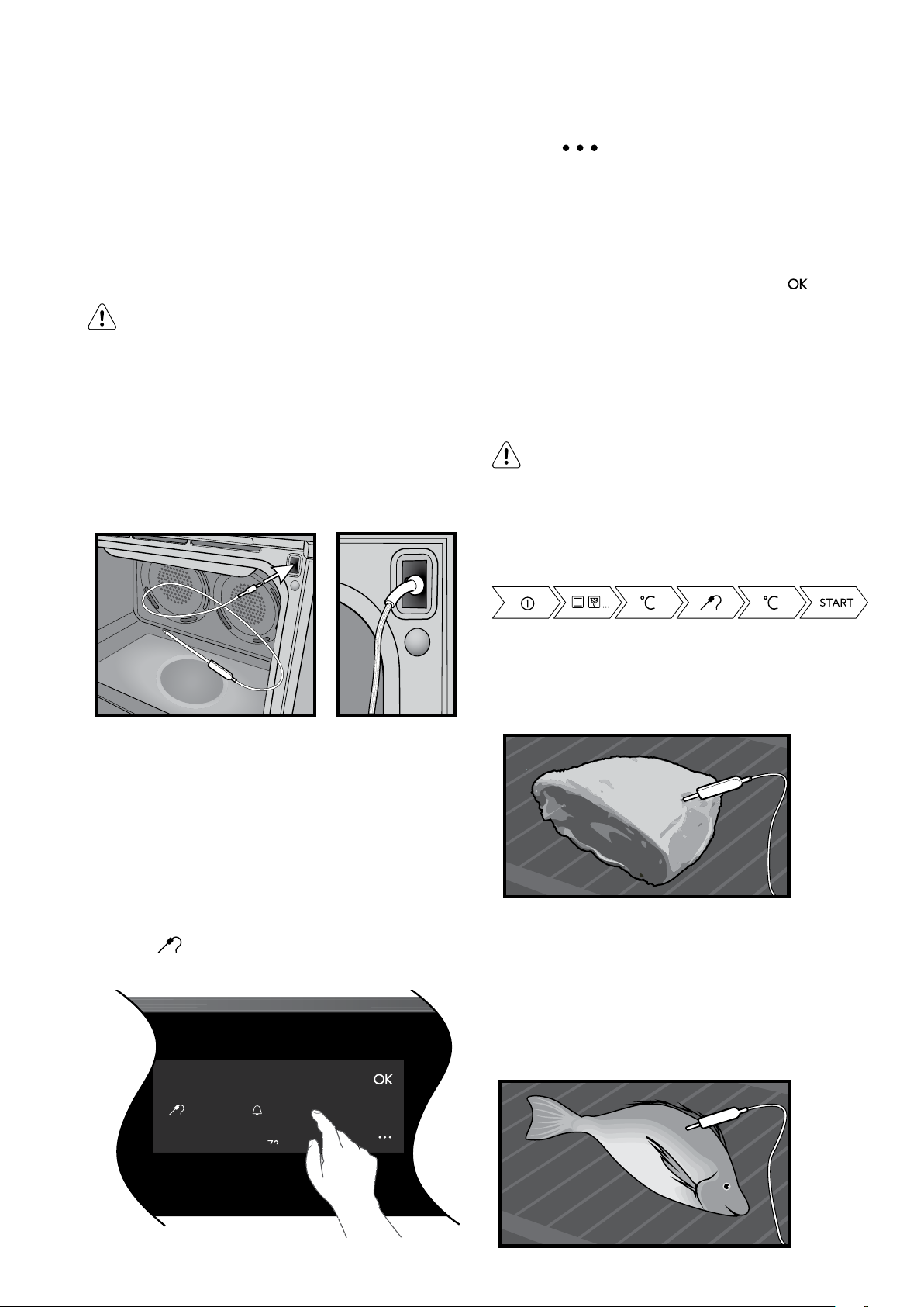
Put the plug of the Food Sensor/probe into the socket on
the top right hand corner of the front frame. Ensure the
plug is fully inserted into the socket.
6. Press to set the preferred option:
• Sound alarm – when the food reaches the core
temperature, the signal sounds.
• Sound alarm and stop cooking – when food
reaches the core temperature, the signal
sounds and the oven stops.
7. Select the option and repeatedly press:
the main screen.
8. Press: When food reaches the set temperature,
the signal sounds. You can choose to stop or to
continue cooking to make sure the food is well done.
9. Remove the Food Sensor/probe plug from the
socket and remove the dish from the oven.
WARNING
There is a risk of burns as the Food Sensor/Probe
becomes hot. Be careful when you unplug it and
remove it from the food.
Take a shortcut!
to go to
ALL FOOD SENSOR/PROBE MODELS
1. Turn on the oven.
2. Set a heating function and, if necessary, the oven
temperature.
3. Insert the Food Sensor/probe.
4. Plug the Food Sensor/probe into the socket at the
front of the oven. The display shows the current
temperature of the Food Sensor/probe.
5. Press
Sensor/probe.
to set the core temperature of the
Target Temperature
Meat
For large pieces of meat, insert the tip of the Food Sensor/
probe into the centre of the meat, with at least 75% of the
sensor/probe inserted into the meat.
Fish
For best results, place the whole fish onto the wire rack
and prop it up in the swimming position (i.e. using half
a potato or onion). Alternatively the fish can be laid flat.
Insert the Food Sensor/probe behind the head with at least
75% of the Sensor/probe inserted into the fish towards the
bones in the middle of the fish.
22˚C 70˚C
71
Page 34
34 electrolux.com.au
USING THE FOOD SENSOR/PROBE
Poultry
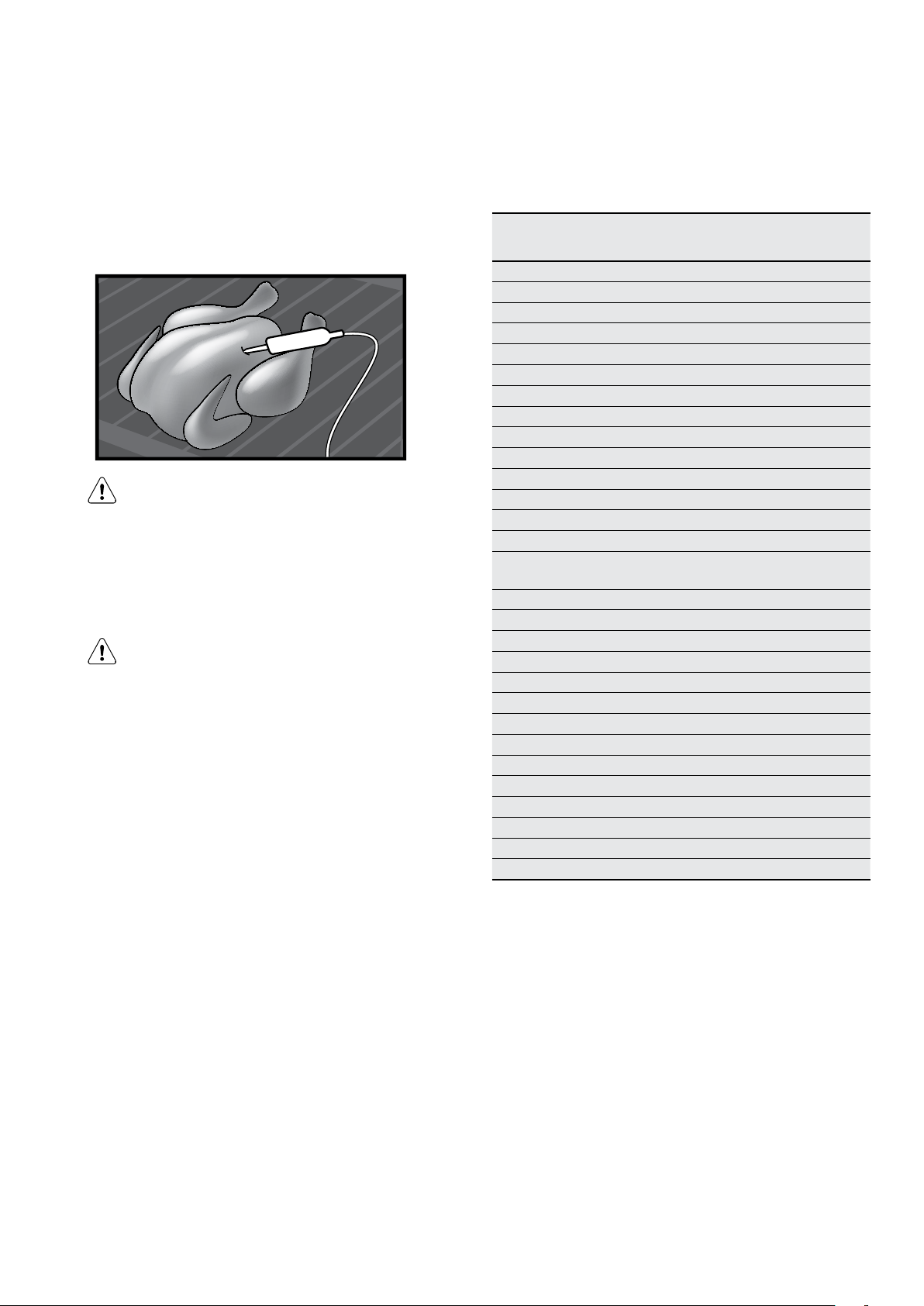
Place the whole poultry on the wire rack breast side up.
Insert the Food Sensor/probe with at least 75% of the
Sensor/probe into the breast of the poultry. Place the
Sensor/probe in a direction toward the neck end of the
poultry.
CAUTION
To prevent the Food Sensor/probe from being
damaged by excessive heat, there must be a gap
of a few centimetres between the grill element and
the Food Sensor/probe. The meat may expand
during the cooking process.
CAUTION
After pre-heating, the front of the oven will be hot.
Care should be taken when inserting the food
sensor/probe plug.
NOTE: The Food Sensor/probe will only work for the
following functions
• Fan cooking
• Steam cooking (EVEP618 / EVEP619 only)
• Traditional bake
• Fan assist bake
• Roast
If you have selected a function that is not compatible
with the Food Sensor/probe, you will see the message
“REMOVE FOOD PROBE”.
Core temperatures of different foods
The temperatures in the table are given as a guide and
may vary depending on the composition of the food.
Food Core
Poultry
Chicken 80-85
Chicken breast 75-80
Duck 80-85
Duck breast, rare to medium rare 55-60
Turke y 80-85
Turke y b re a st 80-85
Goose 80-90
Pork
Shoulder of pork 85-90
Fillet of pork, rare to medium rare 62-70
Loin of pork, well done 72-80
Beef
Tenderloin or sirloin, rare 45-52
Tenderloin or sirloin, medium rare
to medium
Tenderloin or sirloin, well done 65-75
Veal *
Joint of veal or shoulder, lean 75-80
Joint of veal, shoulder 75-80
knuckle of veal 85-90
Lamb **
Leg of lamb, medium rare 60-65
Leg or lamb, well done 70-80
Saddle of lamb, medium rare 55-60
Fish
Whole fish 65-70
Fish fillet 60-65
Miscellaneous
Meat loaf, all kinds 80-90
* Veal core temperatures are for well done.
** Lamb temperatures are for cuts of Lamb with the bone
still in. For boneless, cooking times will be slightly less.
NOTE: The oven temperature needs to be set at least 10°
higher than the desired food core temperature.
(CONTINUED)
Temperature in °C
55-62
7. The appliance will calculate the approximate end time.
The end time is different for different quantities of
food, set oven temperatures and function modes.
NOTE: The estimated end time will be displayed after
approximately 30 minutes.
Page 35
35
12:3012:30
81°C81°C
Heating up
81°C
95°C
STOPSTOP
12:3012:30
76°C
80°C
80°C
STOPSTOP
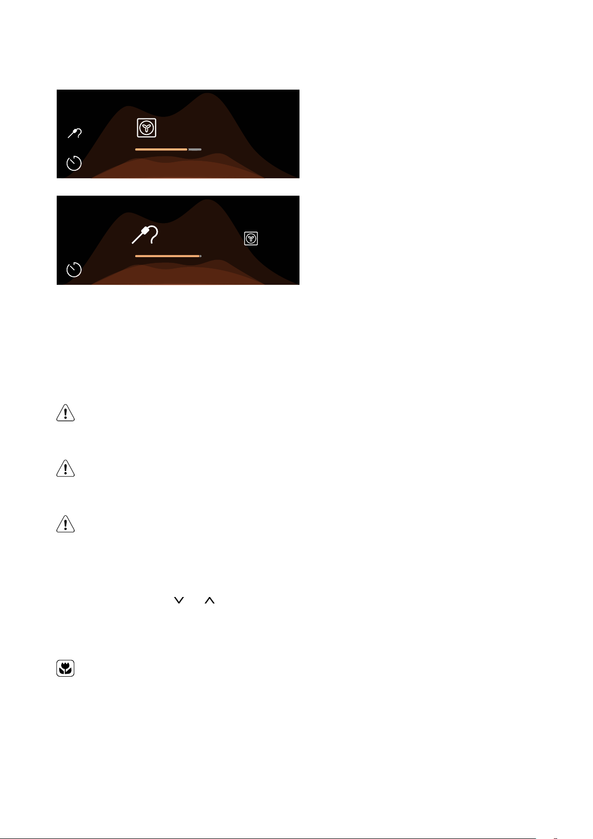
NOTE: The Food Sensor/probe temperature will not be
displayed until the oven is at the desired temperature.
Once the oven is at the desired temperature, the Food
Sensor/probe temperature will cycle between the
desired food core temperature and the actual food core
temperature.
NOTE: All meat/fish/poultry should be rested, covered for
at least 10 minutes.
CAUTION
Always check if food is cooked throughout
before eating.
WARNING
After use, always remove the Food Sensor/probe
from the oven cavity.
WARNING
The Food Sensor/probe is hot. There is a risk of
burns. Be careful when you remove the tip and
plug of the Food Sensor/probe.
To change the desired food core temperature during
cooking, press and hold the
To cancel the Food Sensor/probe operation, simply unplug
the sensor/probe from the socket.
ENVIRONMENT
To save energy and to help protect the
environment, we recommend these hints:
and at the same time.
Use the oven efficiently by cooking many trays of food at
the same time. For example:
• Cook 2 trays of scones, small cakes or sausage rolls.
• Cook a roast dinner at the same time as you cook
Page 36
36 electrolux.com.au
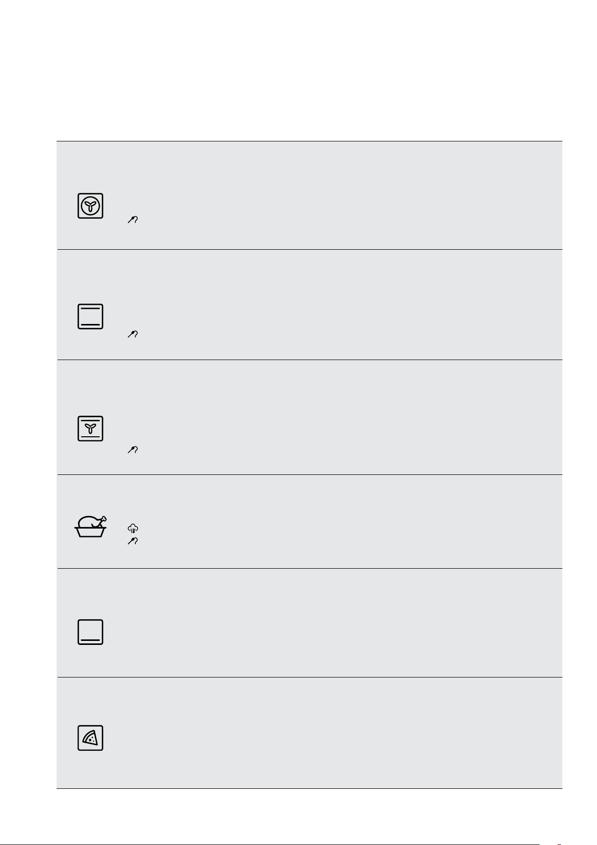
OVEN COOKING FUNCTIONS
COOKING FUNCTIONS - STANDARD (Functions listed may not apply to all models.)
Symbol Function description
Fan cooking
Traditional
bake
Fan assist
bake
Heat comes from the element surrounding the fan. This fan circulates the hot air around the oven cavity so that
you can put your food in different places in the oven and still cook them at the same time. You can use the ‘Fan
Cooking’ function for multi-shelf cooking, reheating cooked foods, pastries and complete oven meals. It will cook
at a lower temperature and be faster than baking. Please note that some variation in browning is normal.
NOTE: Food sensor/probe function can be introduced into this cooking cycle.
Heat comes from two elements, one above and one below the food. The bottom element is a clean heat
element and is below the floor of the oven. Both elements are controlled by the thermostat and will turn on and
off to maintain set temperature. You can use the ‘Traditional Bake’ function for single shelf cooking, single trays
of biscuits, scones, muffins, cakes, slices, casseroles, baked puddings, roasts and delicate egg dishes. This is a
general function that can be used for most cooking.
NOTE: Food sensor/probe function can be introduced into this cooking cycle.
Heat comes from two elements, one above and one below the food. The fan circulates the hot air around the
oven cavity so that you can put the food in different places in the oven and still cook them at the same time. You
should only use a maximum of two shelves with ‘Fan Assist Bake’.
Do not use the bottom shelf. If the two shelves are used, food on the shelf in the higher position will cook first
and should then be removed to allow the food on the lower shelf to finish cooking.
NOTE: Food sensor/probe function can be introduced into this cooking cycle.
Roast
Pastry
Pizza
The Roast function is designed for roasting meats, poultry and fish by utilising heat from all elements in
combination with the fan to surround the food. This provides even cooking throughout and enhanced browning.
NOTE: EVEP618 / EVEP619 gives you the option to introduce steam into this cooking cycle.
NOTE: Food sensor/probe function can be introduced into this cooking cycle.
The ‘Pastry’ function is specially designed for food that require extra browning such as the bases of pastries and
pies. Heat comes from the element below the food. If you choose the default setting, the oven will heat up to
230°C in order to brown the food.
You should then lower the temperature as required. Cook in the lower half of the oven when you are using only
one shelf.
‘Pizza’ is a combination of ‘Pastry’ and ‘Fan Assist Bake’ and offers you the combined benefits of both functions.
Heat switches between the element surrounding the fan and the clean heat element below the oven floor.
The ‘Pizza’ function is ideal for foods that require cooking and browning on the base. It is for foods such as
pizzas, quiches, meat pies and fruit pies. Simply place the food in the middle of the oven and set the desired
temperature.
Page 37
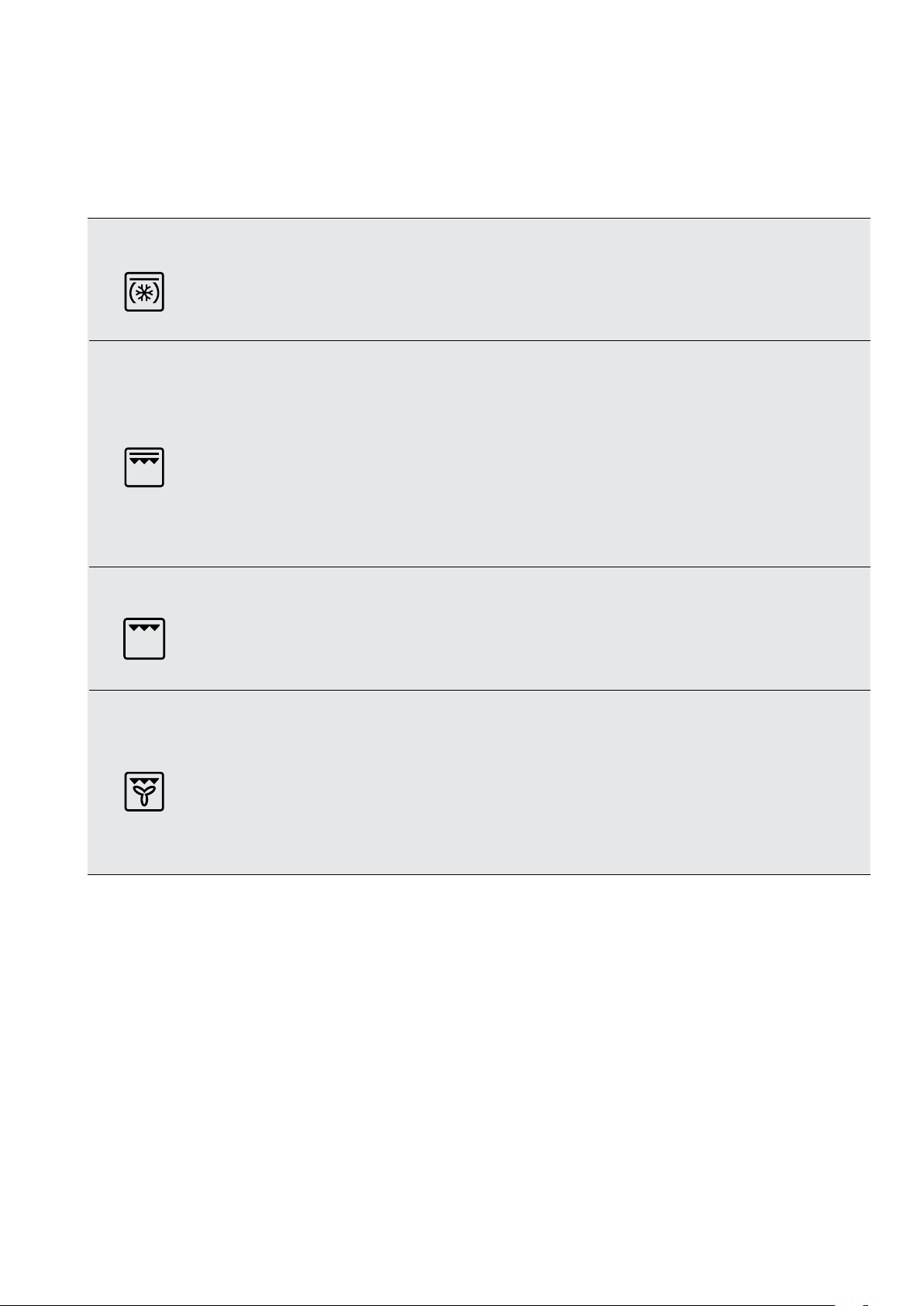
COOKING FUNCTIONS (CONTINUED)
Symbol Function description
37
Cook from frozen
Grill boost
Grill
The ‘Cook from Frozen’ function is ideal for cooking frozen precooked foods such as savoury pastries, pizzas,
mini meals (TV dinners), meat pies and fruit pies. Heat comes from the element surrounding the fan as well as
a smaller element above the food. Simply place the food in the oven straight from the freezer and heat. Cook in
the upper half of the oven for best results.
‘Grill Boost’ direct radiant heat from two powerful upper elements onto the food. You can use ‘Grill Boost’
function for tender cuts of meat, steak, chops, sausages, fish, cheese toasties and other quick cooking foods.
Grill with the oven door closed.
‘Grill Boost’ allows you to take full advantage of the large grill dish area and will cook faster than the ‘Grill’
function. For best results it is recommended to preheat your grill for three minutes. This will help seal in the
natural juices of steak, chops etc for a better flavour.
Place the grill shelf in position 4 with the grill dish below to catch any spills. ‘Grill Boost’ has 2 temperature
settings, ‘LO’ and ‘HI’.
The ‘Grill’ directs radiant heat from only one of the powerful upper elements onto the food. The ‘Grill’ function
is used instead of ‘Grill Boost’ when only half the amount of heat is needed. ‘Grill’ has 2 temperature settings,
‘LO’ and ‘HI’.
Grill with the oven door closed.
Fan grill
‘Fan Grill’ offers you the benefits of both traditional bake and traditional grill functions. The grill element turns on
and off to maintain set temperature while the fan circulates the heated oven air.
Grill with the oven door closed.
You can use ‘Fan Grill’ for large cuts of meat, which gives you a result similar to ‘rotisserie’ cooked meat. Place
your food on the grill shelf in position 2 with the grill dish below to catch any spills. When using ‘Fan Grill’ it is not
necessary to turn the food over during the cooking cycle. Set temperature to 180°C.
Page 38
38 electrolux.com.au
OVEN COOKING FUNCTIONS (CONTINUED)
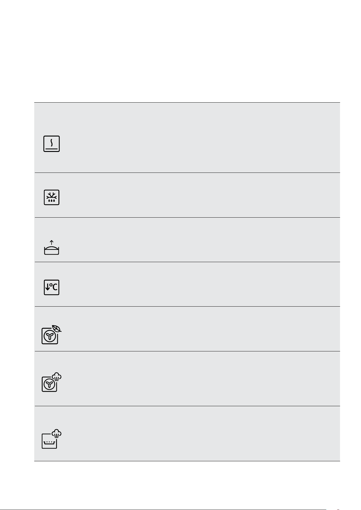
COOKING FUNCTIONS – SPECIAL
(Functions listed may not apply to all models.)
Symbol Function description
The ‘Keep Warm’ function is a low temperature oven function designed to keep your food at a perfect eating
Keep warm
temperature without cooking it further. Heat comes from the smaller elements above the food and is circulated by the
fan. Use ‘Keep Warm’ to keep your food warm while you prepare the rest of the meal or afterwards while you wait for
the late arrival.
NOTE: After cooking, the oven retains enough heat to continue to cook food even if the elements are turned off. The
‘Keep warm’ function recognises this by giving you a warning message. If this happens the function will
not start.
Defrost
Dough
proving
Slow
cooking
Eco mode
The ‘Defrost’ function uses low temperature air that is circulated by the fan. You can defrost (thaw) your food before
you cook it. You can also use ‘defrost’ to raise your yeast dough and to dry fruit, vegetables and herbs. The ‘Defrost’
function does not have a suggested temperature but uses the ambient heat in the oven cavity.
The Dough Proving function offers ideal humidity and heat which speeds up and improves the dough proving,
prevents surface drying and keeps the dough elastic.
The Slow Cooking function is great for gentle and slow cooking of lean and tender pieces of meat and fish.
Eco mode function is designed to save energy during cooking. The oven retains moisture in the cavity and runs in
energy-saving mode
SteamBake
AirFr y Plus
Adding steam to your baking program can lift your baking skills to a whole new level.
Shelf guide: position 3. (See diagram on page 41)
EVEP618 / EVEP619 only
Using the dedicated tray with this function delivers great tasting foods that are crisper with juicy centres. Shelf
guide: AirFryPlus Tray position 3 and catch tray position 1. (See diagram on page 41)
Page 39

MENU
Main menu
39
Press:
Menu item
Assisted cooking
Cleaning
Favourites Lists the favourite settings.
Options To set the oven conguration.
Settings Setup To set the oven conguration
Submenu for Pyrolytic Cleaning – Applicable to Pyrolytic models only
Submenu
Quick
to open Menu
Application
Lists automatic programmes.
Lists cleaning programmes.
Service Shows the software version and conguration
Application
Duration: 1 hour 30 minutes
Normal
Intense Duration: 2 hours 30 minutes
Submenu for Options
Submenu
Light
Child lock
Fast heat up Shortens heat up time. It is available only for some of the oven functions.
Cleaning Reminder Turns the reminder on and off.
Time indication Turns the clock on and off.
Application
Turns the light on and off.
Prevents accidental activation of the oven. When the option is on, the text "Child
Lock" appears on the display when you turn on the oven. To enable the oven use,
choose the code letters in the alphabetical order. When the Child Lock is on and the
oven is turned off the oven door are locked.
Duration: 2 hours
Digital clock style Changes the format of the displayed time indication.
Page 40

40 electrolux.com.au
MENU (CONTINUED)
Submenu for Setup
Submenu
Language
Display brightness
Key tones
Buzzer volume Sets the volume of key tones and signals.
Time of day Sets the current time and date.
Submenu for Service
Submenu
Demo mode
Software version
Application
Sets the oven language.
Sets the display brightness.
Turns the tone of the touch elds on and off. It is not possible to mute the tone for
.
Application
Activation / deactivation code: 2468
Information about software version.
Reset all settings Restores factory settings.
Page 41
OVEN BAKING GUIDE
Oven shelf location
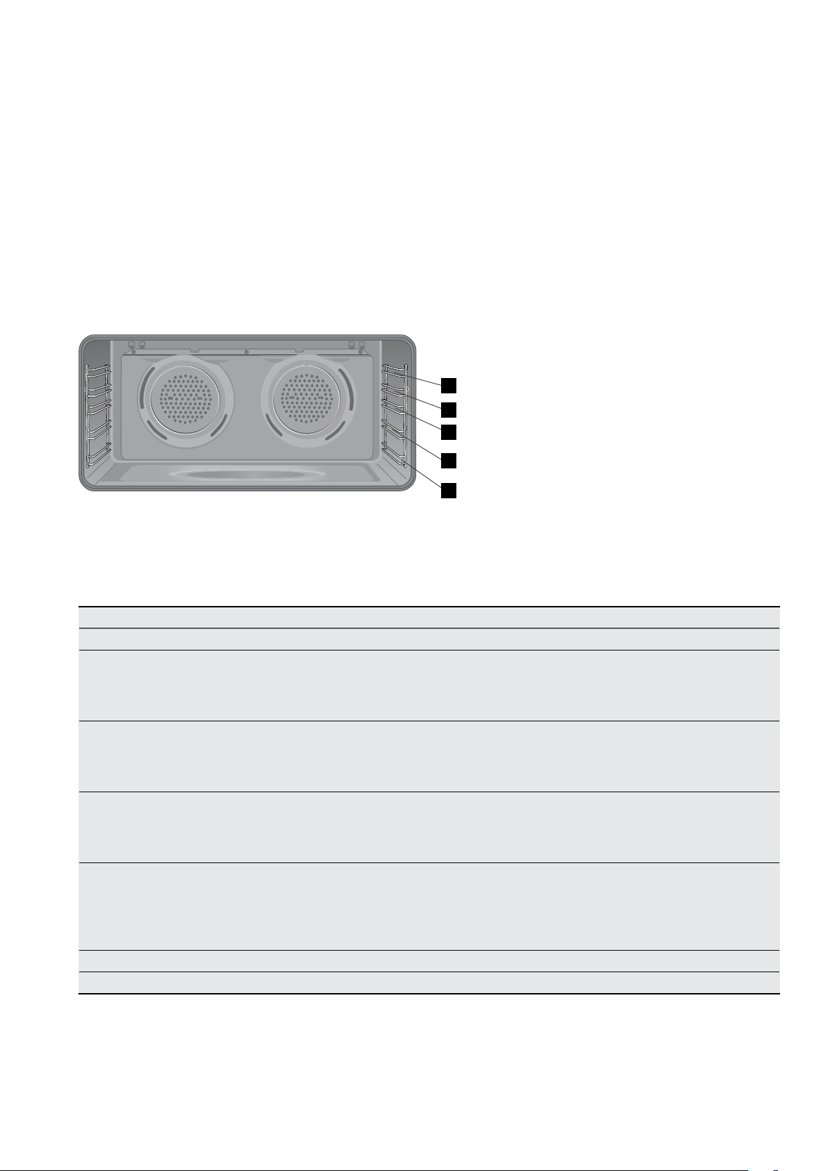
Your oven has 5 positions for mounting the shelves or grill dish carrier. These are
numbered from 1 (the lowest shelf position) to 5 (the highest shelf position). See diagram.
To give maximum space above and below the shelves, load them in this way:
• When cooking with 1 shelf, use position 2 or 3.
• When cooking with 2 shelves, use position 1 and 3.
• When grilling use position 4 or 5.
NOTE: Use the oven efficiently, by cooking many trays of food at the same time
e.g. 2 trays of scones, small cakes or sausage rolls.
5
4
3
41
2
1
Choosing the best oven settings
The following table is intended as a guide and experience may show some variation in cooking times necessary
to meet individual requirements. We recommend that you preheat your oven for 30 minutes.
Modes without Oven Fan
Food Temperature ˚C Oven shelf position* Time in minutes
Scones Plain or fruit 220 2 or 3 10 – 15
Biscuits Rolled
Spooned
Shortbread biscuits
Meringues Hard - individual
Soft - individual
Pavlova - 6 egg
Cakes Cupcakes
Sponge - 4 egg
Shallow butter cake
Pastry – short crust Cornish pasties
170
190
160
110
180
110
190
180
180
200
3
3
3
3
3
3
2 or 3
2 or 3
3
3
13 – 18
13 – 18
30 – 35
90
15 – 20
75
15 – 20
20 – 30
25 – 30
40 – 45
Custard tart
200/180
3
Pastry 8/200
Whole tart 10/200
& 20/180
Pastry – choux Cream puffs 210 3 25 – 30
Yeast goods Bread 210 3 25 – 30
Page 42

42 electrolux.com.au
OVEN BAKING GUIDE (CONTINUED)
Modes with Oven Fan
Food Temperature ˚C Oven shelf position* Time in minutes
single shelf
Scones Plain or fruit 210 2 or 3 1 & 3 10 – 15
Biscuits Rolled 150 2 or 3 1 & 3 13 – 18
Spooned 180 2 or 3 1 & 3 13 – 18
Shortbread 150 2 or 3 1 & 3 13 – 18
Meringues Hard – individual 100 2 or 3 1 & 3 90
Soft – individual 165 2 or 3 1 & 3 15 – 20
Pavlova – 6 egg 10 0 2 or 3 1 & 3 75
Cakes Cupcakes 180 2 or 3 1 & 3 15 – 20
Sponge – 4 egg 170 2 or 3 1 & 3 20 – 30
Shallow butter cake 170 2 or 3 1 & 3 25 – 30
Rich fruit cake 170 2 or 3 1 & 3 60
Pastry – short
crust
Pastry – choux Cream puffs 200 2 or 3 1 & 3 25 – 30
Yeast goods Bread 200 3 1 & 3 25 – 30
Cornish pasties 180 2 or 3 1 & 3 40 – 45
Custard tart 19 0 /170 2 or 3 1 & 3 20 – 30
Whole tart Pastr y 8/19 0
multi shelf
Whole tart 10/190
& 20/170
* Counting from the bottom shelf up.
SteamBake function
Food Water in cavity
well (ml)
Yeast goods Bread loaves 200 180 - 200 2 or 3 35 - 45
Bread rolls 200 190 - 210 2 or 3 20 - 25
Gluten free bread 200 180 - 200 2 or 3 40 - 50
Pizza (fresh) 200 210 - 220 2 or 3 15 - 20
Focaccia 200 160 - 170 2 or 3 20 - 30
Biscuits Rolled 200 160 - 170 2 or 3 10 - 15
Spooned 200 160 - 170 2 or 3 10 - 15
Scones Plain or fruit 200 200 - 210 2 or 3 10 - 15
Cake Cupcakes 200 180 2 or 3 20 - 25
Sponge – 4 eggs 200 170 2 or 3 20 - 30
Shallow butter cake 200 170 2 or 3 25 - 30
Pastry – choux Cream puffs 200 200 2 or 3 20 - 30
Puff pastry 200 200 2 or 3 15 - 20
Frozen croissants 200 170 - 180 2 or 3 15 - 25
Temperature °COven shelf
position*
Time in
minutes
*Counting from the bottom position up
Page 43
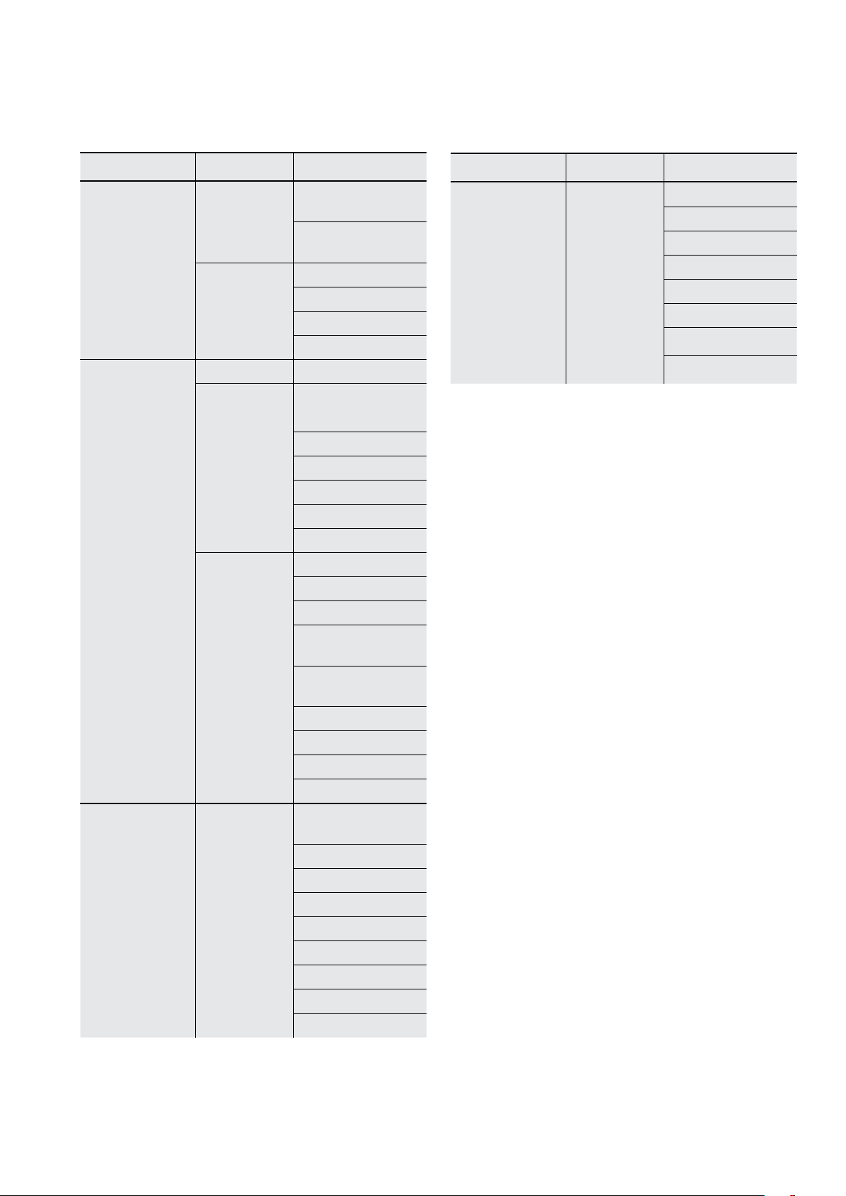
Assisted cooking recipes
43
Food category Type of food Type
Side / Oven
Dishes
Side Dishes
Jacket Potato
Wedges
Hash Browns
Oven Dishes Lasagne
Potato Gratin
Pasta Bake
Vegetable Gratin
Savoury Baking Pizza Pizza
Quiche Quiche
Bread Ciabatta
Rolls
Baguette
Wholegrain Bread
White Bread
Dark Bread
Cake in Tin Almond Cake
Food category Type of food Type
Small Pastry Cakes, small
Cream Puffs
Eclairs
Macaroons
Mufns
Pastry Strips
Puff Pastry
Shortbread
Desserts /
Sweet Baking
Apple Pie
Baked Cheesecake
Apple Cake,
covered
Short crust pastry
case
Sponge an case
Madeira Cake
Sponge Cake
Tarts
Cake on Tray Apple Strudel, froz.
Baked Cheesecake
Christmas Stollen
Sponge Cake
Sugar Cake
Swiss Roll
Swiss Tarte, sweet
Yeast Cake
Brownies
Page 44
44 electrolux.com.au
OVEN COOKING GUIDE
Roasting meat
1 Place the meat in the oven and set the temperature
between 180°C and 200°C. (It is recommended
to wrap your meats in an oven roasting bag or foil
to prevent fats and oils from splattering, making it
easier to clean your oven.)
2 Use the grill/oven dish and grill insert.
Place the meat on the insert.
3 Do not pierce the meat, as this will allow juices
to escape.
4 When the meat is cooked, take the roast out of
the oven, wrap in aluminium foil and leave to stand
for about 10 minutes. This will help retain the
juices when the meat is carved. The table shows
temperatures and cooking times for different
kinds of meat. These may vary depending on the
thickness or bone content of the meat.
Meat Recommended
temperature
Beef 180°C - 200°C Rare 35 - 40
Medium 45 - 50
Well done 55 - 60
Lamb 180°C - 200°C Medium 40
Well done 60
Veal 180°C - 200°C Well done 60
Pork 180°C - 200°C Well done 60
Roasting poultry and fish
1 Place the poultry or fish in an oven set at a
moderate temperature of 180°C.
2 Place a layer of foil over the fish for about three
quarters of the cooking time.
The table shows temperatures and cooking times
for different kinds of fish and poultry. These may vary
depending on the thickness or bone content of the meat.
Poultry &
Fish
Chicken 180°C - 200°C 45 - 50
Duck 180°C - 200°C 60 - 70
Turke y 180°C - 200°C 40 - 45 (>10kg)
Fish 180°C - 200°C 20
Recommended
temperature
35 - 40 (<10kg)
Minutes
per kilogram
Minutes
per kilogram
GRILLING GUIDE
WARNING!
Always clean the grill/oven dish after every use.
Excessive fat build-up may cause a fire. Grilling
is conducted with the oven door closed.
As a method of cooking, grilling can be used to:
• Enhance the flavours of vegetables, fish, poultry and meat.
• Seal the surface of the food and retain the natural juices.
This table shows how to grill different types of meat:
Beef
Lamb Loin chops, short loin chops, chump
Sausages Prick sausages to stop skin from bursting.
Poultry Divide into serving pieces. Brush with oil.
Fish
Bacon Remove rind. Grill flat.
Guide to better grilling
Steak 15 - 20 minutes
Chops 20 - 30 minutes
Fish 8 - 10 minutes
Bacon 4 - 5 minutes
No definite times can be given for grilling because
this depends on your own tastes and the size of the
food. These times should only be used as a guide and
remember to turn the food over halfway through the
cooking process.
For better grilling results, follow these easy instructions:
1 Preheat grill for at least 5 minutes.
2 Choose only prime cuts of meat or fish. If the cut is
less than 5mm thick it will dry out. If the cut is more
than 40mm thick, the outside may burn whilst the
inside remains raw.
3 Do not place aluminium foil under the food as this
prevents fats and oils from draining away, which could
result in a fire.
4 Baste the food during cooking with butter, olive oil
or marinade. Grilled food is better if marinated
before cooking.
5 Use tongs to turn food as a fork pierces the surface
and will let juices escape.
Fan Grill
The “Fan Grill” assists the grilling process by circulating
the heat evenly around the food. The recommended
temperature setting is 180°C for all fan grilling functions.
1 Place the grill dish on the bottom rack.
2 Place meat/poultry on an oven shelf above
the grill dish.
3 Wipe off any oil or fat which spatters while
the oven is still warm.
Tenderloin, rump, sirloin. Brush with oil or
melted butter, especially if meat is very lean.
chops, and forequarter chops. Remove
skin or cut at intervals to stop curling.
Brush with oil or melted butter.
Brush with oil or melted butter and lemon juice.
Page 45
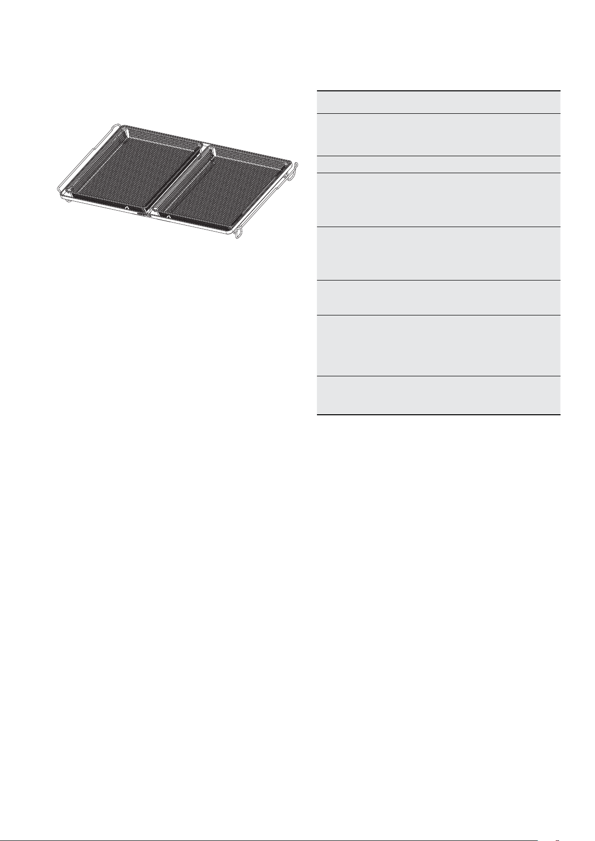
45
AirFry Plus cooking
The AirFry Plus feature works best for single shelf baking.
AirFry plus is suitable for French Fries, Chicken Wings,
Chicken Nuggets and similar products, see settings in the
following table.
Important:
• AirFry Plus is designed for single shelf cooking.
• Food should be arranged in a single layer on the AirFry
Pl u s tray.
• A separate tray should be placed on the bottom shelf
position to catch any fat or crumbs dropping from
the AirFry Plus tray during cooking. This tray must be
removed for normal baking.
• Some experimenting may be required to find the best
cooking time.
food Te mp
Scotch fillet
steak, seared
220 2 or 3
first
Shelf
position*
Time in
minutes
8-12
(rare/med)
Frozen chips 220 2 or 3 15-20
Chicken
drumettes/
wingettes with a
220 3 15-20
dry rub
Fresh
barramundi fillet
220 3 15-20
with crumb
Potatoes cut
into wedges
220 3 20-25
Frozen goods
(Chicken
nuggets/
220 3 15-20
crumbed fish)
Smashed chats
parboiled
220 3 15-20
*Count shelf position from the bottom up.
• Food may need to be removed early and should be
checked at minimum recommended bake time.
• Some frozen dense food with cook times less than 15
minutes may require additional baking time.
To set the AirFry Plus function:
1. Arrange food on to the AirFry Plus tray.
2. Select AirFry plus setting and suggested temperature
from the table below.
3. For best results pre-heat the oven
4. When the oven reaches the set temperature place the
AirFry Plus tray on the suggested oven shelf position.
Note: Set the minute minder for the minimum
suggested time and check for desired results when
timer ends.
5. When cooking is complete turn the oven off.
6. Clean the AirFry Plus tray after each use. Wash the
tray in the sink with warm soapy water and a stainlesssteel scourer.
Page 46

46 electrolux.com.au
DEALING WITH COOKING PROBLEMS
Problem Causes Remedies
Uneven cooking: Incorrect shelf position.
Oven tray too large.
Select shelf that puts food in the centre of
the oven.
Experiment with other trays or dishes.
Baked products too brown
on top:
Baked products too brown
on bottom:
Cakes have a cracked,
thick crust:
Trays not centralised.
Air flow in oven uneven.
Grill dish affecting thermostat.
Oven not preheated.
Baking tins too large for the recipe.
Baking tins not evenly spaced.
Products not evenly sized or spaced
on trays.
Baking temperature too high.
Baking tins too large for the recipe.
Baking tins are dark metal or glass.
Food too low in the oven.
Oven door opened too frequently
during baking.
Baking temperature too high.
Grill dish affecting thermostat.
Baking temperature too high.
Food too high in oven.
Centre trays.
Rotate food during cooking.
Remove grill dish from oven on bake modes.
Preheat the oven.
Use correct size tins.
Stagger baking tins at least 3cm
between tins and the oven walls.
Make into same size and shape,
and spread evenly over trays.
Lower the temperature.
Use correct size tins.
Change to shiny, light tins or lower the
temperature by 10°C.
Cook one shelf higher.
Don’t open the oven door until at least
half the cooking time has passed.
Lower the temperature.
Remove grill dish from oven on bake modes.
Lower the temperature.
Cook one shelf lower.
Cake batter over mixed.
Pan too deep.
Baking pans dark.
Baked products are pale,
flat and undercooked:
Cakes fallen in the centre: Baking temperature too low.
Roast meat & potatoes not
browning in fan oven:
Juices running out of meat: Do not pierce meat with fork, turn with tongs.
Grilled meats overcooked on
outside & raw in the centre:
Grilled chops & steaks
curling:
Baking temperature too low.
Food too low in oven.
Baking time too short.
Incorrect tin size.
Baking time too short.
Proportions of ingredients
incorrect in the recipe.
Opening door too early in baking.
Poor hot air circulation.
Grill dish affecting thermostat.
Mix just long enough to combine ingredients.
Check size of pan and use recommended
size.
Change to shiny pans.
Raise the temperature.
Cook one shelf higher.
Increase cooking time.
Use correct size tin.
Raise the temperature.
Increase cooking time.
Check recipe.
Do not open the door until the last quarter
of cooking time.
Elevate food onto a rack to allow air
circulation.
Remove grill dish from oven on bake modes.
Grill at lower insert position.
Cut into fat every 2cm.
Page 47

OVEN COOKING TIPS
47
• For best baking results preheat oven for 30 minutes.
• Select the correct shelf location for food being cooked.
• One of the grill trays can be used in the oven as a
baking dish.
• Make sure dishes will fit into the oven before you
switch it on.
• Keep edges of baking dishes at least 40mm from the
side of the oven. This allows free circulation of heat
and ensures even cooking.
• Do not open the oven door more than necessary.
• Do not place foods with a lot of liquid into the oven
with other foods. This will cause food to steam and
not brown.
• After the oven is turned off it retains the heat for some
time. Use this heat to finish custards or to dry bread.
• Do not use a lot of cooking oil when roasting. This will
prevent splattering oil on the sides of the oven and
the oven door. Polyunsaturated fats can leave residue
which is very difficult to remove.
• When cooking foods which require a high heat from
below (e.g. tarts), place the cooking dish on a scone
tray in the desired shelf position.
• For sponges and cakes use aluminium, bright finished
or non-stick utensils.
• Remove unnecessary trays or dishes when roasting
or baking.
Get to know your new oven with this simple
test cake recipe
Although we strive for a perfect performing oven, it’s
possible that there will be some variation in colour when
baking. Therefore, we suggest this simple, easy and
delicious to make Simple Test Cake, it can help you
understand your new oven. All ovens do sometimes have
hot or cold spots, therefore it is important to judge with
your eye as you may require to rotate during baking.
Simple Test Cake Recipe
Ingredients
125g butter, softened to room temperature
1 cup caster sugar
1 teaspoon pure vanilla essence
4 large eggs
2 cups self-raising flour
Pinch of salt
4 tablespoons (80ml) full-cream milk
Method:
1 Butter base and sides of two, 20cm straight-sided
round or square cake pans. Then line the base with
grease proof or baking paper.
2 Preheat oven to moderate ‘180ºC’ (170ºC fan
forced) and ensure oven shelf is in the centre
position of oven.
3 Cream softened butter and sugar until light in
colour.
4 Add vanilla essence.
5 Then eggs one at a time, beating well after
each addition.
6 Sift flour and salt into the mixture and beat until
well combined.
7 Add milk and beat or stir to combine.
8 Spoon mixture equally between prepared cake
pans.
9 Bake in preheated oven, middle shelf for about 25
to 35 minutes or until when tested with a fine cake
skewer it comes out clean, or the edges of the
cakes have come away slightly from the sides of
the cake pans.
10 Remove from oven to wire cake rack and rest for
5 minutes before removing from cake pans. Cool
completely.
To serve
Sandwich together with your favourite jam or conserve,
and dust top with pure icing sugar.
NOTE: If desired, substitute butter for either margarine or
olive oil spread. Recipe is based on the Australian standard
metric 250ml cup and 20ml tablespoon sets.
Page 48

48 electrolux.com.au
OVEN TROUBLESHOOTING
If there is a problem with your appliance, please check
the points listed below before calling for service. It may be
possible to avoid a call by fixing the problem yourself and
be able to continue cooking.
Problem Possible cause Remedy
Oven or grill not working Time of day is not set Set time of day
Power is not turned on Switch on electricity
Controls are incorrectly set Reset controls
Oven is in ‘Demo’ mode Exit Demo mode
Household fuse has blown or circuit
breaker tripped
Child-proof oven lock is activated Deactivate child lock
Oven light not working Light may be turned off at control panel Turn light on
Lamp blown or loose socket Replace or tighten lamp
Household fuse has blown Check fuses
Oven not heating enough Foil trays on bottom of oven Remove foil trays
A timer function is activated Refer timer functions
Household fuse has blown or circuit
breaker tripped
Clock flashing on display Power interruption Reset the time
Unit smoking when first used Protective oils being removed Turn grill on high for 30mins and
Functions and temperature appear
on display but oven does not work
When the door is open the fan stops This is normal operation
When a non fan mode is selected the
oven fan starts
The light stays on when the door is
closed
The light does not activate when the
door is opened
Shelf or telescopic runner slides out
when door is opened
Limescale residue on base of oven Residual minerals from evaporated
Oven is in ‘Demo’ mode Exit Demo mode
The fan is used to help the oven get to
the selected temperature as quickly as
possible
An oven function has been selected
The light has been turned on at the
control panel
Lamp blown or loose socket Replace or tighten lamp
Oven cavity is not level with the ground Perform a check using a level to
water
Check fuses or circuit breakers
Check fuses or circuit breakers
then oven on 200º for 1 hour
Turn light off
verify cause (refer to installation
section). If not level refer to installer
Follow the procedure for cleaning
the cavity well. There may be some
minor residual marks after cleaning
Further Information
When you need information, service or replacement parts
or have a warranty enquiry, please contact the Customer
Care Centre:
• Australia - 1300 363 640, 8.00am-5.00pm
EST Monday to Friday
• New Zealand - 0800 436 245, 8.00am-5.00pm
EST Monday to Friday
Please have the following information ready:
Model Number & Serial Number. This is shown on the data
plate which is visible when the oven door is open.
Page 49
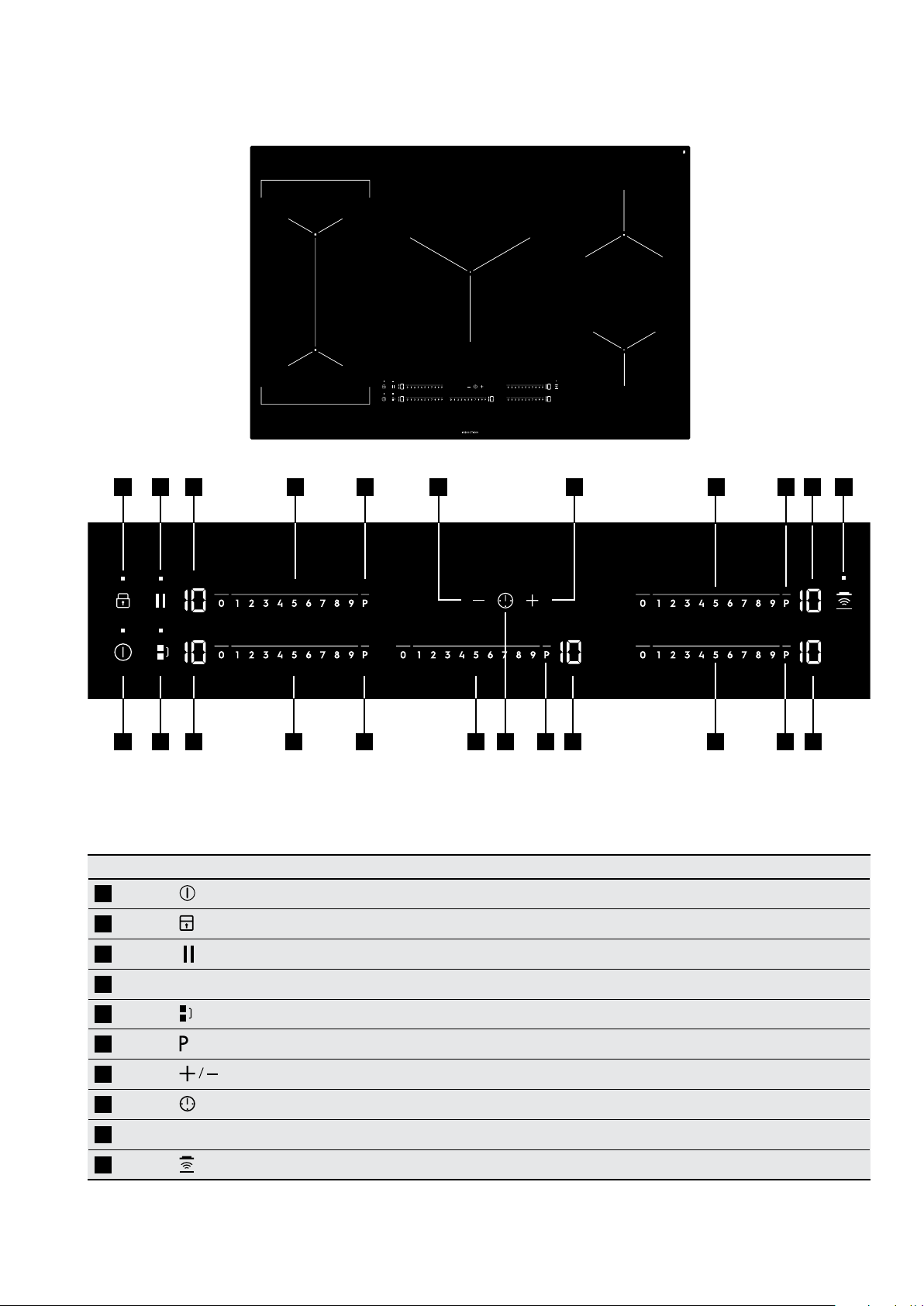
USING THE INDUCTION HOB
49
2 3 4 4
5
1
4 4 4
9 9
6 689 9 9
7 76 6
8
Use the sensor fields to operate the appliance. The displays, indicators and sounds tell which
functions operate.
Sensor field Function
1
2
Activates and deactivates the hob.
Locks and unlocks the control panel.
10
10
3
4
5
6
7
8
9
Heat setting display Indicates the selected heat setting.
Control bar Sets the heat setting.
Activates and deactivates the STOP + GO function.
Activates and deactivates the Bridge function.
Activates and deactivates the Power function.
Increases or decreases the time.
Sets the Timer functions.
Activates and deactivates the manual mode of the Hob2Hood function.
Page 50
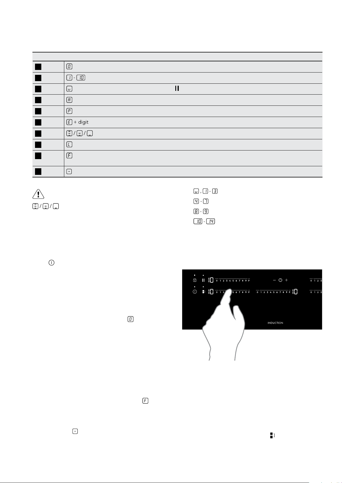
50 electrolux.com.au
USING THE INDUCTION HOB (CONTINUED)
Display Function
4
Indicates the cooking zone is deactivated.
4
4
4
4
4
4
4
4
Indicates the cooking zone is operated.
Indicates the function is operated.
Indicates the Automatic Heat Up function is operated.
Indicates the Power function is operated.
Indicates there is a malfunction (refer to malfunction list).
Indicates how much residual heat is left on a zone.
Indicates the Child Safety Lock is operated.
Indicates the use of incorrect cookware, too small or no cookware on the
cooking zone.
4
Indicates the Automatic Switch Off function has operated.
WARNING!
Risk of burns from residual heat!
The residual heat display indicates how much
heat is left on the ceramic glass when the zone is
deactivated. Use this display to help avoid the risk
of burns.
Activation and deactivation
Touc h
for 1 second to activate or deactivate the
appliance.
• - 6 hours
•
•
•
- 5 hours
- 4 hours
- 1.5 hours
The heat setting
To adjust the heat setting, place your finger over the heat
bar graphic and slide across. The display will show the
adjusted heat setting.
NOTE: When using cookware greater than 220mm the
manufacturer recommends that the centre zone be used.
Automatic switch off
THE APPLIANCE WILL AUTOMATICALLY SWITCH OFF IF:
• All cooking zones are deactivated (
).
• You do not set the heat setting after you activate the
appliance.
• You spill something or put something on the control
panel for more than 10 seconds (a pan, a cloth, etc).
An acoustic signal will sound and the appliance will
switch off. Remove the object or clean the control panel.
• The appliance becomes too hot (eg. when a
saucepan boils dry). Before you use the appliance
again, wait for the cooking zone to cool down.
• You use incorrect cookware. The symbol
will
come on and the cooking zone will deactivate
automatically after 2 minutes.
• A cooking zone is on for an extreme length of time.
The symbol
will show and the appliance will switch
off. See below.
• The length of time that various settings can run
for before automatic switch off occurs are
shown below:
NOTE: When you use cookware larger than 180mm the
manufacturer recommends that you put it on the rear
cooking zones.
Bridge function
The Bridge function connects two cooking zones together
and then operates them as one. You can use this function
for cookware larger than 260mm.
First set the heat setting for one of the cooking zones.
To activate the Bridge function touch
. The indicator will
then come on. To set or change the heat setting, touch
either one of the control sensors.
Page 51
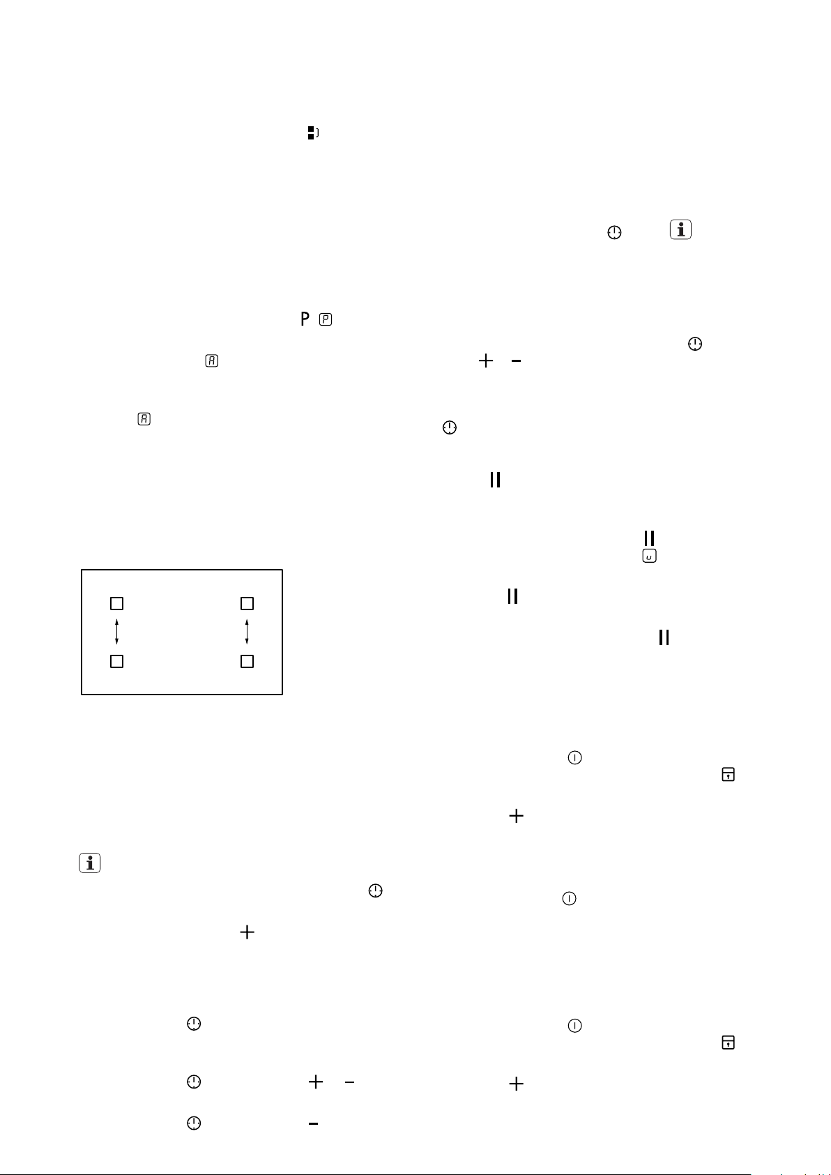
51
To deactivate the Bridge function touch . The
indicator will go off. The cooking zones will then operate
independently.
Fast heat up function
You can get a required heat setting in a shorter time if
you activate the Fast Heat Up function. This will run the
cooking zone at maximum until the required heat setting
is reached.
To start the Fast Heat Up function for a cooking zone:
1 Touch the power function sensor
( will come on).
2 Immediately touch your required heat setting.
After 3 seconds
comes on in the display.
3 The zone will heat at maximum until your required
heat setting is reached. The display will then change
from
back to the required heat setting.
4 To stop the Fast Heat Up function change the
heat setting.
Power management
Power management divides the power between the
front and rear zones for each of the 2 outer modules.
See illustration below:
counts down to 00. The timer indicator will go out.
When the timer count down comes to an end, the cooking
zone will deactivate, the 00 will flash and a beep sound
will occur for 20 seconds.
The beep sound and flashing can be deactivated
immediately by touching the
sensor. IMPORTANT!
When the two timer functions operate at the same time,
the display shows the count up timer first.
The Minute minder
You can use the timer as a minute minder when the
cooking zones are not in operation. Touch
. Then
touch or of the timer to set the time. When the timer
countdown comes to an end, 00 will flash and a beep
sound will occur for 30 seconds. The beep sound and
flashing can be deactivated immediately by touching the
sensor.
The Pause function
Use the
function to close down all of your operating
cooking zones to the lowest heat setting with just one
touch.
• To activate this function touch
. The indicator
will come on and the symbol will show on all
operating zones.
This allows either the front or rear zone to draw power
from the other, if maximum power is required.
The timer
The count down timer
Use the count down timer to set how long you want a
cooking zone to operate.
IMPORTANT!
• To select the cooking zone: touch the sensor
again
and again until the correct zone indicator is displayed.
• Immediately, touch the
sensor to set the time (00 99 minutes). When the timer indicator of the cooking
zone starts to flash more slowly the time will begin to
count down.
• To see the remaining time select the cooking
zone with the
sensor. The display will show the
remaining time.
• To change the count down timer: select the cooking
zone with the
sensor and touch or .
• To deactivate the count down timer select the cooking
zone with the
sensor and touch until the time
• When
is activated, you cannot change the heat
setting.
• To deactivate this function touch
again. The heat
setting that you set before comes back on.
Deactivating the beep sound
The beeping sound can be deactivated if required.
• First deactivate the hob.
• Then hold down
for 3 seconds. The displays will
come on and then go out. Then hold down for 3
seconds. 60 will now be displayed.
• Touc h
and change display to 61. The sound will
now be off.
• When the sound is deactivated you will still hear
sounds when:
5 You touch
.
6 You put something on the control panel.
7 The timer alert comes on.
To reactivate the sound
• First deactivate the hob.
• Then hold down
for 3 seconds. The displays will
come on and then go out. Then hold down for 3
seconds. 61 will now be displayed.
• Touc h
and change display to 60. The sound will
now be on.
Page 52

52 electrolux.com.au
USING THE INDUCTION HOB (CONTINUED)
Lock
Use this function to prevent an accidental change of the
heat settings.
• First set the heat setting.
• To start this function touch
. The symbol will then
show on all zones for 4 seconds before reverting back
to the heat settings.
• The indicator above the lock sensor will remain on.
• Timer functions will continue to operate after the lock
is activated.
• To stop this function touch
again. Deactivating the
appliance will also stop this function.
Child safety lock
Use this function to prevent an accidental operation
of the hob.
• To activate this function, first turn the hob on by
touching the
• Then hold down the
sensor.
sensor for 2 seconds. will
then show on all zones for 4 seconds before reverting
back to the heat setting.
• Turn the hob off by touching the
sensor again and
the hob is now in a mode where the heat settings
cannot be accidentally operated.
• To unlock, first turn the hob back on by touching the
sensor, and then hold down the sensor again.
Touc h again to switch off. This will bring the hob
back to normal operating mode.
Hob2Hood
This is an advanced automatic function which connects
the hob to a special hood. Both the hob and the hood
have an infra-red signal communicator. The speed of
the fan is defined automatically on the basis of the mode
setting and the temperature of the hottest cooking zone
on the hob. You can also operate the fan from the hob
manually.
IMPORTANT!
For most hoods, the remote system is originally
deactivated. Activate it before you use the function.
For more information refer to your hood user manual.
Automatic modes
Automatic
Boiling
1)
Frying
2)
light
Mode H0 Off Off Off
Mode H1 On Off Off
3)
Mode H2
On Fan speed 1 Fan speed 1
Mode H3 On Off Fan speed 1
Mode H4 On Fan speed 1 Fan speed 1
Mode H5 On Fan speed 1 Fan speed 2
Mode H6 On Fan speed 2 Fan speed 3
1. The hob detects the boiling process and activates
fan speed in accordance with automatic mode.
2. The hob detects the frying process and activates
fan speed in accordance with automatic mode.
3. This mode activates the fan and the light and does
not rely on the temperature.
Changing the automatic mode
1. Deactivate the appliance
2. To u ch
for 3 seconds. The display comes on
and goes off.
3. Touc h
4. Tou c h
5. Touc h
IMPORTANT!
for 3 seconds.
a few times until comes on.
of the Timer to select an automatic mode.
To operate the hood directly on the hood panel, deactivate
the automatic mode of the function.
When you finish cooking and deactivate the hob, the hood
fan may still operate for a certain period of time. After that
time the system deactivates the fan automatically and
prevents you from accidental activation of the fan for the
next 30 seconds.
Operating the function automatically
The default automatic mode from the factory is H5.
You can change the automatic mode by following the
instructions below. When you activate the job the hood
will adjust the fan speed automatically. Please note the
below table is a guide, the fan speed varies depending
on the temperature measured on the cooking zones of
the cooktop which can be affected by the heat setting(s)
selected as well as the size and volume of what you are
cooking.
Page 53

HELPFUL HINTS AND TIPS
IMPORTANT!
Induction cooking uses a strong electromagnetic
field to induce energy into the metal of the
cookware. This energy makes the cookware
become hot.
Cookware for induction cooking
IMPORTANT!
It is important to use cookware that is appropriate
for induction cooking. When purchasing cookware
always check the manufacturer’s specifications.
Cookware material
• Correct: cast iron, steel, enamelled steel,
stainless steel, the bottom made of multi-layer.
• Not correct: aluminium, copper, brass, glass,
ceramic, porcelain.
53
Cookware is correct for an induction hob if...
• some water boils very quickly on a zone set to the
highest heat setting.
• a magnet pulls on to the bottom of the cookware.
• The bottom of the cookware must be as thick and
flat as possible.
Use of the cooking zones
IMPORTANT
Always ensure the normal sized cookware is
centred over the crosses of the heating zones.
Extremely large cookware however cook on
two cooking zones at the same time.
ENVIRONMENT!
Energy saving
• If possible, always put the lids on the cookware.
• Put cookware on a cooking zone before you start it.
• Use the residual heat to keep the food warm
or to melt it.
• Do not use cookware where the base diameter
is smaller than 125mm.
Eco timer
Whenever the countdown timer is used the heat setting
will deactivate before the final countdown time is reached.
Residual heat left in the cookware will complete the final
stage of cooking and hence some energy is saved.
The difference in the operation time depends on the heat
setting level and the length of the cooking operation.
Page 54
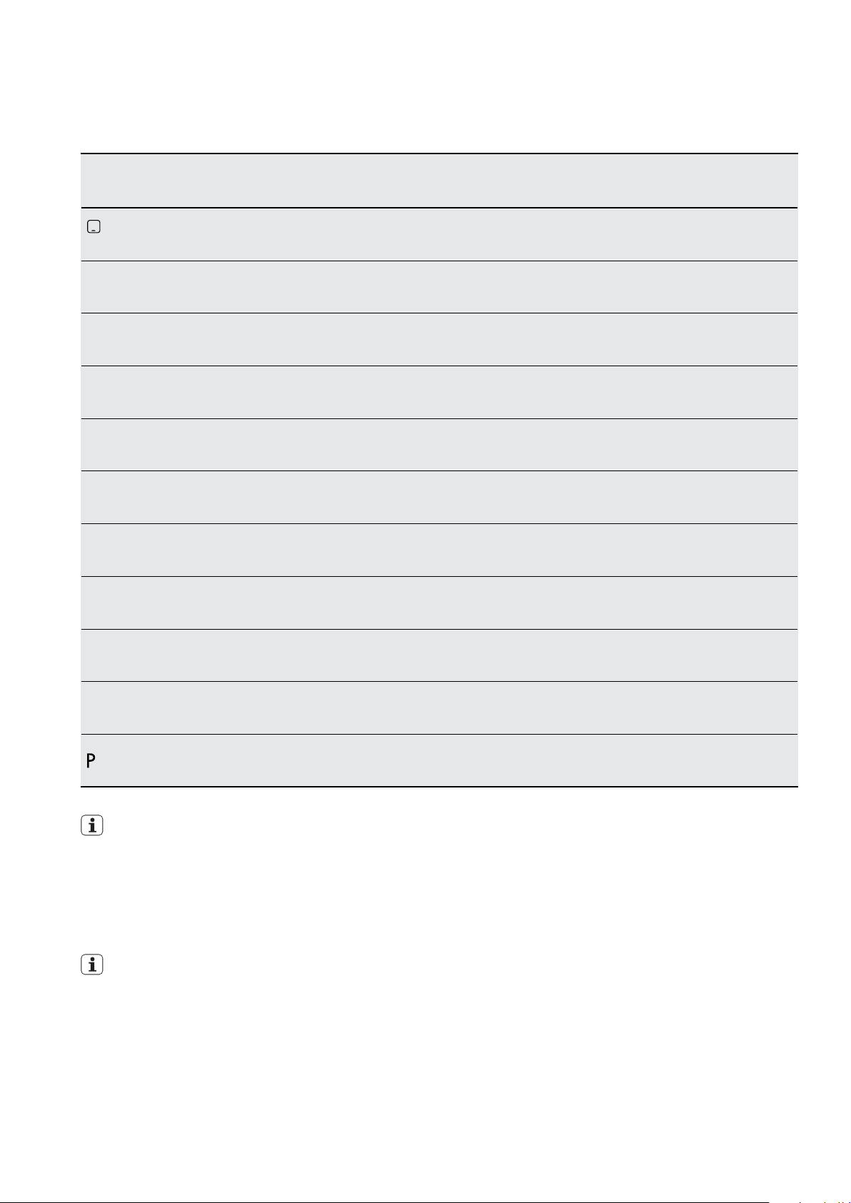
54 electrolux.com.au
USING THE INDUCTION HOB (CONTINUED)
Cooking guide
Heat
setting
1
1-3
1-3 Solidify: fluffy omelettes, baked eggs. 10-4 0 min Cook with a lid on. 3-8%
3-5
5-7 Steam vegetables, fish, meat. 20-45min
7-9 Steam potatoes. 20-60min
7-9
9-12
Use to: Time Hints
Keep warm. as required Place lid on cookware. 3%
Hollandaise sauce, melt: butter,
chocolate, gelatine.
Simmer rice and milk-based dishes,
heating up ready-cooked meals.
Cook larger quantities of food, stews
and soups.
Gentle fry: escalope, veal cordon bleu,
cutlets, rissoles, sausages, liver, roux,
eggs, pancakes, doughnuts.
5-25min Mix from time to time. 3-8%
Add twice as much liquid
25-50min
60 -150m i n
as necessary Turn halfway through. 25–45%
as rice, mix milk dishes
part way through.
Add a few tablespoons
of liquid.
Use max. of 1⁄4 litre of
water for 750g of potatoes.
Up to 3 litres of liquid plus
ingredients.
Nominal power
consumption
3-8%
13 -18%
18–25%
18–25%
12-13 Heavy fry, hash browns, loin steaks, steaks. 5-15 m in Turn halfway through. 45 – 64%
14
IMPORTANT!
Information on acrylamides
According to the newest scientific knowledge, if you brown
foods (especially those containing starch), acrylamides can
pose a health risk. Thus, we recommend that you cook at
the lowest temperatures and do not overly brown food.
IMPORTANT!
The data in the table is for guidance only.
Boil water, cook pasta, sear meat (goulash,
pot roast), deep fry chips.
Boil large quantities of water. Power
management is activated.
100%
Page 55
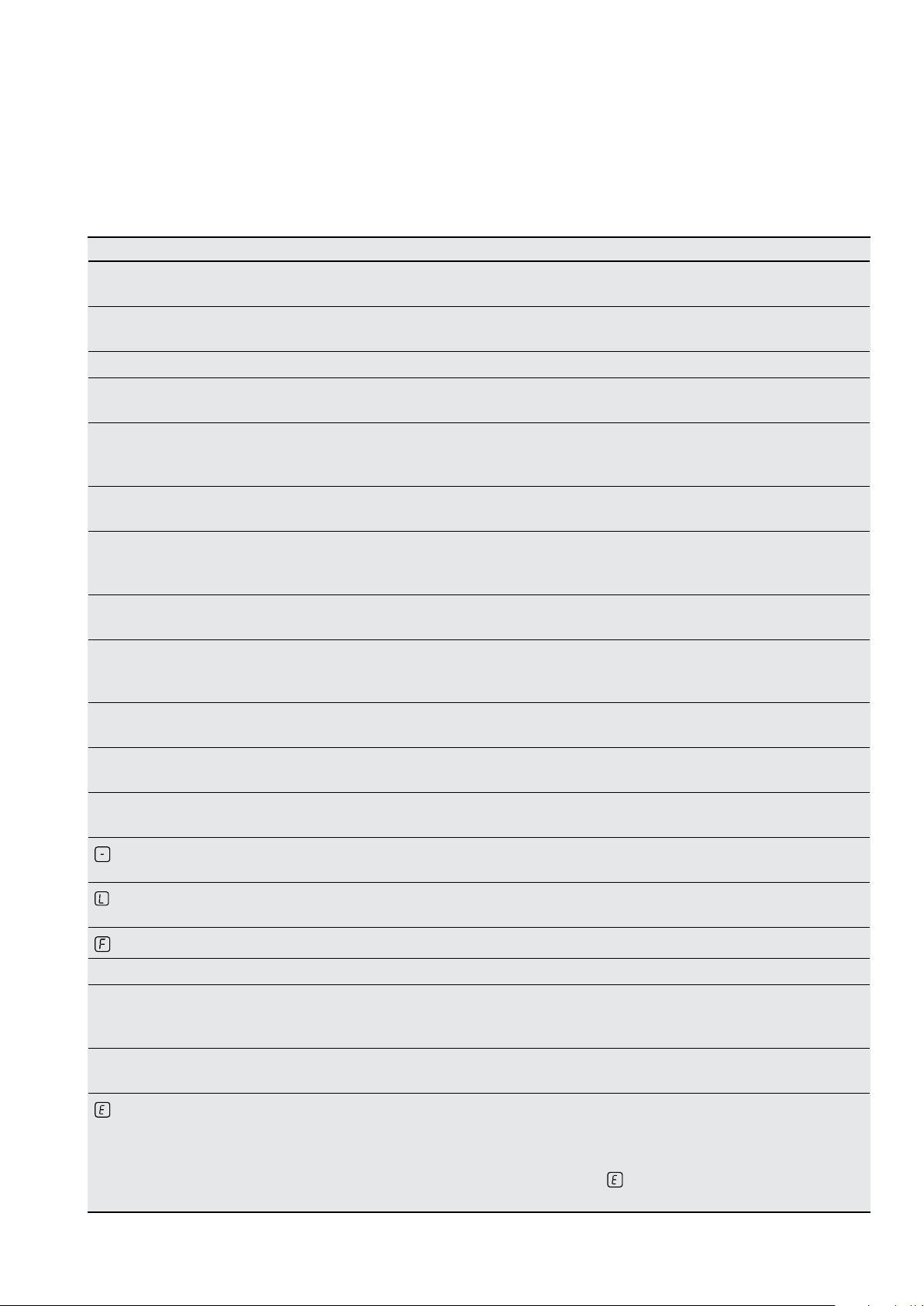
INDUCTION HOB TROUBLESHOOTING
If there is a problem with the appliance, please check the
points listed below before calling for service. It may be
possible to avoid a call by fixing the problem yourself and
be able to continue cooking.
Problem Possible cause Remedy
You cannot activate the appliance
or operate it.
You touched 2 or more sensor fields at
the same time.
The Stop+Go function is activated. Refer to Stop+Go instruction.
There is water or fat stains on the
control panel.
There is a beeping sound and
the cooktop switches off or the
cooktop may already be off.
The appliance deactivates. You have put something on the
The residual heat indicator does
not come on.
The Automatic Heat Up function
does not operate.
The heat setting changes between
two levels.
The sensor fields become hot. The cookware is too large or you put it
There is no signal when you touch
the panel sensor fields.
You have put someting on the control
panel sensor fields. This may occur
when cleaning the cooktop surface.
sensor field.
The cooking zone is not hot because it
operated only for a short time.
The cooking zone is already hot. Let the cooking zone become sufficiently
The highest heat setting is set. The highest heat setting has the
The Power management is activated. Refer to Power management instruction.
too near to the controls.
The signals are deactivated. Refer to the OffSound control instruction.
55
Activate the appliance again and set the
heat setting in less than 10 seconds.
Touch only one sensor field.
Clean the control panel.
Remove the object from the control panel
sensor fields. If the surface is wet, wipe
with a dry cloth.
Remove the object from the
sensor field.
If the cooking zone operated
sufficiently long to be hot, speak to
the service centre.
cool.
same power as the Automatic
Heat Up function.
Put large cookware on the rear cooking
zones if necessary.
comes on.
comes on.
comes on.
and a number comes on.
The Automatic Switch Off has
activated.
The Lock or Child safety lock function
is activated.
No cookware is on the cooking zone. Put cookware on the cooking zone.
The cookware is incorrect. Use correct cookware.
The diameter of the bottom of the
cookware is too small for the
cooking zone.
The cookware does not cover
the cross.
There is an error in the appliance. Disconnect the appliance from the
Deactivate the appliance and activate
it again.
Refer to the Lock and Child safety lock
instruction.
Use cookware that has a bottom
diameter greater than 125mm.
Cover the cross fully.
electrical supply for some time.
Disconnect the fuse from the electrical
system of the house. Connect it again.
comes on again, speak to the
If
service centre.
Page 56
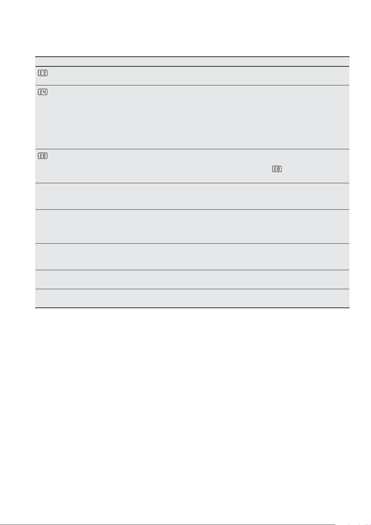
56 electrolux.com.au
INDUCTION HOB TROUBLESHOOTING (CONTINUED)
Problem Possible cause Remedy
comes on.
The electrical connection is incorrect.
The supply voltage is out of range.
Speak to a qualified electrician to check
the installation.
comes on.
comes on.
A crack noise can be heard. Can be caused by cookware made
A whistle sound can be heard. Can be caused by one or more
A humming sound can be heard. Can be caused by one or more
There is an error in the appliance
because a pot has boiled dry.
The overheating protection for the
cooking zone and the automatic
switch off has operated.
The electrical connection is incorrect.
One or more phases are missing.
of different materials (sandwich
construction).
cooking zones operating at high
power levels and the cookware made
of different materials.
cooking zones operating at high
power levels.
Deactivate the appliance. Remove the
hot cookware. After approximately 30
seconds, activate the cooking zone
again. If the cookware was the problem,
the error message will go out but the
residual heat indicator will stay. Check
to see if the cookware is appropriate for
induction cooking.
Have a qualified electrician check if the
installation is correct with the connection
illustration. If
to the service centre.
This is a normal noise from this style
of cookware.
This is a normal noise from this style
of cookware.
This is a normal noise and is not caused
by appliance malfunction.
comes on again, speak
A clicking sound can be heard. Can be caused by electrical switching
inside the unit.
A hissing and buzzing sound can
be heard.
Further information
When you need information, service or replacement parts
or have a warranty enquiry, please contact the Customer
Care Centre:
• Australia - 1300 363 640, 8.00am - 5.00pm
EST Monday to Friday
• New Zealand - 0800 436 245, 8.00am - 5.00pm
EST Monday to Friday
Please have the following information ready:
Model Number & Serial Number. This is shown on the data
plate which is visible when the oven door is open.
Can be caused by the fan operating
inside the unit.
This is a normal noise and is not caused
by appliance malfunction.
This is a normal noise and is not caused
by appliance malfunction.
Page 57
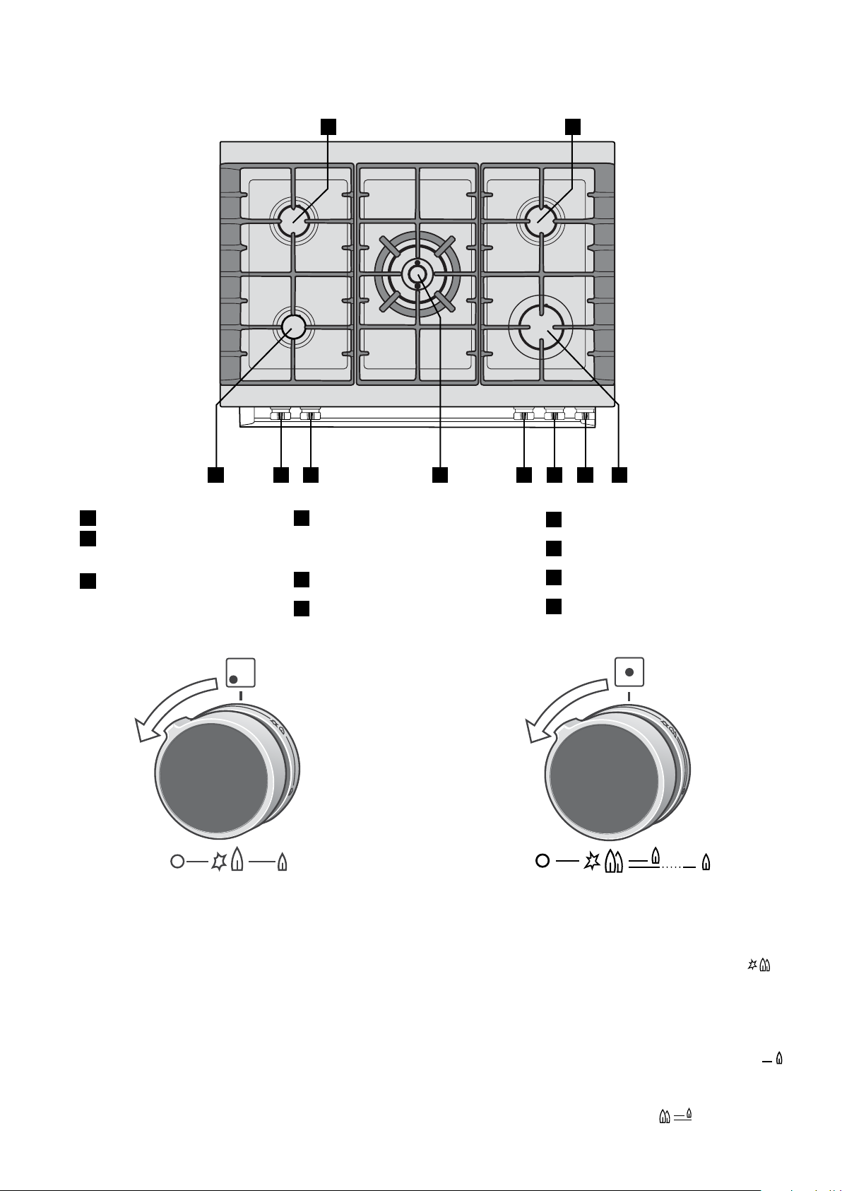
USING THE GAS HOB
57
21
3 5
1
9.0MJ/h Medium heat
burners. Used for simmering
2
with mid-sized cookware.
3
5.1MJ/h Low heat burner.
Used for simmering with
small cookware.
6 7 8 9 10
24.0 MJ/h dual valve wok burner.
4
4
7
Left hand front burner control.
Used for very fast heating with
8
Wok burner dual control.
woks and large cookware.
5
High heat burner.
6
Left hand rear burner control.
9
Right hand rear burner control.
10
Right hand front burner control.
Control knob for high, medium & low heat burners
To light a burner with this knob, firstly depress and turn
anti-clockwise to the ‘HI’ flame position. The knob may be
released after five seconds, once the flame is established
and turned further anti-clockwise to reduce the flame
height as desired.
NOTE: If the flame goes out when either knob is released,
turn the knob to OFF position, allow gas to disperse, then
try lighting again.
Control knob for the wok burner
To light the wok burner, depress the knob and turn
anti-clockwise to ignite the inner and outer burners
.
The knob may be released after five seconds, when both
inside and outside flames are established. Turning the
knob further anti-clockwise will reduce the height of the
outer flame.
Turning the knob further to the single flame/single line
will extinguish the outer flame and control the height of the
inner flame.
Turning the knob clockwise back to
will reignite the
outer flame.
Page 58

58 electrolux.com.au
GAS HOB TROUBLESHOOTING
If there is a problem with the appliance, please check the
points listed below before calling for service. It may be
possible to avoid a call by fixing the problem yourself and
be able to continue cooking.
Problem Possible cause Remedy
Burner will not light even though
the sparker is working.
No spark is obtained when
control knob is activated.
Flames uneven or tending to lift. Flame ports blocked or wet. Clean or dry flame ports.
Flames not staying on when
knob released.
Low heat, slow cooking. Incorrect cooking burner selection for the
Knob not held down long enough in ‘High’
position for flame safeguard to engage.
Gas supply valve turned off. Turn on gas supply to appliance.
Wrong knob turned off. Ensure the knob you are turning
Port blockage in ignition area. Ensure the ports in the ignition area are
Ignition spark plugs wet or dirty. Dry or clean ignition spark plugs.
Electricity supply is disconnected or
switched off.
Ignition spark plugs wet or dirty. Dry or clean ignition spark plugs.
Burner incorrectly fitted. Ensure this component is fitted correctly.
Knob not held down long enough in ‘High’
position for flame safeguard to engage.
Knob not set between ‘High’ and ‘Low’. Knob MUST be set between these
Dirt or spillage on flame safeguard sensor. Clean flameguard sensor tip.
size of pot being used.
Repeat lighting procedure and hold knob
down for 5 seconds in ‘High’ position.
corresponds to the burner you want
to light.
clean and dry.
Switch on electricity or check fuses.
Repeat lighting procedure and hold knob
down for 5 seconds in ‘High’ position.
positions.
Refer to page 36 for correct burner
selection.
Flame safeguard
The gas hob is fitted with a safety system that will stop
the flow of gas if for any reason the flame goes out
during operation. If this happens, the burner can be
restarted, but will require the knob to remain depressed
for approximately 5 seconds.
WARNING
• Keep hands clear of burners when lighting.
f burner does not ignite within 5 seconds, turn knob
• I
to ‘Off’ position, allow gas to disperse, then try lighting
again.
• Burners MUST be operated between ‘HIGH’
and ‘LOW’ settings only.
ENVIRONMENT!
To conserve gas, place the pan centrally over the burner
and adjust the flame so that it does not go past the edge
of the cookware.
NOTE: In the absence of electrical power, carry out
the ignition directly to the burner with a hand held
ignition source.
!
Further information
When you need information, service or replacement parts
or have a warranty enquiry, please contact the Customer
Care Centre:
• Australia - 1300 363 640, 8.00am-5.00pm
EST Monday to Friday
• New Zealand - 0800 436 245, 8.00am-5.00pm EST
Monday to Friday
Please have the following information ready: Model, Model
Number & Serial Number. This is shown on the data plate
which is visible when the oven door is open.
Page 59

CLEANING YOUR APPLIANCE
59
WARNING!
• Always make sure that the appliance is electrically
isolated before cleaning. This can be done by the
functional switch nearby.
• Do not line the bottom of the oven with foil
or cookware.
• Do not use steam cleaners.
Stainless steel parts
WARNING!
The oven door trim, the control panel trim and the
storage compartment are made from a special
stainless steel that resists finger marks and should
only be cleaned with warm water and a mild
detergent. Do not use stainless steel cleaners,
abrasive cleaners or harsh solvents on these parts.
NOTE: Make sure you follow the polish or brushing lines in
the stainless steel.
• All grades of stainless steel can stain, discolour or
become greasy. You must clean these regularly by
following the procedures below if you want your
appliance to look its best, perform well and have a
long life.
• Care must be taken when wiping exposed stainless
steel edges, they can be sharp!
• The stainless steel gas hob, side panels and kick
panel can be cleaned with stainless steel cleaners
if it becomes soiled or discoloured.
• A suitable cleaner can be purchased from Electrolux
Customer Care Centres.
• The glass edges have been specially ground to
remove any sharp edges. However it is glass, and
should be handled carefully to avoid injury to your
person and damage to the glass.
• Ensure glass panels are refitted to the door in the
same order and orientation they came out from.
Gas hob
• The trivets can be removed for cleaning by
carefully lifting them from the hob.
• Clean by washing with warm soapy water.
• The burner caps and crowns are also removable
for cleaning.
• If the caps, crowns and cups are heavily soiled,
use a non-abrasive cleaning compound.
• Flame port blockages should be removed by
using a matchstick or brush.
• Do not clean them with abrasive or caustic type
cleaners, or clean them in a dishwasher.
• The hob glass can be cleaned with a razor blade
scraper.
Induction hob
• Remove all spilt food and fat with the supplied razor
blade scraper, while the ceramic glass is still warm but
not hot. Wipe clean with dishwashing detergent on a
damp cloth.
• If aluminium foil, plastic items or high sugar content
foods are allowed to melt on the ceramic glass, clean
immediately with a razor blade scraper before the
surface has cooled down, otherwise pitting of the
surface can occur.
Oven door
• DO NOT use the oven without the inner and middle
door glass fitted.
• NEVER spray any caustic cleaners on any surface of
the door or damage to the surface coatings will result.
• DO NOT use metal utensils, scrapers, scourers, or
abrasive cleaners to clean the glass or any of the
door trims. These will damage or scratch the surface
coatings and degrade the finish and appearance.
• DO NOT place glass in dishwasher.
• Use only warm water and liquid detergent with a soft
cloth to clean the glass or trims.
• Before refitting the glass panes to the door ensure
they are dried with a soft cloth.
NOTE: Items with high sugar content not only include
jam and fruit, but also vegetables such as peas, tomatoes
and carrots.
• When the ceramic glass is cool, apply a suitable
ceramic glass cleaner.
• It is important to follow the cleaner manufacturer’s
instructions. Remove any cleaning residue from the
surface as staining of the cooktop may occur.
• Do not use abrasive sponges or scourers, as they
may scratch the surface.
• Any pitting, staining, scratches or other surface
deterioration is excluded from the warranty.
• Sometimes SURFACE stains appear to be ‘bubble’
marks under the ceramic glass. These can be cleaned
off with a razor blade scraper and ceramic cleaner.
Page 60
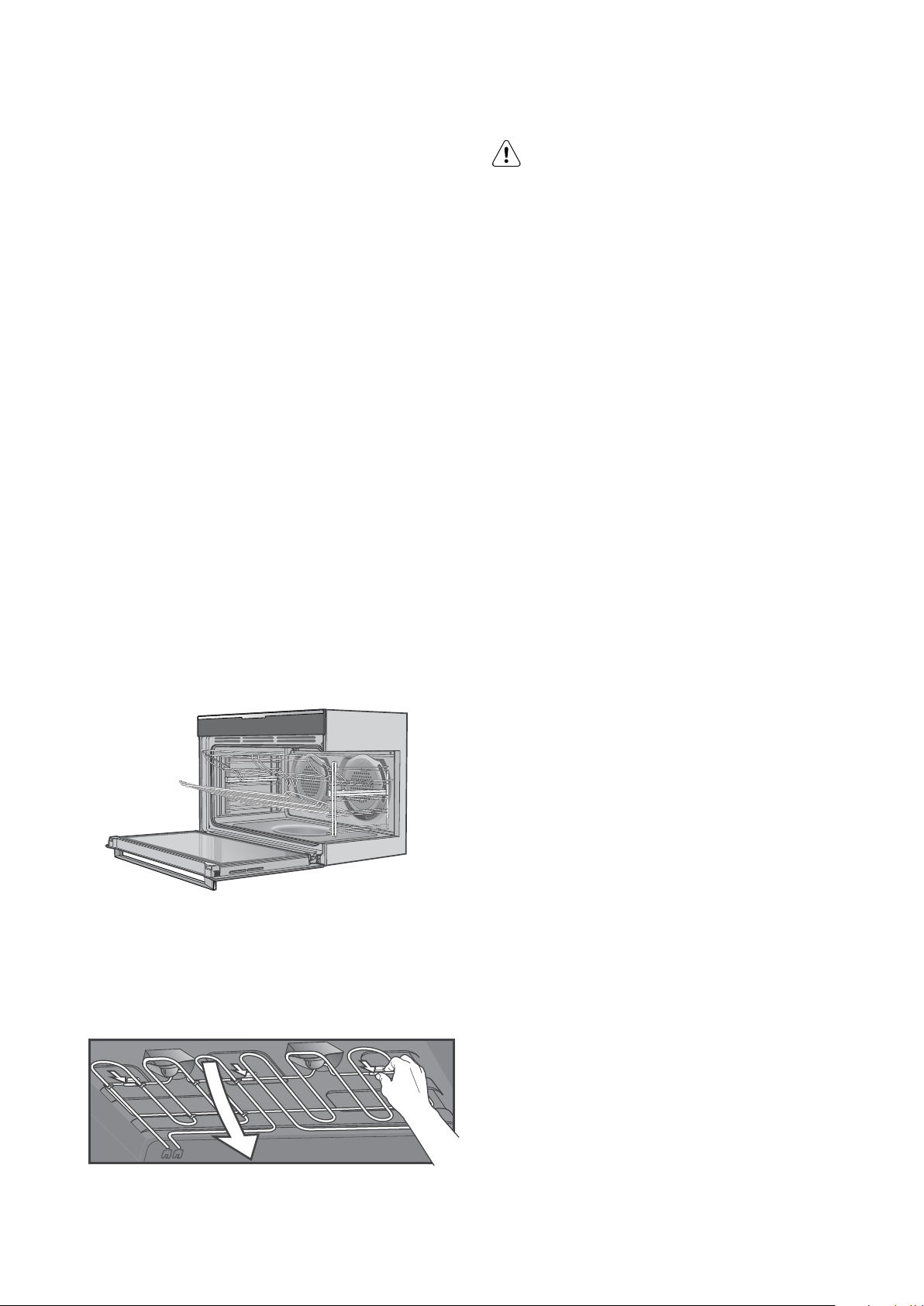
60 electrolux.com.au
CLEANING YOUR APPLIANCE (CONTINUED)
Oven
• Always keep your appliance clean. Ensure that fats
and oils do not accumulate around elements or fans.
• Always keep the oven dish, baking trays, grill dish
and grill dish inserts clean, as any fat deposits may
catch fire.
• Always wrap your meats in foil or an oven roasting
bag to minimise cleaning. Any polyunsaturated fats
can leave a varnish-like residue which is very difficult
to remove.
Grill
• Always keep the grill dish and grill dish insert clean,
as any fat deposits may catch fire.
Removing the shelves and grill dishes
• Slide the shelves and grill dish carrier towards you
until they reach the front stop.
• Tilt them up at the front to clear the side supports,
taking care not to spill the contents.
• Lift them clear.
• Wash the shelves and grill dish in hot soapy water.
WARNING
The door glass on this appliance is made from a
tough, durable material that withstands heating
and cooling without breaking. However, it must be
remembered that it is GLASS, it may break. Treat it
accordingly! Should you have any questions about
the glass in your new appliance, please contact the
customer care centre by dialling 1300 363 640.
Do not use harsh abrasive cleaners or sharp metal
scrapers to clean the oven door since they can
scratch the surface, which may result in shattering
of the glass.
• Reverse the above steps to put the shelves and grill
dishes back again.
• Ensure that they are placed between the 2 support
wires or correctly onto the runners.
Releasing the grill element
To release the grill element so that the oven roof can be
accessed for cleaning, push the element upwards and
rotate the 3 clips backwards and away from the element
rod. This will allow the front of the element to drop down.
Page 61

61
CLEANING YOUR APPLIANCE WITH PYROLYTIC CLEANING
Cleaning Reminder
After a recommended period of time the oven will remind
you to clean the oven. Once this period of time has
elapsed, when turning the oven off you will get a message
“TIME TO CLEAN YOUR OVEN”. Press the on/off button
to clear the message and run the Pyrolitic cycle. After the
Pyrolitic cycle has finished, the cleaning reminder will reset.
The “Cleaning Reminder” setting can be enabled/disabled
in the settings menu.
Alternatively while the “TIME TO CLEAN YOUR OVEN”
message is displayed, you can press the “ok” button and
you will get the option to “REMIND ME AGAIN”.
Pyrolytic cleaning of the oven cavity
The oven has the Pyrolytic self-cleaning function, it
cleans by burning off the spatters and accumulated
dirt and grease from the oven liner, at high temperature.
This process produces ash which can then be wiped
out of the oven cavity.
Pyrolytic cleaning will not remove limestone residue
left in the cavity well when water evaporates. It is
recommended that the residue is cleaned prior to
conducting Pyrolytic cleaning cycles. See ‘Cleaning
the cavity well’ on this page.
4 Choose your Pyrolytic cleaning cycle from
the following:
Submenu Application
Quick Duration: 1 hour 30 minutes
Normal Duration: 2 hours
Intense Duration: 2 hours 30 minutes
NOTE: Duration includes heat-up time, excludes cooldown time.
Light clean
This is an energy saving cycle that can be used on a
regular basis if the oven is lightly soiled. Possibly after
every 2nd or 3rd roast.
Medium clean
Use this as the regular cycle about once every 2-3
months.
Heavy clean
When the oven is very dirty it may need a longer cycle to
clean it thoroughly. This cycle will clean the dirtiest of ovens.
WARNING!
During the pyrolytic cleaning process the oven
becomes extremely hot.
DO NOT use Hob during Pyrolytic cleaning
• Please keep small children at a safe distance.
• Never clean non-stick baking trays and tins in the
oven during the pyrolytic cycle. High temperatures
damage the non-stick coating and poisonous gas is
released.
• To prevent damage, do not use acids, sprays or
similar cleaning agents.
CAUTION!
• During pyrolytic cleaning the air outlet exhaust
above the door must be kept clear of any
obstruction (e.g. bulky tea towels).
• Do not use your oven to clean miscellaneous
items (e.g. cookware).
WARNING!
Before carrying out the Pyrolytic function
1 All accessories must be removed from the
oven, including shelves, trays and side racks.
2 Clean large deposits, spills or grease from
the oven cavity.
3 Clean limestone residue from the cavity well.
Food Probe
Clean the Food Probe after each use and let it dry. Use
a soft cloth with warm water and a cleaning agent. Only
clean the probe end and not the plug.
Cleaning the cavity well
The cleaning procedure removes limestone residue from
the cavity well after cooking with steam.
WARNING!
Perform the cleaning procedure at least every
5-10 Bake + Steam cooking cycles.
1 Mix 200ml of tap water with 150ml of white
vinegar and put the mix in the cavity well.
2 Let the water and vinegar mix dissolve the
limestone residue at the ambient temperature
for 45 minutes.
3 Remove the water and vinegar mix with a soft
cloth and clean the cavity with warm water and
a soft cloth.
NOTE: Pyrolytic cleaning cycle does not clean left over
salts from evaporation. Please use the following procedure
to clean the cavity well.
The oven should be reasonably dry before using the
Pyrolytic clean function.
NOTE: Side racks and slides do not need to be removed to
run the pyrolytic function.
Page 62

62 electrolux.com.au
CLEANING YOUR APPLIANCE WITH PYROLYTIC
CLEANING (CONTINUED)
IMPORTANT
At the beginning of Pyrolytic cleaning the door will
automatically lock and the
display. During the Pyrolytic cleaning cycle there
may be some burn off odours. It is advised to keep
the room well ventilated during this cycle.
The door will only unlock when the oven has cooled to a
safe temperature. Turning the function off will not unlock
the door. This will only happen when safe temperatures
are reached.
When the pyrolytic cleaning function is on, it is advisable
not to use a cooktop. This may cause overheating and
damage.
NOTE: The cooling fan will operate at an increased speed
for Pyrolytic cleaning and will continue to run until the oven
has cooled down. This is normal.
will appear on the
It is recommended to clean the oven regularly to keep it in
its best condition.
After Pyrolytic cleaning
After cool-down wipe the ash out of the oven with a soft
damp cloth and warm water.
To restore the enamel shine to more difficult areas, use a
damp cloth with vinegar and detergent.
CAUTION
Do not turn off the mains power supply to the
oven during the Pyrolytic cycle. This could damage
the appliance.
Page 63
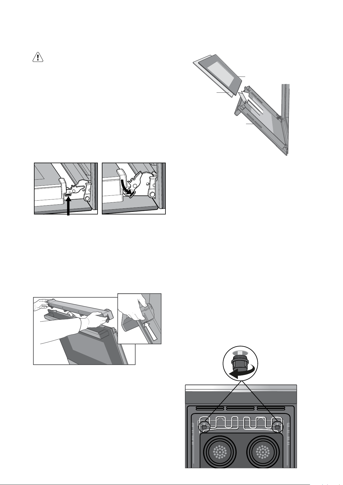
CLEANING THE OVEN DOOR
WARNING
Slides (telescopic runners)
• Do not place slides in a dishwasher.
63
Inner Glass
• Do not use a knife or sharp objects to
clean slides.
• Do not add oil or any other lubricant to slides.
Positioning the door for dismantling
The door needs to be positioned at an angle to aid in
the disassembly of the panes.
• Open the door fully to gain access to the hinges.
• Push down the hinge locking tab on both hinges.
Locking tab up - normal position Locking tab down - for cleaning
• Gently close the door until it stops in the partially
open position on the locking tab.
NOTE: The door cannot fully close with the locking tab
in this down position.
Removing the top door trim
• Push in the 2 tabs on either side of the trim.
• Lift the trim away from the door.
Middle G lass x 2
Outside_
Reassembling the glass panes & and top door trim
• Replace the middle glass back to the door first.
The middle glass is a clear pane and orientation of
the glass is not important.
• Replace the inner glass next ensuring the side that
is painted is facing away from the oven cavity.
• Replace the top door trim ensuring the 2 side tabs
have clipped into the column.
• Pull the hinge locking tabs back up and close the door.
Changing the light globes
• Switch the appliance off at the isolation switch before
attempting to change the light globe.
• There are 2 light globes located in the top of the oven
cavity towards the rear.
• To get access to the globes, firstly drop the element
down as explained on page 41.
• To remove, turn oven light glass anti-clockwise.
• A special high temperature resistant borosilicate globe
should be used. This can be purchased from the
Customer Care Centre.
Removing the glass panes
• Remove the inner glass and middle glass layers
from the door.
• Clean the glass using detergent and warm water.
Wipe clean and dry thoroughly.
• The outside glass cannot be removed from the
door and hence can be cleaned in-situ.
Light glass can be removed
- turn anti-clockwise
Page 64
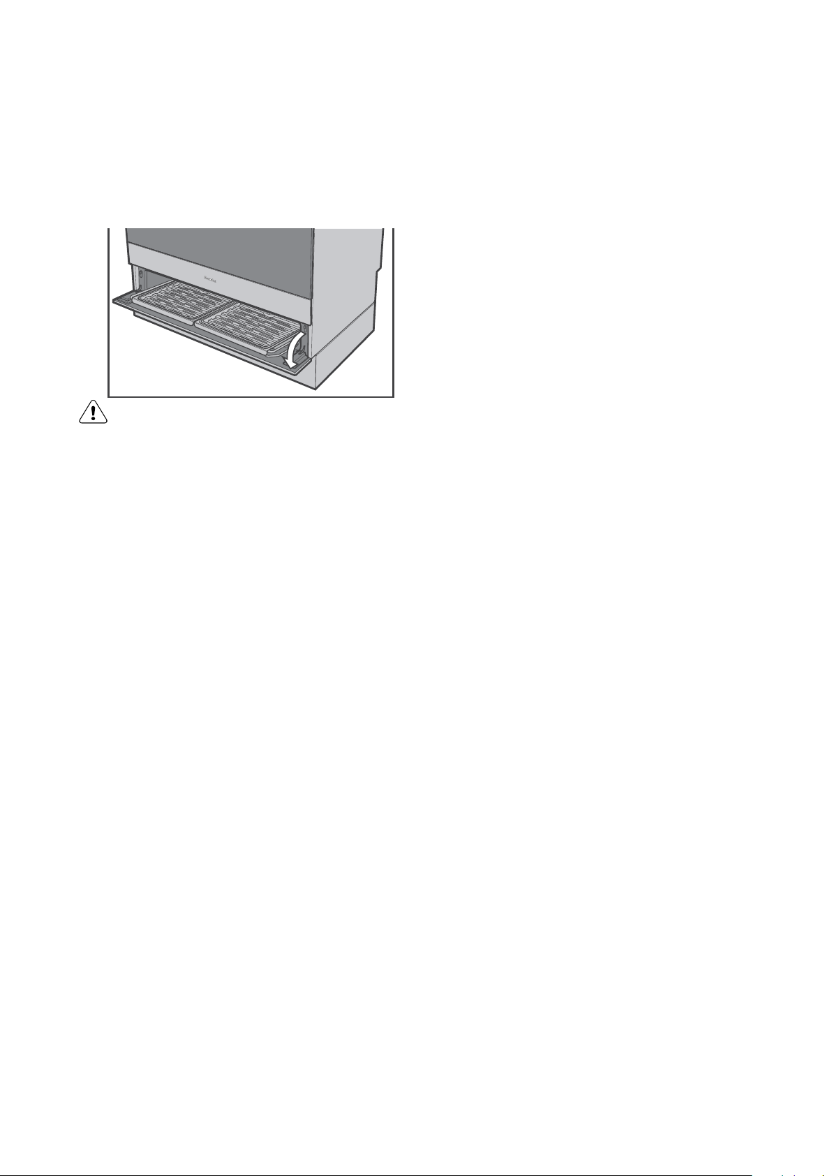
64 electrolux.com.au
CLEANING THE OVEN DOOR (CONTINUED)
Storage compartment (selected models)
The storage compartment is accessible through the
pivoting door.
Unused oven racks and grill dishes can be stored here.
WARNING!
DO NOT store flammable or combustible items
in the storage compartments. This is not a
compartment for warming food.
Page 65

NOTES
65
Page 66

66 electrolux.com.au
NOTES
Page 67

Warranty
FOR SALES IN AUSTRALIA AND NEW ZEALAND
APPLIANCE: ELECTROLUX BUILT-IN OVENS, COOKTOPS,
FREESTANDING COOKER AND WARMING DRAWER
This document sets out the terms and conditions of the product
warranties for Electrolux Appliances. It is an important document.
Please keep it with your proof of purchase documents in a safe place
for future reference should there be a manufacturing defect in your
Appliance. This warranty is in addition to other rights you may have
under the Australian Consumer Law.
1. In this warranty:
(a) ‘ACL’ or ‘Australian Consumer Law’ means Schedule 2 to the
Competition and Consumer Act 2010;
(b) ‘Appliance’ means any Electrolux product purchased by you and
accompanied by this document;
(c) ‘ASC’ means Electrolux’s authorised serviced centres;
(d) ‘Electrolux’ is the brand controlled by Electrolux Home Products Pty
Ltd of 163 O’Riordan Street, Mascot NSW 2020, ABN 51 004 762
341 in respect of Appliances purchased in Australia and Electrolux
(NZ) Limited (collectively “Electrolux”) of 3-5 Niall Burgess Road, Mount
Wellington, in respect of Appliances purchased in New Zealand;
(e) ‘WarrantyPeriod’meanstheperiodspeciedinclause3ofthis
warranty;
(f) ‘you’ means the purchaser of the Appliance not having purchased
the Appliance for re-sale, and ‘your’ has a corresponding meaning.
2. Application: This warranty only applies to new Appliances, purchased
and used in Australia or New Zealand and is in addition to (and does not
exclude, restrict, or modify in any way) other rights and remedies under
a law to which the Appliances or services relate, including any nonexcludable statutory guarantees in Australia and New Zealand.
3. Warranty Period: Subject to these terms and conditions, this warranty
continues in Australia for a period of 24 months and in New Zealand
for a period of 24 months, following the date of original purchase of the
Appliance.
4. Repair or replace warranty: During the Warranty Period, Electrolux
or its ASC will, at no extra charge if your Appliance is readily accessible
for service, without special equipment and subject to these terms and
conditions, repair or replace any parts which it considers to be defective.
Electrolux may, in its absolute discretion, choose whether the remedy
oeredforavalidwarrantyclaimisrepairorreplacement.Electroluxorits
ASC may use refurbished parts to repair your Appliance. You agree that
any replaced Appliances or parts become the property of Electrolux.
5. Travel and transportation costs: Subject to clause 7, Electrolux will
bear the reasonable cost of transportation, travel and delivery of the
Appliance to and from Electrolux or its ASC. Travel and transportation
will be arranged by Electrolux as part of any valid warranty claim.
6. Proof of purchase is required before you can make a claim under this
warranty.
7. Exclusions: You may not make a claim under this warranty unless
the defect claimed is due to faulty or defective parts or workmanship.
This warranty does not cover:
(a) lightglobes,batteries,ltersorsimilarperishableparts;
(b) parts and Appliances not supplied by Electrolux;
(c) cosmeticdamagewhichdoesnotaecttheoperationofthe
Appliance;
(d) damage to the Appliance caused by:
(i) negligence or accident;
(ii) misuse or abuse, including failure to properly maintain or service;
(iii) improper, negligent or faulty servicing or repair works done by
anyone other than an Electrolux authorised repairer or ASC;
(iv) normal wear and tear;
(v) power surges, electrical storm damage or incorrect power supply;
(vi) incomplete or improper installation;
(vii) incorrect, improper or inappropriate operation;
(viii) insect or vermin infestation;
(ix) failure to comply with any additional instructions supplied with
the Appliance;
In addition, Electrolux is not liable under this warranty if:
(a) the Appliance has been, or Electrolux reasonably believes that the
Appliance has been, used for purposes other than those for which
the Appliance was intended, including where the Appliance has
been used for any non-domestic purpose;
(b) theApplianceismodiedwithoutauthorityfromElectroluxinwriting;
(c) the Appliance’s serial number or warranty seal has been removed
or defaced
8. How to claim under this warranty: To enquire about claiming under
this warranty, please follow these steps:
(a) carefully check the operating instructions, user manual and the terms
of this warranty;
(b) have the model and serial number of the Appliance available;
(c) have the proof of purchase (e.g. an invoice) available;
(d) telephone the numbers shown below.
9. Australia: For Appliances and services provided by Electrolux in
Australia: Electrolux goods come with guarantees that cannot be
excluded under the Australian Consumer Law. You are entitled to a
replacement or refund for a major failure and for compensation for any
other reasonably foreseeable loss or damage. You are also entitled to
have the Appliance repaired or replaced if the Appliance fails to be of
acceptable quality and the failure does not amount to a major failure.
‘Acceptable quality’ and ‘major failure’ have the same meaning as
referred to in the ACL.
10. New Zealand: For Appliances and services provided by Electrolux
in New Zealand, the Appliances come with a guarantee by Electrolux
pursuant to the provisions of the Consumer Guarantees Act, the Sale
of Goods Act and the Fair Trading Act. Where the Appliance was
purchased in New Zealand for commercial purposes the Consumer
Guarantee Act does not apply.
11.Condentiality: You accept that if you make a warranty claim, Electrolux
and its agents including ASC may exchange information in relation to you
to enable Electrolux to meet its obligations under this warranty.
Before calling for service, please ensure that the steps listed in clause 8 above have been followed.
NEW ZEALAND
ECook_Warr_Jul19
AUSTRALIA
Important Notice
FOR SERVICE
ortondtheaddressofyournearest
authorised service centre in Australia
PLEASE CALL 13 13 49
For the cost of a local call
FOR SERVICE
ortondtheaddressofyournearest
authorised service centre in New Zealand
PLEASE CALL 0800 10 66 10
FOR SPARE PARTS
ortondtheaddressofyournearest
spare parts centre in Australia
PLEASE CALL 13 13 50
For the cost of a local call
FOR SPARE PARTS
ortondtheaddressofyournearest
spare parts centre in New Zealand
PLEASE CALL 0800 10 66 20
Page 68
Electrolux Home Products Australia
telephone: 13 13 49
email: [email protected]
web: electrolux.com.au
Electrolux Home Products New Zealand
telephone: 0800 10 66 10
email: [email protected]
web: electrolux.co.nz
To add a touch of
professional inspiration
to your home, visit
electrolux.com.au
or electrolux.co.nz
shop.electrolux.com.au
electrolux.com.au
or electrolux.co.nz
P/No. A19347301 Rev:01
ECN: 119592
© 2022 Electrolux Home Products Pty Ltd.
E_MAN_90cm_Cooker_Feb22
 Loading...