

Page 1

USER MANUAL
EFC6620
EFC9620
Page 2

Page 3
electrolux 3
RECOMMENDATIONS AND SUGGESTIONS
6
CHARACTERISTICS 7
INSTALLATION 9
USE 11
MAINTENANCE 13
EN
EMPFEHLUNGEN UND HINWEISE 15
CHARAKTERISTIKEN 16
MONTAGE 18
BEDIENUNG 20
WARTUNG 22
CONSEJOS Y SUGERENCIAS 24
CARACTERÍSTICAS 25
INSTALACIÓN 27
USO 29
MANTENIMIENTO 31
CONSELHOS E SUGESTÕES 33
CARACTERÍSTICAS 34
INSTALAÇÃO 36
UTILIZAÇÃO 38
MANUTENÇÃO 40
TAVSIYELER VE ÖNERILER 42
ÖZELLIKLER 43
MONTAJ 45
KULLANIM 47
BAKIM 49
CONSIGLI E SUGGERIMENTI 51
CARATTERISTICHE 52
INSTALLAZIONE 54
USO 56
MANUTENZIONE 58
DE
ES PT
TR IT
Page 4
4 electrolux
Welcome to the world of Electrolux
Thank you for choosing a fi rst class
product from Electrolux, which hopefully will provide you with lots of pleasure
in the future. The Electrolux ambition is
to offer a wide variety of quality products that make your life more comfortable. You fi nd some examples on the
cover in this manual. Please take a few
minutes to study this manual so that
you can take advantage of the benefi ts
of your new machine. We promise that
it will provide a superior User Experience delivering Ease-of-Mind.
Good luck!
EN
Willkommen bei Electrolux!
Wir möchten uns bedanken, dass Sie
sich für ein erstklassiges Produkt von
Electrolux entschieden haben, welches
Ihnen sicherlich viel Freude bereiten
wird. Es ist unser Bestreben, eine breite
Vielfalt von Qualitätsprodukten anzubieten, die helfen, Ihr Leben etwas komfortabler zu machen. Sie fi nden einige
Beispiele auf der vorletzten Seite in diesem Heft. Bitte nehmen Sie sich einige
Minuten, diese Benutzerinformation zu
lesen, um voll von den Vorteilen Ihres
neuen Gerätes profi tieren zu können.
Wir sind sicher, dass wird Ihr Leben
zukünftig etwas leichter machen.
Wir wünschen eine gute Zeit.
DE
ES PT
Bienvenido al mundo Electrolux
Gracias por elegir un producto Electrolux de primera clase, el cual esperamos
le proporcione una gran satisfacción en
el futuro. Electrolux ambiciona ofrecerle
una amplia variedad de productos de
calidad que haga su vida más cómoda.
Usted encontrará algunos ejemplos en
la portada de este manual. Por favor,
tómese unos minutos para estudiar
este manual de modo que pueda
aprovecharse de los benefi cios de su
nueva máquina. Nosotros prometemos
proporcionarle una experiencia superior
como usuario y mucha tranquilidad.
¡Buena suerte!
Bem-vindo ao mundo Electrolux
Obrigado por ter escolhido adquirir um
produto de primeira classe da Electrolux, que esperamos lhe traga muito
prazer no futuro. A ambição da Electrolux é oferecer uma vasta variedade de
produtos de qualidade que tornem a
sua vida ainda mais confortável. Pode
encontrar alguns exemplos na capa
deste manual. Tire alguns minutos para
estudar este manual para que possa
começar a tirar partido dos benefícios
do seu novo aparelho. Nós prometemos que lhe irá proporcionar uma experiência superior e confortante como
utilizador.
Boa sorte!
Page 5

electrolux 5
Electrolux dünyasına hoșgeldiniz
Size kullanımı boyunca memnuniyet
vereceğini umduğumuz birinci sınıf
bir Electrolux ürünü seçtiğiniz için
teșekkür ederiz. Electrolux, hayatınızı
daha da konforlu hale getirecek
kaliteli ürünlerden olușan geniș bir
ürün yelpazesi sunmayı hedefl er.
Kılavuzunuzun kapağında bu
ürünlerden bazı örnekler bulabilirsiniz.
Yeni makinenizin özelliklerinden tümüyle
yararlanabilmeniz için birkaç dakikanızı
ayırıp, kılavuzunuzu okumanızı öneririz.
Bunun size hayatınızı kolaylaștıracak
mükemmel bir kullanım rahatlığı
sağlayacağına söz veriyoruz. İyi șanslar
TR
Egregio Cliente,
complimenti per aver scelto un elettrodomestico Electrolux che, siamo
certi, avrà modo di apprezzare per le
prestazioni, la qualità e l’affi dabilità e
che le renderà la vita di ogni giorno più
confortevole, facile e sicura.
Da sempre il nostro impegno è quello
di produrre utilizzando la tecnologia più
avanzata, nel rispetto dell’ambiente e
sempre in anticipo rispetto agli obblighi
normativi.
Oltre il 90% dei nostri elettrodomestici
sono prodotti ecologici in classe A,
A+, A++ e vengono raccomandati dal
WWF.
La lettura completa di questo libretto le
permetterà un utilizzo corretto e sicuro
della sua apparecchiatura e le darà
anche utili consigli sulla manutenzione
più effi ciente.
IT
Page 6
6 electrolux Recommendations and Suggestions
EN
Installation
• The manufacturer will not be held li-
able for any damages resulting from
incorrect or improper installation.
• The minimum safety distance be-
tween the cooker top and the extractor hood is 650 mm.
• Check that the mains voltage corre-
sponds to that indicated on the rating
plate fi xed to the inside of the hood.
• For Class I appliances, check that the
domestic power supply guarantees
adequate earthing.
Connect the extractor to the exhaust
fl ue through a pipe of minimum diameter 120 mm. The route of the fl ue
must be as short as possible.
• Do not connect the extractor hood to
exhaust ducts carrying combustion
fumes (boilers, fi replaces, etc.).
• If the extractor is used in conjunction
with non-electrical appliances (e.g.
gas burning appliances), a suffi cient
degree of aeration must be guaranteed in the room in order to prevent
the backfl ow of exhaust gas. The
kitchen must have an opening communicating directly with the open air in
order to guarantee the entry of clean
air.
Use
• The extractor hood has been de-
signed exclusively for domestic use to
eliminate kitchen smells.
• Never use the hood for purposes
other than for which it has ben designed.
• Never leave high naked fl ames under
the hood when it is in operation.
• Adjust the fl ame intensity to direct it
onto the bottom of the pan only, making sure that it does not engulf the
sides.
• Deep fat fryers must be continuously
monitored during use: overheated oil
can burst into fl ames.
• Do not fl ambè under the range hood;
risk of fi re
• The hood should not be used by children or persons not instructed in its
correct use.
Maintenance
• Switch off or unplug the appliance
from the mains supply before carrying
out any maintenance work.
• Clean and/or replace the Filters after
the specifi ed time period.
• Clean the hood using a damp cloth
and a neutral liquid detergent.
The symbol on the product or on its
packaging indicates that this product may
not be treated as household waste. Instead
it shall be handed over to the applicable
collection point for the recycling of electrical
and electronic equipment. By ensuring this
product is disposed of correctly, you will help
prevent potential negative consequences for
the environment and human health, which
could otherwise be caused by inappropriate
waste handling of this product. For more
detailed information about recycling of this
product, please contact your local city offi ce,
your household waste disposal service or
the shop where you purchased the product.
RECOMMENDATIONS AND SUGGESTIONS
Page 7
Characteristics electrolux 7
EN
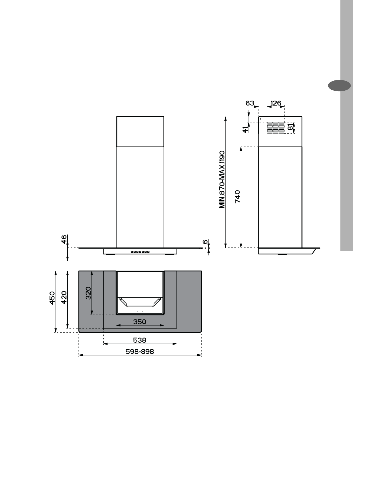
Dimensions
CHARACTERISTICS
Page 8
8 electrolux Characteristics
EN
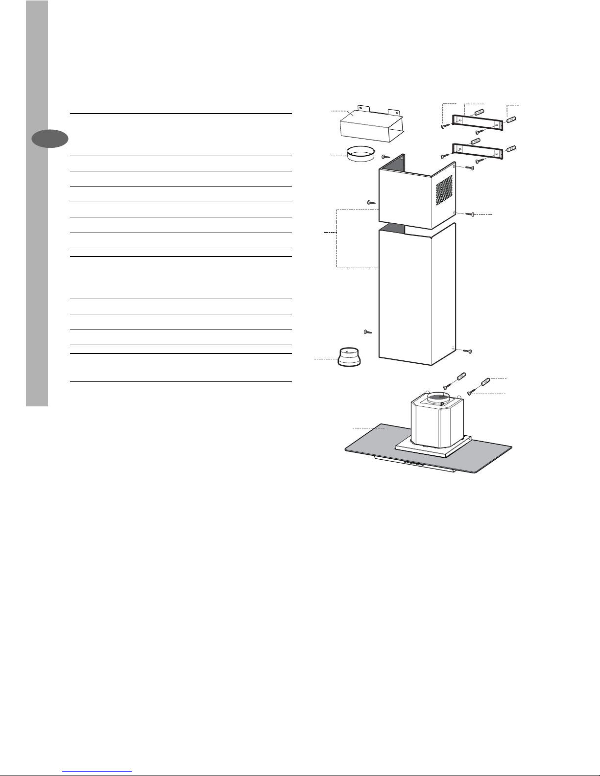
Components
Ref. Q.ty Product Components
1 1 Hood Body, with: Controls, Light,
Blower, Filters
2 1 Telescopic Chimney:
2.1 1 Upper Section
2.2 1 Lower Section
9 1 Reducer Flange ø 150-120 mm
10 1 Flange ø 150
15 1 Air Outlet Connection
Ref. Q.ty Installation Components
7.2.1 2 Upper Chimney Section Fixing
Brackets
11 6 Wall Plugs
12a 6 Screws 4,2 x 44,4
12c 6 Screws 2,9 x 9,5
Q.ty Documentation
1 Instruction Manual
2.1
2.2
2
12c
12a
7.2.1 11
11
12a
1
9
10
15
Page 9
Installation electrolux 9
EN
INSTALLATION
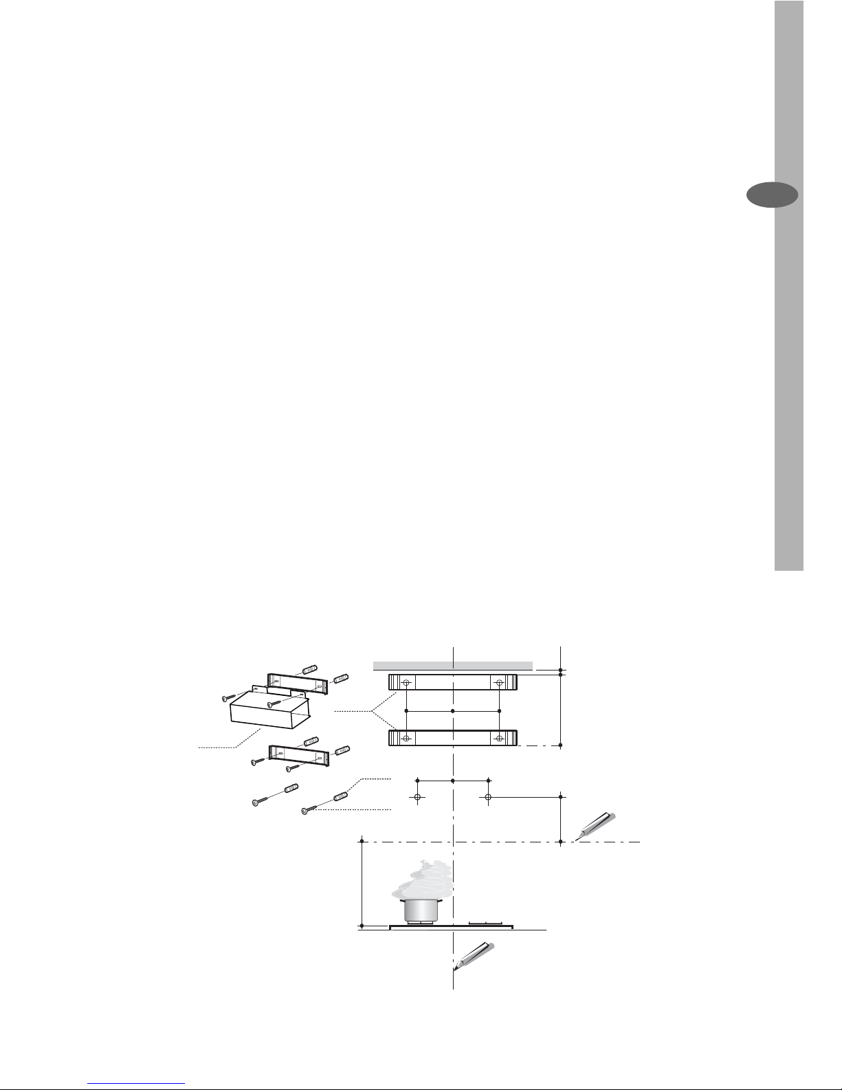
• Mark the wall at the centres of the
holes in the bracket.
• Mark a reference point as indicated
at 116 mm from the vertical reference
line and 306 mm above the horizontal
reference line.
• Repeat this operation on the other
side.
• Drill ø 8 mm holes at all the centre
points marked.
• Insert the wall plugs 11 in the holes.
• Fix the lower bracket 7.2.1 using the
12a screws (4,2 x 44,4) supplied.
• Fix the upper bracket 7.2.1 (and, in
case of hood installation in recycling
version, the air outlet connection 15)
using the 2 screws 12a (4,2 x 44,4)
supplied.
• Insert the two screws 12a (4,2 x 44,4)
supplied in the hood body fi xing holes,
leaving a gap of 5-6 mm between the
wall and the head of the screw.
Wall drilling and bracket fi xing
Wall marking:
• Draw a vertical line on the supporting
wall up to the ceiling, or as high as
practical, at the centre of the area in
which the hood will be installed.
• Draw a horizontal line at 650 mm
above the hob.
• Place bracket 7.2.1 on the wall as
shown about 1-2 mm from the ceiling
or upper limit aligning the centre with
the vertical reference line (distance
between the hole and the vertical line:
132,5 mm on both side of the line).
• Mark the wall at the centres of the
holes in the bracket.
• Place bracket 7.2.1 on the wall as
shown at X mm below the fi rst bracket
(X = height of the upper chimney section supplied), aligning the centre with
the vertical line (distance between the
hole and the vertical line:132,5 mm on
both side of the line).
11
12a
306
X
11 6
1÷2
11 6
650 min.
7.2.1
132,5 132,5
15
Page 10
10 electrolux Installation
EN
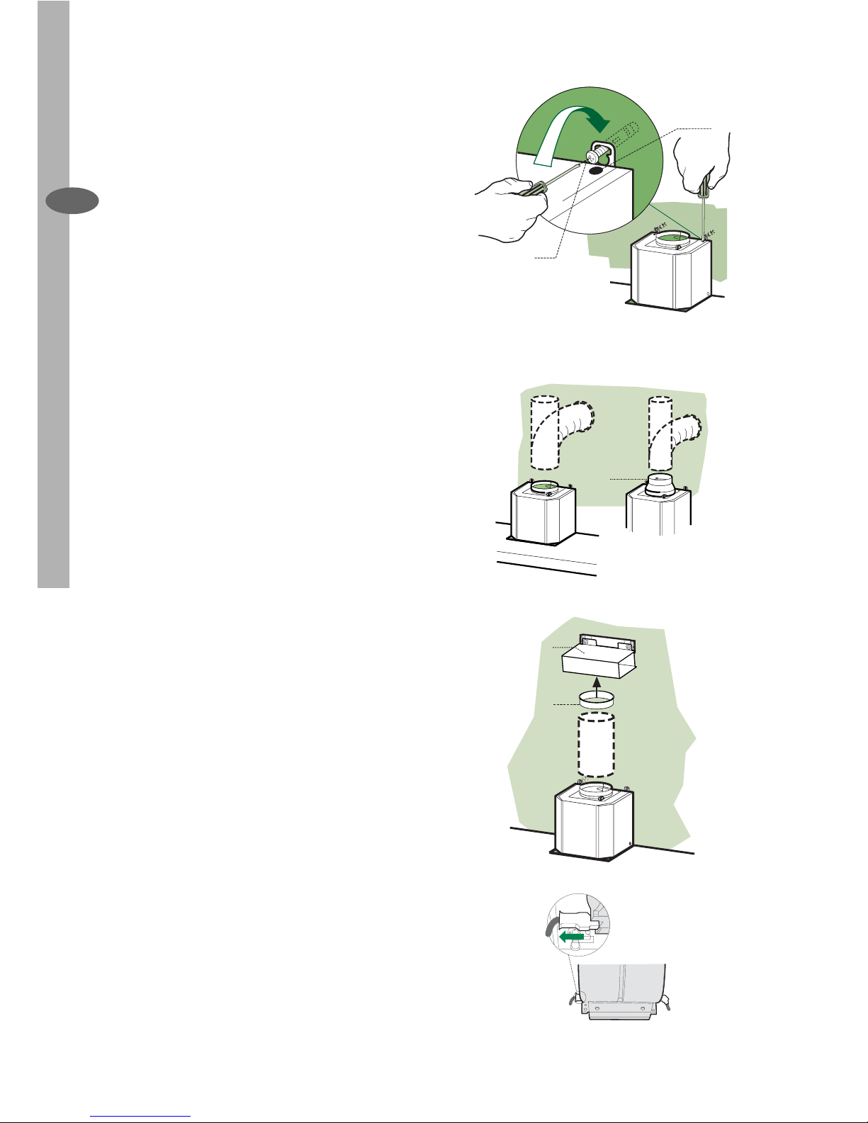
Hood body installation
• Before attaching the hood body,
tighten the two screws Vr located on
the hood body mounting points.
• Hook the hood body onto the screws
12a.
• Fully tighten support screws 12a.
• Adjust screws Vr to level the hood
body
Connection in Ducting Version
When installing the ducting version,
connect the hood to the chimney using
either a fl exible or rigid pipe ø 150 or
120 mm, the choice of which is left to
the installer.
• To install a ø 120 mm air exhaust connection, insert the reducer fl ange 9 on
the hood body outlet.
• Fix the pipe in position using suffi cient
pipe clamps (not supplied).
• Remove charcoal fi lters, if present.
Connection in Recycling Version
• Fix the fl ange 10 to the lower opening
of the connection 15.
• Connect the hood air outlet to the
fl ange in the lower part of the junction
using a rigid or fl exible ø 150 tube (by
installer’s choice).
• Ensure that the charcoal fi lters have
been fi tted.
Electrical Connection
• Connect the hood to the mains
through a two-pole switch having a
contact gap of at least 3 mm.
• Remove the grease fi lters (see para-
graph Maintenance) being sure that
the connector of the feeding cable is
correctly inserted in the socket placed
on the side of the fan.
12a
Vr
9
ø 120ø 150
ø 150
15
10
Page 11
Installation/Use electrolux 11
EN
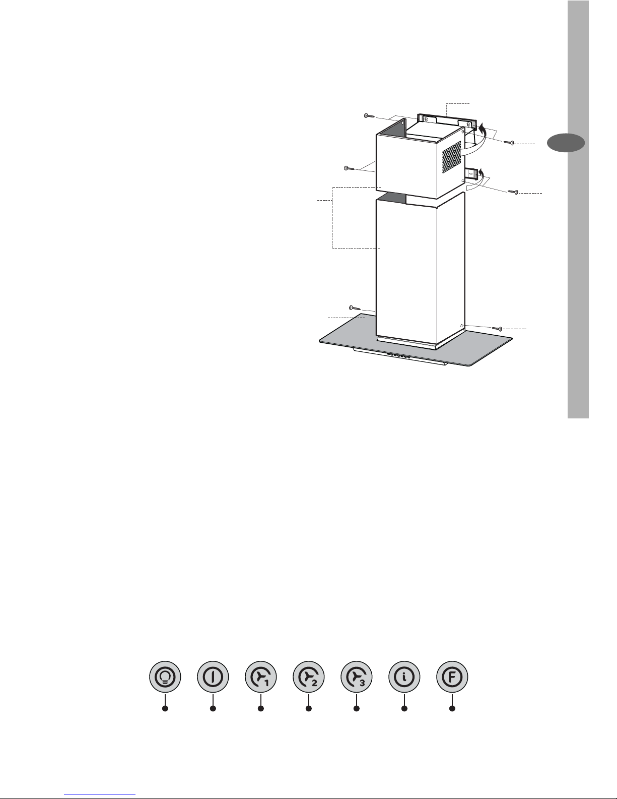
Chimney assembly
Upper Chimney
• Slightly widen the two sides of the upper Chimney and hook them behind
the brackets 7.2.1, making sure that
they are well seated.
• Secure the sides to the brackets using the 4 screws 12c (2,9 x 9,5) supplied.
• Make sure that the outlet of the extensions pieces is aligned with the chimney outlets.
Lower Chimney
• Slightly widen the two sides of the
Chimney and hook them between the
upper Chimney and the wall, making
sure that they are well seated.
• Fix the lower part laterally to the hood
body using the 2 screws 12c (2,9 x
9,5) supplied.
USE
The hood can be switched on pushing
directly onto the requested speed
without fi rstly having to select 0/1 but-
ton
L T1 T2 T3 T4 T5 F
1
7.2.1
2.1
2.2
2
12c
12c
12c
Page 12
12 electrolux Use
EN
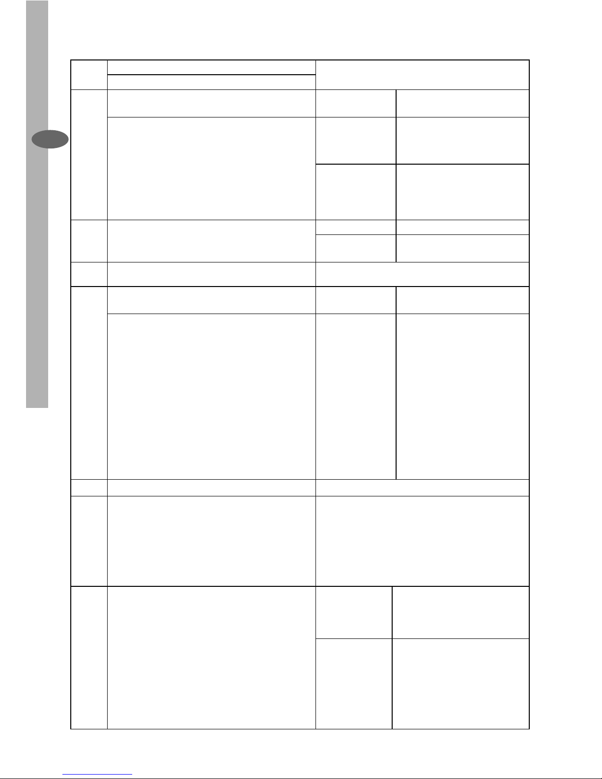
Touch
control
Basic functions Indicator lights
Dual Function
L
When briefl y pressed it switches the lighting
system on and off.
Touch control
unlit
Lights off
When pressed for 2 seconds it starts the
lighting system in “courtesy light” mode.
The lamps are fed at a reduced power of
approximately 5W. Such function can be
stopped by pressing the touch control for 2
seconds or just by pressing it shortly in order to
return to the normal lighting mode. In courtesy
light mode the touch control is not lit.
Touch control lit Lights on
Touch control
unlit
Courtesy light on
T1
When pressed the motor is stopped, regardless
of the speed it is set to.
Touch control lit Motor on
Touch control
unlit
Motor off
T2
When pressed the motor is set to the fi rst speed
Touch control lit
T3
By a brief pressing the motor is set to the second
speed.
Touch control lit Second speed on
By pressing the touch control for approximately
2 seconds the Delay function is enabled, i.e
delayed shutdown of the appliance ensuring
a complete elimination of the residual odours.
This function can be activated at OFF-position
and at 1°, 2° and 3°speeds. It can be stopped
in advance by pressing any of the touch
controls (T) with the exception of T3. The Delay
function works according to the following
scheme:
1°speed / OFF = 20 minuets
2°speed = 15 minutes
3°speed = 5 minutes
Flashing touch
control
Delay function on
T4
When pressed the motor is set to the third speed Touch control lit
T5
When pressed the motor is set to the intensive
speed timed to 5 minutes. At the end of 5
minutes of intensive speed the hood starts again
at the speed it was set to previously. In case the
hood is set to the intensive speed directly from
OFF-state it will then start from the fi rst speed
after 5 minutes of intensive speed.
Touch control lit
F
When pressed for 4 seconds it resets the fi lter
alarm signal indicated by fl ashing of the touch
control T1. This procedure can be carried out
only when the motor is stopped.
Touch control lit Metal grease fi lters saturation
alarm. Metal grease fi lters need
to be washed. The alarm starts
up after 100 working hours.
Flashing touch
control
Charcoal fi lter saturation
alarm. Charcoal fi lter has to
be replaced and metal grease
fi lters washed. The alarm
starts up after 200 working
hours. (Activation; check the
paragraph “Charcoal fi lter”)
Page 13
Maintenance electrolux 13
EN
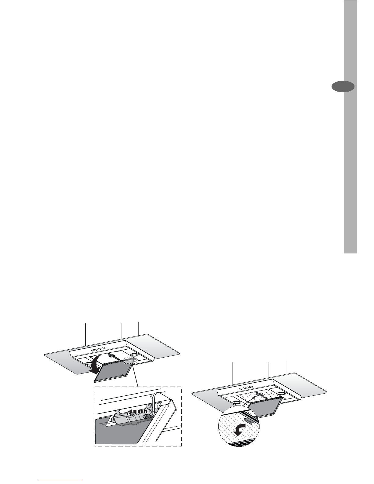
Cleaning the Comfort Panels
• Pull the Comfort Panel to open it.
• Disconnect the panel from the hood
canopy by sliding the fi xing pin lever.
• The comfort panel must never be
washed in a dishwasher.
• Clean the outside using a damp cloth
and neutral liquid detergent.
• Clean the inside as well using a damp
cloth and neutral detergent; do not
use wet cloths or sponges, or jets of
water; do not use abrasive substances.
• When the above operation has been
completed, hook the panel back to
the hood canopy and close it by turning the knob in the opposite direction.
MAINTENANCE
Cleaning of the Metal Cassette
Filters
Alarm reset
• Stop the motor.
• Press the F -touch control for at least
4 seconds until the T1 -touch control
fl ashes.
Cleaning the fi lters
• Filters can be washed in the dish machine. They need to be washed every
2 months or even more frequently in
case of particularly intensive use of
the hood.
• Pull the Comfort Panel to open it.
• Remove the fi lters one by one pushing
them lateraly and simultaneously pulling downwards.
• Any kind of bending of the fi lters has
to be avoided when washing them.
Before fi tting them again into the hood
make sure that they are completely
dry (The colour of the fi lter surface
may change throughout the time but
this has no infl uence to the fi lter ef-
fi ciency).
• When fi tting the fi lters into the hood
pay attention that they are placed in
correct position and that the handle
faces outwards.
• Close the comfort panel.
Page 14
14 electrolux Maintenance
EN
Replacing the Charcoal Filter
This fi lter cannot be washed or regene-
rated, and must be replaced when the F
touch control starts to fl ash, or at least
once every 4 months. The alarm is only
triggered when the motor is on.
Enabling/Disabling the alarm signal
• In Recirculation Version Hoods, the
Filter saturation Alarm must be enabled at the time of installation or later.
• Switch off the lights and the motor.
• Disconnect the mains power supply
to the hood by removing the motor
unit power supply cable connector,
switching off the power supply at the
Mains or turning the Main switch off.
• Restore the connection, pressing and
holding T2.
• Release the touch control, touch
controls L, T2 and F will light up normally.
• Within 3 seconds press the touch
control F until the key itself fl ashes to
confi rm as follows:
• 2 fl ashes – Charcoal Filter saturation
Alarm ENABLED
• 1 fl ash - Charcoal Filter saturation
Alarm DISABLED
Reset the alarm signal
• Stop the motor.
• Press the touch control F for at least
4 seconds, until the touch control T1
fl ashes.
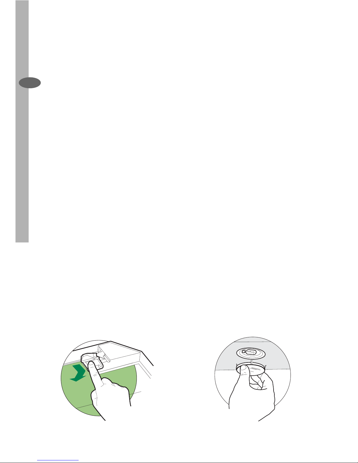
Replace the Filter
• Pull the Comfort Panel to open it.
• Remove the metal grease fi lters.
• Remove the saturated charcoal fi lter,
turning the fasteners provided.
• Fit the new fi lter and fasten it its cor-
rect position.
• Put the metal grease fi lters in their
seats.
• Close the comfort panel.
Light replacement
20 W halogen light.
• Remove the snap-on lamp cover by
levering it from under the metal ring,
supporting it with one hand.
• Remove the halogen lamp from the
lamp holder by pulling gently.
• Replace the lamp with a new one of
the same type, making sure that you
insert the two pins properly into the
housings on the lamp holder.
• Replace the snap-on lamp cover.
Page 15

Page 16

Page 17

Page 18
Page 19
www.electrolux.com
436003554_01 - 061204
 Loading...