

Page 1

USER MANUAL
EFC70011
Page 2

We were thinking of you
when we made this product
Page 3
EN
IMPORTANT SAFETY INFORMATION 4
YOUR APPLIANCE 5
OPERATING INSTRUCTIONS 6
MAINTENANCE AND CLEANING 8
SOMETHING NOT WORKING 11
GUARANTEE/CUSTOMER SERVICE 12
GUARANTEE CONDITIONS 13
INSTALLATION INSTRUCTIONS 15
ELECTRICAL CONNECTIONS 16
INSTALLING THE COOKER HOOD 17
EN
Welcome to the world of Electrolux
Thank you for choosing a fi rst class
product from Electrolux, which
hopefully will provide you with lots of
pleasure in the future. The Electrolux
ambition is to offer a wide variety of
quality products that make your life
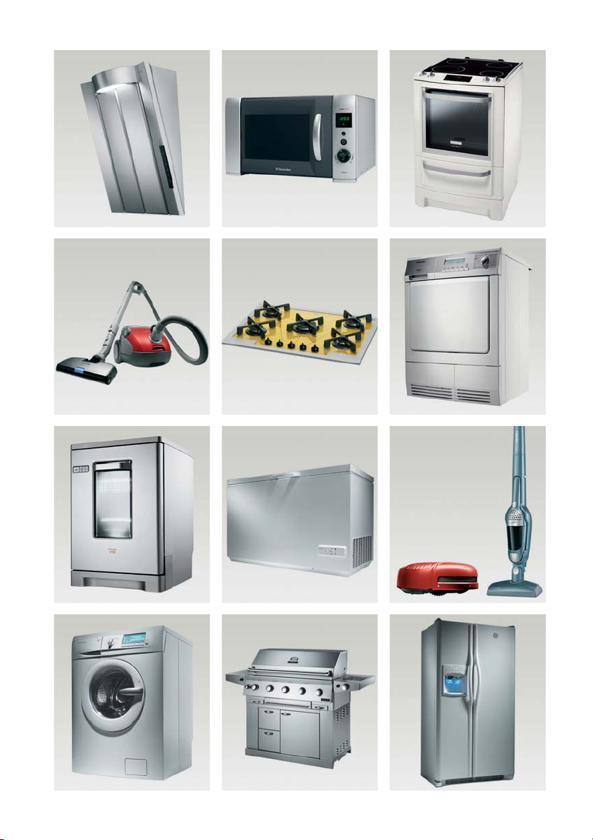
more comfortable. You fi nd some
examples on the cover in this manual.
Please take a few minutes to study this
manual so that you can take advantage
of the benefi ts of your new machine.
We promise that it will provide a
superior User Experience delivering
Ease-of-Mind.
Good luck!
electrolux 3
Guide to use the instruction book
The following Symbols will be found in the text to guide you through the instruction book
Safety instructions Step by step instructions
Page 4

4 electrolux IMPORTANT SAFETY INFORMATION
IMPORTANT SAFETY INFORMATION
These warnings are provided in the interests of your safety. Ensure that you
understand them all before installing or using this appliance. Your safety is of
paramount importance. If you are unsure about any of the meanings of these
EN
warnings contact the Customer Care Department.
Installation
• Any installation work must be undertaken
by a qualifi ed electrician or a competent
person.
• This hood must be installed in accordance
with the installation instructions and all
measurements must be adhered to.
• If the cooker hood is installed for use
above a gas appliance then the provision
for ventilation must be in accordance
with the Gas Safety Codes of Practice
BS.6172, BS.5440 and BS.6891 (Natural
Gas) and BS.5482 (LP Gas) 1994, the
Gas Safety (Installation & Use) Regulations,
the Building Regulations issued by
the Department of the Environment,
the Building standards (Scotland)
(Consolidated) Regulations issued by the
Scottish Development Department.
• The fan motor of this cooker hood
incorporates a cut-out device which will
operate if the cooker hood is installed
below the minimum height recommended
under section ‘Clearance Height’, or if the
motor becomes overheated. If the cutout device is activated, switch off the fan
motor and allow the cooker hood to cool.
The cut-out device will reset itself when
the fan motor has cooled signifi cantly.
• It is dangerous to alter the specifi cations
or modify this product in any way.
• When installed between adjoining wall
cabinets the wall cabinets must not
overhang the hob.
• If the room where the hood is to be used
contains a fuel burning appliance such as
a central heating boiler then its fl ue must
be of the room sealed or balanced fl ue
type.
• If other types of fl ue or appliances are
fi tted ensure that there is an adequate
supply of air to the room.
• The ducting system for this appliance
• Do not install above a cooker with a high
Child Safety
• This appliance is designed to be operated
During Use
• This product is for domestic use only.
• Never leave frying pans unattended during
• Never do flambé cooking under this
• Do not leave naked fl ames under the
• This cooker hood is designed to extract
Maintenance and Service
• This appliance can be a hazard if the
• Under no circumstances should you
must not be connected to any existing
ventilation system which is being used
for any other purpose.
level grill.
by adults. Children should not be allowed
to tamper with the controls or play with
the appliance.
use as over-heated fats and oils might
catch fi re.
cooker hood.
hood.
unpleasant odours from the kitchen, it will
not extract steam.
synthetic paper and charcoal fi lters are
not replaced as recommended.
attempt to repair the appliance yourself.
Repairs carried out by inexperienced
persons may cause injury or more
serious malfunction. Refer to your local
Electrolux Service Force Centre. Always
insist on genuine spare parts.
Page 5
YOUR APPLIANCE AND OPERATING INSTRUCTIONS electrolux 5
YOUR APPLIANCE
EN
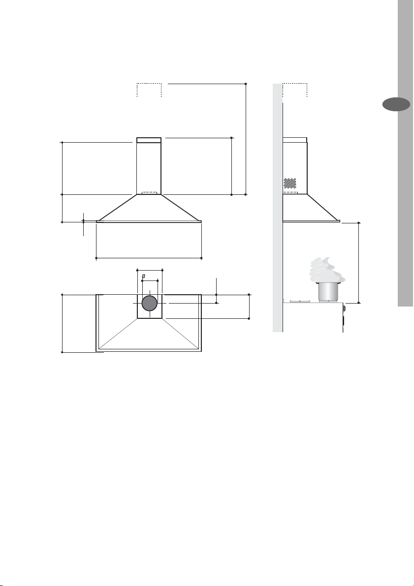
max. 670
360
240
18
598 - 698 - 898
210
150
490
min. 490
650 min.
100
205
Page 6
6 electrolux YOUR APPLIANCE AND OPERATING INSTRUCTIONS
OPERATING INSTRUCTIONS
The cooker hood is designed to extract
unpleasant odours from the kitchen, it
will not extract steam. The appliance
can be installed to recirculate or extract
EN
contaminated air.
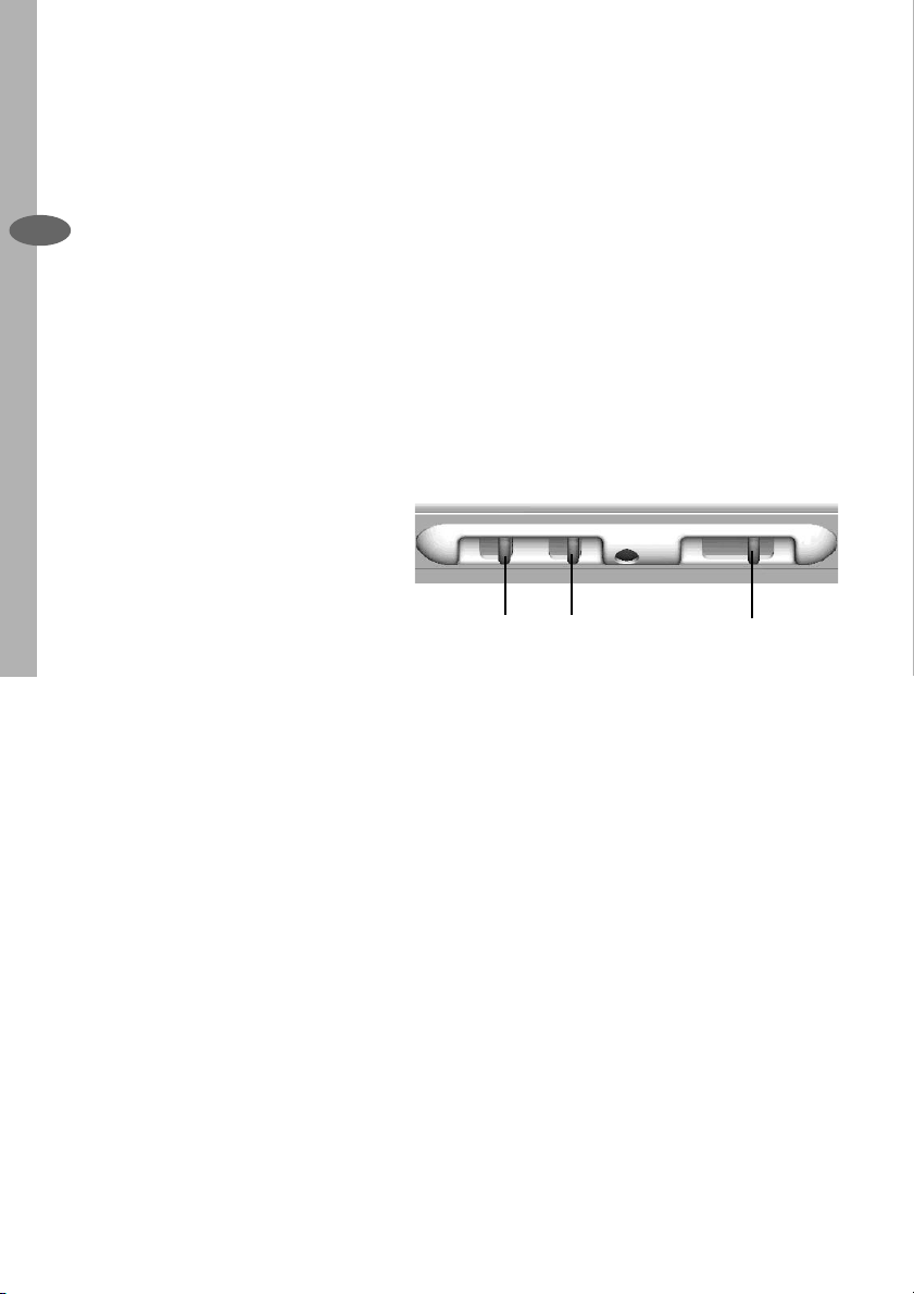
Cooker Hood Controls
The cooker hood functions are
controlled by three switches located on
the underside of the hood immediately
in front of the metal grease fi lters.
L. Light ON/OFF control
0 - Off
1 - On
M.Motor ON/OFF control
0 - Off
1 - On
0 1 0 1
L
V. Fan Speed Control
Position 1 - Low
Position 2 - Normal
Position 3 - Boost
1 2 3
MV
Page 7
To Operate
Select the required fan speed and light
if required.
electrolux 7
Recirculation
In the recirculation mode the
contaminated air enters the cooker
hood through the grease fi lters. The
air is cleaned by passing through the
charcoal fi lters before being passed
back into the kitchen through the grilles
in either side of the chimney stack.
Extraction
In the extraction mode the contaminated
air enters the cooker hood passing
through the grease fi lters and is passed
out through the ducting into the
atmosphere.
To obtain the best performance when
cooking it is advisable to switch the
cooker hood on for a few minutes before
you start cooking and leave it running
for about 15 minutes after fi nishing.
When used in the ducting mode the
charcoal fi lters are not required.
Never do fl ambé cooking under this
cooker hood.
Never leave frying pans unattended
during use, as over-heated fats and
oils can catch fi re.
EN
Do not leave naked fl ames under the
cooker hood.
Ensure heating areas on your hob
are covered with pots and pans
when using the hob and cooker hood
simultaneously.
Page 8
8 electrolux MAINTENANCE AND CLEANING
MAINTENANCE AND CLEANING
Before carrying out any maintenance
or cleaning isolate the cooker hood
EN
from the mains supply.
The cooker hood must be kept clean,
as a build up of grease or fat can be
a fi re hazard.
External Cleaning
Wipe the cooker hood frequently
with warm soapy water using a mild
detergent.
Never use scouring pads or abrasive
cleaners.
Never use excessive amounts of water
when cleaning particularly around the
control panel.
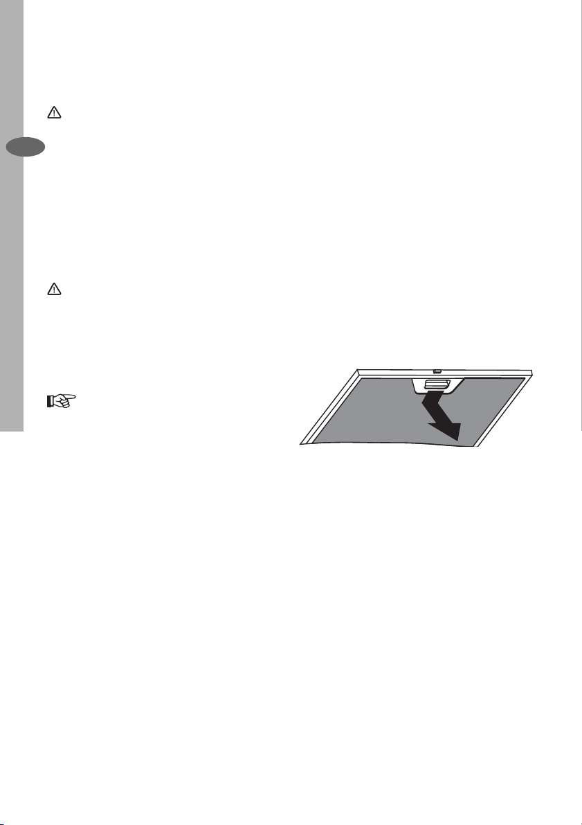
Remove the metal grease
fi lters one at a time by:
Releasing the catches on
the fi lters, the fi lters can be
removed.
The metal grease fi lters should be
washed, by hand, in mild soapy water or
in a dishwasher. Allow to dry completely
before replacing.
Page 9

Before carrying out any maintenance
or cleaning isolate the cooker hood
from the mains supply.
MAINTENANCE AND CLEANING electrolux 9
Charcoal Filters
In the recirculation mode the charcoal
fi lters absorb smells and unwanted
odours.
The charcoal fi lters cannot be cleaned,
we recommend they should be replaced
approximately every three months or
more often if the hood is used for more
than three hours per day.
To Remove/Replace the
Charcoal Filters
1. First remove the metal grease fi lters.
2. Rotate the charcoal fi lter anti-
clockwise (A) and remove.
3. To replace the charcoal fi lters, remove
the metal grease fi lters.
4. Place the fi lter over the inlet grille at
either end of the fan housing and
rotate clockwise (B) into position.
This appliance can be a possible fi re
hazard if the grease and charcoal fi l-
ters are not cleaned and replaced as
recommended.
B
EN
A
Changing the Light Bulb
1. Remove the screw fastening the lamp
cover.
2. Rotate the light bulb anti-clockwise to
unscrew.
3. To replace the light bulb insert a
replacement into the holder then
rotate the bulb clockwise into
position. Ensure you take care not to
overtighten the bulb.
4. Replace the lamp cover.
Page 10

10 electrolux MAINTENANCE AND CLEANING
If the light bulb fails to function check
that the bulb is fully screwed into the
holder. If bulb failure has occurred then
it should be replaced with a 220-240
Volt 40W clear globe shaped bulb with
EN
a small E14 screw thread.
Replacement fi lters and light bulbs
can be obtained from your local
Service Force Centre.
Page 11
SOMETHING NOT WORKING electrolux 11
SOMETHING NOT WORKING
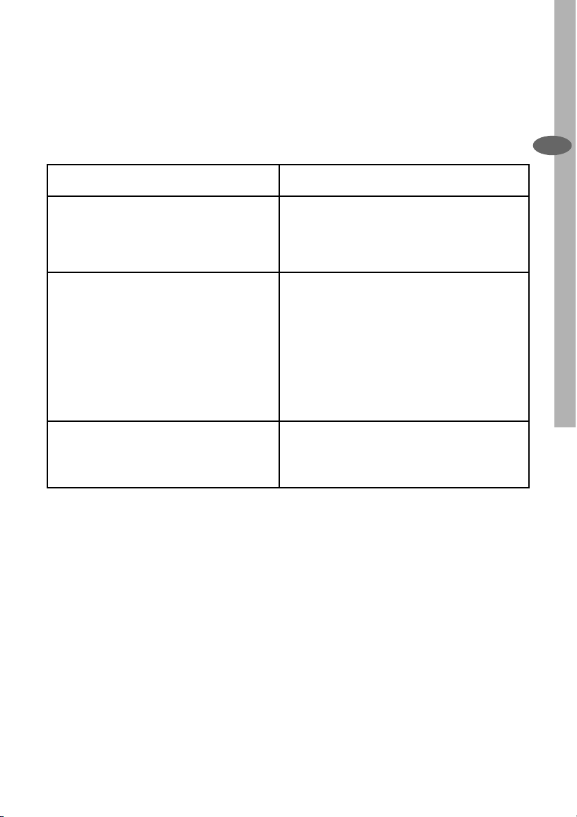
If, having followed these instructions carefully, your cooker hood fails to work properly
please carry out the following checks.
EN
Symptom
The cooker hood will not start
The cooker hood is not working
effectively
The cooker hood has switched off
during operation
If after all these checks, the fault persists,
contact your local Service Force Centre,
quoting the model and serial number.
Please note that it will be necessary to provide proof of purchase for any in-guarantee
service calls.
Solution
• Check the hood is connected to the
electricity supply.
• Make sure the switch is in the ‘ON’ posi
tion.
• The fan speed is set high enough for the
task
• The grease fi lter is clean.
• The kitchen is adequately vented to allow
the entry of fresh air.
• If set up for recirculation, check that the
charcoal fi lter is still effective.
• If set up for extraction, check that the
ducting and outlets are not blocked.
• The safety cut-out device has been trip
ped.
• Tum off the hob and then wait for the
device to reset.
In-guarantee customers should ensure
that the above checks have been made
as the engineer will make a charge if
the fault is not a mechanical or electrical breakdown.
Page 12

12 electrolux GUARANTEE/CUSTOMER SERVICE
GUARANTEE/CUSTOMER SERVICE
Standard guarantee conditions
We, Electrolux, undertake that if within
12 months of the date of the purchase
EN
this Electrolux appliance or any part
thereof is proved to be defective by
reason only of faulty workmanship or
materials, we will, at our option repair
or replace the same FREE OF CHARGE
for labour, materials or carriage on
condition that:
• The appliance has been correctly
installed and used only on the
electricity supply stated on the rating
plate.
• The appliance has been used for
normal domestic purposes only, and
in accordance with the manufacturer’s
instructions.
• The appliance has not been serviced,
maintained, repaired, taken apart or
tampered with by any person not
authorised by us.
• Electrolux Service Force Centre must
undertake all service work under this
guarantee
• Any appliance or defective part
replaced shall become the Company’s
property.
• This guarantee is in addition to your
statutory and other legal rights.
Exclusions
• Damage or calls resulting from
transportation, improper use or
neglect, the replacement of any light
bulbs or removable parts of glass or
plastic.
• Costs incurred for calls to put right
an appliance which is improperly
installed or calls to appliances outside
the United Kingdom.
• Appliances found to be in use within
a commercial environment, plus
those which are subject to rental
agreements.
• Products of Electrolux manufacturer
that are not marketed by Electrolux
Service and Spare Parts
In the event of your appliance requiring
service, or if you wish to purchase spare
parts, please contact your local Service
Force Centre by telephoning
0870 5 929 929
Your telephone call will be automatically
routed to the Service Force Centre
covering your postcode area.
For the address of your local Service
Force Centre and further information
about Service Force, please visit the
website at
www.serviceforce.co.uk
Before calling out an engineer, please
ensure you have read the details under
the heading “Something not working”
When you contact the Service Force
Centre you will need to give the
following details:
1.Your name, address and postcode.
2.Your telephone number.
3.Clear concise details of the fault.
4.The model and Serial number of the
appliance (found on the rating plate).
5.The purchase date.
Please note a valid purchase receipt or
guarantee documentation is required for
in guarantee service calls.
Page 13

GUARANTEE CONDITIONS
Customer Care
For general enquiries concerning your
Electrolux appliance, or for further
information on Electrolux products
please contact our Customer Care
Department by letter or telephone at
the address below or visit our website
at www.electrolux.co.uk
Customer Care Department
Electrolux Major Appliances
Addington Way
Luton
Bedfordshire, LU4 9QQ
Tel: 08705 950 950 (*)
(*) Calls may be recorded for training
purposes
GUARANTEE CONDITIONS electrolux 13
European Guarantee
This appliance is guaranteed by
Electrolux in each of the countries
listed at the back of this user manual,
for the period specifi ed in the appliance
guarantee or otherwise by law. If you
move from one of these countries to
another of the countries listed below the
appliance guarantee will move with you
subject to the following qualifi cations:-
• The appliance guarantee starts from
the date you fi rst purchased the
appliance which will be evidenced
by production of a valid purchase
document issued by the seller of the
appliance.
• The appliance guarantee is for the
same period and to the same extent
for labour and parts as exists in
your new country of residence for
this particular model or range of
appliances.
• The appliance guarantee is personal
to the original purchaser of the
appliance and cannot be transferred
to another user.
• The appliance is installed and used
in accordance with instructions
issued by Electrolux and is only used
within the home, i.e. is not used for
commercial purposes.
• The appliance is installed in
accordance with all relevant
regulations in force within your new
country of residence.
EN
The provisions of this European Guarantee
do not affect any of the rights granted to you
by law.
Page 14
14 electrolux
www.electrolux.com
à
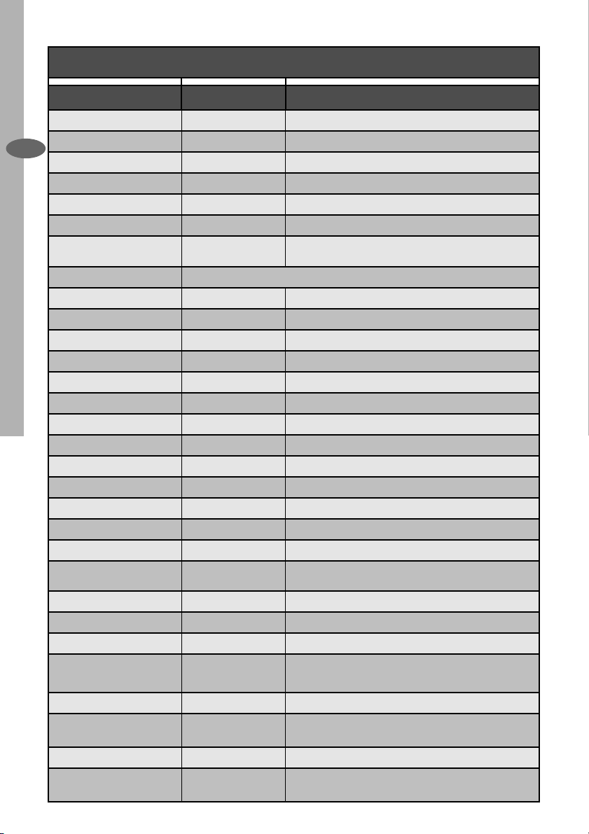
Albania +35 5 4 261 450 Rr. Pjeter Bogdani Nr. 7 Tirane
Belgique/België/Belgien +32 2 363 04 44 Bergensesteenweg 719, 1502 Lembeek
EN
Česká republika +420 2 61 12 61 12 Budějovická 3, Praha 4, 140 21
Danmark +45 70 11 74 00 Sjællandsgade 2, 7000 Fredericia
Deutschland +49 180 32 26 622 Muggenhofer Str. 135, 90429 Nürnberg
Eesti +37 2 66 50 030 Mustamäe tee 24, 10621 Tallinn
España +34 902 11 63 88 Carretera M-300, Km. 29,900 Alcalá de Henares Madrid
France www.electrolux.fr
Great Britain +44 8705 929 929 Addington Way, Luton, Bedfordshire LU4 9QQ
Hellas +30 23 10 56 19 70 4, Limnou Str., 54627 Thessaloniki
Hrvatska +385 1 63 23 338 Slavonska avenija 3, 10000 Zagreb
Ireland +353 1 40 90 753 Long Mile Road Dublin 12
Italia +39 (0) 434 558500 C.so Lino Zanussi, 26 - 33080 Porcia (PN)
Latvija +37 17 84 59 34 Kr. Barona iela 130/2, LV-1012, Riga
Lietuva +370 5 2780609 Verkių 29, LT-09108 Vilnius
Luxembourg +35 2 42 43 13 01 Rue de Bitbourg, 7, L-1273 Hamm
Magyarország +36 1 252 1773 H-1142 Budapest XIV, Erzsébet királyné útja 87
Nederland +31 17 24 68 300 Vennootsweg 1, 2404 CG - Alphen aan den Rijn
Norge +47 81 5 30 222 Risløkkvn. 2 , 0508 Oslo
Österreich +43 18 66 400 Herziggasse 9, 1230 Wien
Polska +48 22 43 47 300 ul. Kolejowa 5/7, Warsaw
Portugal +35 12 14 40 39 39
Romania +40 21 451 20 30 Str. Garii Progresului 2, S4, 040671 RO
Schweiz - Suisse - Svizzera +41 62 88 99 111 Industriestrasse 10, CH-5506 Mägenwil
Slovenija +38 61 24 25 731 Tržaška 132, 1000 Ljubljana
Slovensko +421 2 43 33 43 22
Suomi +35 8 26 22 33 00 Konepajanranta 4, 28100 Pori
Sverige +46 (0)771 76 76 76
Türkiye +90 21 22 93 10 25 Tarlabașı caddesi no : 35 Taksim İstanbul
Россия +7 095 937 7837
Quinta da Fonte - Edifi cio Gonçalves Zarco - Q 35 -2774-
518 Paço de Arcos
Electrolux Slovakia s.r.o., Electrolux Domáce spotrebiče SK,
Seberíniho 1, 821 03 Bratislava
Electrolux Service, S:t Göransgatan 143, S-105 45
Stockholm
129090 Москва, Олимпийский проспект, 16, БЦ
“Олимпик”
Page 15
INSTALLATION INSTRUCTIONS electrolux 15
INSTALLATION INSTRUCTIONS
It is dangerous to alter the specifi cations or attempt to modify this product in any way.
Technical Information
DIMENSIONS HEIGHT OF CANOPY: 24cm
HEIGHT OF CHIMNEY: (UPPER SECTION) 32cm
(LOWER SECTION) 36cm
WIDTH OF CANOPY : 69,8cm
DEPTH OF CANOPY: 49cm
GROSS : 16,5kg
NET : 12,8kg
ELECTRICAL SUPPLY: VOLTAGE: 220-240 V 50Hz
POWER CONSUMPTION: 230W
FAN MOTOR: 150W
LIGHT BULB: (2 x 40 W) 80W
SUITABLE FOR INSTALLATION
ABOVE: ELECTRIC HOB: 7KW (max)
GAS HOB: 10KW (max)
SLOT-IN GAS COOKER 13.5KW (max)
SLOT-IN ELECTRIC COOKER 12.4KW (max)
Note: CE Marking certifi es that this appliance complies with the requirements
laid down in EEC directive 89:336. (Electromagnetic compatibility) and subsequent modifi cations and Low Voltage directive 72/23/E.
EN
The symbol
shall be handed over to the applicable collection point for the recycling of electrical and electronic equipment. By ensuring this product
is disposed of correctly, you will help prevent potential negative consequences for the environment and human health, which could
otherwise be caused by inappropriate waste handling of this product. For more detailed information about recycling of this product,
please contact your local city offi ce, your household waste disposal service or the shop where you purchased the product.
on the product or on its packaging indicates that this product may not be treated as household waste. Instead it
Page 16

16 electrolux ELECTRICAL CONNECTIONS
ELECTRICAL CONNECTIONS
DOUBLE INSULATED DO NOT EARTH
Electrical Requirements
EN
Any permanent electrical installation
must comply with the latest I.E.E.
Regulations and local Electricity Board
regulations. For your own safety this
should be undertaken by a qualifi ed
electrician e.g. your local Electricity
Board, or a contractor who is on the
roll of the National Inspection Council
for Electrical Installation Contracting
(NICEIC).
Electrical Connection
Before connecting to the mains
supply ensure that the mains voltage
corresponds to the voltage on the rating
plate inside the cooker hood.
This appliance is fi tted with a 2 core
mains cable and must be permanently
connected to the electricity supply
via a double-pole switch having
3mm minimum contact gap on each
pole. A Switched Fuse Connection
Unit to BS1363 Part 4, fi tted with
a 3 Amp fuse, is a recommended
mains supply connection accessory
to ensure compliance with the Safety
Requirements applicable to fi xed wiring
instructions.
This appliance conforms to BS 800:
1988 and EEC Directive No. 78 308
regarding suppression of ra dio and
television interference.
Page 17
INSTALLING THE COOKER HOOD electrolux 17
INSTALLING THE COOKER HOOD
Please ensure that when the appliance
is installed it is easily accessible to an
engineer in the event of a breakdown.
All installations must comply with the
local authorities requirements for the
discharge of exhaust air.
Incorrect installation may affect the
safety of this cooker hood.
Installation Requirements
Before installation check the wall to
which the cooker hood is to be fi tted
for electric cables, water pipes or
gas.
This cooker hood is designed to be
fi xed to any vertical surface over a
cooking area, and can be used in the
extraction (ducted to the outside) or
recirculation mode.
The installation work must be undertaken
by a qualifi ed and competent person.
The manufacturer disclaims any
responsibility for damage due to
incorrect installation of the cooker
hood or if the hood is not installed in
compliance with relevant regulations
controlling this type of installation.
EN
Unpacking
Before unpacking the cooker hood
position the carton with the arrows
pointing upwards as illustrated on the
carton.
Page 18
18 electrolux INSTALLING THE COOKER HOOD
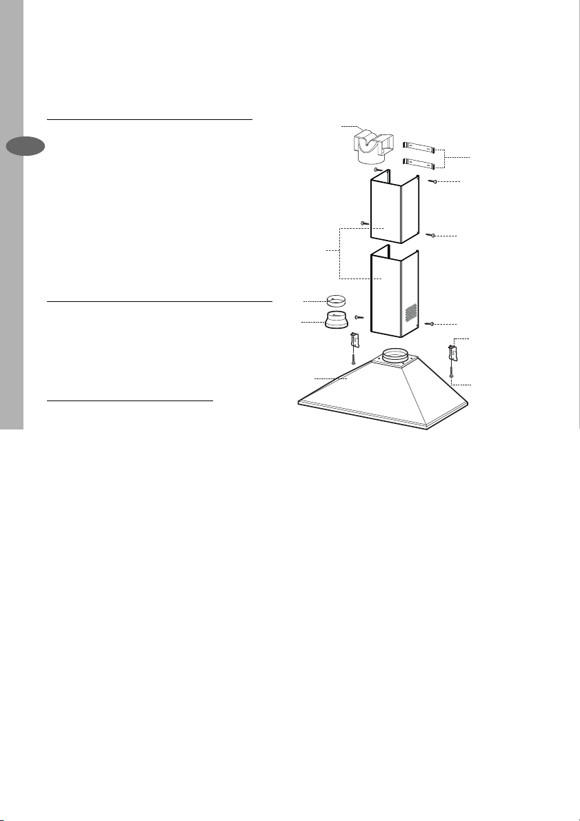
The cooker hood is made up of the
following components:
Ref Qty Product Components
1 1 Hood body, complete with
EN
controls, lighting, fan and
fi lters.
2 1 Telescopic Chimney
comprising:
2.1 1 Upper section
2.2 1 Lower section
9 1 ø150-120 Ducting spigot
10 1 ø120-125 Ducting fl ange
15 1 Air outlet connector
Qty Installation Components
Ref
7.1 2 Hood body fi xing brackets
7.2.1 2 Upper chimney wall fi xing
brackets
12c 6 Chimney fi xing screws
12d 2 Screws M4x25
Ref Qty Documentation
1 Instruction booklet
15
7.2.1
12c
2.1
2
2.2
10
9
1
12c
12c
7.1
12d
Page 19
INSTALLING THE COOKER HOOD electrolux 19
Clearance Height
The cooker hood is designed to be
fi tted over a cooking appliance at the
clearance heights stated, providing
the maximum output of the appliance
beneath does not exceed the maximums
quoted in the Technical Specifi cations.
If the output of the appliance below the
cooker hood exceeds the maximum
outputs quoted, please refer to the
cooker manufacturer’s installation
instructions.
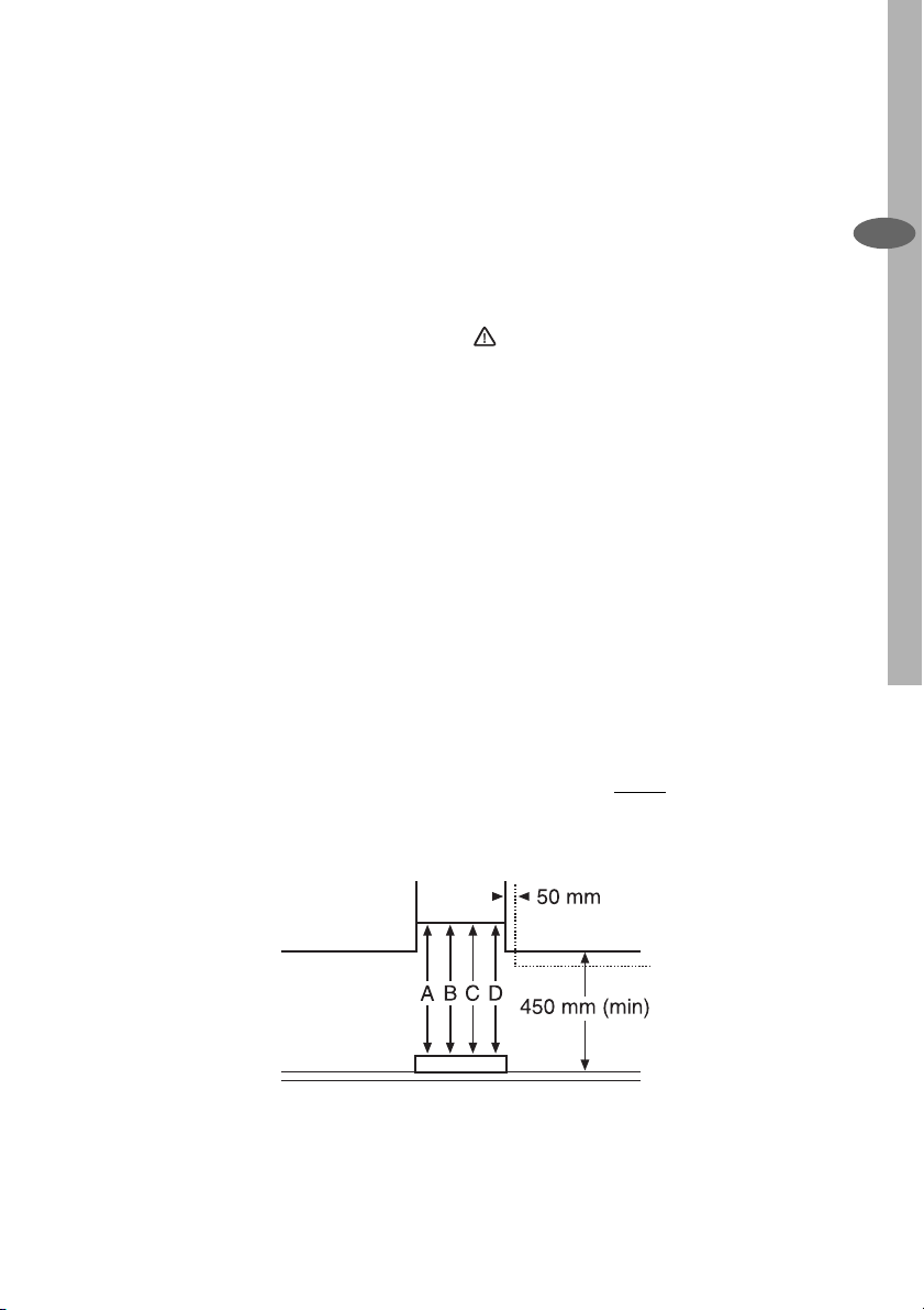
A clearance height of 650mm (25 1/2 ”)
is required when installed above a builtin electric hob, or 700mm (27 1/2 ”)
when installed above a built-in gas hob.
A clearance height of 685mm (27”) is
required when installed above a slot-in
electric cooker, or 787mm
(30 1/2 ”) when installed above a slot-in
gas cooker.
When installed between adjoining wall
cabinets, the wall cabinets must not
overhang the hob and the distance
between the underside of the cabinet
and the worktop must be 450mm. If
the height of the wall cabinet is less
than 450mm, a gap of 50mm must be
maintained either side of the hob.
This cooker hood must not be instal-
led above a cooking appliance with a
high level grill.
The hood can be installed above these
heights but for optimum performance
it should be installed at the distances
quoted for the appropriate heat
source.
This appliance can be used in
either extraction mode (ducting) or
recycling mode (fi ltering).
The hood is supplied suitable for
recirculation with the charcoal fi lters
fi tted.
When used in the extraction mode
(ducting) the charcoal fi lters are not
required and must be removed and
destroyed.
EN
Hob
A: Built-in Electric Hob: 650mm clearance
B: Built-in Gas hob: 700mm clearance
C: Slot-in Electric Cooker: 685mm clearance
D: Slot-in Gas Cooker: 787mm clearance
Page 20
20 electrolux INSTALLING THE COOKER HOOD
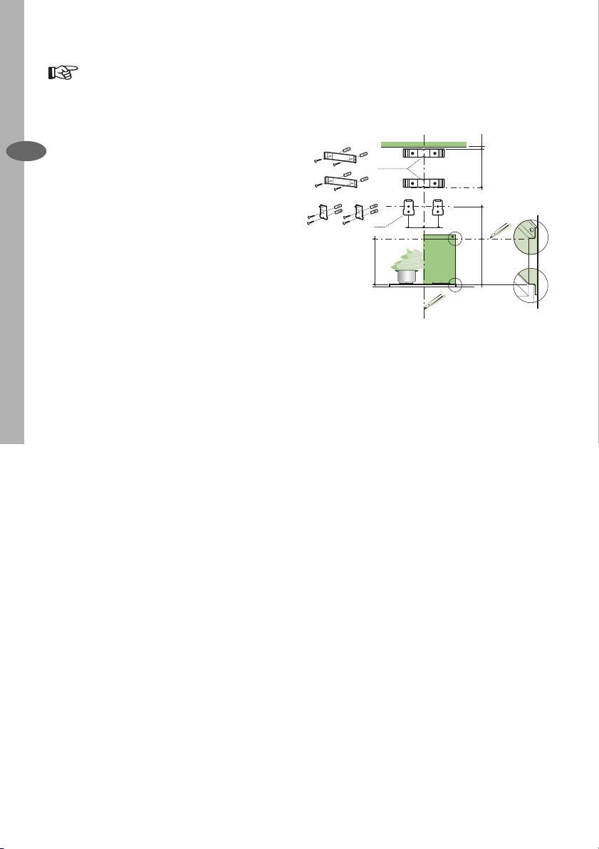
Fitting the Wall Brackets
• Draw a vertical line on the supporting
wall up to the ceiling, or as high as
practical, at the centre of the area in
EN
which the hood will be installed.
• Draw a horizontal line at 650 mm
above the hob for installation without
the back panel, or at height H
(H=height of the visible part of the
panel) for installation with the back
panel.
• Place bracket 7.2.1 on the wall as
shown about 1-2 mm from the ceiling
or upper limit aligning the centre
(notch) with the vertical reference line.
• Mark the wall at the centres of the
holes in the bracket.
• Place bracket 7.2.1 on the wall as
shown at X mm below the fi rst bracket
(X = height of the upper chimney
section supplied), aligning the centre
(notch) with the vertical line.
• Mark the wall at the centres of the
holes in the bracket.
• Place bracket 7.1 as shown 95
mm from the vertical reference line
and 210 mm above the horizontal
reference line.
• Mark the centres of the holes in the
bracket.
• Repeat this operation on the other
side.
7.2.1
7.1
650 min.
1÷2
X
95
95
210
H
Page 21
INSTALLING THE COOKER HOOD electrolux 21
Splashback (OPTIONAL)
The Splashback must be fi tted before
fi xing the hood body and, if it is to be
fi xed at both top and bottom, must
be fi tted at the correct height prior to
installing the bases. As this operation
is rather complex, it should be carried
out either by the kitchen installer or a
qualifi ed person who knows the fi nal
dimensions of the units.
For fi xing at the top only, proceed as
follows:
• Rest the back panel on the base,
inserting the lower plate between the
upper surface and the wall, centring it
on the vertical reference line.
• Mark the centres of the two holes in
the upper plate.
• Drill ø 8 mm holes at all the centre
points marked.
• Insert the wall plugs (not supplied) in
the holes.
• Fix the brackets using the screws (not
supplied).
• Fix the back panel (where present)
using the screws (not supplied).
Note: If the hood is to be installed onto
a hollow construction or plaster or
partition board wall then special fi xing
screws will be required (not supplied).
EN
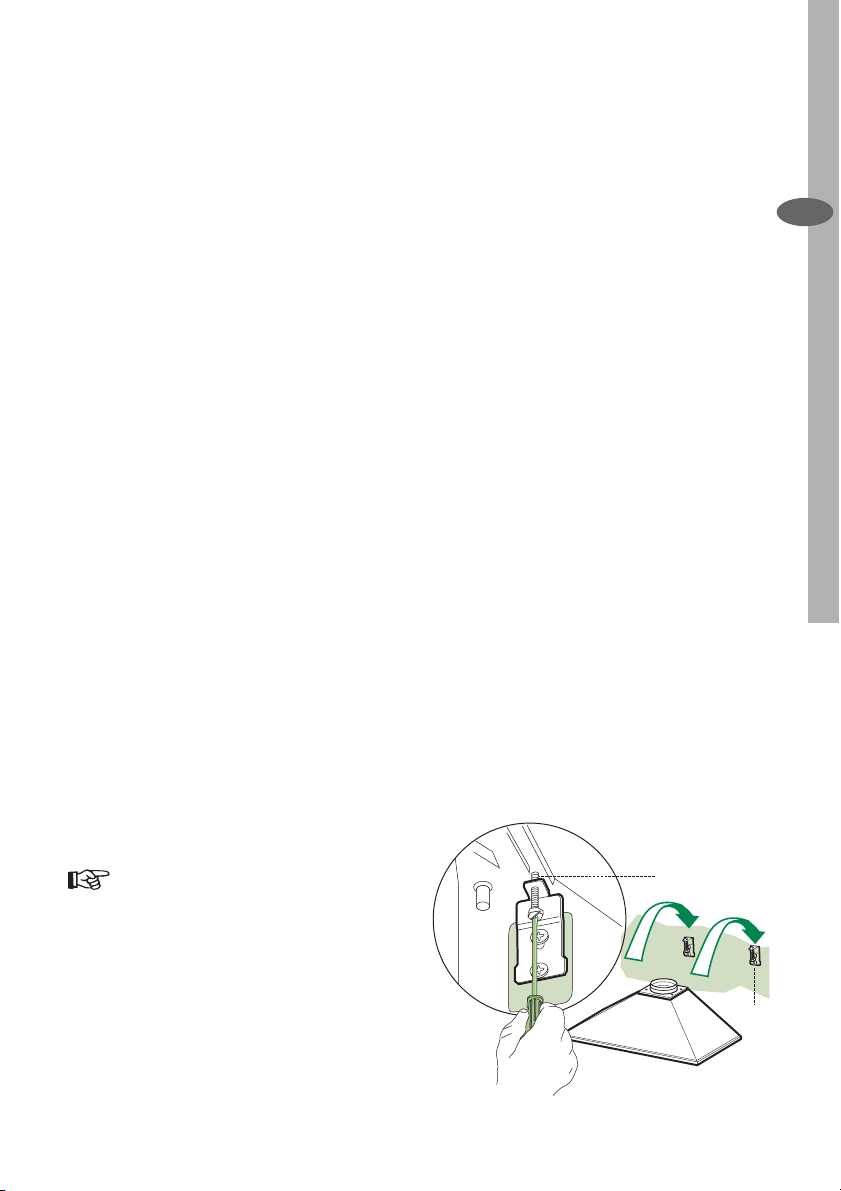
Fitting the Canopy Hood
• Screw the two screws item 12d
supplied onto the brackets 7.1.
• Hook the hood body onto the bracket
7.1, centring it around the vertical
line.
• Use the adjusting screws item 12d
underneath the hood to level the hood
body
12.d
7.1
Page 22
22 electrolux INSTALLING THE COOKER HOOD
Extraction (Ducted)
The cooker hood is more effective when
installed in the extraction mode (ducted
to the outside).
Venting kits may be purchased through
EN
your retailer or DIY store, and must be
evacuated through an outside vent of
ø125 (5ins) or ø150mm (6ins).
The ducting used must be manufactured
from fi re retardent material conforming
to the relevant British Standard or DIN
4102-B1.
When the cooker hood is ducted to
the outside the charcoal fi lter must be
removed.
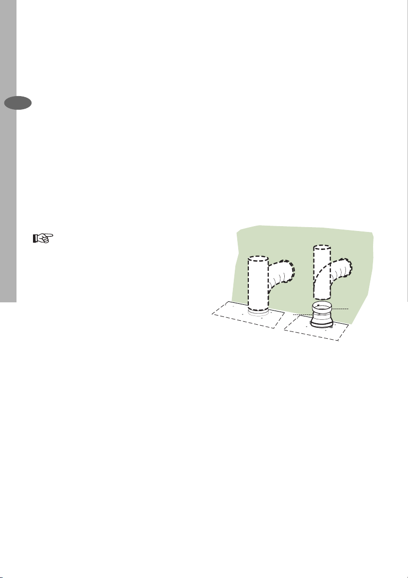
Fitting the Ducting
• Fit the ø150mm (6ins) ducting to the
spigot on top of the hood body as
illustrated.
• When using ø125mm (5ins) ducting fi t
item 9 and 10 on to the spigot on the
top of the hood body as illustrated.
• For the best performance use the
shortest possible run of ducting and
we recommend the use of rigid pipe in
preference to fl exible hose as this will
improve the fl ow of air while reducing
turbulence, which causes noise and a
loss of performance.
• If the room where the cooker hood
is to be used contains a fuel burning
appliance such as a central heating
boiler, then its fl ue must be be of the
room sealed or balanced fl ue type.
• If other types of fl ue or appliances are
fi tted ensure that there is an adequate
supply of air to the room.
• The cooker ducting when fi tted in
the extraction mode must never be
connected to central heating fl ues,
radiators or water heaters.
ø 150
ø 125
9
10
Page 23
INSTALLING THE COOKER HOOD electrolux 23
Recirculation Mode
The cooker hood is supplied specifi ed for
use in the recirculation mode, with the
charcoal fi lter fi tted.
In the recirculation mode contaminated air
is passed through the charcoal fi lter to be
purifi ed and recirculated into the kitchen
through the grille outlets on either side of
the chimney.
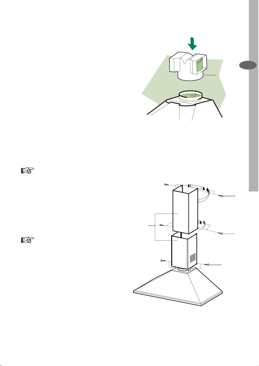
• Push fi t the air outlet connector item
15 onto the air outlet.
• Ensure the activated charcoal fi lter
has been fi tted.
Fitting the Upper Chimney
• Slightly widen the two sides of the
upper chimney and hook them behind
the brackets item 7.2.1 ensuring they
are correctly seated.
• Secure the sides to the brackets using
the 4 screws item 12c (2.9 x 9.5mm)
supplied.
Fitting the Lower Chimney
• Slightly widen the two sides of the
lower chimney and hook them
between the upper chimney and
the wall, ensuring they are correctly
seated.
• Fix the lower chimney to the hood
body using 2 screws item 12c (2.9 x
9.5mm) supplied.
• Make sure that the air outlet
connection is aligned with the
chimney outlets.
EN
15
12c
2.2
2
12c
2.1
12c
Page 24

electrolux 24
Page 25

electrolux 25
Page 26

electrolux 26
Page 27
Page 28
www.electrolux.com
436003741_01 - 070321
 Loading...