

Electrolux EFC6426, EFC9426, u0001u0004u0005u0006u0007bu0001u0004u0005u0006u0007bEFCR 942, EFCR 942 User Manual
Page 1

Instruktionsbok, Bruksanvisning, Brugsvejledning
EFCR 942
EFC 9426 - 6426
Käyttöohje, User Manual, Gebrauchsanweisung
N
DK
S
FIN UK D
Page 2
42
S Innehållsförteckning ............................................................. 2
N Innholdsfortegnelse ............................................................ 12
DK Indholdsfortegnelse ............................................................ 22
FIN Sisällysluettelo .................................................................. 32
UK Contents ............................................................................ 42
D Inhalt .................................................................................. 52
Contents
Information about safety ........................................................................................ 42
Description of the hood.......................................................................................... 44
How to use the hood ..............................................................................................45
Maintenance and cleaning. ....................................................................................46
When the hood does not work. ..............................................................................47
Accessories:........................................................................................................... 47
Technical data ........................................................................................................ 48
Installation .............................................................................................................. 48
Information about safety
The hood is destined uniquely for non-professional use in a domestic setting. It complies with international
safety quality regulations and requisites. The safety measures cannot, however, eliminate all risks of accidents.
Read the instructions, suggestions, and warnings carefully before installing and starting to use the hood.
Pay particular attention to the paragraphs with a triangular warning symbol to avoid damage to people or
objects. We recommend conserving the instructions booklet that must be supplied in case of sale or cession of
the hood to third parties.
For the installer
When used as an extractor unit, the hood must be
fitted with a 150mm diameter hose.
Attention: The hose is not supplied and must
be purchased separately.
The hood must be installed at a distance of least
50 cm above the cooking top or electric plates,
or at least 65 cm above gas rings or gas tubes.
The hood is considered disconnected only when
the plug is disconnected or the fuse removed.
Observe the rules and regulations concerning
the elimination of fumes. The waste disposal
tube of the hood cannot therefore be connected
to a conduit that is used for removing fumes
from equipment supplied by power different to
electricity, e.g. a boiler or a fireplace.
If the instructions for installation for the gas
hob specify a greater distance, this must be
adhered to.
The national Standard on fuel-burning systems
specifies a maximum depression of 0.04 mbar in
such rooms.
The air outlet must not be connected to chimney
flues or combustion gas ducts. The air outlet must
under no circumstances be connected to ventilation
ducts for rooms in which fuel-burning appliances
are installed.
The air outlet installation must comply with the
regulations laid down by the relevant local
authorities.
When the unit is used in extraction mode, a
sufficiently large ventilation hole must be provided,
with dimensions that are approximately the same
as the outlet hole.
National and regional building regulations impose
a number of restrictions on using hoods and fuelburning appliances connected to a chimney, such
as coal or oil room-heaters and gas fires, in the
same room.
Hoods can only be used safely with appliances
connected to a chimney if the room and/or flat
(air/environment combination) is ventilated from
outside using a suitable ventilation hole approximately 500-600 cm
2
large to avoid the possibility
of a depression being created during operation of
the hood.
If you have any doubts, contact the relevant
controlling authority or building inspectors office.
Since the rule for rooms with fuel burning
appliances is outlet hole of the same size as the
ventilation hole, a hole of 500-600 cm
2
, which is
to say a larger hole, could reduce the performance of the extractor hood.
If the hood is used in its recirculation mode, it will
operate simply and safely in the above conditions
Page 3

43
without the need for any of the aforementioned
measures.
When the hood is used in its extraction mode, the
following rules must be followed to obtain optimal
operation:
short and straight outlet hose
keep bends in outlet hose to a minimum
never install the hoses with an acute angle,
they must always follow a gentle curve.
keep the hose as large as possible (preferably
the same diameter as the outlet hole).
the length should be no more than:
3 metres with one 90° bend
2 metres with two 90° bends
Bends of more than 90° will reduce the
efficiency of the hood and reduce the airflow.
Failure to observe these basic instructions will
drastically reduce the performance and increase
the noise levels of the extractor hood.
For the user
The cooker hood is designed to extract unpleasant
odours from the kitchen, it will not extract steam.
Always cover lighted elements, to prevent excess
heat from damaging the appliance. In the case
of oil, gas and coal fired cookers it is essential to
avoid open flames.
Also, when frying, keep the deep frying pan on
the cooker top/cooker under careful control.
The hot oil in the frying pan might ignite due to
overheating.
The risk of self-ignition increases when the oil
being used is dirty.
It is extremely important to note that overheating
can cause a fire.
Never carry out any flambé cooking under
the hood.
Always disconnect the unit from the power
supply before carrying out any work on the
hood, including replacing the light bulb (take
the cartridge fuse out of the fuse holder or switch
off the automatic circuit breaker).
It is very important to clean the hood and
replace the filter at the recommended
intervals. Failure to do so could cause grease
deposits to build up, resulting in a fire hazard.
The appliance is not intended for use by young
children or infirm persons without supervision.
Older children must be supervised if using the
appliance.
Young children should be supervised to ensure
that they do not play with the appliance.
WARNING - Ensure that the appliance is
switched off before replacing the lamp to avoid
the possibility of electric shock.
This appliance is marked according to the
European directive 2002/96/EC on Waste Electrical
and Electronic Equipment (WEEE).
By ensuring this product is disposed of correctly,
you will help prevent potential negative
consequences for the environment and human
health, which could otherwise be caused by
inappropriate waste handling of this product.
The symbol
on the product, or on the
documents accompanying the product, indicates
that this appliance may not be treated as household
waste. Instead it shall be handed over to the
applicable collection point for the recycling of
electrical and electronic equipment.
Disposal must be carried out in accordance with
local environmental regulations for waste disposal.
For more detailed information about treatment,
recovery and recycling of this product, please
contact your local city office, your household waste
disposal service or the shop where you purchased
the product.
Page 4
44
Description of the aspiration hood
Functions
Two systems are possible:
Aspiration of the air outside with a flue
assembly (optional) and a waste disposal tube.
Recirculation of the air using an active carbon
filter (optional).
Attention! The EFCR 143 model has been
designed exclusively in the aspiration mode and
must be connected to an external aspiration
system.
Attention! The EFCR 942 model has been
designed exclusively in the aspiration mode and
must be connected to an external aspiration
system.
The aspiration hood cannot be connected to
the fume tubes of other apparatuses
functioning with sources of power other than
electricity, e.g. a boiler or a fireplace.
Accessories
The following accessories are supplied together
with the hood:
1 cover complete with commands, illumination
and ventilator motor (the EFCR 942 model is
without a motor and must be connected to an
external system of aspiration);
A telescopic flue that includes an upper and a
lower U section;
1 montage template;
1 support for the flue complete with ventilation
system;
1 deflector (concerns only the EFC 9426-
6426 model);
1 plastic envelope containing the montage and
documentation material.
The following accessories can be obtained from
your retailer:
Active carbon filter. Type 160. When the
hood is connected to the recirculation system
an active carbon filter needs to be used.
D
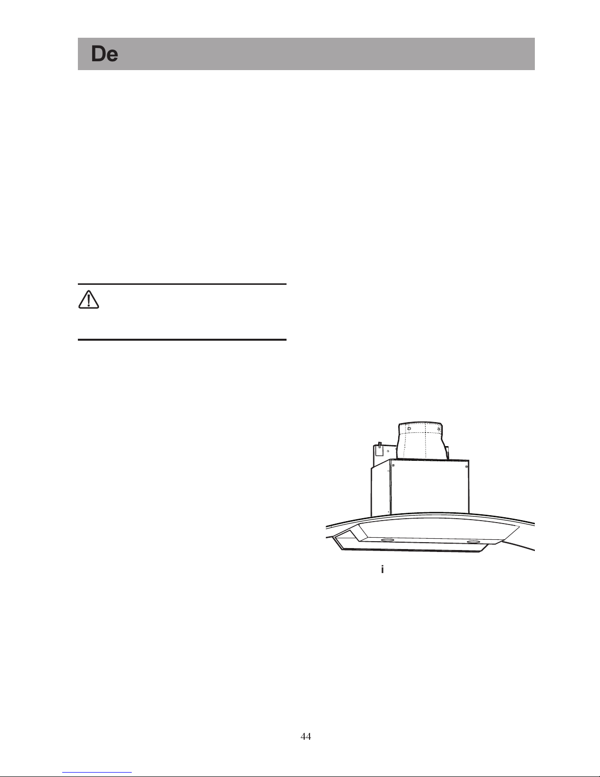
Fig. 1
A
Aspiration version
The air is evacuated by a tube that must be
connected to connection flange A. Fig. 1
The hole must have the same diameter as the
waste disposal tube in order to obtain an
optimal result.
Air recirculating version
(filtering)
Attention! The EFCR 942 model has been
designed exclusively in the aspiration mode and
must be connected to an external aspiration
system.
The air is filtered through the active carbon
filter and brought back into the kitchen through
the upper grill of the evacuation tube.
The filtering version requires an original Type
160 Electrolux filter.
Page 5
45
How to use the hood
Control Panel
The best results are obtained using low speed with
normal cooking and a higher speed in the case of
a particular concentration of fumes.
We advise switching the hood on a few minutes
before starting to cook so as to obtain a vacuum
in the kitchen and to leave it working at the end of
cooking for another 15 minutes until all fumes and
odours have disappeared. The commands are on
the front panel of the hood.
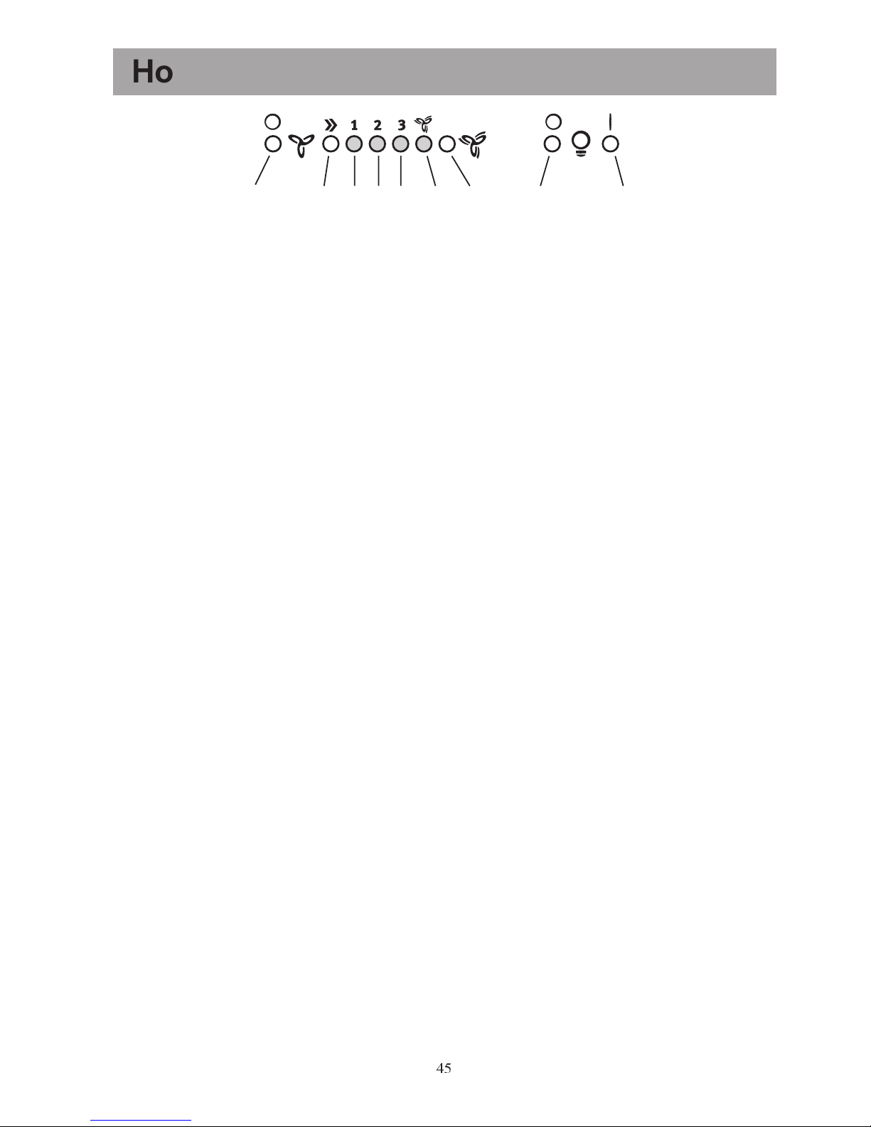
A Motor switch-off key
B Hood switch-on key and speed selection 1-
2-3-1-2
C 1st speed indicator 1 (LED)
D- 2nd speed 2 and saturation of the anti-fat filter
indicator (LED)
E Intensive speed indicator
F Intensive speed key (LED). Intensive speed
lasts 5 minutes. If the hood is working when
intensive speed is started, it will return to the
previously set speed once the time has passed
(5 minutes). If the hood is off when intensive
speed is started, it switches off automatically at
the time limit (5 minutes). It is, for example,
opportune to use intensive speed to evacuate
odours after finishing cooking.
H Illumination OFF key.
I Illumination ON key.
If the hood or the commands are not working,
disconnect the electricity supply for at least 5
minutes and start the apparatus again.
Control device of the saturation
of the anti-fat and active carbon
filters.
The aspiration hood is equipped with
a device that signals when the anti-fat
or active carbon filter (recirculation
with carbon filter version) needs
cleaning.
The hood is delivered from the factory without the
carbon filter and therefore the LED that signals
filter saturation is inactive.
Activate the LED as indicated below if the hood
has to be used with the carbon filter:
Press keys B and G simultaneously for three
seconds. The D anti-fat filter LED lights up and
then the E carbon filter LED as well. The LED
that signals the saturation of the active carbon filter
has been activated.
Deactivation. Press keys B and G simultaneously
for three seconds until the E carbon filter LED
switches off.
Grease filter LED (D)
The D LED begins to flash when the anti-fat filter
needs to be washed.
The anti-fat filter must be changed after about 40
hours of use. Follow the instructions for changing
the anti-fat filter.
The active carbon filter LED (E)
The E LED begins to flash when the active carbon
filter must be changed.
The anti-fat filter must be changed after about 160
hours of use. Follow the instructions for changing
the active carbon filter.
Restoring the saturation
indicator
After having carried out maintenance on the filter,
keep key A held for 3 seconds until the LED of
the anti-fat filter D or the LED of the carbon filter
E stops flashing
Attention! Restoring the saturation indicators
MUST be carried out with the hood set in Standby and therefore without disconnecting the hood
from the power supply.
Correct ventilation
A vacuum must be created in the kitchen for the
correct functioning of the hood.
It is important to keep the kitchen windows
closed and have a window open in an adjacent
room.
Important
If the hood is used together, for example, with an
open fireplace that takes air from inside the house,
a draught might occur that could bring fumes into
the room. Open a window.
This does not concern the active carbon filter
version.
Fig. 2
ABC
D
E
F
GH I
Page 6
46
Disconnect the hood from the power before any maintenance work, removing the plug or the fuse.
Clean the filter often. Deposits of fat on the filter and the sides of the evacuation conduit are a fire
danger if, for example, a ring has been forgotten and inadvertently left on (or in the case of other kinds of
overheating).
Maintenance and cleaning
Cleaning the hood
Clean the exterior of the hood with a damp cloth
and a neutral detergent.
Never use cleaning products containing corrosive
and abrasive, agents or inflammable substances.
Cleaning the grease filter
Clean the grease filter every month or every two
months, according to how long the hood is used.
The more often the filter is cleaned, the more often
will it be able to retain the fats.
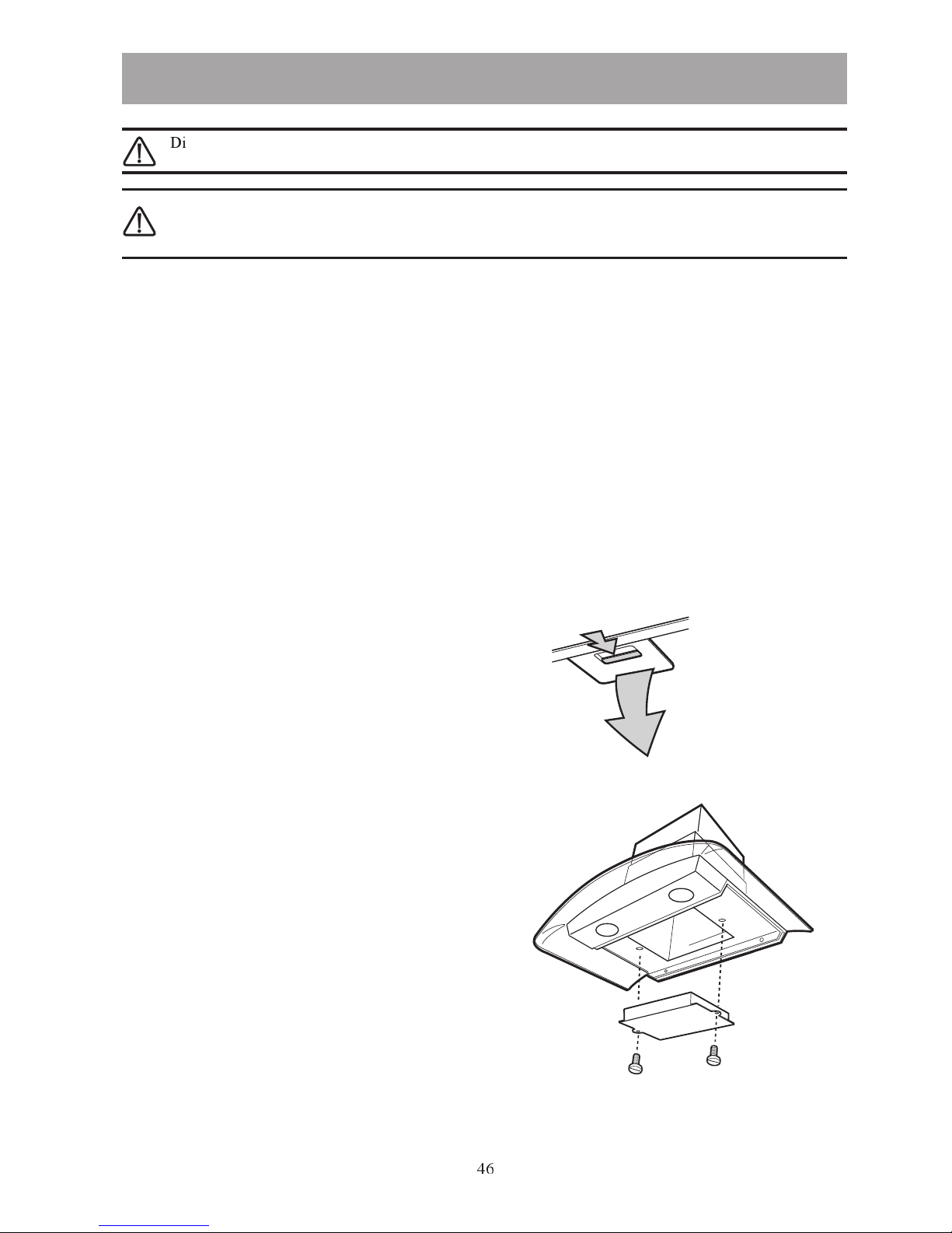
To remove the filters Fig.4:
· Press the clip on the metal anti-fat filter
backwards and remove the filter downwards.
The filter consists of aluminium reticules upon which
the fat is collected.
Clean the filter by immersing it in hot water or
putting it into the dishwasher.
Wait until the filter is dry before remounting it.
Warning! Putting the filter into the dishwasher may
fade the filter.
Active carbon filter
An active carbon filter must be used only if the hood
is used in the recirculating version (filtering).
· An original ELECTROLUX active carbon filter
must be used (it can be ordered from your
ELECTROLUX assistance service).
· This kind of filter cannot be cleaned or
regenerated.
· Normally the filter is changed every 4 months.
Fig. 4
Fig. 3
· Montage- Fig. 4.
· Remove the anti-fat filter. Remove the carbon
filter by unscrewing the two screws that fix it and
pulling downwards. ATTENTION! Do not for
get to clean the filter periodically.
· Follow the instruction in reverse to disassemble
the filter.
· Always indicate the model, and the product
and series number when you need to order
new filters. The relative data are indicated on
the plate inside the apparatus.
· Active carbon filters can be ordered from your
local dealer.
Page 7
47
MODEL
PNC
Serial No.
Lamp
Motor
When the hood does not function
If your appliance fails to work properly please carry out the following checks.
Symptom Solution
The cooker hood will not start... Check that: The hood is connected to the electricity supply.
Check that a fan speed has been selected
The cooker hood is not working Check that: The fan speed is set high enough for the task.
The grease filters are clean.
The kitchen is adequately vented to allow the entry of fresh air.
If set up for recirculation, check that the charcoal filter is still effective.
If set up for extraction, check that the ducting and outlets are not blocked.
The cooker hood has
switched off during operation...
The safety cut-out device has been tripped.
Turn off the hob and then wait for the device to reset.
If the hood has been installed below the heights indicated in the
installation instructions the motor will cut-out frequently which will
damage the hood.
If after all these checks, the problem persists, contact your local
Service Force Centre, quoting the model and serial number.
Please note that it will be necessary to provide proof of purchase
for any in-guarantee service calls.
In-guarantee customers should ensure that the above checks have
been made as the engineer will make a charge if the fault is not a
mechanical or electrical breakdown.
Accessories:
Type 160 active carbon filter
External motor (for external installation) 942 121 135
External motor (for external installation) 942 121 182
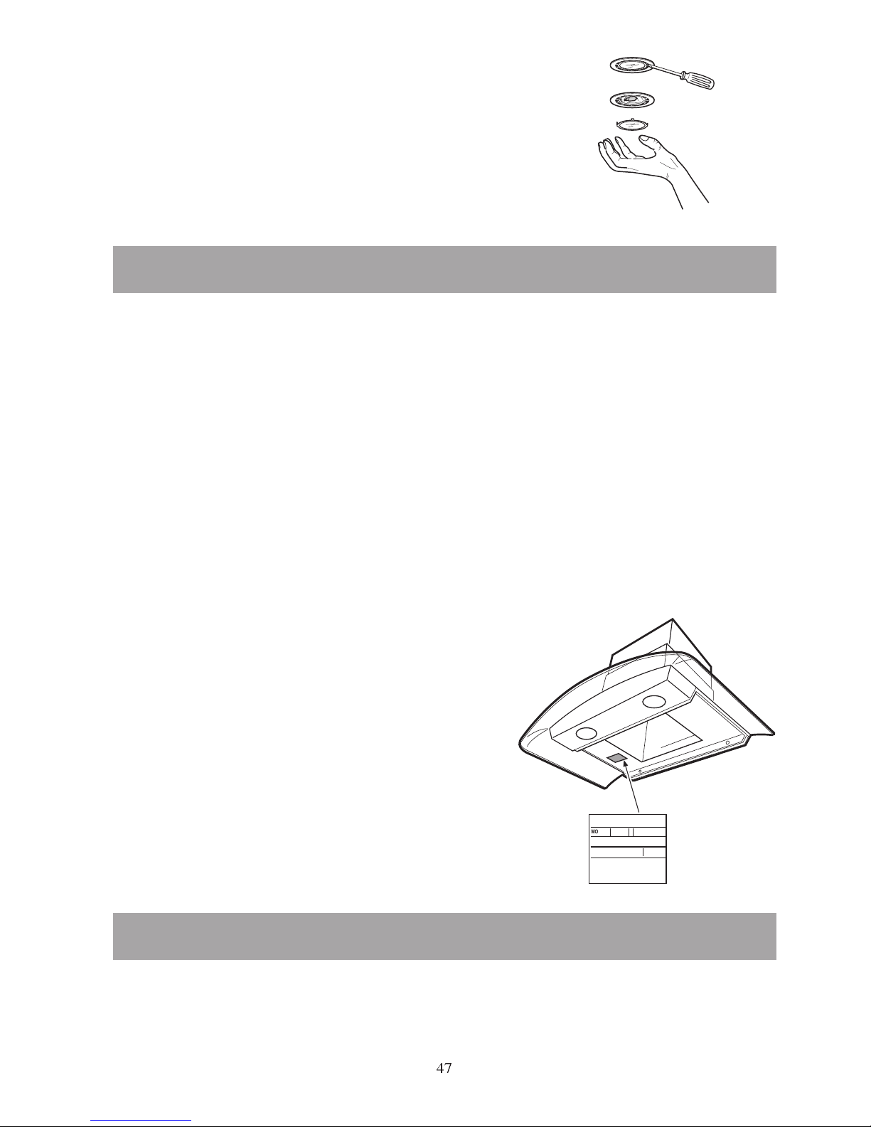
Changing the lamp
The hood must be disconnected from the power
supply when changing the lamp. Carry out the
change in this way (Fig. 5):
· Remove the protective glass of the lamp with a
screwdriver.
· Substitute the lamp with an equivalent one.
· Remount the protective glass of the lamp.
Fig. 5
Page 8
48
Installation
Opening the packaging
Warning! Check that the aspiration hood is not
damaged. Damage due to transportation must be
immediately communicated to the transport
company. Damage, defects, and eventual missing
parts must be immediately communicated to the
dealer. Dispose of the packaging material, keeping
it far from the reach of children.
Positioning
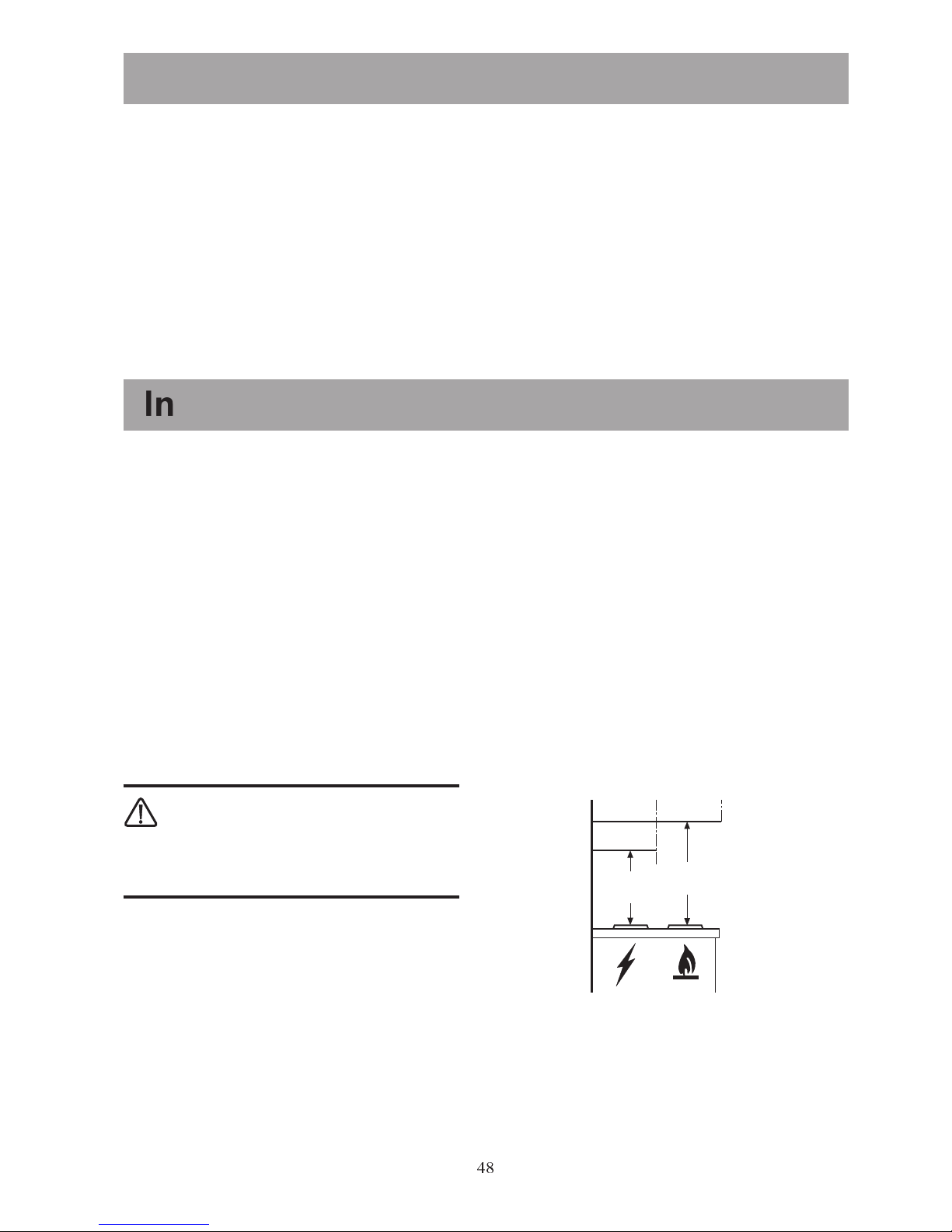
· The hood must be mounted at a distance of at
least 50 cm above the cooking top or electric
plates or at least 65 cm above gas rings or gas
pipes. Fig.6
The waste pipe of the hood cannot be
connected to a conduit that is used for
evacuating fumes of apparatuses supplied with a
different energy to electricity, e.g. a boiler or a
fireplace.
Electrical connection
The electricity socket must be positioned inside the
flue. The hood has a supply cable and a plug
provided with grounding and a voltage of 220-240V.
Technical data
EFCR 942 EFC 9426 EFC 6426
Overall dimensions (cm) Height 64 - 92 64 - 92 62 - 91
Width 89,8 89,8 59,8
Depth 50 50 50
Illumination 2 x 20 W 2 x 20 W 2 x 20 W
Grease filters 2 2 1
Voltage 220-240 V 220-240 V 220-240 V
Total Power 230 W** 200 W 200 W
**
External motor (external installation) 942 121 135
External motor (external installation) 942 121 182
Min
65 cm
Min
50 cm
Fig. 6
Page 9
49
Installation
Mounting the hood to the wall
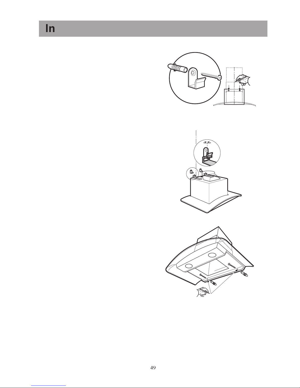
Position the holing diagram to the wall at the
correct height (fig.7). The lower corner of the
diagram corresponds to the lower corner of
the aspiration hood
There is a line on the holing template that
corresponds to the centre of the apparatus.
Trace a line up to the ceiling to facilitate the
installation of the hood (fig. 7).
Make a hole, as indicated in the diagram and
insert two wall dowels, two hooks, and two
screws (fig. 7).
Hang up the hood. Adjust the position with the
screws on the hooks of the hood (Fig. 8).
Mark the points on the wall from inside the
hood, corresponding to the holes to use for the
definitive fixing of the hood (Fig. 9).
Remove the hood.
Make two holes (Ø 8mm) and insert two
dowels (Fig. 9).
Hang the hood up again on the hooks.
Insert the definitive fixing screws from inside
the hood (Fig. 9).
Fig. 7
Fig. 8
Fig. 9
Page 10
50
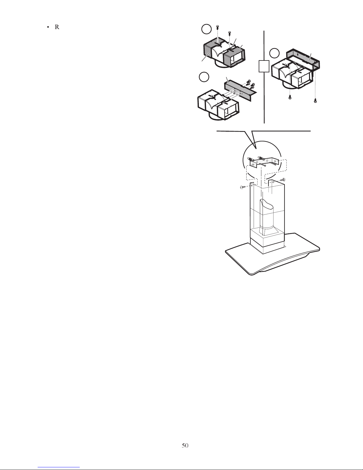
Remove the support from the telescopic flue
by unscrewing the two screws that fix it to the
flue (one per side - save the screws - Fig. 10).
Remove deflector F from the support by
unscrewing the 4 screws that fix it to the
support (save the screws - Fig.10).
Fix the telescopic flue support to the ceiling.
The support has a reference mark that must
correspond to the line previously traced on the
wall (Fig. 10).
Mark where the holes for fixing the support
should be made with a pencil, and drill (Ø 8
mm).
Insert two dowels and fix the telescopic
support with two 5x45 screws (Fig. 10).
Fix the end of the waste disposal tube onto
connection ring B and the other end to the
conduit for evacuating fumes (aspiration
version) or the connection ring of ventilator
screen F (recirculation version).
Attention! Concerns only the EFCR 942
model:
Connect the waste disposal tube to one
external aspiration unit (see following
paragraph Connection to an external motor).
Connect the electricity.
Attention! Only for the EFCR 942 model:
It is also necessary to carry out the electrical
connection to an external aspiration unit (see
following paragraph Connection to an external
motor).
Check, in the case of a non-return valve being
used, that it is functioning correctly and is not
blocked by the tube.
Fix the upper part of the hood to its support
with two screws (Fig. 10).
Slide the lower section of the flue downwards
and insert it into the apposite housing on the
upper part of the hood.
Mounting the grease filter
Position the filter at the back of the hood and
move the handle upwards until the filter is
blocked.
3,5 x 13
1
a
b
b
3,5 x 13
2
c
2,9 x 6,5
3
d
Fig. 10
B
F
Page 11
51
N
B
S
L
H05 VVF (3 x 0.75)
cable.
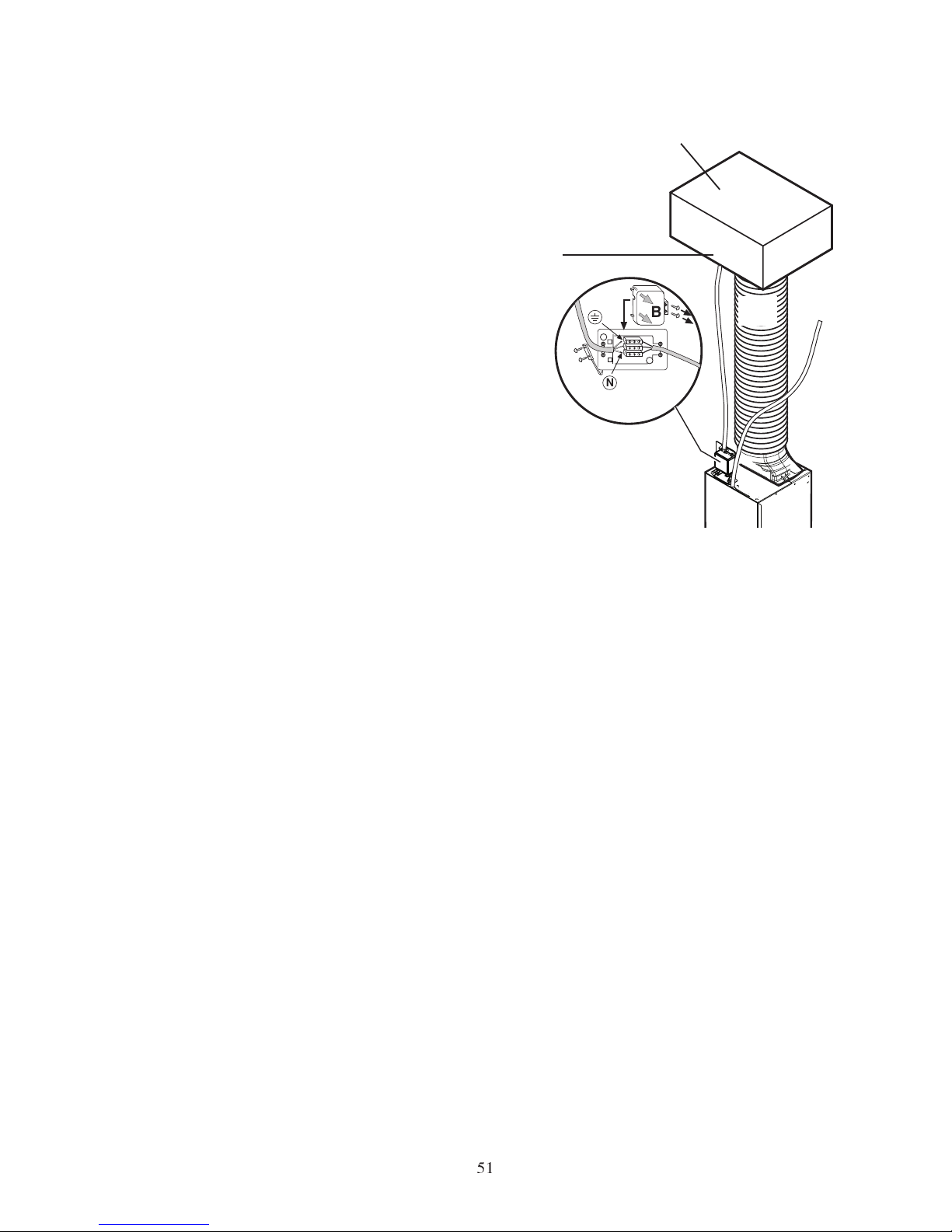
Connection to external motor
Concerns only the EFCR 942 model.
The hood is not equipped with an internal motor
and must be connected to an external motor (to
purchase separately).
The electrical connection must be carried out with
the help of suitable connections.
Attention! Use only the external motor
supplied by the constructor.
Connecting the waste disposal tube to the
external motor.
The external motor must be installed at a point
sufficiently spacious with respect to the regulations
in force.
The external motor must be connected to the
hood with a waste disposal tube with an adequate
diameter (min. 150 mm).
Note that the longer the waste disposal tube is,
the worse will be it aspiration capacity. The length
of the waste disposal tube must never, in any case,
be longer than 7 metres.
All the material necessary for connecting the hood
to the external motor (tubes, electricity cables,
etc.) is not supplied and must be purchased
separately.
Electrical connection of the external motor
· Check the position of the derivation box B
above the hood.
· Remove screws S and open the cover of box
B.
· Open the cable cover removing screws L.
· Use an H05 VVF (3 x 0.75) type cable for
connecting the hood.
· Connect the motor cable clamps to the
terminal board in derivation box B on the
hood.
· Close the cable cover with screws L.
· Close the B cover and fix the S screws.
· Connect the hood to the power supply.
Fig. 11
External motor (for external installation)
942 121 135
External motor (for external installation)
942 121 182
Page 12
LI2LBC Ed. 08/05
The Electrolux Group. The world´s No.1 choice.
The Electrolux Group is the world´s largest producer of powered appliances for kitchen, cleaning and outdoor use. More than 55 million
Electrolux Group products (such as refrigerators, cookers, washing machines,vacuum cleaners, chain saws and lawn mowers) are sold each
year to a value of approx. USD 14 billion in more than 150 countries around the world.
© Electrolux 2003
Electrolux HemProdukter AB
S-105 45 Stockholm
www.electrolux.se
Electrolux Home Products
Risløkkveien 2
0508 Oslo
Tlf: 81 53 02 22
E-mail: [email protected]
Internett: www.electrolux.no
Electrolux Husholdningsapparater A/S
Lundtoftevej 160
2800 Lyngby
Tlf: 45 87 70 88
Oy Electrolux Ab
Pakkalankuja 6
01510 VANTAA
Puh. 0200-2662 (0,1597 /min+pvm)
 Loading...