

Page 1

FOR ELECTROLUX
COOKER HOOD
EFC 630
cod. 4329083 01 - 0998
Page 2

2
Thank you for buying an Electrolux product.
To enable you to use your appliance effectively and safely, please read this instruction
book carefully before using the appliance and retain for future reference. If you require
guidance in the use of the appliance or require further information on Electrolux Products,
please contact our Customer Care Department.
Customer Care Department
Electrolux
PO Box 47
Newbury
Berkshire Tel: 01635 522799
RG14 5XL Fax: 01635 42970
To register ownership, please ensure you complete and return the guarantee card
supplied with the appliance.
Guide to use the instruction book
The following Symbols will be found in the text to guide you through the instruction book
Safety instructions
K Step by step instructions
For the User
Important Safety Information
Your Appliance
Operating Instructions
Cooker Hood Controls
To Operate
Recirculation
Extraction
Maintenance and Cleaning
External Cleaning
Metal Grease Filters
Charcoal Filters
To Remove/Replace the Charcoal Filters
Changing the Light Bulb
Something Not Working
Service and Spare Parts
Guarantee Conditions
For the Installer
Technical Information
Electrical Connections
Electrical Requirements
Electrical Connection
Installing the Cooker Hood
Installation Requirements
Unpacking
Clearance Height
Fitting the Wall Brackets
Fitting the Canopy Hood
Venting
Recirculation
Fitting the Chimney Stack
Service Force Centres
To register ownership, please ensure
you complete and return the guarantee
card supplied with the appliance.
Page 3

3
IMPORTANT SAFETY INFORMATION
These warnings are provided in the interests of your safety. Ensure that you understand them
all before installing or using this appliance. Your safety is of paramount importance. If you are
unsure about any of the meanings of these warnings contact the Customer Care Department.
■ Installation
• Any installation work must be undertaken by
a qualified electrician or a competent
person.
• This hood must be installed in accordance
with the installation instructions and all
measurements must be adhered to.
• If the cooker hood is installed for use above
a gas appliance then the provision for
ventilation must be in accordance with the
Gas Safety Codes of Practice BS.6172,
BS.5440 and BS.6891 (Natural Gas) and
BS.5482 (LP Gas) 1994, the Gas Safety
(Installation & Use) Regulations, the Building
Regulations issued by the Department of the
Environment, the Building standards
(Scotland) (Consolidated) Regulations
issued by the Scottish Development
Department.
• The fan motor of this cooker hood
incorporates a cut-out device which will
operate if the cooker hood is installed below
the minimum height recommended under
section ‘Clearance Height’, or if the motor
becomes overheated. If the cut-out device is
activated, switch off the fan motor and allow
the cooker hood to cool. The cut-out device
will reset itself when the fan motor has
cooled significantly.
• It is dangerous to alter the specifications or
modify this product in any way.
• When installed between adjoining wall
cabinets the wall cabinets must not overhang
the hob.
• If the room where the hood is to be used
contains a fuel burning appliance such as a
central heating boiler then its flue must be of
the room sealed or balanced flue type.
• If other types of flue or appliances are fitted
ensure that there is an adequate supply of air
to the room.
• The ducting system for this appliance must
not be connected to any existing ventilation
system which is being used for any other
purpose.
• Do not install above a cooker with a high
level grill.
■ Child Safety
• This appliance is designed to be operated by
adults. Children should not be allowed to
tamper with the controls or play with the
appliance.
■ During Use
• This product is for domestic use only.
• Never leave frying pans unattended during
use as over-heated fats and oils might catch
fire.
• Never do flambé cooking under this cooker
hood.
• Do not leave naked flames under the hood.
■ Maintenance and Service
• This appliance can be a hazard if the
synthetic paper and charcoal filters are not
replaced as recommended.
• Under no circumstances should you attempt
to repair the appliance yourself. Repairs
carried out by inexperienced persons may
cause injury or more serious malfunction.
Refer to your local Electrolux Service Force
Centre. Always insist on genuine spare
parts.
Page 4
4
YOUR APPLIANCE
OPERATING INSTRUCTIONS
The cooker hood is designed to extract unpleasant
odours from the kitchen, it will not extract steam.
The appliance can be installed to recirculate or
extract contaminated air.
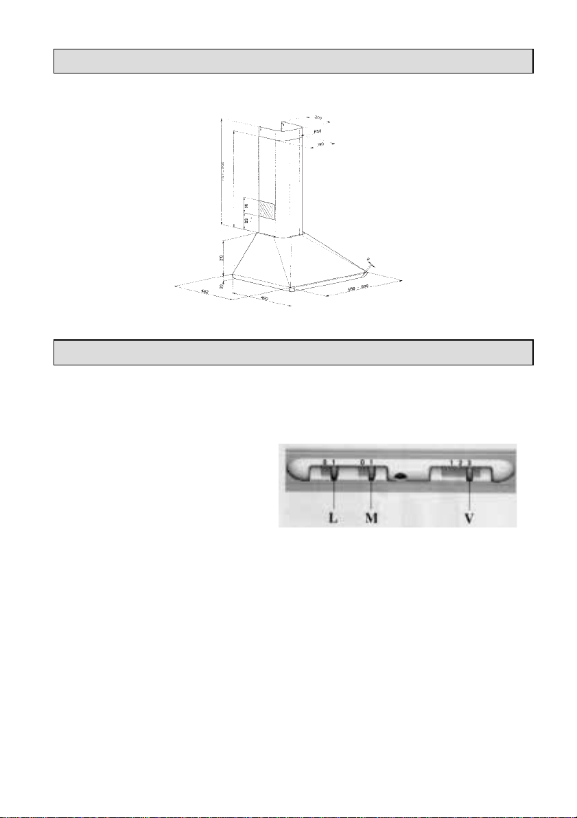
Cooker Hood Controls
The hood functions are controlled by three
slide switches located to the right on the
underside of the hood immediately in front of
the metal grease filter.
Worktop Lighting
The switch marked with lamp symbol operates
the worktop lighting
L. 0 - Off
1 - On
Fan Control
M. Fan ON/OFF control
0 - Off
1 - On
V. Fan Speed Control
1 - Low
2 - Normal
3 - Boost
To Operate
Select the required fan speed and light if
required.
360
360 - 760
Page 5

5
Recirculation
The air is cleaned by passing through the filters
and then back into the kitchen.
Extraction
The contaminated air enters the hood passing
through the grease filter and out through the
ducting into the atmosphere
To obtain the best performance it is advisable
to switch on the hood a few minutes before
you start cooking and leave it running for
approximately 15 minutes after finishing.
When used in the ducting mode the
charcoal filters are not required.
Never do flambé cooking under this
cooker hood.
Never leave frying pans unattended
during use as over-heated fats and oils
can catch fire.
Do not leave naked flames under the
cooker hood.
Ensure heating areas on your hob are
covered with pots and pans when using
the hob and cooker hood
simultaneously.
Page 6
6
MAINTENANCE AND CLEANING
Before carrying out any maintenance or
cleaning isolate the cooker hood from the
mains supply.
The cooker hood must be kept clean, as a
build up of grease or fat can be a fire
hazard
External Cleaning
Wipe the cooker hood frequently with warm
soapy water using a mild detergent.
Never use scouring pads or abrasive
cleaners.
Never use excessive amounts of water
when cleaning particularly around the
control panel.
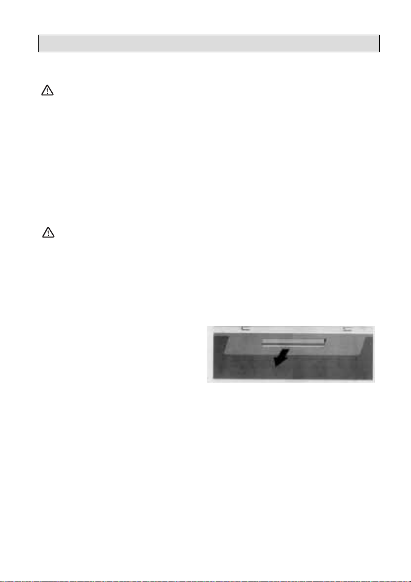
Metal Grease Filters
The grease filter absorbs grease and dust
during cooking to help keep the appliance
clean inside, and should be cleaned
approximately once every month
or more often if the hood is used for
more than 3 hours a day.
K
Remove the metal grease
filters one at a time by:
Releasing the catches on the filters,
the filters can now be removed.
The metal grease filters should be washed, by
hand, in mild soapy water or in a dishwasher.
Allow to dry completely before replacing.
Page 7
7
Charcoal Filters
In the recirculation mode the charcoal filters
absorb smells an unwanted odours.
The charcoal filters cannot be cleaned, we
recommend they should be replaced
approximately every three months or more
often if the hood is used for more than three
hours per day.
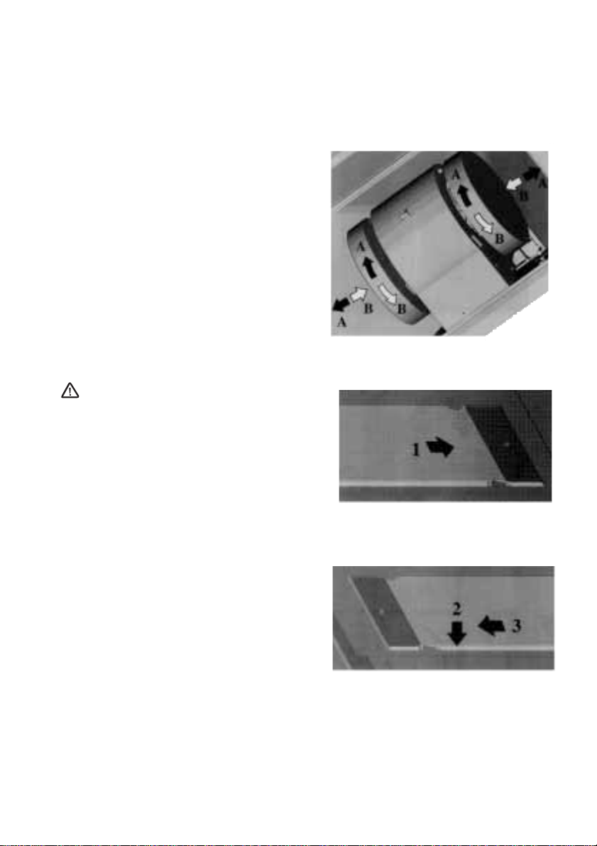
K
To Remove/Replace the Charcoal
Filters
1. First remove the metal grease filters.
2. Twist the charcoal filter anti-clockwise
and remove.
3. To replace the charcoal filters, remove
the metal grease filters.
4. Place one filter over the inlet grille at
either end of the fan housing and twist
into position.
This appliance can be a fire hazard if the
grease and charcoal filters are not
cleaned and replaced as recommanded.
K
Changing the Light Bulb
1. Loosen and remove the screws and
brackets retaining the glass cover.
2. Lever out the brackets and slide the glass
cover to the right.
3. When the cover has cleared the left hand
lugs, lower the left hand edge while slide
the cover to the left.
If the light bulb fails to function check that
the bulb is fully screwed into the holder.
If bulb failure has occurred then it should be
replaced with a 220-240 Volt 40 W clear
cylindrical shape bulb with a small E14
screw thread.
Replacement filters and light bulbs can be
obtained from your local Service Force
Centre.
Page 8

8
SOMETHING NOT WORKING
If, having followed these instructions carefully, your cooker hood fails to work properly please carry out
the following checks.
Symptom Solution
The cooker hood will not start • Check the hood is connected to the
electricity supply.
• Make sure the switch is in the ‘ON’ position.
The cooker hood is not working effectively • The fan speed is set high enough for
the task
• The grease filter is clean.
• The kitchen is adequately vented to
allow the entry of fresh air.
• If set up for recirculation, check that the
charcoal filter is still effective.
• If set up for extraction, check that the
ducting and outlets are not blocked.
The cooker hood has switched off during • The safety cut-out device has been tripped.
operation • Tum off the hob and then wait for the device
to reset.
If after all these checks, the fault persists,
contact your local Service Force Centre,
quoting the model and serial number.
Please note that it will be necessary to
provide proof of purchase for any
in-guarantee service calls.
In-guarantee customers should ensure
that the above checks have been made as
the engineer will make a charge if the fault
is not a mechanical or electrical
breakdown.
SERVICE AND SPARE PARTS
If you require an engineer or spare parts
contact your local Service Force Centre by
telephoning:
0990 929929
Your telephone call will be routed to your local
Service Force Centre. The addresses are
listed in the back of the book.
For general assistance with your appliance or
for further information on Electrolux products
please contact our Customer Care Department.
Customer Care Department,
Electrolux
PO Box 47
Newbury
Berkshire RG14 5XL
Tel: 01635 522 799
Page 9

9
GUARANTEE CONDITIONS
We, Electrolux Ltd., undertake that if within twelve months of the date of the purchase this Electrolux
buill-in appliance or any part thereof is proved to be defective by reason only of faulty workmanship or
materials, the company will, at our option repair or replace the same FREE OF ANY CHARGE for
labour, materials or carriage on condition that:
• The appliance has been correctly installed and used only on the electrical supply stated on the
rating plate.
• The appliance has been used for normal domestic purposes only, and in accordance with the
manufacturer’s operating and maintenance instructions.
• The appliance has not been serviced, maintained, repaired, taken apart or tampered with by any
person not authorised by us.
• All service work under this guarantee must be undertaken by Electrolux Service Force Centre.
• Any appliance or defective part replaced shall become the property of this company.
Home visits are made between
8.30am and 5.30pm Monday to Friday. Visits may be available
outside these hours in which case a premium will be charged.
EXCLUSIONS
This Guarantee does not cover:
• Damage or calls resulting from transportation, improper use or neglect, the replacement of any lilght
bulbs or removable parts of glass or plastic.
• Costs incurred for calls to put right appliances improperly installed or calls to appliances outside the
United Kingdom.
• Appliances found to be in use within a commercial environment, plus those which are the subject of
rental agreements.
• Products of Electrolux manufacture which are not marked by Electrolux Ltd.
This guarantee is in addition to your statutory and legal rights.
ELECTROLUX EUROPEAN GUARANTEE
If you should move to another country within Europe then your guarantee moves with you to your new
home subject to the following qualifications:
• The guarantee starts from the date you first purchased your product.
• The guarantee is for the same period and to the same extent for labour and parts as exists in the
new country of use for this brand or range of products.
• This guarantee relates to you and cannot be transferred to another user.
• Your new home is within the European Community (EC) or European Free Trade Area.
• The product is installed and used in accordance with our instructions and is only used domestically,
i.e. a normal household.
Before you move please contact your nearest Customer Care Centre, listed below, to give
them details of your new home. They will then ensure that the local Service Organisation is
aware of your move and able to look after you and your appliances.
France Senlis +33 (0)3 44 62 22 22
Germany Nurnberg +49 (0)911 323 2600
Italy Pordenone +39 (0)1678 47053
Sweden Stockholm +46 (0)20 78 77 50
UK Newbury +44 (0)1635 522 799
Page 10

10
INSTALLATION INSTRUCTIONS
It is dangerous to alter the specifications or attempt to modify this product in any way.
Technical Information
DIMENSIONS HEIGHT CANOPY: 24cm
HEIGHT CHIMNEY - UPPER SECTION 40cm
LOWER SECTIN 36cm
WIDTH CANOPY 60cm
DEPTH: 49cm
ELECTRICAL SUPPLY: Voltage (50Hz) 220-240 V
POWER CONSUMPTION: 225W
FAN MOTOR: 145W
LAMP: 2 x 40 80W
SUITABLE FOR INSTALLATION
ABOVE: ELECTRIC HOB: 7KW (max)
GAS HOB: 10KW (max)
SLOT-IN GAS COOKER 13.5KW (max)
SLOT-IN ELECTRIC COOKER 12.4KW (max)
Note: CE Marking certifies that this appliance complies with the requirements laid down in EEC directive 89:336. (Electromagnetic compatibility)
and subsequent modifications and Low Voltage directive 72/23/E.
ELECTRICAL CONNECTIONS
This appliance must be earthed
Electrical Requirements
Any permanent electrical installation must
comply with the latest I.E.E. Regulations and
local Electricity Board regulations. For your own
safety this should be undertaken by a qualified
electrician e.g. your local Electricity Board, or a
contractor who is on the roll of the National
Inspection Council for Electrical Installation
Contracting (NICEIC).
Electrical Connection
Before connecting to the mains supply ensure
that the mains voltage corresponds to the
voltage on the rating plate inside the cooker
hood.
This appliance is fitted with a 3 core mains
cable and must be permanently connected to
the electricity supply via a double-pole switch
having 3mm minimum contact gap on each
pole. ASwitched Fuse Connection Unit to
BS1363 Part 4, fitted with a 3 Amp fuse, is a
recommended mains supply connection
accessory to ensure compliance with the Safety
Requirements applicable to fixed wiring
instructions.
This appliance conforms to BS 800: 1988 and
EEC Directive No. 78 308 regarding
suppression of radio and television
interference.
Page 11

11
INSTALLING THE COOKER HOOD
Please ensure that when the appliance is
installed it is easily accessible to an
engineer in the event of a breakdown.
All installations must comply with the
local authorities requirements for the
discharge of exhaust air.
Incorrect installation may affect the
safety of this cooker hood.
Installation Requirements
Before installation check the wall to
which the cooker hood is to be fitted for
electric cables, water pipes or gas.
This cooker hood is designed to be fixed to
any rigid vertical surface over a cooking area,
and can be used in the extraction (ducted to
the outside) or recirculation mode.
The installation work must be undertaken by a
qualified and competent person. The
manufacturer disclaims any responsability for
damage due to incorrect installation of the
cooker hood or if the hood is not installed in
compliance with relevant regulations
controlling this type of installation.
Unpacking
The EFC630 is supplied with the following
components for installation:
•
Canopy (C), including controls, worktop
illumination and fan unit.
• U-shaped upper chimney section (S)
• U-shaped lower chimney section (I)
• Recirculation grilles (G)
• Reduction flange 150-120mm dia (K)
• Recirculation spigot (R)
• Wall fixing brackets for (1)
• Wall fixing brackets for (2)
• Rawl plugs
• Fixing screws
• 120-125mm ducting collar
Page 12

12
Clearance Height
The cooker hood is designed to be fitted over
a cooking appliance at the clearance heights
stated, providing the maximum output of the
appliance beneath does not exceed the
maximums quoted in the Technical
Specifications.
If the output of the appliance below the cooker
hood exceeds the maximum outputs quoted,
please refer to the cooker manufacturer’s
installation instructions.
A minimum clearance height of 650mm (25
1
/2”)
is required when installed above a
built-in electric hob, or 700mm (27
1
/2”) when
installed above a built-in gas hob.
A minimum clearance height of 685mm (27”)
is required when installed above a slot-in
electric cooker, or 787mm (30
1
/2”) when
installed above a slot-in gas cooker.
When installed between adjoining wall
cabinets, the wall cabinets must not overhang
the hob and the distance between the
underside of the cabinet and the worktop must be
450mm. If the height of the wall cabinet is
less than 450mm, a gap of 50mm must be
maintained either side of the hob.
This cooker hood must not be installed
above a cooking appliance with a high
level grill.
K
Fitting the Wall Brackets
1. Draw a vertical line on the wall from the
centre of the cooking appliance up to the
ceiling, using a spirit level and marking
pen. This is to ensure the correct vertical
alignment of the appliance.
2. Mark the centre positions Y for the wall
bracket keyhole fixing screws item 1
(lower fixing bracket) at 100mm either
side of the vertical line. Ensure that the
distance between the lowest point of the
hood and the cooking appliance beneath
meet the clearance requirements quoted
above. * Clearance height as specified above
A: Built-in Electric Hob: 650mm minimum clearance
B: Built-in Gas hob: 700mm minimum clearance
C: Slot-in Electric Cooker: 685mm minimum clearance
D: Slot-in Gas Cooker: 787mm minimum clearance
Hob
Page 13

13
3. Draw a horizontal line through the vertical
line 15mm from the ceiling. Place one of
the two
upper brackets (item 2) over the
line. Ensure the bracket is level and mark
the centres for the keyhole fixing screws
55mm either side of the vertical line.
4. Draw a horizontal line through the vertical
line for the second
upper brackets (item 2)
at X. X is the distance between the centre
of the top and bottom fixing holes on the
upper chimney section. Ensure the line is level.
5. Place the second bracket (item 2) over
the line, and mark the centres for the
keyhole fixing screws 55mm either side of
the vertical line.
6. Drill the holes for the wall bracket fixing
screws using an 8mm drill and fix the wall
brackets items 1 and 2 using the rawl
plugs and screws provided.
Note:
If the hood is to be installed onto a
hollow construction or plaster or partition
board wall then special fixing will be
required (not supplied).
K
Fitting the canopy hood
1. Hook the canopy hood C, into the wall
fixing brackets ensuring the security fixing
screws align with the holes in the centre
of the back panel as illustrated.
2. Insert the two M4 x 25m canopy
adjustment screws, into the wall brackets,
from the underside of the hood.
3. The canopy can be aligned and adjusted
in height by using the two adjustment
screws (W).
4. Before fitting the chimney to the canopy
make the electrical connection as
described in the sectione titled
“ELECTRICAL CONNECTION”.
5. When the electrical connection has been
made, test the worktop lighting and the
three speed fan.
Page 14

14
Venting
The hood is more effective when used
in the extraction mode (ducted to the
outside).
Venting kits may be purchased through your
retailer or DIY store, and must be ducted
to an outside vent of 150mm (5ins) or 125mm
(5ins).
The best performance will be achieved by using the
largest diameter ducting available.
Where flexible ducting is fitted the length
should be no more than:
3 metres with one 90° bend
2 metres with two 90° bends
Bends of more than 90° will reduce the
efficiency of the hood and reduce the airflow.
The ducting used must be manufactured
from fire retardant material conforming
to the relevant British Standard or
DIN 4102-B1
When the hood is ducted to the outside the
charcoal filters must be removed.
Recirculation
If you are using the hood for recirculating,
ensure the charcoal filters are in position
following the instructions contained in the
section (To Remove/Replace the Charcoal
Filters).
Page 15

15
K
Fitting the Chimney Stack
The chimney stack consists of two 2 sections.
1. Fit the upper section (S) first. Expand the
chimney slightly to allow it to be fitted
over the wall brackets, and then secure
the upper section using the 4 self
tapping screws provided.
2. Fit the lower chimney section (I) as
above ensuring the base of the
chimney is fitted correctly into the
recess around the top of the canopy
as illustrated.
3. When the chimney stack has been
installed, fit the two venting grilles
into the apertures located on either
side of the lower chimney stack.
The grilles are marked with two
arrows and should be fitted with one
arrow pointing upwards and the other
towards the front.
Note:
When the cooker hood is used in
recirculation mode, ensure the
grilles are properly secured to the
recirculation spigot R, as illustrated.
Page 16

16
ELECTROLUX SERVICE FORCE
To contact your local Electrolux Service Centre telephone 0990 929929
CHANNEL ISLANDS
GUERNSEY Guernsey Electricity
PO Box 4
Vale, Guernsey
Channel Islands
JERSEY Jersey Electricity Company
PO Box 45
Queens Road
St Helier
Jersey
Channel Islands
JE4 8NY
SCOTLAND
ABERDEEN 8 Cornhill Arcade
(M05) Cornhill Drive
Aberdeen
AB2 5UT
AUCHTERMUCHY 33A Burnside
(M03) Auchtermuchy
Fife KY14 7AJ
BLANTYRE Unit 5
(M07) Block 2
Auchenraith Ind Estate
Rosendale Way
Blantyre G72 0NJ
DUMFRIES 93 Irish Street
(M01) Dumfries
Scotland
DG1 2PQ
DUNOON Briar Hill
(M67) 7 Hill Street,
Dunoon
Argyll PA23 7AL
GLASGOW 20 Cunningham Road
(M04) Clyde Estate
Rutherglen
Glasgow G73 1PP
INVERNESS Unit 3B
(M06) Smithton Indust. Est.
Smithton
Inverness
IV1 AJ
ISLE OF ARRAN Arran Domestics
Unit 4 The Douglas Centre
Brodick
Isle of Arran
(OWN SALES) KA27 8AJ
ISLE OF BARRA J Zerfah
244 Bruernish
Isle of Barra
(OWN SALES) Western Islands
HS9 5QY
ISLE OF BUTE Walker Engineering
(M66) Glenmhor
Upper Serpentine Road
Rothesay
Isle of Bute
PA20 9EH
ISLE OF LEWIS ND Macleod
(M69) 16 James Street
Stornoway
Isle of Lewis PA87 2QW
KELSO 2-8 Wood Market
(M08) Kelso
Borders TD5 7AX
ORKNEY Corsie Domestics
(M65) 7 King Street
Kirkwall
Orkney KW15
SHETLAND Tait Electronic Systems Ltd.
Holmsgarth Road
Lerwick
(OWN SALES) Shetland ZE1 0PW
SHETLAND Bolts Shetland Ltd.
26 North Road
Lerwick
(OWN SALES) Shetland ZE1 0PE
WHALSAY Leask Electrical
Harlsdale
Symbister, Whalsay
(OWN SALES) Shetland ZE2 9AA
NORTHERN IRELAND
BELFAST Owenmore House
(M27) Kilwee Industrial Estate
Upper Dunmury Lane
Belfast
BT17 0HD
Page 17

17
ELECTROLUX SERVICE FORCE
To contact your local Electrolux Service Centre telephone 0990 929929
WALES
CARDIFF Guardian Industrial Estate
(M28) Clydesmuir Road
Tremorfa, Cardiff
CF2 2QS
CLYWD Unit 6-7 Coed - Parc
(M14) Abergele Road
Rhuddlan
Clwyd
Wales LL18 5UG
OSWESTRY Plas Flynnon Warehouse
(M17) Middleton Road
Oswestry
SY11 2PP
HAVERFORDWEST Cromlech
(M75) Amerlston
Haverfordwest
SA62 5DS
DYFED Maes Y Coen
(M77) High Mead
Llanybydder
Dyfed
SA40 9UL
NORTH EAST
GATESHEAD Unit 356a
(M39) Dukesway Court
Dukesway
Team Valley
Gateshead
NE11 0BH
GRIMSBY Unit 2
(M42) Cromwell Road
Grimsby
South Humberside DN31
2BN
HULL Unit 1
(M41) Boulevard Industrial Estate
Hull HU3 4AY
LEEDS 64-66 Cross Gates Road
(M37) Leeds
LS15 7NN
NEWTONA YCLIFFE Unit 16
(M45) Gurney Way
Aycliffe Ind Estate
Newton Aycliffe
DL5 6UJ
SHEFFIELD Pennine House
(M38) Roman Ridge Ind.
Roman Ridge Road
Sheffield
S9 1GB
NORTH WEST
BIRKENHEAD 1 Kelvin Park
(M11) Dock Road
Birkenhead
L41 1LT
CARLISLE Unit 8
(M10) South John Street
Carlisle
CA2 5AJ
ISLE OF MAN South Quay Ind Estate
(M64) Douglas
Isle of Man
LIVERPOOL Unit 1
(M15) Honeys Green Precinct
Honeys Green Lane
Liverpool
L12 9JH
MANCHESTER Unit 30, Oakhill Trading
(M09) Estate
Devonshire Road
Worsley
Manchester
M28 3PT
PRESTON Unit 250
(M13) Dawson Place
Walton Summit
Bamber Bridge
Preston
Lancashire PR5 8AL
STOCKPORT Unit 20 Haigh Park
(M16) Haigh Avenue
Stockport SK4 1QR
Page 18

18
ELECTROLUX SERVICE FORCE
To contact your local Electrolux Service Centre telephone 0990 929929
MIDLANDS
BIRMINGHAM 66 Birch Road East,
(M18) Wyrley Road Industrial Estate
Witton
Birmingham B6 7DB
BOURNE Manning Road Ind Estate
(M44) Pinfold Road
Bourne
PE10 9HT
BRIDGNORTH 1 Underhill Street
(M72) Bridgnorth
Salop WV16 4BB
GLOUCESTER 101 Rycroft Street
(M23) Gloucester
GL1 4NB
HEREFORD Unit 3
(M31) Bank Buildings
Cattle Market
Hereford HE4 9HX
HIGHAM FERRERS 30 High Street
(M51) Higharn Ferrers
Northants
NN10 8BB
ILKESTON Unit 2
(M43) Furnace Road
Ilkeston
DE7 5EP
LEICESTER Unit 7
(M22) Oaks Industrial Estate
Coventry Road
Narborough
Leicestershire
LE0 5GF
LINCOLN Unit 8 Stonefield Park
(M40) Clifton Street
Lincoln
LN5 8AA
NEWCASTLE UNDER LYME
18-21 Croft Road
(M12) Brampton Industrial Estate
Newcastle under Lyme
Staffordshire
ST5 0TW
NUNEATON 19 Ptarmigan Place
(M21) Townsend Drive
Nuneaton
CV11 6RX
REDDITCH 13 Thornhill Road
(M20) North Moons Moat
Redditch
Worcestershire
B98 9ND
TAMWORTH Unit 3
(M19) Sterling Park
Claymore
Tamworth
B77 5DO
WORCESTER Unit 1
(M73) Northbrook Close
Gregorys Mill Ind Estate
Worcester
WR3 8BP
LONDON & EAST ANGLIA
CHELMSFORD Hanbury Road
(M47) Widford Ind Estate
Chelmsford
Essex CM12 3AE
COLINDALE Unit 14
(M53) Capital Park
Capital Way
Colindale
London NW9 0EQ
ENFIELD 284 Alma Road
(M49) Enfield
London EN3 7BB
GRAVESEND Unit B4,
(M57) Imperial Business Estate
Gravesend
Kent DA11 0DL
HARPENDEN Unit 4
(M46) Riverside Estate
Coldharbour Lane
Harpenden
AL5 4UN
LETCHWORTH 16-17 Woodside Ind Est.
(M50) Works Road
Letchworth
Herts
SG6 1LA
CENTRAL LONDON
2/4 Royal Lane
(M76) Yiewsley
West Drayton
Middlesex UB7 8DL
Page 19

19
ELECTROLUX SERVICE FORCE
To contact your local Electrolux Service Centre telephone 0990 929929
MAIDENHEAD Reform Road
(M60) Maidenhead
Berkshire SL6 8BY
MOLESEY 10 Island Farm Avenue
(M61) West Molesey
Surrey KT8 2UZ
NEWBURY PO Box 5627
(M24) Newbury
Berkshire RG14 5GF
IPSWICH Unit 2B
(M48) Elton Park Business Centre
Hadleigh Road
Ipswich IP2 0DD
NORWICH 2b Trafalgar Street
(M52) Norwich
NR1 3HN
SUNBURY Unit 1a
(M63) The Summit
Hanworth Road
Hanworth Ind Estate
Sunbury on Thames
TW16 5D
SYDENHAM Unit 6
(M62) Metro Centre
Kangley Bridge Road
Sydenham SE26
SOUTH EAST
ASHFORD Unit 2
(M58) Bridge Road Bus Estate
Bridge Road
Ashford
Kent TN2 1BB
FLEET Unit 1
(M59) Redfields Industrial Estate
Church Crookham
Fleet
Hampshire GU13 0RD
HAYWARDS HEATH
21-25 Bridge Road
(M55) Haywards Heath
Sussex RH16 1UA
TONBRIDGE Unit 30 Deacon Trading
(M56) Estate
Morley Road
Tonbridge
Kent TN9 1RA
SOUTH WEST
BARNSTAPLE P.O. Box 12
(M30) Barnstaple
North Devon
EX31 2YB
BOURNEMOUTH 63-65 Curzon Road
(M26) Bournemouth
Dorset
BH1 4PW
BRIDGEWATER
6 Hamp Industrial Estate
(M35) Bridgewater
Somerset TA6 3NT
BRISTOL 11 Eldon Way
(M25) Eldonwall Trading
Bristol
Avon
BS4 3QQ
EMSWORTH 266 Main Road
(M33) Southbourne
Emsworth
PO10 8JL
ISLE OF WIGHT Unit 8
(M34) Enterprise Court
Ryde Business Park
Ryde
Isle of Wight
PO33 1DB
NEWTON ABBOT Unit 2 Zealley Industrial
(M29) Estate
Kingsteignton
Newton Abbot
S. Devon
TQ12 3TD
PLYMOUTH 16 Faraday Mill
(M32) Cattledown
Plymouth
PL4 0ST
REDRUTH Unit 7D
(M36) Pool Industrial Estate
Wilson Way, Redruth,
Cornwall
TR15 3QW
Page 20

Page 21

documentation manual, user maintenance, brochure, user reference, pdf manual
This file has been downloaded from:
User Manual and User Guide for many equipments like mobile phones, photo cameras, monther board, monitors, software, tv, dvd, and othes..
Manual users, user manuals, user guide manual, owners manual, instruction manual, manual owner, manual owner's, manual guide,
manual operation, operating manual, user's manual, operating instructions, manual operators, manual operator, manual product,
 Loading...