

iNSTALLATiON AND SERVICE MUST BE PERFORMED BY A QUALiFiED iNSTALLER.
iMPORTANT: SAVE FOR LOCAL ELECTRICAL iNSPECTOR'S USE.
READ AND SAVE THESE iNSTRUCTiONS FOR FUTURE REFERENCE.
If the information in this manual is not followed exactly, a fire or explosion may result
causing property damage, personal injury or death.
FOR YOUR SAFETY:
-- Do not store or use gasoline or other flammable vapors and liquids in
the vicinity of this or any other appliance.
-- WHAT TO DO IF YOU SMELL GAS:
* Do not try to light any appliance.
* Do not touch any electrical switch; do not use any phone in your building.
Immediately call your gas supplier from a neighbor's phone.
Follow the gas supplier's instructions.
If you cannot reach your gas supplier, call the fire department.
-- Installation and service must be performed by a qualified installer,
service agency or the gas supplier.
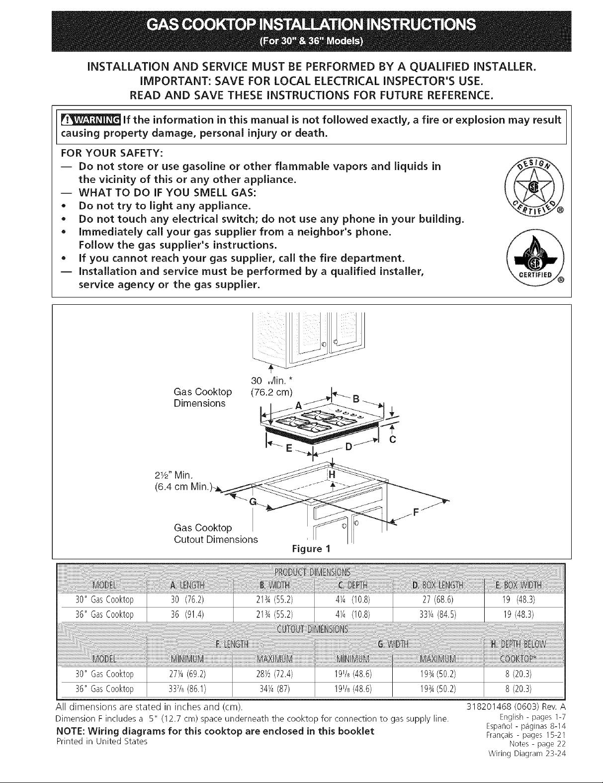
Gas Cooktop
Dimensions
21/2"Min.
(6.4 cm
Gas Cooktop
Cutout Dimensions
Figure 1
!!!!!!!!!!!!!!!!!!!!!!!!!!!!!_!_!_!_!_!_!_!_!_!Jii_ii_ii_ii_i!_ii!i_i_!ii!i_!i!ii_!_ii_ili_ii_i_iiiiiiii!!i!!i!!i!i!i!iii!ili!iiiiiiiiiiiiiiiiiiiilliiiiiiiiiiiiiiiiiiiiiilliiiiiiiliiii!i!i_i!ii!iliiiilililililill_i_!i_ii!ii!ii!ii!ii!i_!!!!!!i_!i_!!_!i_i!!i_!i!!i!!i!!i!i_iiii!ii!ii!i!i!ii!_!i_i!_!i!iiiiiiiiiii!i!!i!i!!i!!i!!i!!i!i_i!_i!ii!iliiii!i!iiiiiiiiiiiiiiiiiiiiiiiiii!iiii!i!i_i!_!i_iiii_i_i_i!!_!i!!!i!!!i_!i!!!';i!_i_i_iii!i_i__!i_!_!i_:!_i_i!_ili_ii!!ii_i!!_!ii_!ii!i_!iii_i!i_i_!ii!ii!i_iiiii_i_i!_i_!i_i__iii_i_i_i_iiiiiiii!iiii!i!i!i!i_ii!ii_i_!i!_i;!i_i__!!!_iiii!iiii_!ii_:i_!i_ii_ii_ii_i!i_i_iiii_i_ii!i!i_iii_!i_!i_!i_!i_iiiiii!ii_i_ii_i_i!i_!!_!i_!i_!ii_i_i_i_i_ililililiiiiiii!i_!i!!i!!i!ii!ii!i_!!!i!!i_!;!!_!i_i_i!_i_!ii_ili_ii_ii!i'ii_i!iiiiiiiiiii_ii_!_'_i_ii_ili!ii!ilii_i!i!i!ii!ii!ii!i!!i!ii!ii!ii!ii!ii!i_!ii!ii!ii!ii!_!_:i_i!_i!i!ii!ii!_i_ii_ii_ii:_iiiii_i!i!i_ii_ii_ii_ii_ii!i_!_!i:!i_ii_i_iii_i_i_!i_ii_ii!i!ii!i!ili!iili!!i!!i!!i!!i!_i_ii!ii!ii!ii!ili!iiii_i_i_i_i_i_i,!,!!
30"GasCooktop 30 (76.2) 21_A(55.2) 4_A(10.8) 27(68.6) 19 (48.3)
36"GasCooktop 36 (91.4) 213A(55.2) 4_A(10.8) 331/4(84.5) 19(48.3)
! ! M !M:
30" GasCooktop 271/4(69.2) 281/2(72.4) 191/s(48.6) 193A(50.2)
36" GasCooktop 337/s(86.1) 34_A(87) 191/_(48.6) 193A(50.2)
All dimensions are stated in inches and (cm).
Dimension F includes a 5" (12.7 cm) space underneath the cooktop for connection to gas supply line.
NOTE: Wiring diagrams for this cooktop are enclosed in this booklet
Printed in United States
318201468 (0603)Rev. A
8 (20.3)
8 (20.3)
English - pages 1-7
Espa_ol- paginas 8-14
Frangais - pages 15-21
Notes- page 22
Wiring Diagram 23-24
Important Notes to the Installer
I. Read all instructions contained in these installation
instructions before installing the cooktop.
2. Remove all packing material before connecting the
electrical supply to the cooktop.
3. Observe all governing codes and ordinances.
4. Be sure to leavethese instructions with the consumer.
5. Note: For operation at 2000 ft. elevations above see
level, appliance rating shall be reduced by 4 percent
for each additional 1000 ft.
Important Note to the Consumer
Keep these instructions with your Useand Care Guide for
future reference.
IMPORTANT SAFETY
INSTRUCTIONS
Installation of this cooktop must conform with local codes
or, in the absence of local codes, with the National Fuel
Gas Code ANSI Z223.1/NFPA 54 in the United States, or
in Canada, with the Canadian Fuel Gas Code, CAN/CGA
B149 and CAN/CGA B149.2.
When installed in a manufactured (mobile) home
installation must conform with the Manufactured Home
Construction and Safety Standard, title 24 CFR,part
3280 [Formerly the Federal Standard for Mobile Home
Construction and Safety, title 24, HUD (part 280)] or,
when such standard is not applicable, the Standard for
Manufactured Home Installation, ANSI/NCSBCS A225.1
or with local codes where applicable.
This cooktop has been design certified by CSA
International. As with any appliance using gas and
generating heat, there are certain safety precautions you
should follow. You will find them in the Useand Care
Guide, read it carefully.
• Be sure your cooktop is instaJJed and grounded
properly by a qualified installer or service
technician.
This cooktop must be electrically grounded in
accordance with local codes or, in their absence,
with the National ElectricaJ Code ANSI/NFPA No.
70--latest edition in the United States, or in
Canada, with the Canadian Electrical Code, CSA
C22.1 Part 1.
• The burners can be lit manually during an
electrical power outage. To light a burner, hold a
lit match to the burner head, then slowly turn the
Surface Control knob to MTE. Use caution when
lighting burners manually.
• Do not store items of interest to children in
cabinets above the cooktop. Children could be
seriously burned climbing on the cooktop to reach
items.
• To eliminate the need to reach over the surface
burners, cabinet storage space above the burners
should be avoided.
• Adjust surface burner flame size so it does not
extend beyond the edge of the cooking utensil
Excessive flame is hazardous.
• Never use your cooktop for warming or heating
the room. Prolonged use of the cooktop without
adequate ventilation can be hazardous.
• Do not store or use gasoline or other flammable
vapors and liquids near this or any other
appliance. Explosions or fires could result.
The electrical power to the cooktop
must be shut off while gas line connections are
being made. FaiJure to do so could resuJt in serious
injury or death.
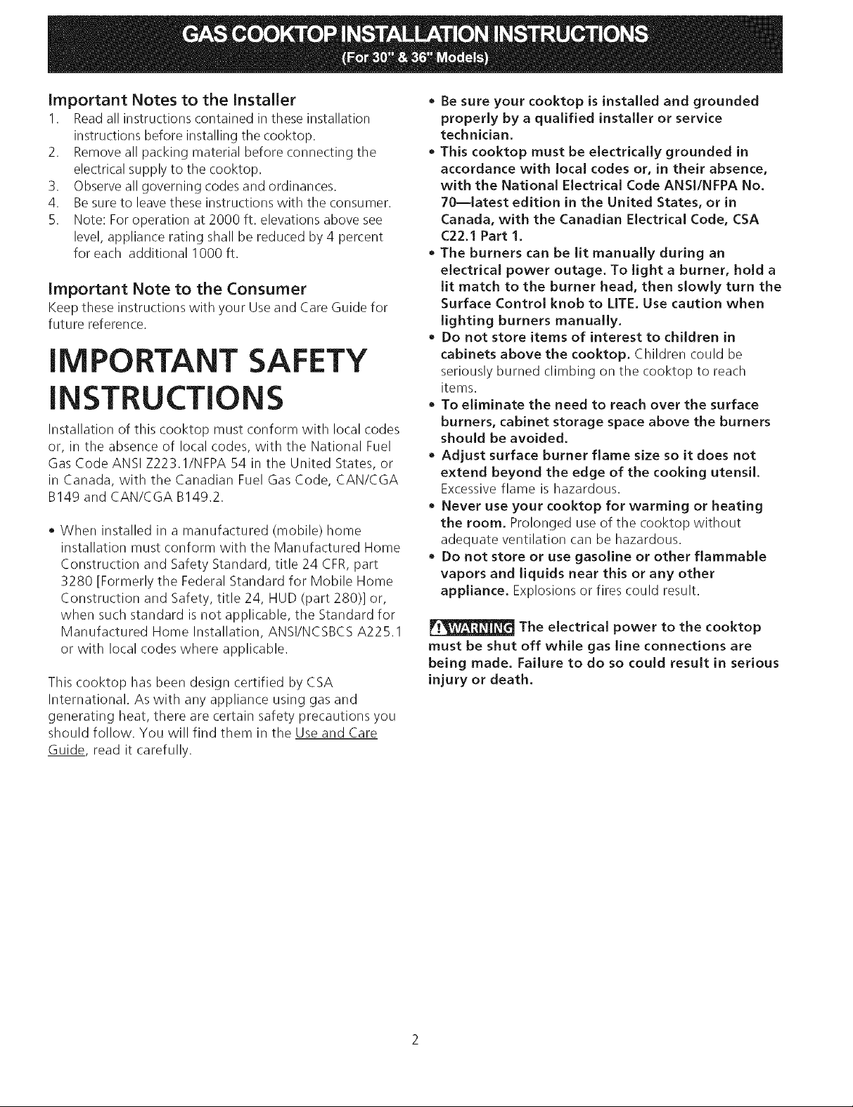
13" (33 cm)
Max. Depth
For Cabinet
Installed Above
Cooktop.
B
18" Min,
(45.7 cm)
k
I
11/2"(3.8 cm)Minimum Distance
Between RearEdge of Cutout
and Nearest Combustible Surface
Above Countertop,
Clearance
30" (76.2 cm)
Min, Clearance
Between the
Top of the
Cooking
Platform and
Unprotected
Wood or Metal
Cabinet
24" cm)
\
_To eliminate the risk of
burns or fire from reaching over heated
surfaces, cabinet storage space located
above the cooktop should be avoided. If
cabinet storage is provided, risk can be
reduced by installing a range hood that
projects horizontally a minimum of 5"
(12.7 cm) beyond the bottom of the
cabinets.
Drawers Cannot Be Used with This
Cooktop Since Burner Box Extends
3s/32'' (8.02 cm) Below Surface of
Countertop.
30'_Cooktop 30'_(76.2 cm) 7'_(17.8 cm)
36'_Cooktop 36'_(91.4 cm) 7'_(17.8 cm)
Figure 2 - CABINET DESIGN
7"(17.8 cm)
7"(17.8 cm)
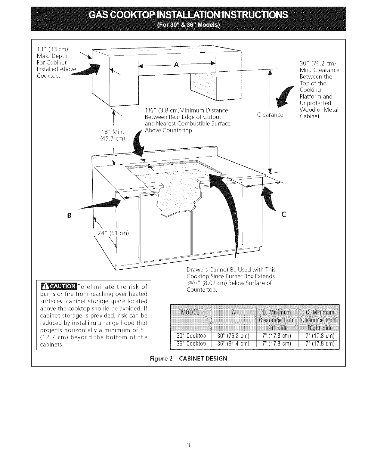
Wall Outlet Location
12"_
To clamp down, insert an angle bracket into the slot on
each side of the unit as shown.Run thumb screw up
through the bracket, up against the bottom of the
counter. Tighten until the unit draws down and issecure.
Provide an Adequate Gas Supply
This cooktop is designed to operate on natural gas at 4"
of manifold pressure only.
10"
A pressure regulator is connected in series with the
manifold on the cooktop and must remain in series with
the supply line.
Recommended area for
12OV grounded outlet
on rear wall.
_.._F U_N_T 22"
: NOTE: If an outlet
I is not available,
have one installed by
i a qualified technician. _,
OF UNIT
Figure 3
Cooktop Installation
1. Visually inspect the cooktop for damage.
2. Set the cooktop into the countertop cutout.
NOTE: Do not use caulking compound; cooktop should
be removable for service when needed.
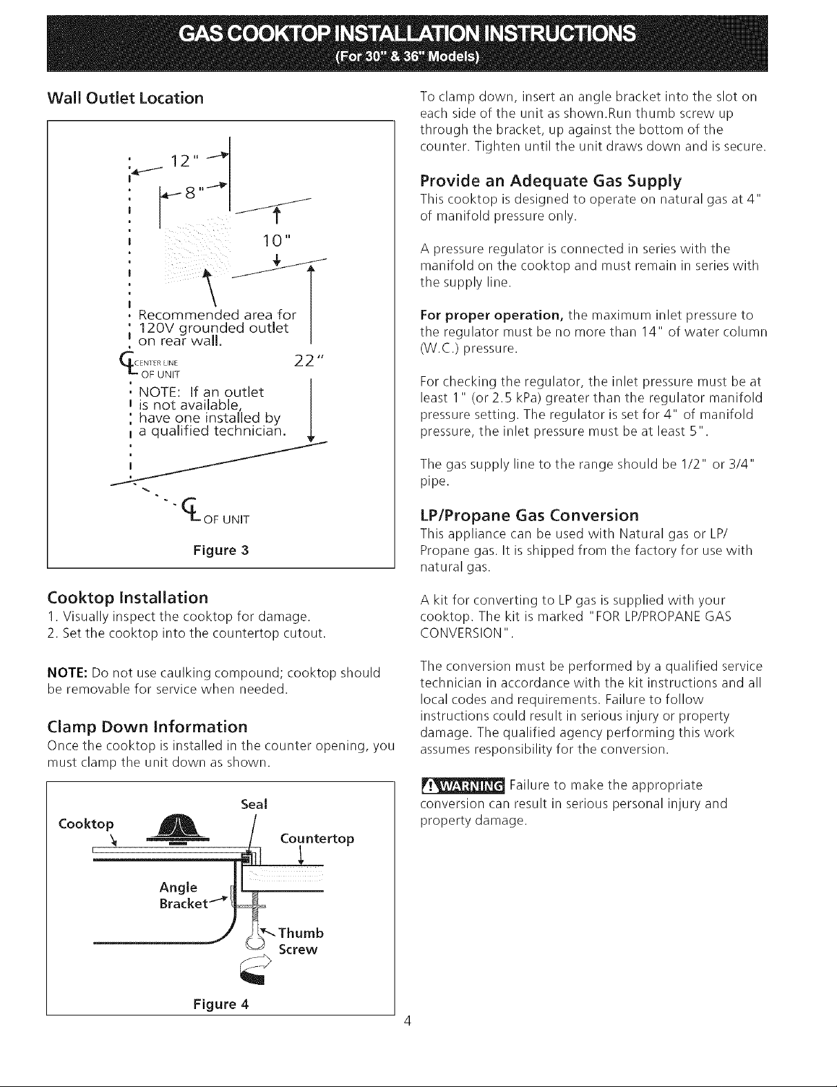
Clamp Down Information
Once the cooktop is installed in the counter opening, you
must clamp the unit down as shown.
Seal
Cooktop A /
For proper operation, the maximum inlet pressure to
the regulator must be no more than 14" of water column
(W.C.) pressure.
For checking the regulator, the inlet pressure must be at
least 1" (or 2.5 kPa) greater than the regulator manifold
pressure setting. The regulator is set for 4" of manifold
pressure, the inlet pressure must be at least 5".
The gas supply line to the range should be I/2" or 3/4"
pipe.
LP/Propane Gas Conversion
This appliance can be used with Natural gas or LP/
Propane gas. It is shipped from the factory for use with
natural gas.
A kit for converting to LPgas is supplied with your
cooktop. The kit is marked "FOR LP/PROPANEGAS
CONVERSION".
The conversion must be performed by a qualified service
technician in accordance with the kit instructions and all
local codes and requirements. Failure to follow
instructions could result in serious injury or property
damage. The qualified agency performing this work
assumes responsibility for the conversion.
Failure to make the appropriate
conversion can result in serious personal injury and
property damage.
Angle IL
Bracket_"/#_
Figure 4
4
Important: Removeallpackingmaterialand
literaturefromcooktopbeforeconnectinggasand
electricalsupplytocooktop.
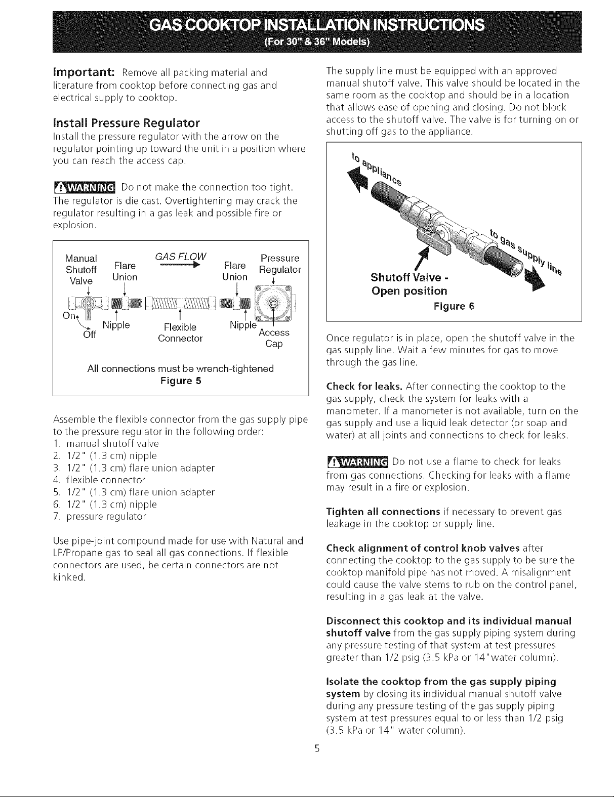
Install Pressure Regulator
Install the pressure regulator with the arrow on the
regulator pointing up toward the unit in a position where
you can reach the access cap.
Do not make the connection too tight.
The regulator is die cast. Overtightening may crack the
regulator resulting in agas leak and possible fire or
explosion.
Manual GAS FLOW Pressure
Shutoff Flare _'_ Flare Regulator
Valve Union Union _,
÷
Nipple Flexible Access
Off Connector
All connections must be wrench-tightened
Figure 5
Assemble the flexible connector from the gas supply pipe
to the pressure regulator in the following order:
I. manual shutoff valve
2. I/2" (1.3 cm) nipple
3. 1/2" (1.3 cm) flare union adapter
4. flexible connector
5. I/2" (1.3 cm) flare union adapter
6. 1/2" (1.3 cm) nipple
7. pressure regulator
Use pipe-joint compound made for use with Natural and
LP/Propane gas to seal all gas connections. If flexible
connectors are used, be certain connectors are not
kinked.
Cap
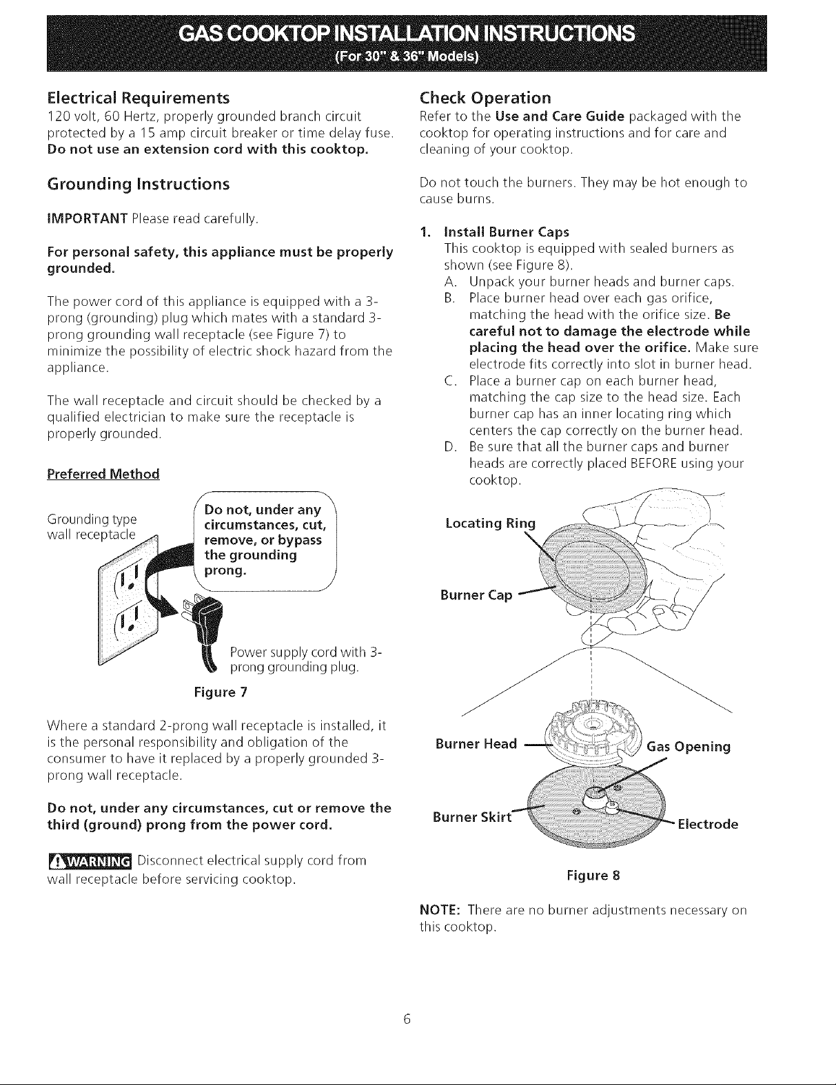
The supply line must be equipped with an approved
manual shutoff valve. This valve should be located in the
same room as the cooktop and should be in a location
that allows ease of opening and closing. Do not block
access to the shutoff valve. The valve is for turning on or
shutting off gas to the appliance.
Shutoff Valve =
Open position
Figure 6
Once regulator is in place, open the shutoff valve in the
gas supply line. Wait a few minutes for gas to move
through the gas line.
Check for leaks. After connecting the cooktop to the
gas supply, check the system for leaks with a
manometer. If a manometer is not available, turn on the
gas supply and use a liquid leak detector (or soap and
water) at all joints and connections to check for leaks.
Do not use a flame to check for leaks
from gas connections. Checking for leaks with a flame
may result in a fire or explosion.
Tighten all connections if necessary to prevent gas
leakage in the cooktop or supply line.
Check alignment of control knob valves after
connecting the cooktop to the gas supply to be sure the
cooktop manifold pipe has not moved. A misalignment
could cause the valve stems to rub on the control panel,
resulting in a gas leak at the valve.
Disconnect this cooktop and its individual manual
shutoff valve from the gas supply piping system during
any pressure testing of that system at test pressures
greater than I/2 psig (3.5 kPa or 14"water column).
Isolate the cooktop from the gas supply piping
system by closing its individual manual shutoff valve
during any pressure testing of the gas supply piping
system at test pressures equal to or lessthan I/2 psig
(3.5 kPa or 14" water column).
EJectdcal Requirements
120 volt, 60 Hertz, properly grounded branch circuit
protected by a 15 amp circuit breaker or time delay fuse.
Do not use an extension cord with this cooktop.
Check Operation
Refer to the Use and Care Guide packaged with the
cooktop for operating instructions and for care and
cleaning of your cooktop.
Grounding Instructions
iMPORTANT Please read carefully.
For personal safety, this appliance must be properly
grounded.
The power cord of this appliance isequipped with a 3-
prong (grounding) plug which mates with a standard 3-
prong grounding wall receptacle (see Figure 7) to
minimize the possibility of electric shock hazard from the
appliance.
The wall receptacle and circuit should be checked by a
qualified electrician to make sure the receptacle is
properly grounded.
Preferred Method
Grounding type
wall receptacle
not, under any_'_
circumstances, cut, I
remove, or bypass I
the grounding )
_rong. J
Do not touch the burners. They may be hot enough to
cause burns.
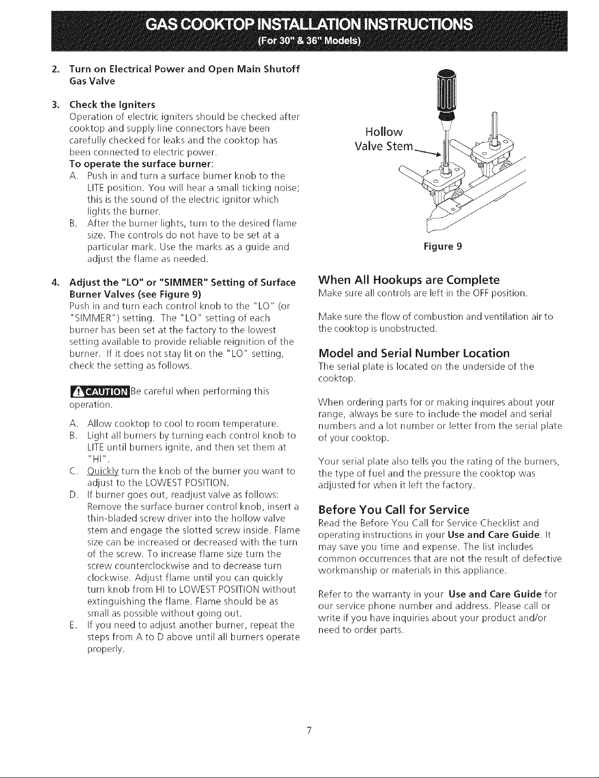
.
Install Burner Caps
This cooktop is equipped with sealed burners as
shown (see Figure 8).
A. Unpack your burner heads and burner caps.
B. Place burner head over each gas orifice,
matching the head with the orifice size. Be
careful not to damage the electrode while
pJacing the head over the orifice. Make sure
electrode fits correctly into slot in burner head.
C. Place a burner cap on each burner head,
matching the cap size to the head size. Each
burner cap has an inner locating ring which
centers the cap correctly on the burner head.
D. Be sure that all the burner caps and burner
heads are correctly placed BEFOREusing your
cooktop.
Power supply cord with 3-
prong grounding plug.
Figure 7
Where a standard 2-prong wall receptacle is installed, it
is the personal responsibility and obligation of the
consumer to have it replaced by a properly grounded 3-
prong wall receptacle.
Do not, under any circumstances, cut or remove the
third (ground) prong from the power cord.
Disconnect electrical supply cord from
wall receptacle before servicing cooktop.
Burner Head
Gas Opening
Figure 8
NOTE: There are no burner adjustments necessary on
this cooktop.
2. Turn on Electrical Power and Open Main Shutoff
Gas Valve
,
Check the igniters
Operation of electric igniters should be checked after
cooktop and supply line connectors have been
carefully checked for leaks and the cooktop has
been connected to electric power.
To operate the surface burner:
A. Push in and turn a surface burner knob to the
LITE position. You will hear a small ticking noise;
this isthe sound of the electric ignitor which
lights the burner.
B. After the burner lights, turn to the desired flame
size. The controls do not have to be set at a
particular mark. Use the marks as a guide and
adjust the flame as needed.
/
J
Figure 9
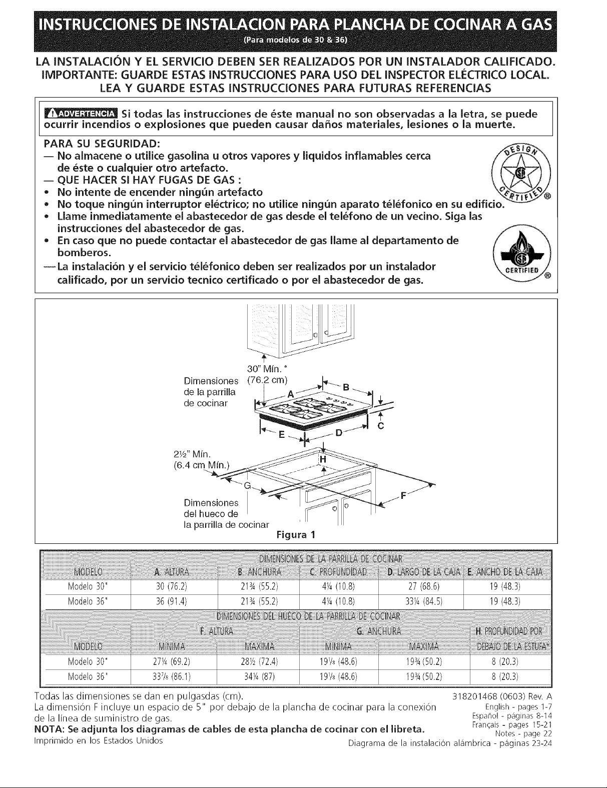
,
Adjust the "LO" or "SIMMER" Setting of Surface
Burner Valves (see Figure 9)
Push in and turn each control knob to the "LO" (or
"SIMMER") setting. The"LO" setting of each
burner has been set at the factory to the lowest
setting available to provide reliable reignition of the
burner. If it does not stay lit on the"LO" setting,
check the setting as follows.
_Be careful when performing this
operation.
A. Allow cooktop to cool to room temperature.
B. Light all burners by turning each control knob to
LITEuntil burners ignite, and then set them at
"HI".
C. _turn the knob of the burner you want to
adjust to the LOWEST POSITION.
D. If burner goes out, readjust valve asfollows:
Remove the surface burner control knob, insert a
thin-bladed screw driver into the hollow valve
stem and engage the slotted screw inside. Flame
size can be increased or decreased with the turn
of the screw. To increase flame size turn the
screw counterclockwise and to decrease turn
clockwise. Adjust flame until you can quickly
turn knob from HI to LOWESTPOSITIONwithout
extinguishing the flame. Flame should be as
small as possible without going out.
E. If you need to adjust another burner, repeat the
steps from A to D above until all burners operate
properly.
When All Hookups are Complete
Make sure all controls are left in the OFFposition.
Make sure the flow of combustion and ventilation air to
the cooktop is unobstructed.
Model and Serial Number Location
The serial plate is located on the underside of the
cooktop.
When ordering parts for or making inquires about your
range, always be sure to include the model and serial
numbers and a lot number or letter from the serial plate
of your cooktop.
Your serial plate also tells you the rating of the burners,
the type of fuel and the pressure the cooktop was
adjusted for when it left the factory.
Before You Call for Service
Read the Before You Call for Service Checklist and
operating instructions in your Use and Care Guide. It
may save you time and expense. The list includes
common occurrences that are not the result of defective
workmanship or materials in this appliance.
Refer to the warranty in your Use and Care Guide for
our service phone number and address. Please call or
write if you have inquiries about your product and/or
need to order parts.
LA INSTALACION Y EL SERVICIO DEBEN SER REAUZADOS POR UN INSTALADOR CALiFICADO.
IMPORTANTE: GUARDE ESTAS INSTRUCCIONES PARA USO DEL iNSPECTOR ELECTRICO LOCAL.
LEA Y GUARDE ESTAS INSTRUCCIONES PARA FUTURAS REFERENCIAS
Si todas las instrucciones de _ste manual no son observadas a la letra, se puede
ocurrir incendios o explosiones que pueden causar da5os materiales, lesiones o la muerte.
PARA SU SEGURIDAD: _-,_
-- No almacene o utilice gasolina u otros vapores y liquidos inflamables cerca
de _ste o cualquier otro artefacto.
QUE HACER SI HAY FUGAS DE GAS :
No intente de encender ningun artefacto ®
No toque ningun interruptor el_ctrico; no utilice ningun aparato t_l_fonico en su edifi
• Llame inmediatamente el abastecedor de gas desde el tel_fono de un vecino. Siga las
instrucciones del abastecedor de gas.
• En caso que no puede contactar el abastecedor de gas Ilame al departamento de
bomberos.
--La instalaci6n y el servicio t_l_fonico deben ser realizados por un instalador
calificado, por un servicio tecnico certificado o por el abastecedor de gas.
Dimensiones
de la parrilla
de cocinar
Dimensiones
del hueco de
la parrilla de cocinar
Figura 1
Modelo30" 30(76.2) 213A(55.2) 4V_(10.8) 27(68.6) 19(48.3)
Modelo36" 36(91.4) 213A(55.2) 4V_(10.8) 33_A(84.5) 19(48.3)
Modelo30" 27V4(69.2) 28V2(72.4) 19V8(48.6) 193A(50.2) 8(20.3)
Modelo36" 337/8(86.1) 34V4(87) 19V8(48.6) 193A(50.2) 8 (20.3)
Todas las dimensiones se dan en pulgasdas (cm). 318201468 (0603) Rev.A
La dimension F incluye un espacio de 5" pot debajo de la plancha de cocinar para la conexiOn English- pages1-7
de la linea de suministro de gas. Espaf_ol- paginas8-14
NOTA: Se adjunta los diagramas de cables de esta pJancha de cocinar con el Jibreta. Francais- pages 15-21
Imprimido en los Estados Unidos Diagrama de la instalaci6n aDmbrica - p_qginas23-24
Notes- page 22
 Loading...