

Page 1
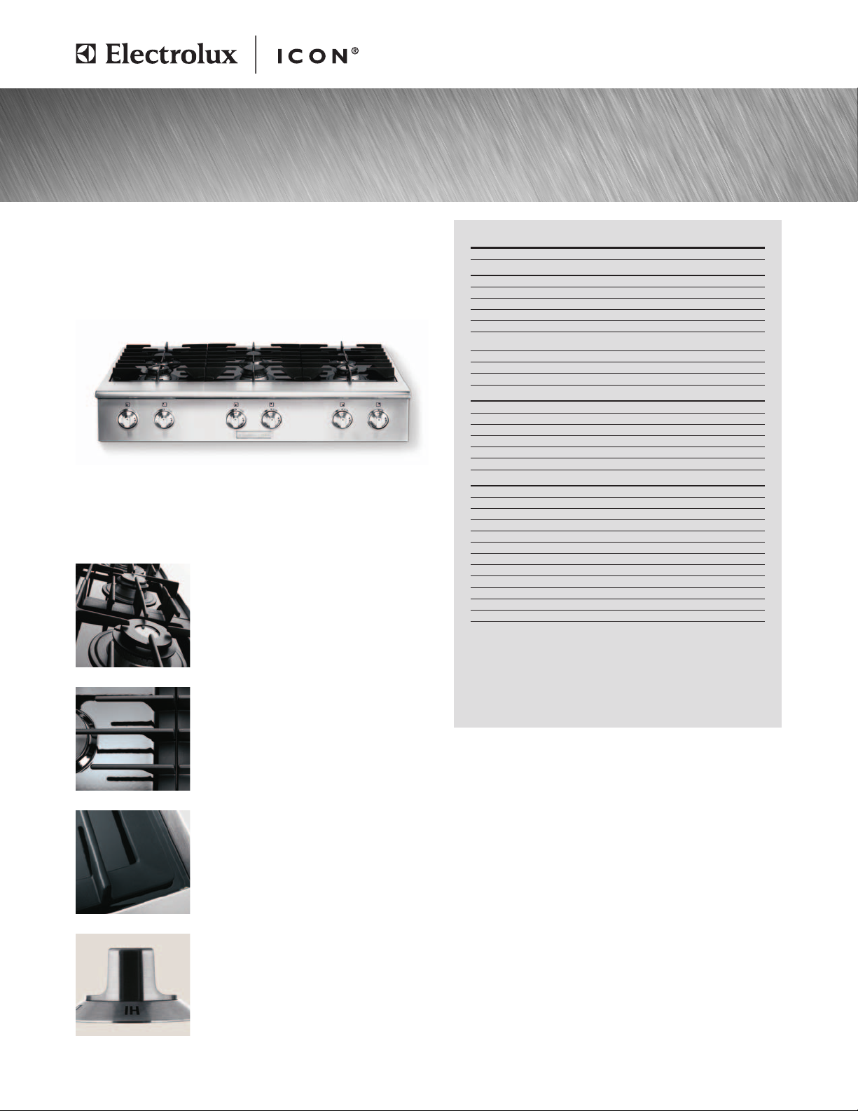
36" GAS SLIDE-IN COOKTOP
Configuration
FEATURES
Formed Stainless Steel Platform
Large Professional Skirted Knobs with Bezel
Min-2-Max™Dual-Ring Sealed Burner (BTU)
Sealed Power Burner™(BTU)
Sealed Burner (BTU)
Sealed Precision Burner
™
(BTU)
Linear Flow Burner Valves
Electronic Ignition with Auto Re-Ignition
Continuous Grates
ACCESSORIES
Griddle
Wok Ring
Simmer Plate
9" Stainless Steel Backsplash – PN# 903048-9010
Black Knobs Kit – PN# 903049-9120
Depth Adjustment Filler Kit* – PN # 903051-9010
SPECIFICATIONS
Overall Exterior Dimensions –
Height
Width
Depth
Gas Inlet/ Power Supply Location
LP Gas Conversion Kit
Voltage Rating
Connected Load (kW Rating) @120 Volts
‡
Electrical Cable
Approved for Single Oven Combination Installation**
Approved for Downdraft Vent Combination Installation**
Shipping Weight (Approx.)
* When replacing an existing cooktop with countertop cutout deeper than 7-1/4"
and less than 8-1/2", order free Depth Adjustment Filler Kit.
‡ For use on adequately wired 120V, dedicated circuit having 2-wire service with
a separate ground wire. Appliance must be grounded for safe operation.
** Not approved to be used over any Electrolux ICON®Single Wall Oven. Approved to be
used in combination with an Electrolux ICON®Downdraft Vent. (Proper combination
installation will require cooktop power cord to be relocated.)
NOTE: Always consult local and/ or national electric and gas codes. Refer to Product
Installation Guide for detailed installation instructions on the web at electroluxicon.com.
Specifications subject to change.
6 Sealed Burners
Yes
6
2 (18,000 – 450)
1 (14,000)
1 (13,000)
1 (9,500)
1 (5,000)
6
Yes
3
Included
Included
Included
Optional
Optional
Optional
7-3/4"
35-7/8"
25"
Right Rear
Included
120V/ 60Hz /15A
0.001
Included
No
Yes
120 Lbs.
electroluxicon.com
Min-2-Max™Burners
Burner configuration includes two versatile
Min-2-Max
™
sealed burners delivering anywhere
from 18,000 to 450 BTUs. Thanks to the double
ring configuration, you can simmer sauces or
bring water to a boil. You decide the level of heat
output by a simple turn of the knob.
Six Sealed Burners
Versatile sealed burner configuration provides
the utmost in cooking flexibility. Includes:
two 18,000 - 450 BTU Min-2-Max
™
burners,
one 14,000 BTU Power Burner
™
, one 13,000
BTU Burner, one 9,500 BTU Precision Burner
™
and one 5,000 BTU Precision Burner™.
Sealed Cooktop Spill-Basin
Cleanup is convenient with a black porcelaincoated area beneath the burners to catch spills.
Professional-Style Controls
Large professional-feel, front-mounted control
knobs provide easy and accurate settings. 270
degree rotation offers superior flame control.
Optional black knobs available.
Designed for the well-lived home.
Gas Slide-In Cooktop
E36GC76GPS
Page 2
Gas Slide-In Cooktop
E36GC76GPS
High standards of quality at Electrolux Home Products, Inc. mean we are
constantly working to improve our products. We reserve the right to change
specifications or discontinue models without notice.
Electrolux Major Appliances, N.A.
USA
•
250 Bobby Jones Expressway •Augusta, GA 30907 •1-877-4electrolux (1-877-435-3287)
•
electroluxicon.com
CANADA
•
5855 Terry Fox Way •Mississauga, ON L5V 3E4 •1-800-265-8352
•
electroluxicon.ca
E36GC76GPS 01/09 © 2009 Electrolux Home Products, Inc. Printed in the U.S.A.
36" Gas Slide-In Cooktop Specifications
•
Product Weight – 115 Lbs.
•
Voltage Rating –120V / 60Hz / 15 Amp
•
Connected Load (kW Rating) @120 Volts = 0.001kW (For use on
adequately wired 120V, dedicated circuit having 2-wire service with a
separate ground wire. Appliance must be grounded for safe operation.)
•
Amps @120 Volts = 0.008 Amps
•
Always consult local and/or national electric and gas codes.
•
Cooktop ships with 3/4" factory regulator.
•
LP Gas conversion kit supplied.
•
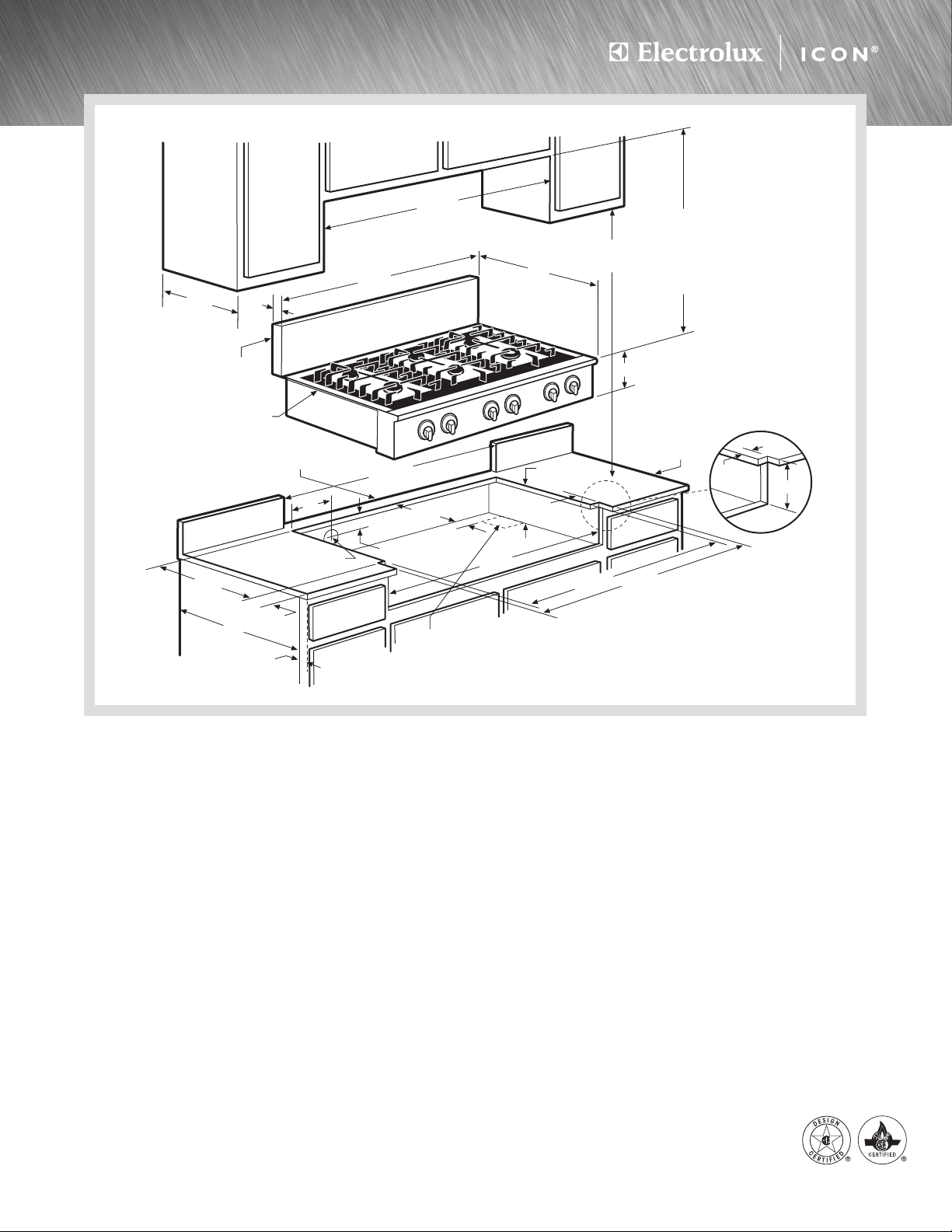
Plan installation to have electrical connection, gas shutoff valve, and
pressure regulator accessible from front of cabinet. Locate 120V
grounded outlet in a 4"W x 5"H area on rear wall, 16" above floor,
aligned center with cooktop.
•
Cabinet and/or countertop must completely enclose recessed portion
of cooktop. Respect cutout dimensions and clearances and ensure
that all contact surfaces are solid and level.
•
Overhead cabinetry should not exceed a 13" maximum depth.
•
Allow 30" minimum clearance between top of cooktop and bottom of
unprotected wood or metal overhead cabinetry.
•
Absolute minimum horizontal distance between overhead cabinets
installed to either side of appliance must be no less than maximum width
of appliance.
•
Allow 24" minimum clearance when bottom of wood or metal overhead
cabinet is protected by not less than 1/8" flame-retardant millboard
covered with not less than No.28 MGS sheet steel, 0.015" stainless
steel, 0.024" aluminum or 0.020" copper.
•
Allow 1" minimum clearance between rear edge of cooktop and nearest
combustible surface above countertop. If required clearance can not be
maintained, then optional stainless steel backsplash or noncombustible
backsplash material must be used – otherwise installation will require
custom cabinet and countertop dimensions.
•
Allow 7" minimum clearance from edge of cooktop to nearest
combustible wall on either side of unit.
•
It is recommended that drawers not be used beneath cooktop.
•
To reduce risk of fire when using overhead cabinetry, install vent hood
that projects horizontally a recommended minimum of 7" beyond bottom
of cabinets.
•
Gas Slide-In Cooktop model E36GC76GPS is NOT approved to be used
over any Electrolux ICON® Single Wall Oven.
•
Gas Slide-In Cooktop model E36GC76GPS (without optional backsplash)
is approved to be used in combination with an Electrolux ICON
®
36” Downdraft Vent. (Refer to Slide-In Cooktop/Downdraft Vent
Countertop Preparation page on web for detailed installation
specifications.) Proper combination installation will require cooktop power
cord to be relocated to underside of unit. (For details, refer to 30" & 36"
Gas Slide-In Cooktop Power Cord Relocation Instructions on web.)
Note: For planning purposes only. Refer to Product Installation Guide
on the web at electroluxicon.com for detailed instructions.
Optional Accessories
•
When replacing an existing cooktop with countertop cutout deeper
than 7-1/4" and less than 8-1/2", order free Depth Adjustment Filler Kit –
(PN# 903051-9010).
•
9" Stainless Steel Backsplash – (PN# 903048-9010).
•
Black Knobs Kit – (PN# 903049-9120).
25"
35 7/8"
2"
36" min.
13"
max.
cabinet
depth
18"
min.
30" min. for
unprotected cabinet
24" min. with
protected bottom
surface
**Applies only in case
of countertop backwall
73/4"
Side inset 5/8"
Optional 9" stainless
steel backsplash
(attaches to wall)
3515/16"**
11/8"
max.
Support
platform
71/2"
35
3
/16"*
35
15
/16"*
1" countertop
overhang
*Both cutout dimensions are
critical to proper cooktop installation.
Due to variations in countertop materials it
is recommended to undercut finished dimension
35
15
/16" and adjust upon installation of cooktop.
7
1
/4"
3
/8"
24"
1" min. recommended distance between
rear edge of cutout and nearest combustible
surface above countertop
2"
3"
2" dia.
opening to route
power cable
21/2"
7" min. to nearest
combustible wall
(either side of unit)
4" x 4" opening to
route gas supply
221/8"
35
1
/8"
Page 3
Slide-In Cooktop/Downdraft Vent
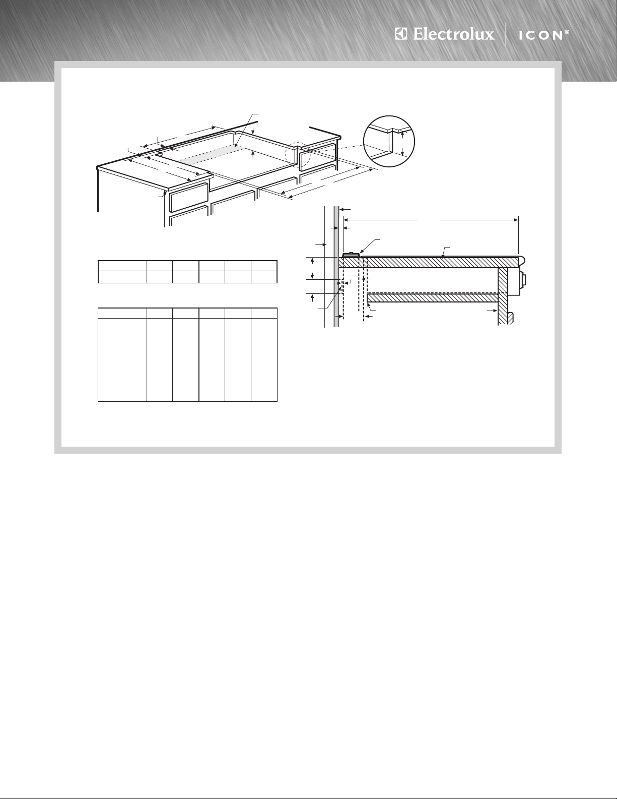
Countertop Preparation Specifications
•
For detailed Slide-In Cooktop installation, refer to model-specific product
page and installation guide on web. Plan installation so that all required
minimum clearances between cooktop, overhead cabinets and adjacent
vertical walls are provided.
•
Position cooktop/vent cutout so all required minimum clearances are met.
•
Minimum flat countertop area must meet or exceed combined overall
width and depth as shown. Standard 25" countertop depth is NOT
adequate for slide-in cooktop/vent installations.
•
Separate circuits required for cooktop and vent. (Refer to product-specific
electrical specifications.)
•
Always consult local and/or national electric and gas codes. Check local
building codes for installation requirements, as they may vary per locale.
•
Proper combination installation will require 30" & 36" Gas Slide-In
Cooktop power cord to be relocated to underside of unit. (For details,
refer to 30" & 36" Gas Slide-In Cooktop Power Cord Relocation
Instructions on web.)
Downdraft Vent Specifications
•
For detailed Downdraft Vent installations, refer to model-specific
product page and installation guide on web.
•
Voltage Rating –120V / 60Hz / 15 Amps
•
Connected Load (kW Rating) @120 Volts = 1.0kW
(For use on adequately wired 120V, dedicated circuit having 2-wire
service with a separate ground wire. Appliance must be grounded for
safe operation.)
•
Amps @120 Volts = 8.0 Amps
•
Vent unit outside of building only.
•
Vent must be installed in vertical orientation only.
•
1,600 CFM remote exhaust blower (PN# 5304444802) included with
vent – shipped in separate box.
•
Do not use flexible duct. Round duct instead of rectangular duct
recommended, especially when elbows are required.
•
When multiple elbows are necessary, ensure a minimum of 24" of straight
duct between any two elbows.
•
Thermal breaks such as short section of nonmetallic duct, should be
used in areas of extreme cold.
•
For most efficient airflow exhaust, use a straight run or as few elbows
as possible.
•
Cold weather installations should have additional backdraft damper
installed.
•
Installing a Downdraft Vent in combination with any gas cooking surface
will affect optimum burner efficiency.
•
Downdraft Vents can NOT be used in combination with any cooktop
backsplash.
Note: For planning purposes only. Refer to Product Installation Guide
on the web at electroluxicon.com for detailed instructions.
High standards of quality at Electrolux Home Products, Inc. mean we are
constantly working to improve our products. We reserve the right to change
specifications or discontinue models without notice.
Electrolux Major Appliances, N.A.
USA
•
250 Bobby Jones Expressway •Augusta, GA 30907 •1-877-4electrolux (1-877-435-3287)
•
electroluxicon.com
CANADA
•
5855 Terry Fox Way •Mississauga, ON L5V 3E4 •1-800-265-8352
•
electroluxicon.ca
SIC_DDV_PREP 01/09 © 2009 Electrolux Home Products, Inc. Printed in the U.S.A.
Countertop Preparation for 30" & 36" Slide-In Cooktop/Downdraft Vent Installation
Cooktop Installation Note:
To ensure proper installation, refer to model-specific installation
guide on web for cooktop dimensions, cutout dimensions and
cabinet requirements.
Countertop Preparation Note:
Countertop with backsplash may not allow enough flat area for
proper installation, 2-13/16" of flat countertop required behind
cooktop. No gap required between back of cooktop and front
of downdraft trim piece.
*Standard 25" countertop depth is NOT adequate for slide-in
cooktop/vent installations.
Stiffener
Back side of
cabinet front
Vent unit
Downdraft
chimney top
Slide-In Cooktop
25
13
/16"
End of cooktop
support platform
Countertop*
213/16"
3"
Vertical noncombustible surface - rear wall
Studwall
1
/4"min. flat ledge
115/16"
9
/32"
E36DD75ESS/36" Cooktop Cutout Dimensions
36" Cooktops A B C D E
E36EC75DSS 35
15
/16" 35 3/16" 22" 25 13/16" 33 3/4"
E36EC75ESS 35
15
/16" 35 3/16" 22" 25 13/16" 33 3/4"
E36EC75HSS 35
15
/16" 35 3/16" 22" 25 13/16" 33 3/4"
E36GC75DSS* 35
15
/16" 35 3/16" 22" 25 13/16" 33 3/4"
E36GC75ESS* 35 15/16" 35 3/16" 22" 25 13/16" 33 3/4"
E36GC75GSS* 35 15/16" 35 3/16" 22" 25 13/16" 33 3/4"
E36GC76EPS* 35
15
/16" 35 3/16" 22" 25 13/16" 33 3/4"
E36GC76GPS* 35 15/16" 35 3/16" 22" 25 13/16" 33 3/4"
E30DD75ESS/30" Cooktop Cutout Dimensions
30" Cooktop A B C D E
E30GC74GPS*
29 15/16"29 3/16" 22" 25 13/16" 27 3/4"
*Proper combination installation will require cooktop power cord
to be relocated to underside of unit.
(For details, refer to 30" & 36"
Gas Slide-In Cooktop Power Cord Relocation Instructions page.)
For detailed cooktop and
downdraft vent installation
specifications, refer to
model-specific product
page and installation
guide on web
7
1
/4"
1
/4" min.
flat ledge
Downdraft vent cutout opening
in cooktop support platform
B
A
1"countertop
overhang
C
2
9
/16"
7
1
/2"
E
D
Slide-In Cooktop/Downdraft Vent
Countertop Preparation
Page 4
30" & 36" Gas Slide-In Cooktop
Power Cord Relocation Instructions
High standards of quality at Electrolux Home Products, Inc. mean we are
constantly working to improve our products. We reserve the right to change
specifications or discontinue models without notice.
Electrolux Major Appliances, N.A.
USA
•
250 Bobby Jones Expressway •Augusta, GA 30907 •1-877-4electrolux (1-877-435-3287)
•
electroluxicon.com
CANADA
•
5855 Terry Fox Way •Mississauga, ON L5V 3E4 •1-800-265-8352
•
electroluxicon.ca
GC_PCRELO 08/08 © 2008 Electrolux Home Products, Inc. Printed in the U.S.A.
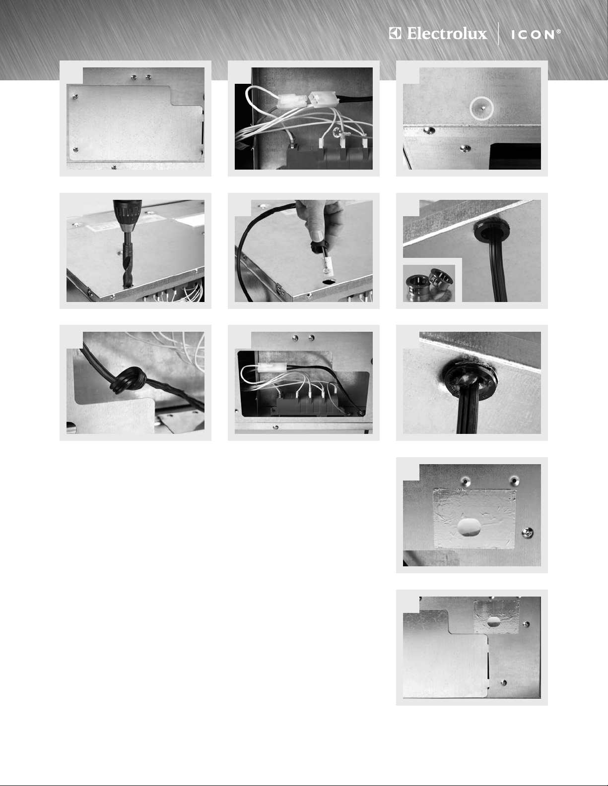
To install an Electrolux ICON®Gas Slide-In Cooktop in combination with an
Electrolux ICON®Downdraft Vent, cooktop power cord MUST be relocated to underside of unit.
Gas Slide-In Cooktops requiring this procedure are: E30GC74GPS, E36GC75DSS, E36GC75ESS,
E36GC75GSS, E36GC76EPS and E36GC76GPS.
Please have qualified electrician perform following rewiring procedure in accordance with local and
national electric codes.
Tools & Materials:
Phillips-Head Screwdriver, Hammer, Awl or Punch, Drill with 3/4" drill bit,
2-Plastic Inserts (73209-2470), Silicone Caulk and Aluminum Tape.
1 2 3
4 65
7 8 9
10
11
Procedure:
1. Remove electrical access panel from rear
of cooktop.
2. Disconnect power cord and ground wires,
then remove from cooktop.
3. Locate area for new hole to be drilled, 1/2"
in from back edge on underside of cooktop,
then mark hole location using an awl or punch.
4. Use 3/4" drill bit to drill new hole completely
through.
5. Route power cord wires through hole.
6. Place plastic inserts in upper and lower
drilled holes to protect cord.
7. Knot power cord to secure into place.
8. Reconnect power cord and ground wires.
9. Fill remaining hole surrounding power cord
with silicone caulk.
10. Cover both sides of original hole with two
layers of aluminum tape.
11. Screw electrical access panel back in place.
 Loading...