

Page 1
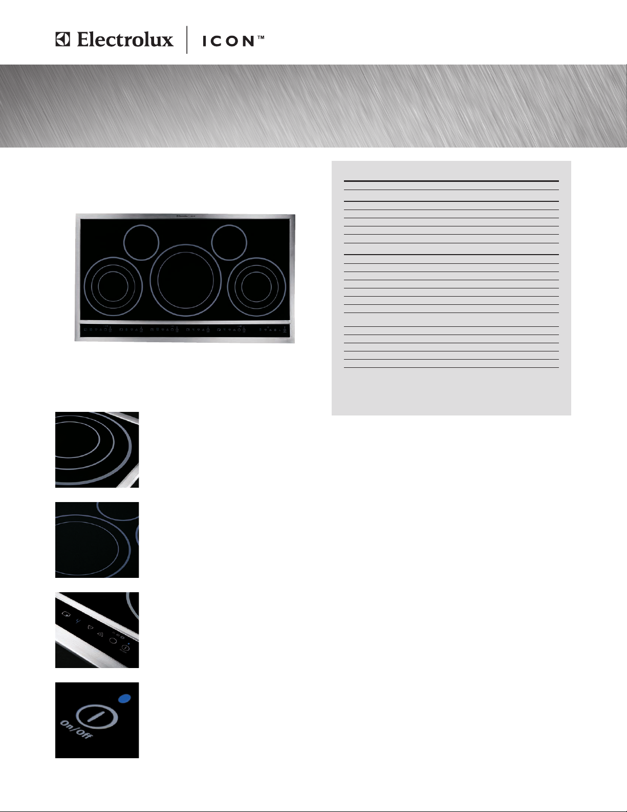
Designed for the well-lived home.
Electric Touch-Control Drop-In Cooktop
E36EC70FSS
36" ELECTRIC TOUCH-CONTROL DROP-IN COOKTOP
Configuration
FEATURES
Black Ceramic Smoothtop Glass Surface
6" Element – 1200W
5" to 7" to 9" Element – 1000W/ 1800W/2700W
9" to 12" Dual Element – 1700W/ 2700W
Custom-Set™Electronic Controls
SPECIFICATIONS
Overall Exterior Dimensions –
Height
Width
Depth
Power Supply Location
Amps@ 240/208 Volts
Connected Load (kW Rating) @ 240/ 208 Volts
Electrical – Single phase 3- or 4-wire cable, 120/ 240V or
120/ 208V, 60Hz, fused on both sides of line with ground.
Armored Electrical Cable
Approved for Single Oven Combination Installation*
Approved for Downdraft Vent Combination Installation*
Product Weight
Shipping Weight (Approx.)
*Approved to be used over any Electrolux ICON™Single Wall Oven and in combination
with an Electrolux ICON™Downdraft Vent.
NOTE: Always consult local and/ or national electric codes. Refer to Product Installation
Guide for detailed installation instructions on the web at electroluxicon.com.
Specifications subject to change.
5 Electric Elements
Yes
2
2
1
Yes
5"
36-3/4"
21-1/2"
Middle
44.0/ 38.0
10.5/ 7.9
Required
Included
Yes
Yes
50 Lbs.
56 Lbs.
5 Element Configuration
One 9"/12" double element (1700W/2700W),
two 5"/7"/9" triple elements (1000W / 1800W /
2700W) and two 6" elements (1200W) are
arranged to provide five concentric rings of
incomparable choices.
Ceramic Smoothtop Glass
Glass cooktop is flat, smooth and easy to clean
and maintain.
Custom-Set™Touch-Controls
The smooth cooktop surface is undisturbed
with knobs for a look that is sleek and flush with
your countertop.
Hot Surface Indicator
For added safety, when an element is still hot, a
blue LED indicator will stay on until surface cools.
electroluxicon.com
Page 2
Electric Touch-Control Drop-In Cooktop
E36EC70FSS
36 3/4"
13"
max.
cabinet
depth
11/2" min. recommended
distance between rear
edge of cutout and
nearest combustible
surface above countertop
4"x 8" opening to route
armoured cable
363/4"
10"
12"
211/2"
5" min.
30" min. for
unprotected cabinet
24" min. for
protected surface
5"
18"
min.
71/2" min. to nearest
combustible wall
(either side of unit)
1
/8" min.
20
1
/4" max.
25"min.
20
24"
21/2" min. from edge of cutout
to front edge of countertop
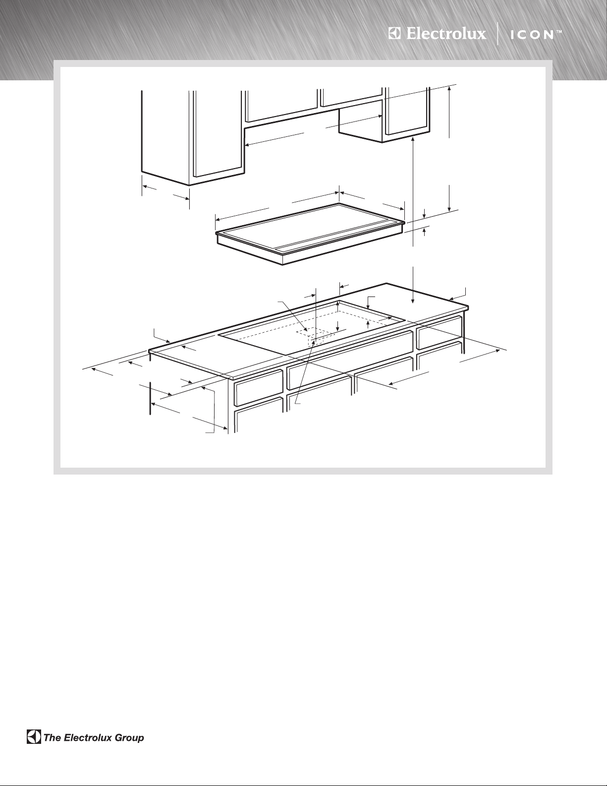
36" Electric Touch-Control Drop-In Cooktop Specifications
•
Product Weight – 50 Lbs.
•
Single phase 3- or 4-wire cable, 120/240 or 120/208 Volt,
60 Hertz AC only electrical supply with ground required on separate
circuit fused on both sides of line.
•
Connected Load (kW Rating) @ 240/208 Volts = 10.5/7.9kW
•
Amps @ 240/208 Volts = 44.0/38.0 Amps
•
Recommended Circuit Breaker – 50 Amps
•
Always consult local and/or national electric codes.
•
Allow 2" space below armored cable opening to clear electrical
cable and allow space for installation of junction box on wall at back
of cooktop.
•
Overhead cabinetry should not exceed a 13" maximum depth.
•
Allow 30" minimum clearance between top of cooktop and bottom of
unprotected wood or metal overhead cabinetry.
•
Absolute minimum horizontal distance between overhead cabinets
installed to either side of appliance must be no less than maximum width
of appliance.
•
Allow 24" minimum clearance when bottom of wood or metal overhead
cabinet is protected by not less than 1/8" flame-retardant millboard
covered with not less than No. 28 MGS sheet steel, 0.015" stainless
steel, 0.024" aluminum or 0.020" copper.
357/8"min.
36"max.
Approximate location
of junction box
•
Allow 1-1/2" minimum clearance between rear edge of cutout and
nearest combustible surface above countertop.
•
Allow 7-1/2" minimum clearance from edge of cooktop to nearest
combustible wall on either side of unit.
•
It is recommended that drawers not be used beneath cooktop.
•
To reduce risk of fire when using overhead cabinetry, install vent hood
that projects horizontally a recommended minimum of 5" beyond bottom
of cabinets.
•
Touch-Control Drop-In Cooktop model E36EC70FSS is approved to be
used over any Electrolux ICON™Single Wall Oven. (Refer to Electric
Cooktop Installation Over 30" Electric Single Wall Oven Specifications
and drawing on web.)
•
Touch-Control Drop-In Cooktop model E36EC70FSS is approved to
be used in combination with an Electrolux ICON™Downdraft Vent.
(Refer to Drop-In Cooktop/Downdraft Vent Countertop Preparation
Specifications and drawing on web.)
Note: For planning purposes only. Refer to Product Installation Guide
on the web at electroluxicon.com for detailed instructions.
•
USA
250 Bobby Jones Expressway •Augusta, GA 30907 •1-877-4electrolux (1-877-435-3287)
•
CANADA
E36EC70FSS 05/08 © 2008 Electrolux Home Products, Inc. Printed in the U.S.A.
5855 Terry Fox Way •Mississauga, ON L5V 3E4 •1-800-265-8352
•
electroluxicon.ca
•
electroluxicon.com
High standards of quality at Electrolux Home Products, Inc. mean we are
constantly working to improve our products. We reserve the right to change
specifications or discontinue models without notice.
Page 3
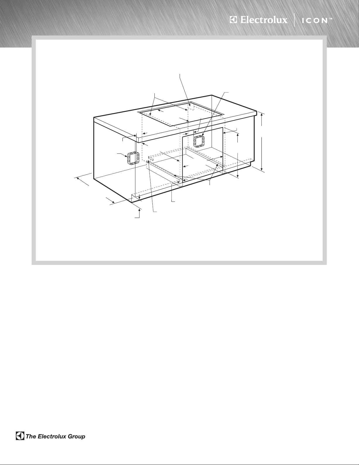
Electric Cooktop Installation
Over 30"Electric Single Wall Oven
For all approved electric cooktop models, cut minimum
4" x 4" opening in right cabinet side panel and/or filler
panel, to route armoured cable to junction box
Side filler panels necessary to isolate oven from
adjoining cabinets. Panel height may need to
be modified to accommodate the depth of approved
electric cooktop models
240/208V
Junction box
for electric
cooktop
Cooktop
cutout**
Approx. 3"
24"min.*
240/208V
Junction box
for wall oven
24" min.
cutout depth
4-1/2" maximum height allowed
from oven base to floor if cooktop
is installed directly over wall oven.
(5" maximum height allowed
with no cooktop.)
To route armoured cable to junction box through left cabinet side panel
and/or filler panel, cut minimum 4" x 4" opening in wood base and runner
*Critical dimension – MUST be applied
**For cooktop cutout dimensions refer to model-specific
product page or installation guide on web
30" Electric Single Wall Oven Under-Counter
Installation Specifications
•
Product Weights – (E30EW75GPS) 178 Lbs. / (E30EW75GSS) 175 Lbs.
•
Single phase 3- or 4-wire cable, 120/240 or 120/208 Volt, 60 Hertz
AC only electrical supply with ground required on separate circuit fused
on both sides of line.
•
Connected Load (kW Rating) @ 240/208 Volts = 4.0/3.0kW
•
Amps @ 240/208 Volts =16.6/14.4 Amps
•
Always consult local and/or national electric codes.
•
Minimum 23-1/4" clearance for oven door depth when open.
•
Minimum 24" deep cutout dimension is critical for proper installation,
to ensure that oven’s faceplate will fit flush against cabinet front.
•
Full oven base of solid plywood or similar material required, capable
of supporting 200 Lbs. Install over two runners and flush with toe plate.
•
Base must be level and cabinet front must be square with finish-cut
bottom edge.
•
Side filler panels necessary to isolate oven from adjoining cabinets.
•
Allow 5" maximum height from oven base to floor, if NO cooktop is
installed directly over wall oven.
Approx. 3"
Oven cutout
36"
min.
281/2" min.
7
/8" max.
28
1
/2"min.
28
29"max.
Install 3/4" full plywood base on 2 runners, flush
with toe plate, capable of supporting 200 lbs.
Unit will overlap cutout (minimum) edges by 1"
Electric Cooktop Installation Over
30" Electric Single Wall Oven Specifications
Single Wall Ovens are approved to be used beneath Electrolux ICON
electric cooktop models E36IC75FSS, E30IC75FSS, E36EC70FSS
and E30EC70FSS (electric cooktop models NOT approved for use in
this installation are E36EC75ESS, E36EC75HSS, E30EC65ESS and
E36EC65ESS).
For detailed Electric Cooktop installation, refer to model-specific
product page and installation guide on web.
•Side filler panels necessary to isolate oven from adjoining cabinets.
Panel height may need to be modified to accommodate the depth of
approved electric cooktop models.
•
To route armored cable to junction box, cut minimum 4" x 4" opening
in right cabinet side panel.
•
Allow 4-1/2" maximum height from oven base to floor, if cooktop is
installed directly over wall oven.
Note: For planning purposes only. Refer to Product Installation Guide
on the web at electroluxicon.com for detailed instructions.
™
•
USA
250 Bobby Jones Expressway •Augusta, GA 30907 •1-877-4electrolux (1-877-435-3287)
•
CANADA
EC_EW INST 03/08 © 2008 Electrolux Home Products, Inc. Printed in the U.S.A.
5855 Terry Fox Way •Mississauga, ON L5V 3E4 •1-800-265-8352
•
electroluxicon.ca
•
electroluxicon.com
High standards of quality at Electrolux Home Products, Inc. mean we are
constantly working to improve our products. We reserve the right to change
specifications or discontinue models without notice.
Page 4
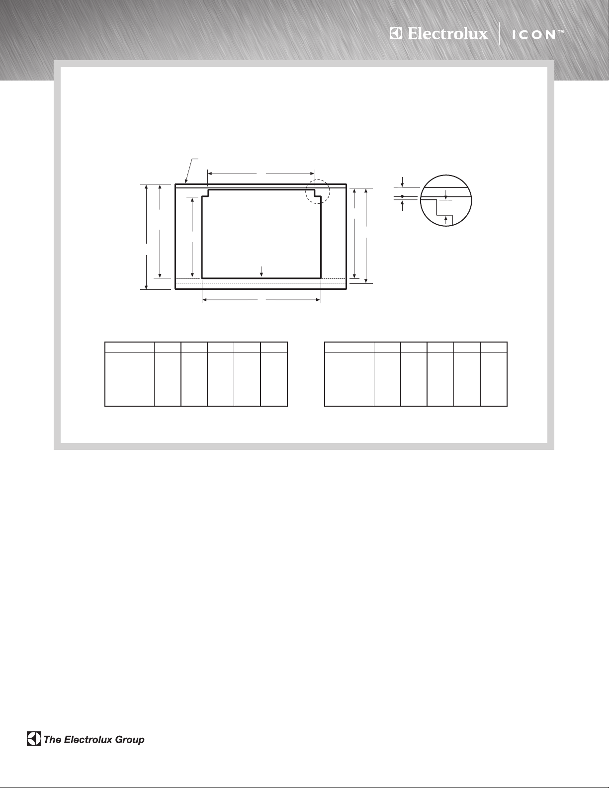
Drop-In Cooktop/Downdraft Vent
29/16"
Countertop Preparation
Countertop Preparation for 30" & 36" Drop-In Cooktop/Downdraft Vent Installation
For detailed cooktop and downdraft vent installation specifications, refer to model-specific product page and installation guide on web
Top
B
23 1/4"
min.
C
Vertical noncombustible surface - rear wall
25"
Flush with
back side of
cabinet front
A
E30DD75ESS/30" Cooktop Cutout Dimensions
30" Cooktops A B C D E
E30EC65ESS 30" 27
E30EC70FSS 30" 27
E30GC64ESS 27 1/2" 27 1/2" 19 7/8" 22 11/16" 23 11/16"
E30GC70FSS 28 1/2" 27 1/2" 19 3/4" 22 9/16" 23 9/16"
E30IC75FSS 29
1
/2" 20 3/8" 23 3/16" 24 3/16"
1
/2" 20 1/4" 23 1/16" 24 1/16"
3
/4" 27 1/2" 20 1/2" 23 5/16" 24 5/16"
Backsplash
3
/4" max.
D*
E**
1
/4" min.
flat ledge
* Overall flat ledge behind
backside of cabinet front
** Minimum flat surface
required to fit top surface
of cooktop and downdraft
vent cap
E36DD75ESS/36" Cooktop Cutout Dimensions
36" Cooktops A B C D E
E36EC65ESS 36" 33
E36EC70FSS 36" 33
E36GC65ESS 33 3/4" 33 3/4" 19 7/8" 22 11/16" 23 11/16"
E36GC70FSS 34 1/2" 33 3/4" 19 3/4" 22 9/16" 23 9/16"
E36IC75FSS 36" 33 3/4" 20 1/2" 23 5/16" 24 5/16"
3
/4" 20 3/8" 23 3/16" 24 3/16"
3
/4" 20 1/2" 23 5/16" 24 5/16"
Drop-In Cooktop/Downdraft Vent
Countertop Preparation Specifications
•
For detailed Drop-In Cooktop installation, refer to model-specific product
page and installation guide on web. Plan installation so that all required
minimum clearances between cooktop, overhead cabinets and adjacent
vertical walls are provided.
•
Position cooktop/vent cutout so all required minimum clearances
are met.
•
Minimum flat countertop area must meet or exceed combined overall
width and depth as shown.
•
Separate circuits required for cooktop and vent. (Refer to
product-specific electrical specifications.)
•
Always consult local and/or national electric codes. Check local building
codes for installation requirements, as they may vary per locale.
Downdraft Vent Specifications
•
For detailed Downdraft Vent installations, refer to model-specific
product page and installation guide on web.
•
Voltage Rating –120V / 60Hz/15 Amps
•
Connected Load (kW Rating) @120 Volts = 1.0kW
(For use on adequately wired 120V, dedicated circuit having 2-wire
service with a separate ground wire. Appliance must be grounded
•
Amps @120 Volts = 8.0 Amps
•
Vent unit outside of building only.
•
Vent must be installed in vertical orientation only.
•
1,600 CFM remote exhaust blower (part number 5304444802)
included with vent – shipped in separate box.
•
Do not use flexible duct. Round duct instead of rectangular duct
recommended, especially when elbows are required.
•
When multiple elbows are necessary, ensure a minimum of 24"
of straight duct between any two elbows.
•
Thermal breaks such as short section of nonmetallic duct, should
be used in areas of extreme cold.
•
For most efficient airflow exhaust, use a straight run or as few elbows
as possible.
•
Cold weather installations should have additional backdraft damper
installed.
•
Installing a Downdraft Vent in combination with any gas cooking surface
will affect optimum burner efficiency.
Note: For planning purposes only. Refer to Product Installation Guide
on the web at electroluxicon.com for detailed instructions.
for safe operation.)
•
USA
250 Bobby Jones Expressway •Augusta, GA 30907 •1-877-4electrolux (1-877-435-3287)
•
CANADA
DIC_DDV_PREP 03/08 © 2008 Electrolux Home Products, Inc. Printed in the U.S.A.
5855 Terry Fox Way •Mississauga, ON L5V 3E4 •1-800-265-8352
•
electroluxicon.ca
•
electroluxicon.com
High standards of quality at Electrolux Home Products, Inc. mean we are
constantly working to improve our products. We reserve the right to change
specifications or discontinue models without notice.
 Loading...