

Page 1

30" & 36" DUAL FUEL RANGE INSTALLATION INSTRUCTIONS
INSTALLATION INSTRUCTIONS
30" & 36" DUAL FUEL RANGE
INSTALLATION AND SERVICE MUST BE PERFORMED BY A QUALIFIED INSTALLER.
IMPORTANT: SAVE FOR LOCAL ELECTRICAL INSPECTOR'S USE.
READ AND SAVE THESE INSTRUCTIONS FOR FUTURE REFERENCE.
Canada
FOR YOUR SAFETY: Do not store or use gasoline or
other ammable vapors and liquids in the vicinity of this or any
other appliance.
Table of Contents
Important Safety Instructions .......................................2-4
Product Dimensions ....................................................... 5
Cabinet Dimensions ....................................................... 6
Cabinet Construction ...................................................... 7
Electrical Requirements...............................................7-8
Power Supply Cord......................................................... 8
Fuel Supply Requirements ............................................. 9
Important Notes to the Installer
1. Read all instructions contained in these installation
instructions before installing range.
2. Remove all packing material from the oven and the
drawer compartments before connecting the electrical
supply to the range.
3. The anti-tip bracket supplied with the appliance must
be installed.
4. Observe all governing codes and ordinances.
5. Be sure to leave these instructions with the consumer.
Connect Fuel Supply .................................................... 10
Install Oven Racks................................................... 11-12
Level the Range ........................................................... 13
Install Anti-Tip Bracket ............................................. 14-15
Install Burner Assemblies ........................................ 16-17
Check Oven Operation ................................................. 18
After Installation ............................................................ 18
Serial Plate Location (Model & Serial Number) ............ 18
Important Note to the Consumer
1. Keep these instructions with your owner's guide for
future reference.
2. When using any appliance generating heat, there are
safety precautions you must follow. These precautions
are explained in your Use and Care manual. Read
your manual carefully.
3. Be sure your appliance is installed and grounded by a
qualied installer or service technician.
Printed in the United States
P/N 809018701 (1611) Rev.A
English – pages 1-18
Español – pages 19-36
Français – pages 37-54
1
Page 2
30" & 36" DUAL FUEL RANGE INSTALLATION INSTRUCTIONS
IMPORTANT SAFETY INSTRUCTIONS
This appliance must be installed, grounded, and serviced by a qualied installer or service technician.
This manual contains important safety symbols and instructions. Please pay attention to these symbols and follow all
instructions given. Do not attempt to install or operate your appliance until you have read the safety precautions in this
manual. Safety items throughout this manual are labeled with a WARNING or CAUTION statement based on the risk type.
Warnings and important instructions appearing in this guide are not meant to cover all possible conditions and situations
that may occur. Common sense, caution, and care must be exercised with installing, maintaining, or operating your
appliance.
This is the safety alert symbol. It is used to alert you to potential personal injury hazards. Obey all safety messages
that follow this symbol to avoid possible injury or death.
Indicates a potentially hazardous situation which, if not avoided, may result in death or serious injury.
Indicates a potentially hazardous situation which, if not avoided, may result in minor or moderate injury.
IMPORTANT: Indicates installation, operation, maintenance, or valuable information that is not hazard related.
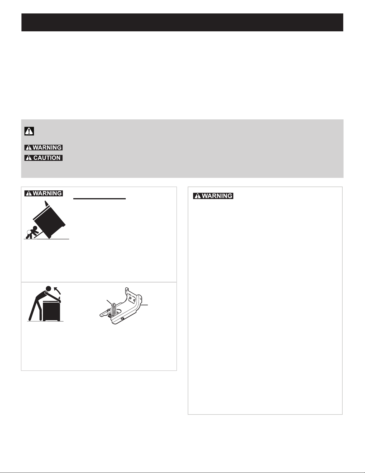
Tip Over Hazard
• A child or adult can tip the range
and be killed.
• Verify the anti-tip device has been
installed to floor or wall.
• Ensure the anti-tip device is re-engaged to floor or wall
when the range is moved.
• Do not operate the range without the anti-tip device in
place and engaged.
• Failure to follow these instructions can result in death or
serious burns to children and adults.
Range
leveling leg
Anti-tip
bracket
To check if the anti-tip bracket is installed properly, use both
arms to grasp the rear edge of the range back. Carefully
attempt to tilt range forward. When properly installed, the range
should not tilt forward.
Refer to the anti-tip bracket installation instructions supplied
with your range for proper installation.
If the information in this manual
is not followed exactly, a fire or explosion
may result causing property damage,
personal injury or death.
FOR YOUR SAFETY:
—Do not store or use gasoline or other
flammable vapors and liquids in the
vicinity of this or any other appliance.
—WHAT TO DO IF YOU SMELL GAS:
•Do not try to light any appliance.
•Do not touch any electrical switch; do
not use any phone in your building.
•Immediately call your gas supplier from
a neighbor's phone. Follow the gas
supplier's instructions.
•If you cannot reach your gas supplier,
call the fire department.
—Installation and service must be
performed by a qualified installer,
servicer or the gas supplier.
2
Page 3
30" & 36" DUAL FUEL RANGE INSTALLATION INSTRUCTIONS
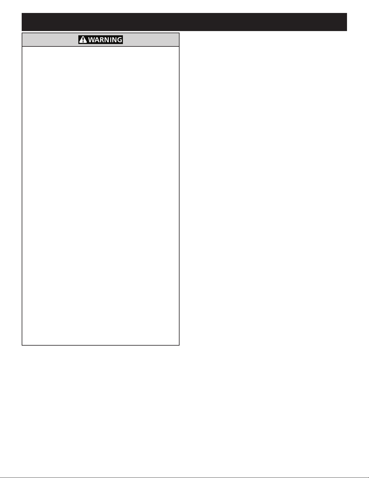
• Excessive Weight Hazard--Use two or more
people to move and install range. Failure to follow
this instruction can result in back or other injury.
• Storage In or On Appliance—Flammable
materials should not be stored in an oven or
microwave, near surface burners or elements, or
in the storage or warmer drawer (if equipped). This
includes paper, plastic, and cloth items, such as
cookbooks, plastic ware, and towels, as well as
ammable liquids. Do not store explosives, such as
aerosol cans, on or near the appliance.
• Do not leave children alone - Children should
not be left alone or unattended in the area where
appliance is in use. They should never be allowed
to sit or stand on any part of the appliance,
including the storage drawer, lower broiler drawer,
warmer drawer, or lower double oven.
• Do not store items of interest to children in the
cabinets above the appliance or on the backguards
of ranges. Children climbing on or near the
appliance to reach items could be seriously injured.
• Stepping, leaning, or sitting on the door or drawers
of this appliance can result in serious injuries and
also cause damage to the appliance.
• Do not use oven or warmer drawer (if equipped) for
storage.
• Never use your appliance as a space heater to
heat or warm the room. Doing so may result in
carbon monoxide poisoning and overheating of the
appliance.
• Do not store or use gasoline or other ammable
vapors and liquids in the vicinity of this or any other
appliance.
• Air curtain or other overhead range hoods which
operate by blowing a downward air ow onto a
range or cooktop, shall not be used in conjunction
with gas ranges or cooktops other than when the
range or cooktop and hood have been designed,
tested, and listed by an independent test laboratory
for use in combination with each other.
IMPORTANT INSTRUCTIONS FOR UNPACKING AND
INSTALLATION
Read and follow the below instructions and precautions
for unpacking, installing, and servicing your appliance:
• Destroy the carton and plastic bags after unpacking the
appliance. Never allow children to play with packaging
material. Do not remove the wiring label and other
literature attached to the appliance. Do not remove
model/serial number plate.
• Cold temperatures can damage the electronic control.
When using this appliance for the rst time, or when the
appliance has not been used for an extended period of
time, be sure the appliance has been in temperatures
above 32ºF (0ºC) for at least 3 hours before turning on
the power to the appliance.
• Never modify or alter the construction of the appliance
by removing the leveling legs, panels, wire covers, antitip brackets/screws, or any other part of the appliance.
• Proper Installation—Be sure your appliance is properly
installed and grounded by a qualied technician. In the
United States, install in accordance with the National
Fuel Gas Code ANSI Z223.1/NPFA No. 54, latest
edition and National Electrical Code NFPA No. 70
latest edition, and local electrical code requirements.
In Canada, install in accordance with CAN/CGA
B149.1 and CAN/CGA B149.2 and CSA Standard
C22.1, Canadian Electrical code, Part 1-latest editions
and local electrical code requirements. Install only
per installation instructions provided in the literature
package for this appliance.
• The installation of appliances designed for
manufactured (mobile) home installation must
conform with Manufactured Home Construction and
Safety Standard, title 24CFR, part 3280 [Formerly
the Federal Standard for Mobile Home Construction
and Safety, title 24, HUD (part 280)] or when
such standard is not applicable, the Standard for
Manufactured Home Installation 1982 (Manufactured
Home Sites, Communities and Setups), ANSI Z225.1/
NFPA 501A-latest edition, or with local codes in United
States and with CAN/CSA-Z240 MH in Canada.
• Before installing the range in an area covered with
linoleum or any other synthetic oor covering, make
sure the oor covering can withstand heat at least
90°F (32.2°C) above room temperature without
shrinking, warping or discoloring. Do not install the
range over carpeting unless you place an insulating
pad or sheet of ¼" (0,64 cm) thick plywood between
the range and carpeting.
• Make sure the wall coverings and cabinet materials
around the range can withstand the heat generated by
the appliance.
• To eliminate the risk of burns or re by reaching over
heated surface units, cabinet storage space above the
surface unit should be avoided. If cabinet storage is to
be provided the risk can be reduce by installing a range
hood that projects horizontally a minimum of 5 inches
beyond the bottom of the cabinet.
• Do not obstruct airow at the oven vent, around
the base, or beneath the lower front panel of the
appliance. This appliance requires fresh air for proper
operation.
• Be sure to have an appropriate foam-type re
extinguisher available, visible, and easily accessible
located near the appliance.
3
Page 4

30" & 36" DUAL FUEL RANGE INSTALLATION INSTRUCTIONS
SPECIAL INSTRUCTIONS FOR APPLIANCES
INSTALLED IN THE STATE OF MASSACHUSETTS
This appliance can only be installed in the State of
Massachusetts by a Massachusetts licensed plumber or
gas tter. When using a exible gas connector, it must
not exceed 3 feet (36 inches) in length. A "T" handle type
manual gas valve must be installed in the gas supply line
to this appliance.
CONVERSION TO L.P. GAS
This appliance allows for conversion to Liqueed
Petroleum (L.P.) Gas.
Personal injury or death from electrical
shock may occur if the conversion to L.P. gas is not
made by a qualied installer or electrician. Any additions,
changes or conversions required in order for this
appliance to satisfactorily meet the application needs
must be made by a qualied technician.
If L.P. conversion is needed, contact your local L.P.
Gas provider for assistance. The L.P. conversion kit is
provided with this appliance and is located on the lower
REAR (back side) panel of the range. Before installing
the kit be sure to read the L.P. Installation Instructions
and follow them carefully when making the installation.
IMPORTANT INSTRUCTIONS FOR SERVICE AND
MAINTENANCE
• Do not repair or replace any part of the appliance
unless specically recommended in the manuals. All
other servicing should be done only by a qualied
technician. This reduces the risk of personal injury
and damage to the appliance.
• Always contact your dealer, distributor, service agent,
or manufacturer about problems or conditions you do
not understand.
• Ask your dealer to recommend a qualied technician
and an authorized repair service. Know how to
disconnect the power to the appliance at the circuit
breaker or fuse box in case of an emergency.
• Remove the oven door from any unused oven if it is to
be stored or discarded.
• Do not touch a hot oven light bulb with a damp cloth.
Doing so could cause the bulb to break. Handle
halogen lights (if equipped) with paper towels or soft
gloves. Disconnect the appliance or shut off the power
to the appliance before removing and replacing the
bulb.
4
Page 5
30" & 36" DUAL FUEL RANGE INSTALLATION INSTRUCTIONS
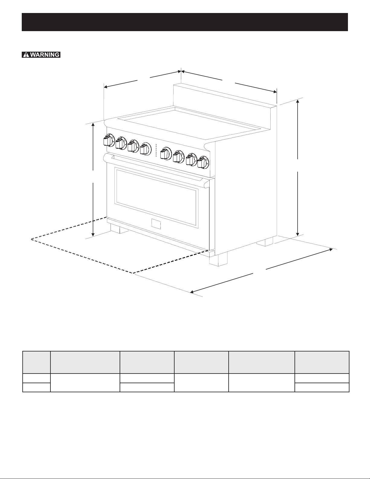
Product Dimensions
Do not install the unit in the cabinet before reading next two pages.
D
C
B
A
E
Figure 1: Product Dimensions
C. DEPTH TO
MODEL A. HEIGHT B. WIDTH
30"
36" 35 7/8" (91.1 cm) 48 3/8" (122.9 cm)
41 5/8" (105.7 cm) Min.
42 5/8" (108.3 cm) Max.
29 7/8" (75.9 cm)
FRONT OF
RANGE
27 1/2" (69.9cm)
D. HEIGHT OF
COOKTOP
35 3/4" (90.8 cm) Min.
36 3/4" (93.3 cm) Max.
E. DEPTH WITH
DOOR OPEN
46 1/4" (117.5 cm)
5
Page 6
30" & 36" DUAL FUEL RANGE INSTALLATION INSTRUCTIONS
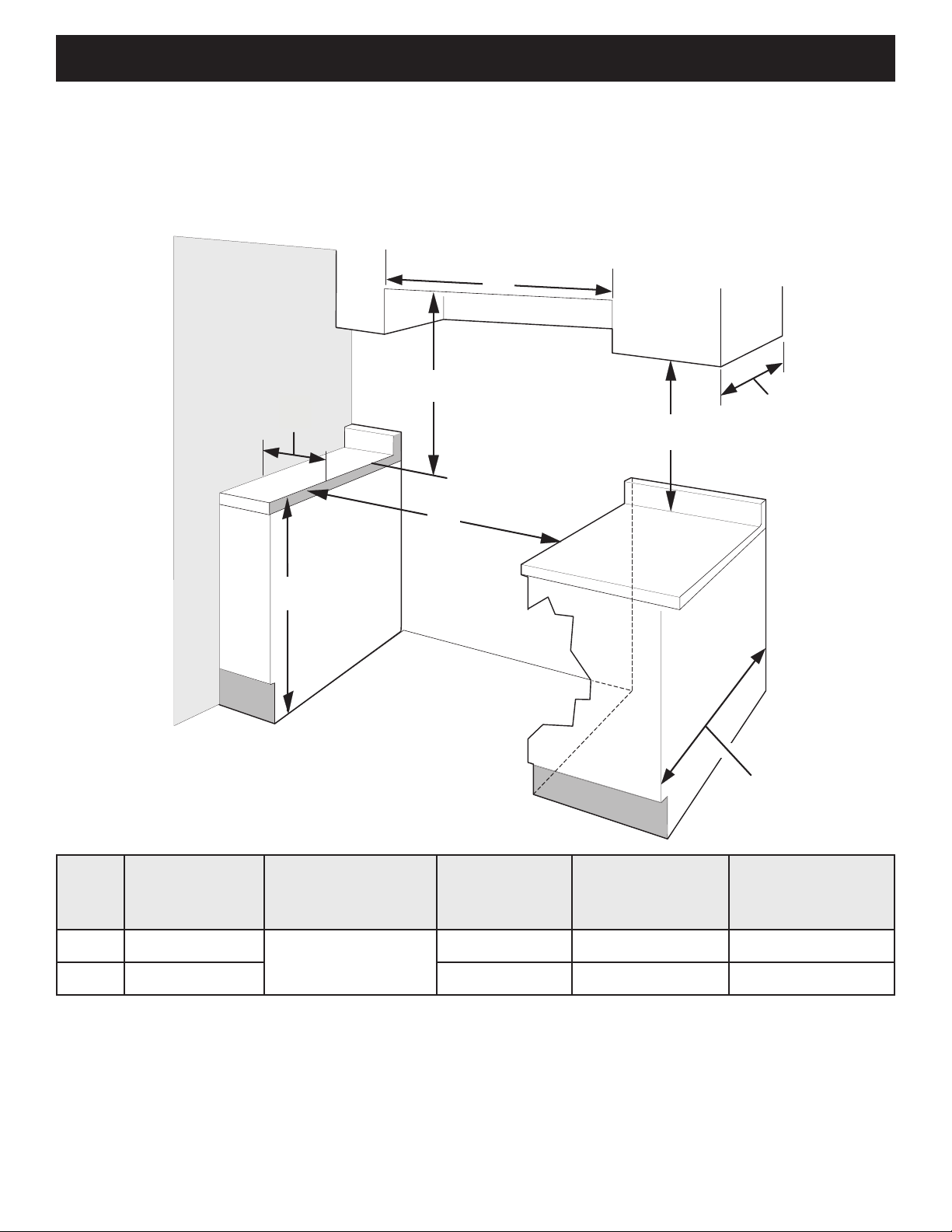
Cabinet Dimensions
Clearances and Dimensions
• Provide adequate clearances between the appliance and adjacent combustible surfaces.
• Location - Check location where the appliance will be installed. Check for proper electrical supply and oor
stability.
• Dimensions shown must be used. Given dimensions provide minimum clearance. Contact surface must be
solid and level.
J
H
G
I
F
Figure 2: Cabinet Dimensions
13" Max.
(33 cm Max.)
18" Min.
(45.7 cm Min.)
24" Min.
(61 cm Min.)
24½" max.
(62.2 cm Max.)
MODEL
30" 30 1/16" (76.4 cm)
36" 36 1/16" (91.6 cm) 7" (17.8 cm) Min. 36" (91.4 cm) Min. 36" (91.4 cm) Min.
NOTES:
1. Do not seal the range to the side cabinets.
2. Clearance from adjacent walls or other vertical surfaces or structures such as cabinets.
3. Measurements listed are minimum clearances between the cooktop and the bottom of the cabinet.
4. 0" clearance between range and cabinets or vertical surfaces that are below the cooktop height.
5. 0" clearance between range back and rear wall or cabinet.
F. MINIMUM
CUTOUT WIDTH
G. HEIGHT OF
COUNTERTOP
36" (91.4 cm) Standard
35 3/4" (90.8 cm) Min.
H. CLEARANCE
FROM SIDE
WALLS
5" (12.7 cm) Min. 30" (76.2 cm) Min. 30" (76.2 cm) Min.
6
2
I. CLEARNACE
FROM COOKTOP
AND CABINET
BOTTOM
3
J. CLEARANCE
WIDTH OF
OVERHEAD
CABINETS
Page 7

30" & 36" DUAL FUEL RANGE INSTALLATION INSTRUCTIONS
Follow instructions for
the type of installation you have
Center
Line of
Range
1
Cabinet Construction
To eliminate the risk of burns or re by
reaching over heated surface units, do not have cabinet
storage space above the range. If there is cabinet storage
space above range, reduce risk by installing a range
hood that projects horizontally a minimum of 5" (12.7 cm)
beyond the bottom of the cabinet.
Figure 3: Cabinet construction
1.1
Installation: Cabinet on Both Sides
1. If range will be installed with a cabinet on both sides,
Draw a center line on the oor between the cabinets
(Figure 5).
2. If back of range will not be ush with the wall (the
location of the outlet may not allow the range to be
positioned against the wall), draw a line on the oor
where the back edge of the range will be.
3. Install anti-tip brackets (see "Anti-Tip Bracket
Installation").
2
Electrical Requirements
Electrical Shock Hazard –Electrical ground is
required on this appliance. Use only the power cord
supplied with the appliance. Improper connections and
grounding may result in electric shock, damage to the
appliance, personal injury, re or death.
Grounding Requirements
This appliance must be installed and grounded by a
qualied technician.
In the United States, install in accordance with the National
Fuel Gas Code ANSI Z223.1/NPFA No. 54, latest edition
and National Electrical Code NFPA No. 70 latest edition,
and local electrical code requirements. In Canada, install in
accordance with CAN/CGA B149.1 and CAN/CGA B149.2
and CSA Standard C22.1, Canadian Electrical code, Part
1-latest editions and local electrical code requirements.
For personal safety, this appliance must be properly
grounded. For maximum safety, the power cord must
be plugged into an electrical outlet that is the correct
voltage, is correctly polarized and properly grounded
in accordance with local codes. It is the personal
responsibility of the consumer to have the appropriate
outlet with the correct, properly grounded wall receptacle
installed by a qualied electrician.
This appliance is intended to be plugged into a 14-50R
standard wall receptacle.
Electrical Wall Receptacle
1.2
Installation: Cabinet on One Side Only
1. If range will be installed with a cabinet on one side
only, move the range into nal position.
2. Draw a line on the oor along the side of the range
that is not against the cabinet. If back of range will
not be ush with the wall (the location of the outlet
may not allow the range to be positioned against the
wall), draw a line on the oor where the back edge of
the range will be.
3. Install anti-tip brackets (see "Anti-Tip Bracket
Installation").
1.3
Installation: Without Cabinet
1. If range will not be installed against a cabinet, move
range into nal position.
2. Mark on the oor along both sides of the range.
If back of range will not be ush with the wall (the
location of the outlet may not allow the range to be
positioned against the wall), draw a line on the oor
where the back edge of the range will be.
3. Install anti-tip brackets (see "Anti-Tip Bracket
Installation").
Required for all installations
4-Wire receptacle (14-50R)
When only 4-wire, single phase, 240 volt, 60 Hz, AConly electrical supply is available, this appliance requires
minimum 40 amp circuit protection fused on both sides of
the line.
A time-delay circuit breaker or fuse is recommended.
Be sure the wall receptacle is within reach of the
appliance's nal installed location.
Do not pinch the power supply cord between the range
and the wall.
7
Page 8

30" & 36" DUAL FUEL RANGE INSTALLATION INSTRUCTIONS
12”
(30.5 cm)
8”
(20.3 cm)
Recommended Wall Outlet Installation
Locations
Suggested location of the wall outlet is shown in Figure 4
for 30" models and in Figure 5 for 36" models. The
outlet may also be located in the lower left corner of the
adjacent right cabinet, as shown in Figure 6
Center
Line of
Range
10"
(25.4 cm)
7" Max.
(17.8 cm Max.)
Locate Electrical Hook-up
Inside Shaded Area
Figure 4: 30" Models Outlet Location
WALL
FLOOR
Center
Line of
Range
Power Supply Cord
3
Electrical Shock Hazard –Do not attempt to install
the appliance directly to a junction box, modify the
factory-installed cord, or connect a different power
cord to the appliance. If the wall outlet is not sufcient
to support the requirements of this appliance, it is the
responsibility of the consumer to have the appropriate
outlet installed by an electrician. Improper installation
and electrical connections can result in electric shock,
damage to the appliance, personal injury, re, or death.
This appliance is equipped with a factory-connected,
4-wire power supply cord (Figure 7). This cord is rated
at 240 volts, 40 amps, and temperature rated at 194°F
(90°C). This cord is UL/CSA listed and has been tested
and approved for use with this appliance.
Center
Line of
Range
14"
(35.6 cm)
(1 cm Max.)2.7
5" Max.
WALL
Locate Electrical Hook-up
FLOOR
Inside Shaded Area
Center
Line of
Range
Figure 5: 36" Models Outlet Location
Figure 7: Factory connected power supply cord
Appliance Rating* Power Supply
Rating
120/240 Volts 120/208 Volts Amps
1-10 kW 0-7.6 kW 30
8.8-16.5 kW 7.8-12.5 kW 40 or 50
16.6-22.5 kW 12.6-18.5 kW 50
* The NEC calculated load is less than the total connec-
ted load listed on the serial plate.
Figure 6: Adjacent Cabinet Outlet Location
8
Page 9
30" & 36" DUAL FUEL RANGE INSTALLATION INSTRUCTIONS
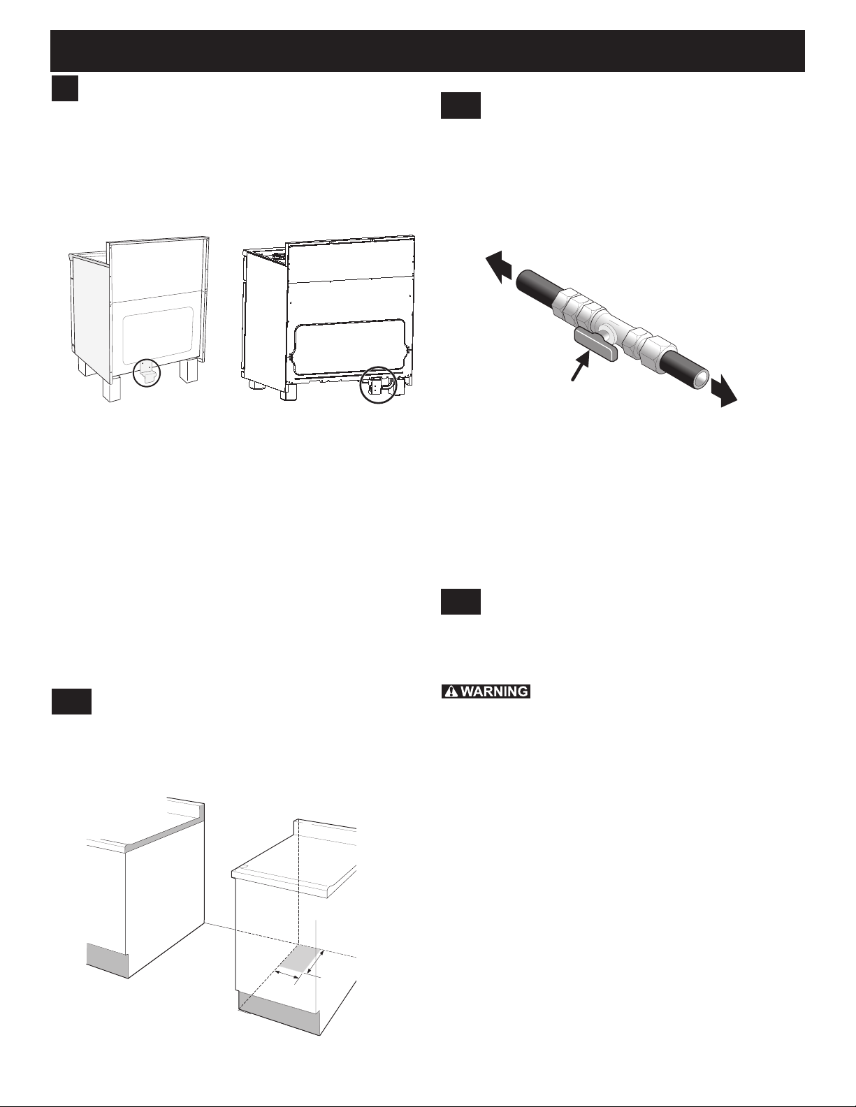
Shutoff Valve -
Open position
to appliance
to gas supply line
12”
(30.5 cm)
8“
(20.3 cm)
Fuel Supply Requirements
4
This unit is designed to operate on 4"(10.16 cm) water
column (1.0 kPa) natural gas manifold pressure.
A convertible pressure regulator is connected to the
range manifold and MUST be connected in series with
the gas supply line. The regulator is located as shown on
Figure 8 and it is accessible from front of the range.
30" Models 36" Models
Figure 8: Regulator locations
4.2
Shutoff Valve
The supply line should be equipped with an approved
shutoff valve as shown in Figure 10. This valve should
be located in the same room as the range and should
be in a location that allows ease of opening and closing.
Do not block access to the shutoff valve. The valve is for
turning on or shutting off gas to the appliance.
Figure 10: Shutoff valve
For proper operation, the maximum inlet pressure to
the regulator should be no more than 14" (35.56 cm) of
water column pressure (3.5 kPa).
The inlet pressure to the regulator must be at least
1" (0.25 kPa) greater than the regulator manifold
pressure setting. The regulator is set for 4" (10.16 cm)
water column (1.0 kPa) Natural gas manifold pressure;
the inlet pressure must be at least 5" (12.60 cm) water
column (1.25 kPa) Natural gas.
For operation at 2000 ft. above sea level, appliance rating
is reduced by 4 percent for each additional 1000 ft.
4.1
The gas supply piping can be through the side wall of the
right cabinet. The right side cabinet is an ideal location
for the main shutoff valve, if the range is installed within
cabinet storage space.
Gas Supply Location
The gas supply between the shutoff valve and the
regulator may be connected by rigid piping or by A.G.A./
C.G.A.- approved exible metallic union-connected
piping where local codes permit use.
The user must know the location of the main shutoff
valve and have easy access to it.
4.3
Conversion to Liqueed Petroleum
(L.P.) Gas
This appliance allows for conversion to Liqueed
Petroleum (L.P.) Gas.
Personal injury or death from electrical
shock may occur if the conversion to L.P. gas is not
made by a qualied installer or electrician. Any additions,
changes or conversions required in order for this
appliance to satisfactorily meet the application needs
must be made by a qualied technician.
If L.P. conversion is needed, contact your local L.P.
Gas provider for assistance. The L.P. conversion kit is
provided with this appliance and is located on the lower
REAR (back side) panel of the range. Before installing
the kit be sure to read the L.P. Installation Instructions
and follow them carefully when making the installation.
For LP/Propane gas, the regulator must be set for
10"(25.4 cm) water column (2.5 kPa) manifold pressure;
the inlet pressure must be at least 11"(27.9 cm) water
column (2.75 kPa).
Figure 9: Recommended gas supply location
9
Page 10

30" & 36" DUAL FUEL RANGE INSTALLATION INSTRUCTIONS
Flare
Union
Flare
Union
GAS FLOW
Manual
Shutoff
Valve
Pressure
Regulator
On
Off
Flexible
Connector
Access
Cap
Nipple Nipple
Connect Fuel Supply
5
5.1
Fuel Supply Connection
This appliance must be installed,
grounded, and serviced by a qualied installer or service
technician.
Do not make connections too tight. The
regulator is die cast. Overtightening may crack the
regulator resulting in a gas leak and possible re or
explosion.
This appliance includes a regulator. The gas supply line
requires the following parts which are not supplied with
the appliance:
• Manual shutoff valve
• 1/2" nipples (2)
• 1/2" are union adapter (2)
• Flexible connector
The gas supply line to the shutoff valve should be
1/2"(1.27 cm) or 3/4"(1.9 cm) solid pipe.
Install the gas supply pipe to the pressure regulator in
the order shown in Figure 11. All connections should be
tightened with a wrench.
5.2
Check For Leaks
Do not use a ame to check for leaks from
gas connections. Checking for leaks with a ame may
result in a re or explosion.
After connecting the range to the gas supply, check the
system for leaks with a manometer. If a manometer is not
available, turn on the gas supply and use a liquid leak
detector (or soap and water) at all joints and connections
to check for leaks. Leaks will be indicated by bubbles
appearing at the connections or joints.
All openings in the wall or oor where the range is to be
installed must be sealed.
1. Tighten all connections if necessary to prevent gas
leakage in the cooktop or supply line.
2. Disconnect this range and its individual shutoff valve
from the gas supply piping system during any pressure
testing of the system at test pressures greater than
1/2 psig (3.5 kPa or 14"(35.56 cm) water column).
3. Isolate the range from the gas supply piping system by
closing its individual manual shutoff valve during any
pressure testing of the gas supply piping system at
test pressures equal to or less than 1/2 psig (3.5 kPa
or 14"(35.56 cm) water column).
Figure 11: Fuel supply connection ow
When using exible gas conduit on the range, allow
sufcient slack to pull the range outside the cutout for
cleaning or servicing.
Use pipe-joint compound made for use with Natural and
LP/Propane gas to seal all gas connections. If exible
connectors are used, be certain connectors are not
kinked.
Do not allow the exible conduit to get pinched between
the wall and the range.
10
Page 11
30" & 36" DUAL FUEL RANGE INSTALLATION INSTRUCTIONS
Install the Oven Racks
6
6.1
30" Models - Ladder Rack Supports
To aid installation of the porcelain oven rack supports,
apply a thin layer of cooking oil to all the prongs of the
supports as shown in Figure 12.
Figure 12: Ladder rack supports - oil areas
1. Hold the oven rack support at a slight angle and insert
prongs into the holes at the top of the oven cavity
(Figure 13).
2. Lift the rack into the top holes, aligning the bottom
prongs with the bottom holes (Figure 13).
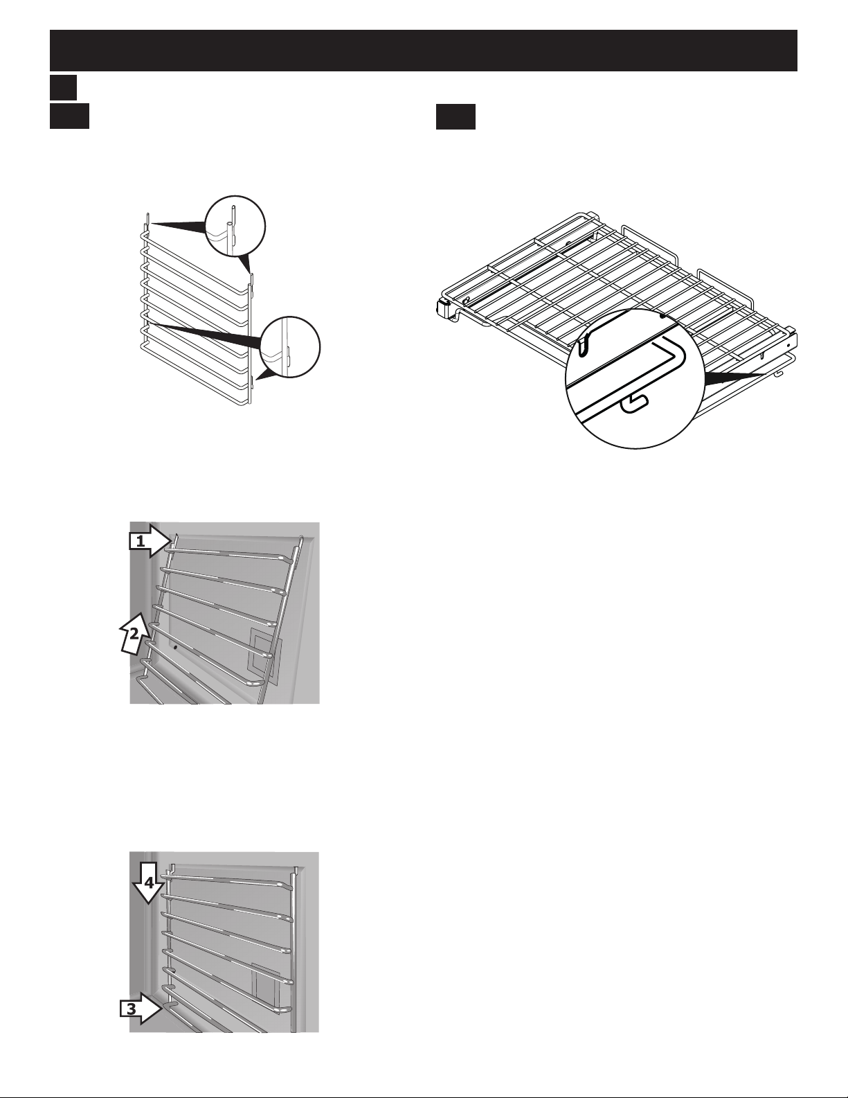
6.2
30" Models - Glide Racks
The glide racks install like other oven racks.
The glide rack stop (Figure 15) must be inside the ladder
support for the rack to slide in and out properly.
Figure 15: Glide rack stop
Place the oven rack on the rack supports. Tilt the back of
the rack upward slighly to get the stop into place inside the
ladder rack. Slide the oven rack back into place
Be sure to slide the rack all the way in so that the back of
the rack stops by meeting the vertical support of the ladder
rack.
To prevent possible damage to the oven, do not attempt to
close the oven door until all oven racks are fully positioned
inside the oven cavity.
Figure 13: Ladder rack supports - top prongs
3. Once the upper prongs are in place, hold the oven
rack support ush with the oven side and insert the
bottom prongs into the bottom holes (Figure 14).
4. Slide the bottom prongs down into the lower holes.
Some force may be required to set the rack into place
(Figure 14).
Figure 14: Ladder rack supports - bottom prongs
11
Page 12
30" & 36" DUAL FUEL RANGE INSTALLATION INSTRUCTIONS
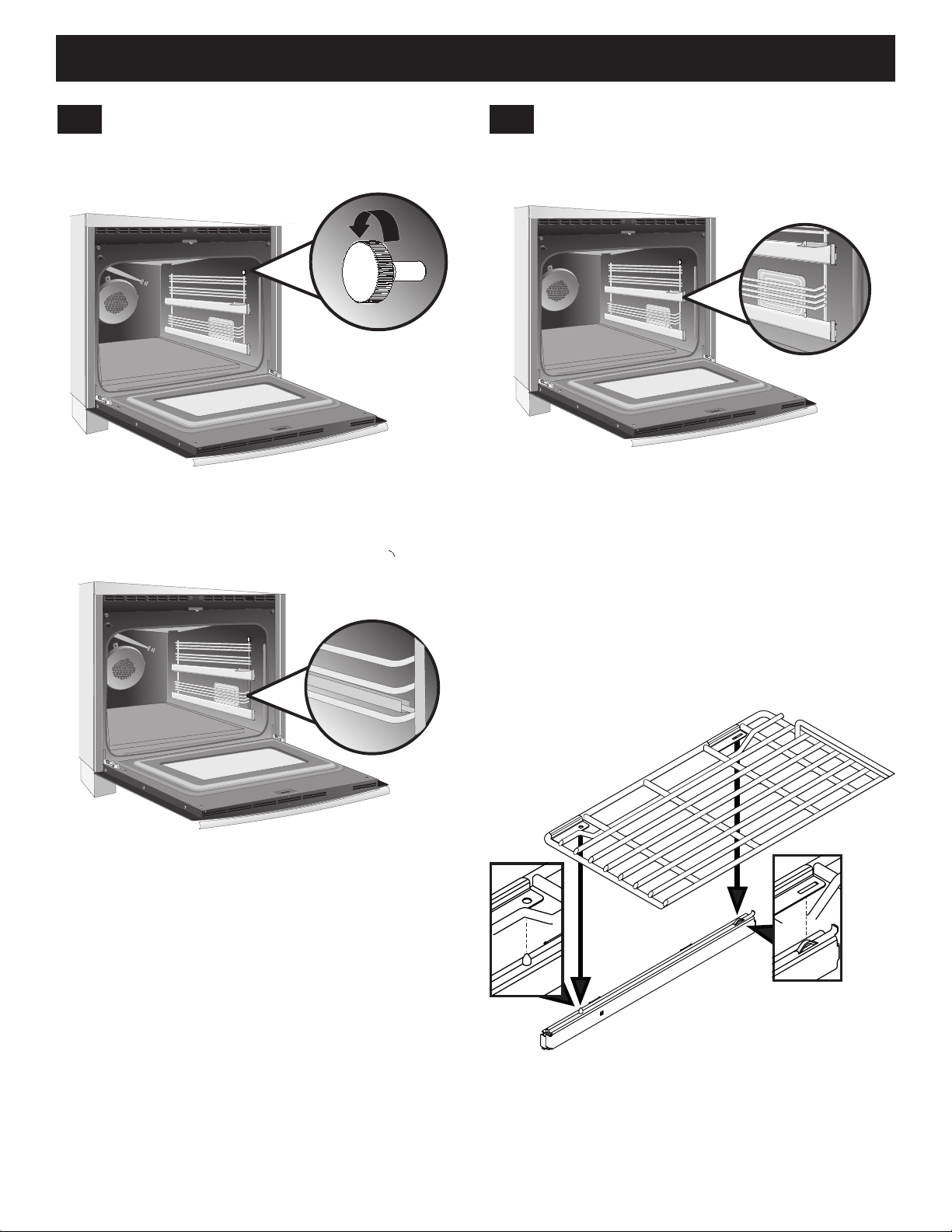
6.3
36" Models - Ladder Rack Supports
1. Remove the thumb screws located on each side of the
oven cavity (see Figure 16).
Figure 16: Ladder rack thumb screw
2. Place the ladder racks into the support brackets located on the oven sides (see Figure 17).
6.4
36" Models - Glide Racks
On 36" models, the glide tracks for the gliding oven racks
come pre-installed on the ladder rack supports (see
Figure 18).
Figure 18: Ladder rack glides
The glide racks appear slightly different than the at
racks (see Figre 19). Only the glide racks can be
installed onto the glide tracks.
1. Extend the two bottom glides fully out of the oven.
2. Place the glide rack on top of the glides.
3. Near the back of the rack, t the rack slot onto the
track tabs. Near the front of the rack, t the track pin
into the hole on the rack (see Figure 19).
4. Once the rack is installed, it can be pulled in and out
of the oven cavity on the glide tracks. Repeat for the
top set of glides.
Figure 17: Ladder rack supports
3. Replace the screws removed in Step 1.
Figure 19: Installing glide racks
The glide racks can only be used in these positions. The
racks may be removed from the tracks and used like a
regular at rack on all the other rack positions.
Insert regular at oven racks in any desired position.
12
Page 13
30" & 36" DUAL FUEL RANGE INSTALLATION INSTRUCTIONS
7
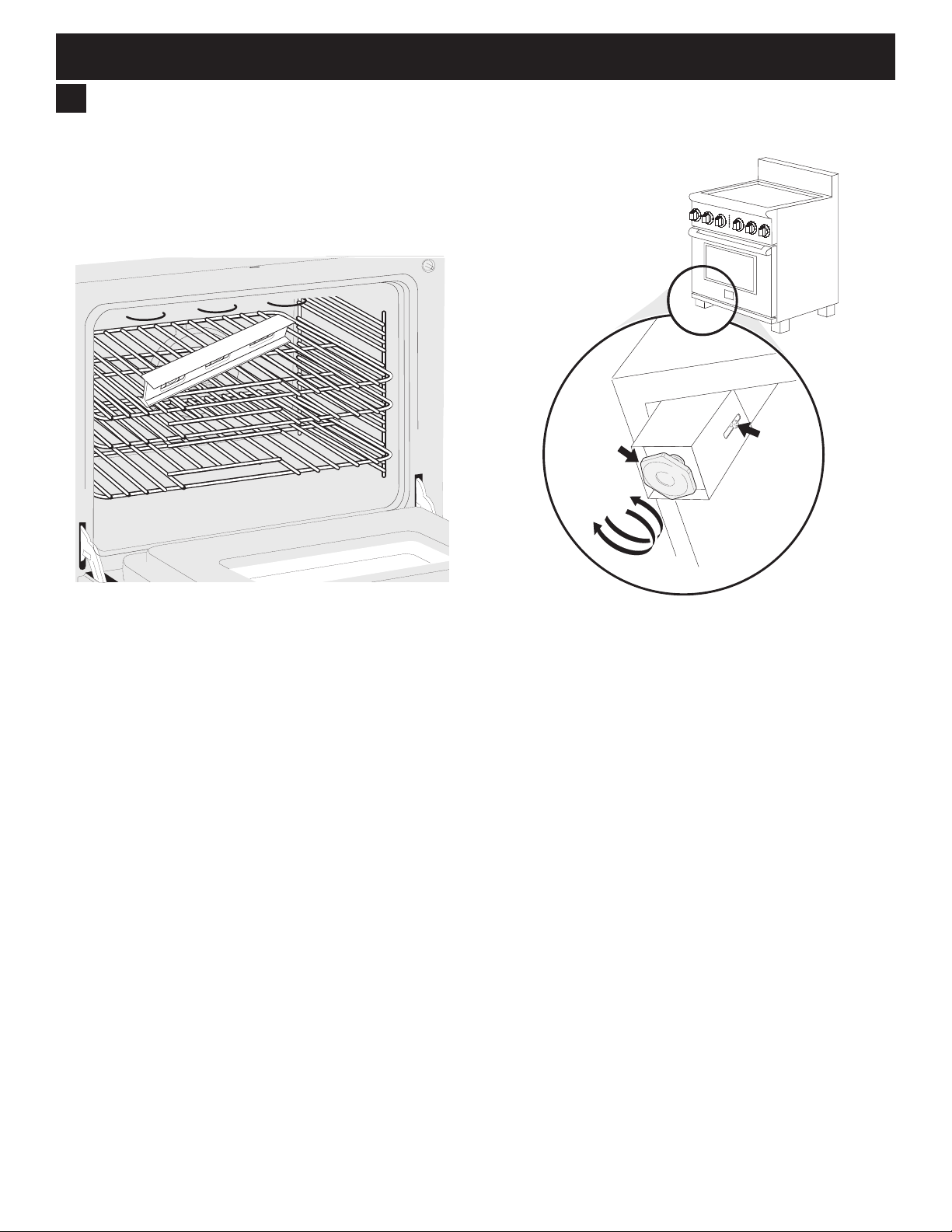
Level the Range
Level the range and set cooktop height before
installation in the cut-out opening (if applicable).
1. Install an oven rack in the center of the oven.
2. Place a level on the rack (Figure 20). Take 2
readings with the level placed diagonally in one
direction and then the other.
3. Level the range, if necessary, by adjusting the 4 leg
levelers with a wrench (Figure 21).
Base of Range
Figure 20: Use the oven racks to level appliance
Leveling leg
Raise
Lower
Figure 21: Adjusting appliance height
4. Slide range into cut-out opening and double check
for levelness. If the range is not level, pull unit out
and readjust leveling legs, or make sure oor is level.
Decorative
Leg Screw
13
Page 14
30" & 36" DUAL FUEL RANGE INSTALLATION INSTRUCTIONS
8
Install Anti-Tip Bracket
To reduce the risk of tipping the appliance,
the appliance must be secured to the oor by the properly
installed anti-tip bracket and screws packed with the
range. These parts are located in the oven. Failure to
install the anti-tip bracket will allow the range to tip over if
excessive weight is placed on an open door or if a child
climbs on it. Serious injury might result from spilled hot
liquids or from the range itself.
If range is ever moved to a different location, the antitip brackets must also be moved and installed with the
range.
Tools Required:
• Adjustable Wrench
• Ratchet
• Drill & 1/8" (0.32 cm) bit
• 5/16" (0.8 cm) Nut driver
• Level
Tip Over Hazard
• A child or adult can tip the range
and be killed.
• Verify the anti-tip device has been
installed to floor or wall.
• Ensure the anti-tip device is re-engaged to floor or wall
when the range is moved.
• Do not operate the range without the anti-tip device in
place and engaged.
• Failure to follow these instructions can result in death or
serious burns to children and adults.
Range
leveling leg
Anti-tip
bracket
8.1
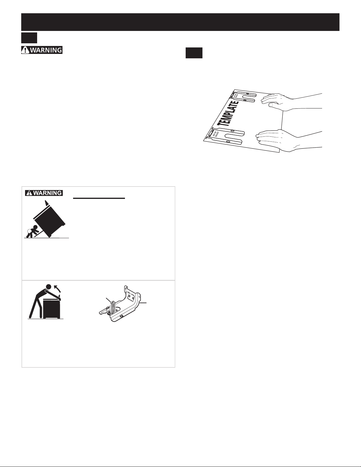
Locate the Bracket Using the Template
Bracket may be located on either the left or right side of
the range. Mark the oor or wall where left or right side of
the range will be located.
Figure 22: Bracket template
If rear of range is against the wall or no further than 1/2”
(1.3 cm) from wall when installed, you may use the wall
or oor mount method. If moulding is installed and does
not allow the bracket to t ush against the wall, remove
moulding or mount bracket to the oor.
For wall mount, locate the bracket by placing the back
edge of the template against the rear wall and the side
edge of template on the mark made referencing the side
of the range. Place bracket on top of template and mark
location of the screw holes in wall.
If rear of range is further than 1/2” (1.3 cm) from the wall
when installed, attach bracket to the oor. For oor mount,
locate the bracket by placing back edge of the template
where the rear of the range will be located.
Mark the location of the screw holes shown in template.
To check if the anti-tip bracket is installed properly, use both
arms to grasp the rear edge of the range back. Carefully
attempt to tilt range forward. When properly installed, the range
should not tilt forward.
Refer to the anti-tip bracket installation instructions supplied
with your range for proper installation.
14
Page 15

30" & 36" DUAL FUEL RANGE INSTALLATION INSTRUCTIONS
Leveling Leg
Anti-Tip Bracket
Floor Mount
8.2
Drill Pilot Holes and Fasten Bracket
Drill a 1/8” pilot hole where screws are to be located.
If bracket is to be mounted to the wall, drill pilot hole at
an approximate 20° downward angle. If bracket is to
be mounted to masonry or ceramic oors, drill a 3/16”
(4.8 mm) pilot hole 1-3/4” deep.
Figure 23: Drill pilot holes
The screws provided may be used in wood or concrete
material. Use a 5/16” nut-driver or at head screwdriver to
secure the bracket in place.
8.3
Check Level and Position the Range
Check the level of the nal installation. Note: A minimum
clearance of 1/8” is required between the bottom of the
range and the levelling leg to allow room for the bracket.
Use a spirit level to check your adjustments.
1/8" Minimum
Figure 24: Fastening the bracket
Wall Mount
Figure 25: Use the oven racks to level appliance
Slide range into position.
Wall Plate
Figure 26: Slide appliance into bracket
To check if the anti-tip bracket is installed properly,
use both arms and grasp the rear edge of range back.
Carefully attempt to tilt range forward. When properly
installed, the range should not tilt forward.
If range is moved to a different location, the anti-tip
brackets must also be moved and installed with the range.
15
Page 16
30" & 36" DUAL FUEL RANGE INSTALLATION INSTRUCTIONS
9
Install Burner Assemblies
To prevent are-ups use the cooktop with all burner caps properly installed.
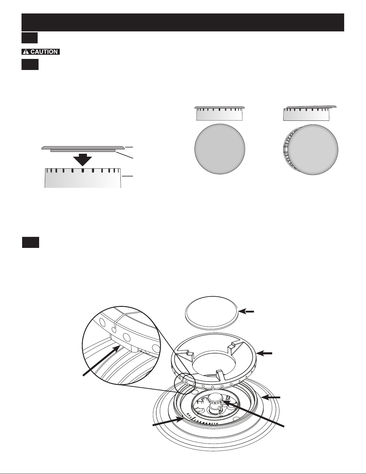
9.1
Standard Sealed Burners
Place a burner cap on each burner head, matching the cap size to the head size.
The cap for each burner has an inner locating ring which centers the cap correctly on the burner head. Make sure
each burner cap is properly aligned and level. Burners may not light or burn evenly if the burner caps are not correctly
place on the head.
Burner cap
Locating ring
Burner head
Figure 27: Burner cap assembly
9.2
Specialty Burners
Install the specialty burners as shown in Figure 29.
When the burner ring is properly seated, it will click into place. When the burner cap is properly set in place it should not
move out of the recessed area of the burner head.
To ignite properly, burner ring alignment tab must be tted into the burner base alignment tab slot. Make sure burner cap
and ring are secure before attempting to light the burner.
Correct cap placement Incorrect cap placement
Figure 28: Burner cap placement
Burner cap
Burner ring
alignment tab
Burner alignment
tab slot
Figure 29: Specialty burner assembly
Burner ring
Burner base
Simmer head
16
Page 17
30" & 36" DUAL FUEL RANGE INSTALLATION INSTRUCTIONS
9.3
Check Ignition on Surface
Burners
Operation of electric igniters should be checked after
range and supply line connectors have been carefully
checked for leaks and range has been connected to
electric power. To check for proper lighting:
1. Push in and turn a surface burner knob to the
sparking position. All electronic surface ignitors will
spark at the same time. Only the burner you are
turning on will ignite.
2. The surface burner should light once the ow of gas
reached the surface burner. Each burner should light
within four (4) seconds in normal operation after air
has been purged from supply lines. Visually check
that burner has lit.
3. Once the burner lights, the control knob should be
rotated out of the LITE position.
Turn on each of the surface burners and check to see
that they light properly and that the ames are even.
Adjust settings if necessary.
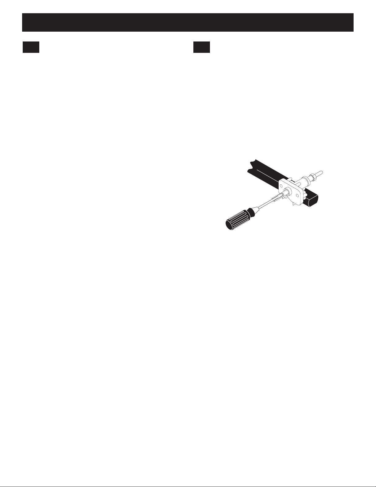
9.4
Adjust Low Settings on Surface
Burners
To adjust the low setting of surface burners:
1. Push in and turn control to LITE until burner ignites.
2. Quickly turn knob to LOWEST POSITION.
3. If burner goes out, reset control to OFF.
4. Remove the surface burner control knob and
decorative ring.
5. Insert a thin-bladed screwdriver into the hollow valve
stem and engage the slotted screw inside. Flame size
can be increased or decreased by turning the screw.
Figure 30: Turn to adjust surface ame
6. Adjust ame until you can quickly turn knob from the
sparking position to the lowest ame position without
extinguishing the ame. Flame should be as small as
possible without going out.
Notes:
• Air mixture adjustment is not required on surface
burners.
• Some models have two ames on each burner. The
center ame on these burners is not adjustable.
17
Page 18

30" & 36" DUAL FUEL RANGE INSTALLATION INSTRUCTIONS
Check Oven Operation
10
Refer to the Use and Care Guide packaged with the
range for operating instructions and for care and
cleaning of your range.
Remove all packaging from the oven before testing.
The oven is equipped with an electronic oven control.
Each of the functions has been factory checked before
shipping. However, it is suggested that you verify the
operation of the electronic oven controls once more.
Refer to the Owner's Guide for operation. Follow the
instructions for the Clock, Timer, Bake, Broil, Convection,
and Clean functions.
Bake–After setting the oven to 350°F (177°C) for baking,
the oor of the oven cavity should become warm.
Broil–When the oven is set to BROIL, the upper element
in the oven should become red.
Clean–When the oven is set for a self-cleaning cycle,
the upper element should become red during the preheat
portion of the cycle. After reaching the self-cleaning
temperature, the oor of the oven cavity should become
hot.
Convection–When the oven is set to CONV. BAKE/
ROAST at 350°F (177°C), both elements cycle on and
off alternately and the convection fan will turn. The
convection fan will stop turning when the oven door is
opened during convection baking or roasting.
After Installation
11
When All Hookups are Complete
Make sure all controls are left in the OFF position.
Model and Serial Number Location
The serial plate is located on top of the range's lower
front panel, and can be clearly viewed when the door is
open. When ordering parts for or making inquiries about
your range, have the model and serial numbers ready.
(Figure 31).
Figure 31: Model, serial number location
Before You Call for Service
Read the Avoid Service Checklist and operating
instructions in your Owner's Guide. It may save you time
and expense. The list includes common occurrences that
are not the result of defective workmanship or materials
in this appliance.
Refer to the warranty and service information in your
Owner's Guide for our phone number and address.
Please call or write if you have inquiries about your
range product and/or need to order parts.
18
Page 19

INSTRUCCIONES DE INSTALACIÓN DE ESTUFA DE COMBUSTIBLE
ADVERTENCIA
INSTRUCCIONES DE INSTALACIÓN
DUAL DE 30" Y 36"
ESTUFA DE COMBUSTIBLE DUAL DE 30" Y 36"
LA INSTALACIÓN Y SERVICIO DEBERÁN SER REALIZADOS POR UN INSTALADOR
CUALIFICADO.
IMPORTANTE: GUARDE ESTE DOCUMENTO PARA USO DEL INSPECTOR ELÉCTRICO.
LEA Y GUARDE ESTAS INSTRUCCIONES PARA FUTURAS CONSULTAS.
Canadá
POR SU SEGURIDAD: No guarde ni use gasolina
ni otros vapores o líquidos inamables cerca de éste o de
cualquier otro aparato.
Contenido
Instrucciones importantes para la seguridad ...........20-22
Dimensiones del producto ............................................ 23
Dimensiones del armario .............................................. 24
Construcción del armario.............................................. 25
Requisitos eléctricos..................................................... 25
Cable de la fuente de alimentación .............................. 26
Requisitos del suministro de combustible .................... 27
Conecte el suministro de combustible .......................... 28
Instale las rejillas de horno ...................................... 29-30
Nivele la estufa ............................................................. 31
Instale el soporte antivuelco .................................... 32-33
Instale los conjuntos de quemador ..........................34-35
Compruebe el funcionamiento del horno...................... 36
Después de la instalación............................................. 36
Ubicación de la placa de serie
(número de modelo y de serie)..................................... 36
Notas importantes para el instalador
1. Lea todas las instrucciones contenidas en estas
instrucciones de instalación antes de instalar la estufa.
2. Retire todos los materiales de embalaje del horno
y de los compartimentos de cajón antes de conectar
el suministro eléctrico a la estufa.
3. Deberá instalarse el soporte antivuelco suministrado
con el aparato.
4. Observe toda la normativa vigente.
5. Asegúrese de entregar estas instrucciones
al consumidor.
Impreso en Estados Unidos
Nota importante para el consumidor
1. Conserve estas instrucciones con la guía del
propietario para futuras consultas.
2. Al utilizar cualquier aparato que genere calor hay
algunas precauciones que deberá seguir. Estas
precauciones se detallan en su manual de uso
y cuidados. Lea atentamente su manual.
3. Asegúrese de que su dispositivo sea instalado
yconectadoatierraporuninstaladorcualicado
o técnico de servicio.
P/N 809018701 (1611) Rev.A
English – pages 1-18
Español – pages 19-36
Français – pages 37-55
19
Page 20

INSTRUCCIONES DE INSTALACIÓN DE ESTUFA DE COMBUSTIBLE
ADVERTENCIA
ADVERTENCIA
ATENCIÓN
DUAL DE 30" Y 36"
INSTRUCCIONES DE SEGURIDAD IMPORTANTES
Este dispositivo deberá ser instalado, conectado a tierra y sujeto a tareas de servicio por un instalador
o técnico de servicio cualicado.
Este manual contiene instrucciones y símbolos importantes para su seguridad. Por lo que se recomienda prestar atención
a los símbolos y seguir todas las instrucciones indicadas en el mismo. No trate de instalar ni hacer funcionar su producto
antes de leer las precauciones de seguridad de este manual. Las indicaciones de seguridad en este manual llevan un
símbolo de ADVERTENCIA o PRECAUCIÓN en función del tipo de riesgo.
Las advertencias e instrucciones importantes que aparecen en esta guía no pretenden cubrir todas las situaciones posibles
que pueden producirse. Utilice el sentido común, la precaución y el cuidado al instalar, mantener o hacer funcionar su producto.
Este es el símbolo de alerta de seguridad. Se usa para alertar sobre peligros potenciales de lesiones personales.
Obedezca todos los mensajes de seguridad que tengan este símbolo para evitar posibles lesiones o la muerte.
Indica una situación potencialmente peligrosa que, si no se evita, podría causar lesiones graves
o la muerte.
Indica una situación potencialmente peligrosa que, si no se evita, podría causar lesiones personales
leves o moderadas.
IMPORTANTE: Indica información importante, de instalación, de funcionamiento o de mantenimiento que no está
relacionada con situaciones de peligro.
WARNING:
Riesgo de volcamiento
• Un niño o adulto puede volcar la estufa y
acabar muerto.
• Verifique que se haya instalado el
dispositivo antivuelco en el piso o en la
pared.
• Asegúrese de que el dispositivo antivuelco se haya reacoplado
cuando mueva la estufa sobre el piso o a la pared.
• No utilice la estufa sin el dispositivo antivuelco instalado y
acoplado.
• Si no se siguen estas instrucciones, se puede provocar la muerte
o quemaduras graves en niños y adultos.
Tornillo
nivelador de
la estufa
Para verificar si el soporte antivuelco está instalado
correctamente, sostenga el borde trasero de la parte
trasera de la estufa usando ambos brazos. Intente inclinar
la estufa hacia adelante con cuidado. Si está instalada
correctamente, la estufa no debería inclinarse hacia
adelante.
Consulte las instrucciones de instalación del soporte
antivuelco proporcionadas con la estufa para instalarlo
adecuadamente.
Soporte
antivuelco
ADVERTENCIA
Si no se sigue exactamente
la información contenida en este manual
podría ocurrir un incendio o explosión
causando daños materiales, lesiones o muerte.
POR SU SEGURIDAD:
—No almacene ni utilice gasolina ni
otros vapores o líquidos inflamables
cerca de este o algún otro electrodoméstico.
—QUÉ HACER SI HUELE A GAS:
• No encienda ningún electrodoméstico.
• No toque ningún interruptor eléctrico;
no utilice ningún teléfono de la casa.
• Llame inmediatamente a la empresa
de suministro de gas desde el teléfono
de un vecino. Siga las instrucciones de
la empresa de suministro.
• Si no puede ponerse en contacto con
la empresa de suministro de gas, llame
a los bomberos.
—Las operaciones de instalación y servicio
técnico debe realizarlas un instalador
o proveedor de servicios cualificado
o la empresa suministradora de gas.
20
Page 21

INSTRUCCIONES DE INSTALACIÓN DE ESTUFA DE COMBUSTIBLE
ADVERTENCIA
DUAL DE 30" Y 36"
• Las temperaturas bajas pueden dañar el control
electrónico. Cuando use el electrodoméstico por primera
• Peligro de peso excesivo: Son necesarias dos
o más personas para mover e instalar la estufa.
No seguir esta instrucción puede provocar lesiones
de espalda o de otro tipo.
• Almacenamiento dentro o sobre el
electrodoméstico: No deben almacenarse
materialesinamablesenelinteriordeunhorno
o microonda, cerca de los elementos o resistencias
delasupercienienelcajóndealmacenamiento
o del calentador (en su caso). Esto incluye artículos
de papel, plástico y tela, tales como libros de cocina,
objetos de plástico y toallas, así como líquidos
inamables.Noguardeexplosivos,comolatasde
productos en aerosol, sobre o cerca del aparato.
• No deje a los niños solos y desatendidos:
Los niños deben estar siempre acompañados
y atendidos por un adulto cuando haya un
electrodoméstico en uso. Nunca permita que los
niños se sienten o se paren sobre ninguna pieza
del electrodoméstico, incluyendo el cajón de
almacenamiento, el cajón asador inferior, el cajón
calentador o el horno doble inferior.
• No guarde artículos que les interesen a los niños en los
armarios situados sobre el aparato ni en el protector
trasero. Si los niños se suben al aparato para alcanzar
dichos artículos podrían sufrir lesiones graves.
• Pararse, apoyarse o sentarse en la puerta o los
cajones de este aparato puede causar lesiones
graves y además dañar el electrodoméstico.
• No utilice el horno ni el cajón calentador
(en su caso) para guardar objetos.
• No utilice nunca este dispositivo como calentador
ambiental para calentar la sala. Esto podría tener
comoconsecuenciaenvenenamientopormonóxido
de carbono y sobrecalentamiento del aparato.
• No guarde ni use gasolina ni otros vapores o líquidos
inamablescercadeésteodecualquierotroaparato.
• No se utilizarán usar cortinas de aire ni cualquier otra
campana de ventilación superior que sople aire hacia
abajo sobre la estufa o cubierta en conjunción con
cubiertas o estufas de gas a menos que la campana
de ventilación, la estufa y la cubierta hayan sido
diseñadas,probadasycerticadasporunlaboratorio
de pruebas independiente para usarse de forma
combinada.
INSTRUCCIONES IMPORTANTES PARA
DESEMPACADO E INSTALACIÓN
Lea y siga las siguientes instrucciones y precauciones
a la hora de desempacar, instalar y realizar el
mantenimiento del electrodoméstico:
• Destruya la caja de cartón y las bolsas de plástico
después de desempacar el producto. Nunca deje que
los niños jueguen con el material de empaque. No quite
la etiqueta de cableado ni otra información adherida al
dispositivo. No quite la placa de número de modelo/serie.
21
vez, o cuando este no se haya usado por un período
largo de tiempo, asegúrese de que la unidad esté en
temperaturas superiores a los 32 °F (0 °C) durante al
menos 3 horas antes de encenderla.
• Nuncamodiqueoalterelaconstruccióndeldispositivo
retirando patas de nivelación, paneles, cubiertas de
cables y abrazaderas antivuelco/tornillos u otras partes
del dispositivo.
• Instalación correcta—Asegúrese de que su dispositivo
sea instalado y conectado a tierra por un técnico
cualicado.EnEstadosUnidos,instaleelproducto
de conformidad con el National Fuel Gas Code ANSI
Z223.1/NPFA No. 54, última edición y el National
Electrical Code NFPA No. 70 última edición y cumpla
todos los códigos eléctricos locales. En Canadá, este
artefacto debe instalarse según CAN/CGA B149.1
y CAN/CGA B149.2 y la norma CSA Standard C22.1,
Código Canadiense de Electricidad (Canadian
Electrical Code), Parte 1, y los códigos eléctricos
locales.Instaleelartefactosiguiendoexclusivamente
las instrucciones de instalación proporcionadas en la
documentación de este dispositivo.
• La instalación de dispositivos diseñados para
su instalación en hogares prefabricados (móviles)
debe ser conforme a la norma Manufactured Home
Construction and Safety Standard, título 24CFR,
parte 3280 [antes Federal Standard for Mobile Home
Construction and Safety, título 24, HUD (parte 280)] o,
si dicha norma no es aplicable, la norma Standard for
Manufactured Home Installation 1982 (Manufactured
Home Sites, Communities and Setups), ANSI Z225.1/
NFPA 501A-última versión, o los códigos locales en
Estados Unidos y CAN/CSA-Z240 MH en Canadá.
• Antes de instalar la estufa en un área con suelo
de linóleo u otro recubrimiento sintético, asegúrese
de que el recubrimiento del suelo pueda soportar
temperaturas de al menos 90°F (32,2°C) por encima
de la temperatura ambiente sin encoger, deformarse
o decolorarse. No instale la estufa sobre moqueta sin
colocar una lámina de madera contrachapada de ¼"
(0,64 cm) de grosor entre la estufa y la moqueta.
• Asegúrese de que el recubrimiento de las paredes y los
materiales de los armarios que rodean la estufa puedan
soportar el calor generado por el aparato.
• Para eliminar riesgo de quemaduras o incendio por
contactoconlasunidadesdelasuperciecaliente,deberá
evitarse el espacio de almacenamiento en armarios sobre
lasupercie.Siesnecesariodisponerdealmacenamiento
en armarios, es posible reducir el riesgo instalando una
campana de estufa que que se proyecte horizontalmente
al menos 5 pulgadas más allá de la parte inferior del armario.
• No obstruya la circulación de aire en el respiradero
del horno, alrededor de la base o bajo el panel frontal
inferior del aparato. Este dispositivo necesita aire
fresco para funcionar correctamente.
• Asegúresedequehayaunextintordeespuma
adecuado disponible, ubicado de manera visible
y fácilmente accesible cerca del electrodoméstico.
Page 22

INSTRUCCIONES DE INSTALACIÓN DE ESTUFA DE COMBUSTIBLE
ADVERTENCIA
DUAL DE 30" Y 36"
INSTRUCCIONES ESPECIALES PARA
ELECTRODOMÉSTICOS INSTALADOS
EN EL ESTADO DE MASSACHUSETTS
Este electrodoméstico solo puede ser instalado en el
Estado de Massachusetts por un fontanero o instalador
de gas con licencia de Massachusetts. Al utilizar un
conectordegasexible,nodeberásuperarlos3pies
(36 pulgadas) de longitud. Deberá instalarse una
válvula manual de gas con manija tipo "T" en la línea
de suministro de gas al dispositivo.
CONVERSIÓN A GAS LP
Este electrodoméstico permite la conversión a gas de
petróleo licuado (LP).
Si la conversión a gas licuado
no es realizada por un instalador o un electricista
calicadoexistenriesgosdelesionespersonales
o la muerte por choque eléctrico. Las adiciones, cambios
o conversiones necesarios para que esta estufa cumpla
satisfactoriamente con sus requisitos de funcionamiento
deben ser realizados por un técnico de servicio.
INSTRUCCIONES IMPORTANTES PARA SERVICIO
Y MANTENIMIENTO
• No repare ni cambie ninguna pieza del aparato que
noestéespecícamenteindicadaenlosmanuales.
Todas las restantes tareas de servicio deberán ser
realizadasexclusivamenteporuntécnicocualicado.
Esto reduce el riesgo de lesiones personales y daños
en el aparato.
• Póngase siempre en contacto con su distribuidor,
concesionario, agente de servicio o fabricante en
relación con cualquier problema o circunstancia que
no comprenda.
• Pida a su distribuidor que le recomiende un técnico
cualicadoyunserviciodereparaciónautorizado.
Aprenda a desconectar la corriente del aparato y el
disyuntor o caja de fusibles en caso de emergencia.
• Retire la puerta del horno no utilizado que vaya a tirar
o guardar.
• No toque la bombilla de luz del horno caliente con
un paño húmedo. Esto podría provocar la rotura
de la bombilla. Manipule las bombillas halógenas
(en su caso) con un paño de papel o guantes suaves.
Desconecte el aparato o apague la alimentación del
aparato antes de quitar y cambiar la bombilla.
Si necesita realizar una conversión a gas LP,
llame a su distribuidor local de gas LP para obtener
asistencia. El kit de conversión a gas LP se incluye con
este electrodoméstico y se encuentra en el panel inferior
trasero (parte trasera) de la estufa. Antes de instalar el
kit, asegúrese de leer atentamente las instrucciones de
instalación de LP y seguirlas cuidadosamente al realizar
la instalación.
22
Page 23

INSTRUCCIONES DE INSTALACIÓN DE ESTUFA DE COMBUSTIBLE
ADVERTENCIA
DUAL DE 30" Y 36"
Dimensiones del producto
No instale la unidad en el armario antes de leer las dos páginas siguientes.
D
C
B
A
E
Figura 1: Dimensiones del producto
C. FONDO EN EL
MODELO A. ALTO B. ANCHO
30"
36" 35 7/8" (91,1 cm) 48 3/8" (122,9 cm)
41 5/8" (105,7 cm) Mín.
425/8"(108,3cm)Máx.
29 7/8" (75,9 cm)
FRONTAL DE LA
ESTUFA
27 1/2" (69,9cm)
D. ALTURA DE LA
CUBIERTA
35 3/4" (90,8 cm) MÍn.
363/4"(93,3cm)Máx.
E. FONDO CON
LA PUERTA
ABIERTA
46 1/4" (117,5 cm)
23
Page 24

INSTRUCCIONES DE INSTALACIÓN DE ESTUFA DE COMBUSTIBLE
DUAL DE 30" Y 36"
Dimensiones del armario
Separaciones y dimensiones
• Dejeunaseparaciónadecuadaentreelelectrodomésticoylassuperciescombustiblesadyacentes.
• Ubicación: compruebe la ubicación en la que se instalará el electrodoméstico. Compruebe que la
alimentación eléctrica y la estabilidad del suelo sean adecuadas.
• Deberán utilizarse las dimensiones indicadas. Las dimensiones indicadas ofrecen una separación mínima.
Lasuperciedecontactodeberásersólidaynivelada.
J
H
G
I
F
Figura 2: Dimensiones del armario
13"Máx.
(33cmMáx.)
18" Mín.
(45,7 cm Mín.)
24" Mín.
(61 cm Mín.)
24½"Máx.
(62,2cmMáx.)
F. ANCHO
MODELO
30"
36"
NOTAS:
1. No selle la estufa a los armarios laterales.
2. Separacióndelasparedesadyacentesuotrassuperciesoestructurasverticales,comoarmarios.
3. Las mediciones indicadas son la separación mínima entre la cubierta y la parte inferior del armario.
4. 0"deseparaciónentrelaestufaylosarmariososuperciesverticalespordebajodelaalturadelacubierta.
5. 0" de separación entre la parte posterior de la estufa y la pared o armario.
MÍNIMO DEL
RECORTE
30 1/16"
(76,4 cm)
36 1/16"
(91,6 cm)
G. ALTURA DEL
MOSTRADOR
36" (91,4 cm) Estándar
35 3/4" (90,8 cm) Mín.
H. SEPARACIÓN
DESDE LAS
PAREDES
LATERALES
5" (12,7 cm) Mín. 30" (76,2 cm) Mín. 30" (76,2 cm) Mín.
7" (17,8 cm) Mín. 36" (91,4 cm) Mín. 36" (91,4 cm) Mín.
24
2
I. SEPARACIÓN
DESDE LA
CUBIERTA Y LA
PARTE INFERIOR
DEL ARMARIO
J. ANCHO DE
SEPARACIÓN DE
LOS ARMARIOS
3
SUPERIORES
Page 25

INSTRUCCIONES DE INSTALACIÓN DE ESTUFA DE COMBUSTIBLE
ADVERTENCIA
ATENCIÓN
correspondientes a su tipo de instalación
DUAL DE 30" Y 36"
1
Construcción del armario
Para eliminar riesgo de quemaduras
o incendio por contacto con las unidades de la
superciecaliente,nodejeespaciodealmacenamiento
en armarios sobre la estufa. Si hay espacio de
almacenamiento en armarios sobre la estufa, reduzca
el riesgo instalando una campana de estufa que que se
proyecte horizontalmente al menos 5 pulgadas /12,7 cm)
más allá de la parte inferior del armario.
Línea central
de la estufa
Siga las instrucciones
Figura 3: Construcción del armario
1.1
Instalación: Armario a ambos lados
1. Si la estufa va a instalarse con armario a ambos
lados, dibuje una linea central en el suelo entre los
armarios (Figura 5).
2. Si la parte posterior de la estufa no queda al nivel de
la pared (la ubicación de la toma de corriente puede
no permitir que la estufa se coloque contra la pared),
dibuje una línea en el suelo donde estará el borde
posterior de la estufa.
3. Instale soportes antivuelco (ver "Instalación del
soporte antivuelco").
1.2
Instalación: Armario solo a un lado
1. Si va a instalar la estufa con armario solo a un lado,
muevalaestufaasuposiciónnal.
2. Dibuje una línea en el suelo por el lateral de la estufa
que no queda junto al armario. Si la parte posterior
de la estufa no queda al nivel de la pared (la ubicación
de la toma de corriente puede no permitir que la estufa
se coloque contra la pared), dibuje una línea en el
suelo donde estará el borde posterior de la estufa.
3. Instale soportes antivuelco (ver "Instalación del
soporte antivuelco").
1.3
Instalación: Sin armario
1. Si la estufa no va a instalarse junto a un armario,
muevalaestufaasuposiciónnal.
2. Haga una marca en el suelo a ambos lados de la
estufa. Si la parte posterior de la estufa no queda
al nivel de la pared (la ubicación de la toma de
corriente puede no permitir que la estufa se coloque
25
contra la pared), dibuje una línea en el suelo donde
estará el borde posterior de la estufa.
3. Instale soportes antivuelco (ver "Instalación del
soporte antivuelco").
2
Requisitos eléctricos
Peligro de descarga eléctrica –Este aparato precisa
conexiónatierra.Utilicesoloelcabledealimentación
suministradoconelelectrodoméstico.Unaconexión
o toma de tierra inadecuada puede provocar descargas
eléctricas, daños en el electrodoméstico, lesiones
personales, fuego o la muerte.
Requisitos de puesta a tierra
Este dispositivo deberá ser instalado y conectado a tierra
poruntécnicodeserviciocualicado.
En Estados Unidos, instale el producto de conformidad
con el National Fuel Gas Code ANSI Z223.1/NPFA No. 54,
última edición y el National Electrical Code NFPA No. 70
última edición y cumpla todos los códigos eléctricos locales.
En Canadá, este artefacto debe instalarse según CAN/
CGA B149.1 y CAN/CGA B149.2 y la norma CSA Standard
C22.1, Código Canadiense de Electricidad (Canadian
Electrical Code), Parte 1, y los códigos eléctricos locales.
Para su seguridad personal, este electrodoméstico debe
estardebidamentepuestoatierra.Paraunamáxima
seguridad, el cable de alimentación debe estar enchufado
a un tomacorriente del voltaje adecuado, que esté
correctamente polarizado y debidamente puesto a tierra
de acuerdo con los códigos locales. Es responsabilidad
personal del consumidor hacer que un electricista
calicadoinstaleuntomacorrienteadecuadoconun
receptáculo de pared debidamente puesto a tierra.
Este dispositivo está previsto para conectarse a un
tomacorriente estándar 14-50R.
Tomacorriente eléctrico
Se requiere para todas las
instalaciones
Tomacorriente de cuatro
cables (14-50R)
Si solo se dispone de corriente eléctrica CA de 4 cables
monofásica de 240 voltios y 60 Hz, este dispositivo
necesitará protección de circuitos con fusibles de un
mínimo de 40 amperios en ambos lados del cable.
Se recomienda un disyuntor o fusible de retardo.
Asegúrese de que el tomacorriente esté al alcance de la
ubicaciónnaldelaparato.
No pellizque el cable de alimentación eléctrica entre
la estufa y la pared.
Page 26

INSTRUCCIONES DE INSTALACIÓN DE ESTUFA DE COMBUSTIBLE
12”
(30,5 cm)
8”
(20,3 cm)
ADVERTENCIA
dentro de la zona sombreada
de la estufa
de la estufa
DUAL DE 30" Y 36"
Cable de la fuente de alimentación
3
Ubicaciones recomendadas para
la instalación de tomacorrientes
La ubicación sugerida para la tomacorriente se muestra
en la Figura 4 para modelos de 30" y en la Figura 5
para modelos de 36". La toma también puede estar en
la esquina inferior izquierda del armario adyacente a la
derecha, según se muestra en la Figura 6
Línea
central
de la estufa
10"
(25,4 cm)
PARED
7" Máx.
(17,8 cm Máx.)
Busque el conector eléctrico
en la zona sombreada
Figura 4: Ubicación de la toma en modelos de 30"
SUELO
Línea
central
Peligro de descarga eléctrica –No trate de instalar
el dispositivo directamente a una caja de empalme,
modicarelcableinstaladodefábricaniconectar
al aparato un cable de alimentación distinto. Si la
tomadecorrientenoessucienteparasoportarlos
requisitos de este electrodoméstico, es responsabilidad
del consumidor solicitar la instalación de una toma
adecuada por un electricista. Una instalación
oconexióneléctricainadecuadapuedeprovocar
descargas eléctricas, daños en el electrodoméstico,
lesiones personales, fuego o la muerte.
Este dispositivo está equipado con un cable de fuente
de alimentación de cuatro hilos conectado de fábrica
(Figura 7). Este cable tiene una capacidad nominal de
240 voltios, 40 amperios y una temperatura nominal de
194°F (90°C). Este cable está homologado por UL/CSA
y ha sido comprobado y autorizado para su uso con este
dispositivo.
Línea
central de
la estufa
14"
(35,6 cm)
(1 cm Máx.)2.7
5" Máx.
PARED
SUELO
Busque el conector eléctrico
Línea
central
Figura 5: Ubicación de la toma en modelos de 36"
Figura 7: Cable de alimentación eléctrica conectado
de fábrica
Potencia nominal del
electrodoméstico*
120/240
Voltios
120/208
Voltios
Potencia nominal de la
fuente de alimentación
Amperios
1-10 kW 0-7.6 kW 30
8,8-16,5 kW 7,8-12,5 kW 40 o 50
16,6-22,5 kW 12,6-18,5 kW 50
* La carga NEC calculada es inferior a la carga
conectada total indicada en la placa del número de serie.
Figura 6: Ubicación de la toma en el armario adyacente
26
Page 27

INSTRUCCIONES DE INSTALACIÓN DE ESTUFA DE COMBUSTIBLE
ADVERTENCIA
al dispositiv
s
Posición abierta
)
DUAL DE 30" Y 36"
Requisitos del suministro
4
de combustible
Esta unidad está diseñada para operar con columna
de agua de 4"(10,16 cm) con presión de colector de gas
natural de (1,0 kPa).
Un regulador de presión convertible se conecta al
colector de la estufa y DEBERÁ estar conectado en
serie con la línea de suministro de gas. El regulador está
ubicado según se muestra en la Figura 8 y es accesible
desde la parte inferior de la estufa.
del lado derecho es la ubicación ideal para la válvula
principal de cierre, si la estufa se instaló dentro del
espacio de almacenamiento del armario.
4.2
Válvula de cierre
La línea de suministro deberá estar equipada con una
válvula de cierre homologada según se muestra en
la Figura 10. Esta válvula deberá estar ubicada en la
misma habitación que la estufa y deberá estar en una
ubicación que facilite su apertura y cierre. No bloquee el
acceso a la válvula de cierre. La válvula sirve para abrir
o cerrar el gas que llega al aparato.
o
a la tubería de
suministro de ga
Paraunadecuadofuncionamiento,lapresiónmáxima
de entrada al regulador deberá ser no superior a 14"
(35,56 cm) de columna de presión de agua (3,5 kPa).
La presión de entrada del regulador deberá ser al menos
1" (0,25 kPa) mayor que el ajuste de presión del colector
regulador. El regulador está ajustado para columna de
agua de 4" (10,16 cm) de presión de colector de gas
natural (1,0 kPa); la presión de entrada deberá ser al
menos de columna de agua de 5" (12,60 cm) de gas
natural (1,25 kPa).
Para funcionar a 2000 pies sobre el nivel del mar, el ajuste
nominal del aparato se reduce en un 4 por ciento cada
1000 pies adicionales.
4.1
Los tubos de suministro de gas se encuentran en
la pared lateral del armario de la derecha. El armario
Figura 9: Ubicación recomendada del suministro de gas
Modelos de 30"
Figura 8: Ubicaciones del regulador
Modelos de 36"
Ubicación del suministro de gas
8”
(20,3 cm
12”
(30,5 cm)
Válvula de cierre
Figura 10: Válvula de cierre
El suministro de gas entre la válvula de cierre y el
regulador puede estar conectado mediante tubo rígido
omediantetuberíametálicaexibleconectadamediante
uniones con homologación A.G.A./C.G.A. cuando los
códigos locales permitan su uso.
El usuario deberá conocer la ubicación de la válvula
principal de cierre y tener fácil acceso a ella.
4.3
Conversión a gas de petróleo licuado
(L.P.) Gas.
Este electrodoméstico permite la conversión a petróleo
licuado (LP). Gas.
Si la conversión a gas licuado
no es realizada por un instalador o un electricista
calicadoexistenriesgosdelesionespersonalesola
muerte por choque eléctrico. Las adiciones, cambios
o conversiones necesarios para que esta estufa cumpla
satisfactoriamente con sus requisitos de funcionamiento
deben ser realizados por un técnico de servicio.
Si necesita realizar una conversión a gas LP, llame
a su distribuidor local de gas L.P. para obtener
asistencia. El kit de conversión a gas LP se incluye con
este electrodoméstico y se encuentra en el panel inferior
trasero (parte trasera) de la estufa. Antes de instalar el
kit, asegúrese de leer atentamente las instrucciones de
instalación de L.P. y seguirlas cuidadosamente al realizar
la instalación.
Para LP/gas propano, el regulador deberá estar ajustado
para columna de agua de 10" (25,4 cm) de presión de
colector (2,5 kPa); la presión de entrada deberá ser al
menos de columna de agua de 11" (27,9 cm) (2,75 kPa).
27
Page 28

INSTRUCCIONES DE INSTALACIÓN DE ESTUFA DE COMBUSTIBLE
ADVERTENCIA
ATENCIÓN
Válvula de
cierre
manual
Unión
abocinada
Unión
abocinada
FLUJO DEL
GAS
Regulador
de presión
Apagado
Racor
Racor
Conector
flexible
Acceso
Tapa
Encendido
ADVERTENCIA
DUAL DE 30" Y 36"
Conecte el suministro
5
de combustible
5.1
Conexión del suministro de combustible
Este dispositivo deberá ser instalado,
conectado a tierra y sujeto a tareas de servicio por un
instaladorotécnicodeserviciocualicado.
Noaprietedemasiadolasconexiones.
Elreguladoresdevaciado.Apretarexcesivamentepuede
crear grietas en el regulador, lo que puede suponer
pérdidadegasypotencialmentefuegooexplosión.
Este aparato incluye un regulador. La línea de suministro
de gas precisa las siguientes piezas que no se
suministran con el aparato:
• Válvula de cierre manual
• Racores de 1/2" (2)
• Adaptador de unión abocinada de 1/2" (2)
• Conectorexible
La línea de suministro de gas a la válvula de cierre deberá
ser de tubo sólido de 1/2" (1,27 cm) o 3/4" (1,9 cm).
Instale el tubo de suministro de gas al regulador de
presión en el orden indicado en la Figura 11. Todas las
conexionesdeberánapretarseconllaveinglesa.
5.2
Comprobar si hay pérdidas
No utilice llama para comprobar
sihaypérdidasenlasconexionesdegas.Comprobar
laexistenciadepérdidasconllamapuedeprovocar
fuegooexplosión.
Después de conectar la estufa al suministro de gas,
compruebe si hay pérdidas en el sistema con un
manómetro. Si no dispone de manómetro, abra el
suministro de gas y utilice un detector de pérdidas de
líquidos(oaguayjabón)entodaslasjuntasyconexiones
para comprobar si hay pérdidas. Las pérdidas se indicarán
mediantelaaparicióndeburbujasenlasconexiones
o juntas.
Deberán sellarse todas las aperturas en la pared o suelo
donde esté instalada la estufa.
1. Aprietetodaslasconexionessiesnecesariopara
evitar la pérdida de gas en la estufa o línea de
suministro.
2. Desconecte esta estufa y su válvula de cierre
individual del sistema de tuberías de suministro de
gas durante las pruebas de comprobación del sistema
a presiones de prueba superiores a 1/2 psig (columna
de agua de 3,5 kPa o 14" (35,56 cm)).
3. Aísle la estufa del sistema de tuberías de suministro
de gas cerrando la válvula manual de cierre individual
durante las pruebas del sistema de tuberías de suministro
de gas a presiones iguales o inferiores a 1/2 psig
(columna de agua de 3,5 kPa o 14" (35,56 cm)).
Alutilizarconductodegasexibleenlaestufa,déjelo
losucientementeojocomoparasacarlaestufafuera
del recorte para tareas de limpieza o servicio.
Utilice un compuesto para juntas de tubería para uso
con gas natural y LP/propano para sellar todas las
conexionesdegas.Siseutilizanconectoresexibles,
asegúrese de que los conectores no dañados.
Nopermitaqueelconductoexiblequedepinzadoentre
la pared y la estufa.
Figura 11: Flujo de conexión del suministro
de combustible
28
Page 29

INSTRUCCIONES DE INSTALACIÓN DE ESTUFA DE COMBUSTIBLE
DUAL DE 30" Y 36"
Instale las rejillas de horno
6
6.1
Modelos de 30" - Soportes de rejilla
en escalera
Para ayudar en la instalación de los soportes de rejillas
de horno de porcelana, aplique una ligera capa de aceite
decocinaratodoslosextremosdelossoportessegúnse
muestra en la Figura 12.
Figura 14: Soportes de rejilla de escalera - extremos
inferiores
6.2
Modelos de 30" - Rejillas deslizantes
Las rejillas deslizantes se instalan como otras rejillas
del horno.
El tope de la rejilla deslizante (Figura 15) deberá estar
dentro del soporte de escalera para que la rejilla se deslice
Figura 12: Soportes de rejilla de escalera - áreas con
aceite
adecuadamente.
1. Mantenga el soporte de rejillas de horno con un
pequeñoánguloeinsertelosextremosenlosoricios
de la parte superior de la cavidad del horno (Figura 13).
2. Introduzcalarejillaenlosoriciossuperiores,
alineandolosextremosinferioresconlosoricios
de la parte de abajo (Figura 13).
Figura 13: Soportes de rejilla de escalera - extremos
superiores
3. Unavezcolocadoslosextremossuperiores,
mantenga el soporte de rejillas al nivel del lateral del
hornoeinsertelosextremosinferioresenlosoricios
de la parte de abajo (Figura 14).
4. Deslicelosextremosinferioresenlosoriciosdela
parte de abajo. Es posible que precise hacer algo
de fuerza para ajustar la rejilla en su sitio (Figura 14).
Figura 15: Tope de rejilla deslizante
Coloque la rejilla en los soportes de las rejillas. Incline
la parte posterior de la rejilla ligeramente hacia arriba
para que el tope quede colocado en el interior de la rejilla
de escalera. Vuelva a colocar la rejilla del horno en su
posición
Asegúrese de deslizar por completo la rejilla de modo que
la parte posterior se detenga al encontrarse con el soporte
vertical de la rejilla de escalera.
Para evitar posibles daños en el horno, no intente cerrar
la puerta del horno hasta que todas las rejillas están
completamente posicionadas dentro de la cavidad del horno.
29
Page 30

INSTRUCCIONES DE INSTALACIÓN DE ESTUFA DE COMBUSTIBLE
DUAL DE 30" Y 36"
6.3
Modelos de 36" - Soportes de rejilla
en escalera
1. Saque los tornillos de pulgar situados a cada lado
de la cavidad del horno (ver Figura 16).
Figura 18: Guías de rejilla de escalera
Las rejillas deslizantes tienen una apariencia ligeramente
distinta de las planas (ver Figura 19). Solo es posible
instalar rejillas deslizantes en las guías deslizantes.
1. Extiendatotalmentelasdosguíasinferioresfuera
del horno.
Figura 16: Tornillo de pulgar de rejilla de escalera
2. Coloque las rejillas de escalera en los soportes
situados en los laterales del horno (ver Figura 17).
3. Vuelva a colocar los tornillos quitados en el Paso 1.
2. Vuelva a colocar la rejilla deslizante sobre las guías.
3. Cerca de la parte trasera de la rejilla, ajuste la
ranura de la rejilla en las pestañas de la guía. Cerca
de la parte delantera de la rejilla, ajuste el pasador
deguíaeneloriciodelarejilla(verFigura19).
4. Una vez instalada la rejilla, puede meterse y sacarse
de la cavidad del horno en las guías deslizantes.
Repita para el conjunto de guías superiores.
Figura 17: Soportes de rejilla de escalera
6.4
Modelos de 36" - Rejillas deslizantes
En modelos de 36", las guías deslizantes de las rejillas
de horno deslizantes vienen preinstaladas en los
soportes de rejillas de escalera (ver Figura 18).
Figura 19: Instalación de las Instale las rejillas de horno
Las rejillas deslizantes solo pueden utilizarse en estas
posiciones. Las rejillas pueden sacarse de las guías
y utilizarse como rejillas planas normales en todas las
demás posiciones.
Introduzca las rejillas de horno planas normales
en cualquier posición que desee.
30
Page 31

INSTRUCCIONES DE INSTALACIÓN DE ESTUFA DE COMBUSTIBLE
DUAL DE 30" Y 36"
7
Nivele la estufa
Nivele la estufa y ajuste la altura de la cubierta antes
de la instalación en la abertura recortada (en su caso).
1. Coloque una rejilla en el centro del horno.
2. Coloque un nivel en la rejilla (Figura 20). Haga dos
lecturas con el nivel colocado diagonalmente en una
dirección y después en la otra.
3. En su caso, nivele la estufa ajustando las cuatro
patas niveladoras con una llave inglesa (Figura 21).
Base de la estufa
Pata
niveladora
Subir
Bajar
Decorativo
Tornillo de
la pata
Figura 20: Utilice las rejillas de horno para nivelar
el electrodoméstico
Figura 21: Ajuste de la altura del aparato
4. Deslice la estufa en la abertura recortada
y compruebe bien el nivel. Si la estufa no está
nivelada, saque la unidad y reajuste las patas de
nivelación o asegúrese de que el suelo esté nivelado.
31
Page 32

INSTRUCCIONES DE INSTALACIÓN DE ESTUFA DE COMBUSTIBLE
ADVERTENCIA
DUAL DE 30" Y 36"
8
Instale el soporte antivuelco
Para reducir el riesgo de vuelco
delaparato,estedebejarsealsuelomedianteelsoporte
antivuelco adecuadamente instalado con sus tornillos,
incluidos con la estufa. Estas piezas se encuentran dentro
del horno. Si no se instala el soporte antivuelco, la estufa
puedevolcarsesisesecolocaexcesivopesoenlapuerta
abierta del horno o si se sube un niño sobre ella. Pueden
producirse lesiones graves por los líquidos calientes
vertidos o por la propia estufa.
Si la estufa se mueve a una ubicación distinta, también
deben moverse los soportes antivuelco e instalarse con
la estufa.
Herramientas necesarias:
• Llave inglesa
• Trinquete
• Taladro y broca de 1/8" (0,32 cm)
• Llave de tuerca de 5/16" (0,8 cm)
• Nivel
WARNING:
Riesgo de volcamiento
• Un niño o adulto puede volcar la estufa y
acabar muerto.
• Verifique que se haya instalado el
dispositivo antivuelco en el piso o en la
pared.
• Asegúrese de que el dispositivo antivuelco se haya reacoplado
cuando mueva la estufa sobre el piso o a la pared.
• No utilice la estufa sin el dispositivo antivuelco instalado y
acoplado.
• Si no se siguen estas instrucciones, se puede provocar la muerte
o quemaduras graves en niños y adultos.
Tornillo
nivelador de
la estufa
Soporte
antivuelco
8.1
Localice el soporte utilizando la plantilla
El soporte puede estar situado a la izquierda o derecha
de la estufa. Marque el suelo o pared en la que se situará
el lado izquierdo o derecho de la estufa.
Figura 22: Plantilla del soporte
Si la parte posterior de la estufa queda contra la pared
o a menos de 1/2” (1,3 cm) de la pared una vez instalada,
puede utilizar el método de montaje en pared o suelo.
Si está instalada la moldura e impide que el soporte
quede al nivel de la pared, retire la moldura o el soporte
de montaje sobre el suelo.
Para montaje en pared, busque el soporte colocando
el borde posterior de la plantilla contra la pared posterior
y el borde lateral de la plantilla en la marca de referencia
en el lateral de la estufa. Coloque el soporte encima de
laplantillaymarquelasituacióndelosoriciosdelos
tornillos en la pared.
Si la parte posterior de la estufa queda contra la pared
o a menos de 1/2” (1,3 cm) de la pared una vez instalada,
puede utilizar el método de montaje en pared o suelo.
Para montaje sobre el suelo, localice el soporte colocando
el borde posterior de la plantilla en el lugar donde
se situará la parte posterior de la estufa.
Marquelaubicacióndelosoriciosdelostornillos
indicada en la plantilla.
Para verificar si el soporte antivuelco está instalado
correctamente, sostenga el borde trasero de la parte
trasera de la estufa usando ambos brazos. Intente inclinar
la estufa hacia adelante con cuidado. Si está instalada
correctamente, la estufa no debería inclinarse hacia
adelante.
Consulte las instrucciones de instalación del soporte
antivuelco proporcionadas con la estufa para instalarlo
adecuadamente.
32
Page 33

INSTRUCCIONES DE INSTALACIÓN DE ESTUFA DE COMBUSTIBLE
Pata niveladora
Montaje en el suelo
Soporte antivuelco
d
la coci
atras
DUAL DE 30" Y 36"
8.2
Perfore los oricios y je el soporte
Perforeunoriciopilotode1/8”dondevayanasituarselos
tornillos.
Sisevaamontarelsoporteenlapared,taladreunoricio
pilotoconunánguloaproximadode20°.Sisevaamontar
el soporte en suelos de mampostería o cerámica, taladre
unoriciopilotode3/16”(4,8mm)y1-3/4”deprofundidad.
Figura 23: Perfore oricios piloto
Los tornillos suministrados pueden utilizarse en
madera u hormigón. Utilice una llave de tuerca de 5/16”
odestornilladordecabezaplanaparajarbienelsoporte.
8.3
Compruebe el nivel y posicione la estufa
Compruebeelniveldelainstalaciónnal.Nota:Seprecisa
una separación mínima de 1/8” entre la parte inferior
de la estufa y la pata niveladora para dejar espacio para
el soporte. Utilice un nivel para comprobar los ajustes.
1/8" mínimo
Figura 24: Apretar el soporte
Montaje en pare
Placa de la
pared
Figura 25: Utilice las rejillas de horno para nivelar
el electrodoméstico
Deslice la estufa en su posición.
Lateral de
la estufa
Deslice
na
hacia
Figura 26: Deslice el aparato en el soporte.
Para controlar si la abrazadera antivuelco está montada
correctamente, utilice ambos brazos y agarre el borde
trasero de la parte posterior de la cocina. Intente
inclinar cuidadosamente hacia delante la cocina.
Si está correctamente instalada, la cocina no debería
inclinarse hacia delante.
Si la estufa se mueve a una ubicación distinta, también
deben moverse los soportes antivuelco e instalarse con
la estufa.
33
Page 34

INSTRUCCIONES DE INSTALACIÓN DE ESTUFA DE COMBUSTIBLE
ATENCIÓN
DUAL DE 30" Y 36"
9
Instale los conjuntos de quemador
Paraevitarexplosiones,utilicelacubiertacontodaslastapasdelosquemadoresadecuadamente
instaladas.
9.1
Quemadores sellados estándar
Coloque una tapa de quemador en cada cabezal de quemador, ajustando el tamaño de la tapa al del cabezal.
La tapa de cada quemador tiene una anilla interior de localización que centra la tapa correctamente sobre el cabezal
del quemador. Compruebe que todas las tapas estén adecuadamente alineadas y niveladas. Es posible que los
quemadores no se enciendan ni quemen de forma uniforme si las tapas no están correctamente colocadas sobre
el cabezal.
Tapa del
quemador
Ubicación
de la anilla
Cabeza de
quemador
Figura 27: Conjunto de tapa de quemador
Ubicación correcta
de la tapa
Figura 28: Ubicación de la tapa del quemador
Ubicación incorrecta
de la tapa
9.2
Quemadores especiales
Instale los quemadores especiales según se muestra en la Figura 29.
Cuando la anilla del quemador esté correctamente asentada hará un sonido. Cuando la tapa del quemador esté en
su posición correcta no deberá moverse del hueco del cabezal del quemador.
Para encenderse correctamente, la pestaña de alineación de la anilla del quemador deberá ajustarse en la ranura
dealineacióndelabasedelquemador.Asegúresedequelatapadelquemadorylaanillaesténjasantesdetratar
de encender el quemador.
Tapa del quemador
Anilla del quemador
Pestaña de
alineación del
quemador
Base del quemador
Ranura de la pestaña
de alineación del
quemador
Figura 29: Conjunto de quemador especial
Cabezal de fuego lento
34
Page 35

INSTRUCCIONES DE INSTALACIÓN DE ESTUFA DE COMBUSTIBLE
DUAL DE 30" Y 36"
9.3
Compruebe la ignición en los
quemadores de la supercie
Compruebe el funcionamiento de los encendedores
después de haber comprobado cuidadosamente si hay
pérdidas en los conectores de la línea de suministro
y de conectar la estufa a la corriente eléctrica. Para
comprobar el correcto encendido:
1. Presione y gire una manija de quemador de
superciehastalaposicióndechispa.Todoslos
encendedoresdesupercieelectrónicosemitirán
chispas al mismo tiempo. Solo se encenderá el
quemador que ha accionado.
2. Elquemadordelasuperciedeberáencenderseuna
vez que el gas llegue al quemador. Cada quemador
deberá encenderse al cabo de cuatro (4) segundos
en funcionamiento normal después de haberse
purgadoelairedelaslíneasdesuministro.Verique
visualmente que el quemador se haya encendido.
3. Una vez encendido el quemador, gire el mando
a una posición distinta de LITE.
Girecadaunodelosquemadoresdelasupercie
y compruebe que enciendan correctamente y que las
llamas sean uniformes. Haga los ajustes necesarios.
9.4
Utilice un nivel bajo en los
quemadores de la supercie
Para ajustar el nivel bajo de los quemadores de la
supercie:
1. Pulse y gire el control hasta LITE hasta que
se encienda el quemador.
2. Gire rápidamente el mando hasta la POSICIÓN MÁS
BAJA.
3. Si el quemador se apaga, vuelva a poner el control
en posición OFF.
4. Extraigaelmandodecontroldelquemadordela
supercieylaanilladecorativa.
5. Inserte un destornillador de punta plana en el vástago
de válvula hueco y accione el tornillo ranurado interior.
El tamaño de la llama puede aumentarse o reducirse
girando el tornillo.
Figura 30: Gire para ajustar la llama de la supercie
6. Ajuste la llama hasta que pueda girar rápidamente el
mando de la posición de chispa a la posición de llama
más baja sin que se apague la llama. La llama deberá
ser lo más baja posible sin apagarse.
Notas:-
• No se precisa ajuste de la mezcla de aire en los
quemadoresdelasupercie.
• Algunos modelos tienen dos llamas en cada quemador.
La llama central de estos quemadores no es ajustable.
35
Page 36

INSTRUCCIONES DE INSTALACIÓN DE ESTUFA DE COMBUSTIBLE
DUAL DE 30" Y 36"
Compruebe el funcionamiento
10
del horno
Consulte la guía de uso y cuidados incluida con la
estufa para ver las instrucciones de funcionamiento
y de cuidado y limpieza de su estufa.
Retire todo el empacado del horno antes de hacer las
pruebas.
El horno cuenta con control electrónico. Todas las
funciones se han comprobado en fábrica antes de
entregarse.Sinembargo,esrecomendablevericaruna
vez más el funcionamiento de los controles electrónicos
del horno. Consulte la guía del propietario. Siga las
instrucciones de las funciones de reloj, temporizador,
horneado, asado, confección y limpieza.
Bake (Hornear)–Después de ajustar el horno a 350°F
(177°C) para hornear, el piso de la cavidad del horno
deberá calentarse.
Broil (Asar)–Cuando el horno se ajusta a BROIL,
el elemento superior del horno deberá ponerse rojo.
Clean (Limpiar)–Cuando el horno se ajusta a un ciclo
de autolimpieza, el elemento superior deberá ponerse
rojo durante la parte de precalentamiento del ciclo.
Al alcanzar la temperatura de autolimpieza, el piso
de la cavidad del horno deberá calentarse.
Convección–Cuando el horno se ajusta a CONV.
BAKE/ROAST a 350°F (177°C), ambos elementos
se encienden y apagan alternativamente y el ventilador
de convección gira. El ventilador de convección deja
de girar al abrir la puerta del horno durante el horneado
o asado con convección.
Después de la instalación
11
Cuando se han completado todas las conexiones
Asegúrese de que todos los controles queden
en posición OFF (Apagado).
Ubicación del número de modelo y serie
La placa del número de serie se encuentra en la parte
superior del panel frontal inferior de la estufa y puede
verse claramente al abrir la puerta. Al hacer pedido
de piezas o consultas sobre su estufa, tenga a mano
el número de modelo y serie. (Figura 31).
Figura 31: Ubicación del número de modelo y serie
Antes de solicitar asistencia
Lea la Lista de comprobación para evitar llamadas de
servicio y las instrucciones de funcionamiento de su
Guía del propietario. Puede ahorrarle tiempo y dinero.
La lista incluye circunstancias habituales que no se
deben a defectos de mano de obra o materiales en
el aparato.
Consulte la información sobre garantía y servicio en su
Guía del propietario, donde encontrará nuestro número
de teléfono y dirección. Llame o escriba si tiene alguna
duda sobre su producto y para hacer pedido de piezas.
36
Page 37

CUISINIÈRE BI-ÉNERGIE 30 po & 36 po INSTRUCTIONS D'INSTALLATION
INSTRUCTIONS D'INSTALLATION
CUISINIÈRE BI-ÉNERGIE 30 po & 36 po
L'INSTALLATION ET LE SERVICE DOIVENT ÊTRE EFFECTUÉS PAR
UN INSTALLATEUR QUALIFIÉ.
IMPORTANT : CONSERVER POUR L'INSPECTEUR EN ÉLECTRICITÉ LOCAL.
LIRE ET CONSERVER CES INSTRUCTIONS POUR CONSULTATION ULTÉRIEURE.
Canada
POUR VOTRE SÉCURITÉ : Ne pas entreposer ou
utiliser de la gazoline ou autres vapeurs et liquides inammables à
proximité de cet ou tout autre appareil.
Table des matières
Consignes de sécurité importantes ......................... 38-40
Dimensions du produit .................................................. 41
Dimensions de la carrosserie ....................................... 42
Construction de la carrosserie ...................................... 43
Exigences électriques..............................................43-44
Cordon d'alimentation ................................................... 44
Exigences d'alimentation en combustion ..................... 45
Remarques importantes pour l'installateur
1. Lire toutes les instructions contenues dans ces
instructions d'installation avant d'installer la cuisinière.
2. Enlever tout le matériel d'emballage de la cuisinière
et des compartiments tiroirs avant de connecter
l'alimentation électrique à la cuisinière.
3. Le support antibasculement fourni avec l'appareil
ménager doit être installé.
4. Observer tous les codes et règlements applicables.
5. S'assurer de laisser ces instructions avec
le consommateur.
Connecter l'alimentation en combustion ....................... 46
Installer les grilles du four ........................................47-48
Mettre la cuisinière de niveau ....................................... 49
Installer le support antibasculement ........................ 50-51
Installer les assemblages de brûleur ....................... 52-53
Vérier le fonctionnement du four................................. 54
Après l'installation ......................................................... 54
Emplacement de la plaque de série
(Numéro de modèle & de série) ................................... 54
Remarque importante pour le consommateur
1. Conserver ces instructions avec votre guide
du propriétaire pour consultation ultérieure.
2. Lors de l'utilisation d'appareils qui génèrent de la
chaleur, il y a des consignes de sécurité que vous
devez respecter. Ces consignes sont expliquées dans
votre manuel Utilisation et Entretien. Lire attentivement
votre manuel.
3. S'assurer que votre appareil ménager est installé
et mis à la terre par un installateur qualié ou par
un technicien de service.
Imprimé aux États-Unis
N/P 809018701 (1611) Rév.A
English – pages 1-18
Español – pages 19-36
Français – pages 37-54
37
Page 38

CUISINIÈRE BI-ÉNERGIE 30 po & 36 po INSTRUCTIONS D'INSTALLATION
n'est pas suivie exactement, un incendie ou une
CONSIGNES DE SÉCURITÉ IMPORTANTES
Cet appareil doit être installé, mis à la terre et entretenu par un installateur qualié ou par
un technicien de service.
Ce manuel contient des symboles et des instructions de sécurité importants. Veuillez porter attention à ces symboles
et suivre toutes les instructions données. Ne pas tenter d'installer ou de faire fonctionner votre appareil avant d'avoir
lu les consignes de sécurité dans ce manuel. Les points de sécurité à travers ce manuel sont étiquetés avec un énoncé
d'AVERTISSEMENT ou de PRUDENCE selon le type de risque.
Les avertissements et les instructions importantes qui apparaissent dans ce guide ne sont pas destinées à couvrir
toutes les conditions et situations possibles qui peuvent se produire. Il faut faire preuve de bons sens, de prudence
et de précaution lors de l'installation, de l'entretien et du fonctionnement de votre appareil.
Ceci est le symbole d'alerte de sécurité. Il est utilisé pour vous alerter des risques de blessures corporelles potentielles.
Se conformer à tous les messages de sécurité qui suivent ce symbole an d'éviter des blessures corporelles ou la mort.
Indique une situation potentiellement dangereuse qui, si non évitée, peut causer la mort ou des
blessures graves.
Indique une situation potentiellement dangereuse qui, si non évitée, peut causer des blessures mineures ou
modérées.
IMPORTANT : Indique des informations sur l'installation, le fonctionnement, l'entretien ou des informations utiles qui
ne sont pas reliées à un risque.
Risque de basculement
• Un enfant ou un adulte peut faire
basculer la cuisinière et en décéder.
• Assurez-vous d’enclencher le dispositif anti-renversement
lorsque la cuisinière est déplacée sur le plancher ou contre le
mur.
• Ne faites pas fonctionner la cuisinière si le dispositif anti-renversement n’est pas en place et enclenché.
• Le non-respect de ces instructions peut causer des blessures
fatales ou de graves brûlures aux enfants et aux adultes.
Pour vérifier si le support anti-renversement est correctement installé,
attrapez le bord arrière de la cuisinière à deux mains. et essayez
doucement de faire basculer la cuisinière vers l’avant. Lorsque le
support est correctement installé, la cuisinière ne doit pas basculer
vers l’avant.
Reportez-vous aux instructions d’installation du support anti-renversement fournies avec la cuisinière pour vous assurer que
l’installation est effectuée de façon appropriée.
• Vérifiez que le dispositif anti-renversement a été fixé au plancher ou au mur.
Pied de mise à
niveau de la
cuisinière
Support antirenversement
AVERTISSEMENT
Si l'information dans ce manuel
explosion peut causer des dommages matériels,
des blessures corporelles ou la mort.
POUR VOTRE SÉCURITÉ :
— Ne pas entreposer ou utiliser de la gazoline
ou autres vapeurs ou liquides inflammables
à proximité de cet ou tout autre appareil.
— QUE FAIRE SI VOUS SENTEZ DU GAZ :
• Ne pas tenter d'allumer aucun appareil.
• Ne pas toucher à aucun interrupteur
électrique; ne pas utiliser aucun
téléphone dans votre immeuble.
• Appeler immédiatement votre fournisseur
de gaz à partir du téléphone d'un voisin.
Suivre les instructions du fournisseur de gaz.
• Si vous ne pouvez pas joindre votre
fournisseur de gaz, appeler le service
d'incendie.
— L'installation et le service doivent être
effectués par un installateur qualifié,
un préposé à l'entretien ou le
fournisseur de gaz.
38
Page 39

CUISINIÈRE BI-ÉNERGIE 30 po & 36 po INSTRUCTIONS D'INSTALLATION
• Les températures froides peuvent endommager
la commande électronique. Lors de l'utilisation de cet
• Risque de poids excessif--Utiliser deux
personnes ou plus pour déplacer et installer
la cuisinière. Ne pas suivre ces instructions peut
causer des blessures au dos ou autres blessures.
• Rangement dans ou sur l'appareil—Les matières
inammables ne devraient pas être rangées dans
un four ou micro-onde, près des brûleurs de
surface ou éléments, ou dans le tiroir de rangement
ou réchaud (si équipé). Ceci inclut le papier,
le plastique, et les articles en tissu, comme des
livres de cuisine, des articles en plastique, et des
serviettes, de même que des liquides inammables.
Ne pas ranger des explosifs, comme des diffuseurs
d'aérosol, sur ou près de l'appareil.
• Ne pas laisser les enfants seuls - Les enfants
ne devraient pas être laissés seuls ou sans
surveillance dans la zone où l'appareil est en
utilisation. Ils ne devraient jamais pouvoir s'asseoir
ou se tenir debout sur aucune partie de l'appareil,
incluant le tiroir de rangement, le tiroir du gril
inférieur, le tiroir réchaud, ou le four double inférieur.
• Ne pas ranger d'articles qui pourraient intéresser les
enfants dans les armoires au-dessus de l'appareil
ou sur les dosserets des cuisinières. Les enfants qui
grimpent sur ou près de l'appareil pour atteindre des
articles pourraient être blessés gravement.
• Se tenir debout, se pencher ou s'asseoir sur
la porte ou les tiroirs de cet appareil peut causer
des blessures graves et aussi causer des
dommages à l'appareil.
• Ne pas utiliser le four ou le tiroir réchaud
(si équipé) pour du rangement.
• Ne jamais utiliser votre appareil comme chaufferette
pour chauffer ou réchauffer la pièce. Le faire
peut causer un empoisonnement au monoxyde
de carbone et une surchauffe de l'appareil.
• Ne pas entreposer ou utiliser de la gazoline
ou autres vapeurs et liquides inammables
à proximité de cet ou tout autre appareil.
• Un rideau d'air ou autres hottes de cuisinière qui
fonctionnent en soufant un débit d'air vers le bas
dans une cuisinière ou surface de cuisson, ne devra
pas être utilisé conjointement avec les cuisinières
au gaz ou les surfaces de cuisson autres que
lorsque la cuisinière ou la surface de cuisson a été
conçue, testée, listée par un laboratoire de test
indépendant pour être utilisé l'un avec l'autre.
INSTRUCTIONS IMPORTANTES POUR
LE DÉSEMBALLAGE ET L'INSTALLATION
Lire et suivre les instructions et les consignes ci-dessous pour
le désemballage, l'installation et l'entretien de votre appareil:
• Détruire le carton et les sacs de plastique après avoir
désemballé l'appareil. Ne jamais laisser les enfants jouer
avec le matériel d'emballage. Ne pas enlever l'étiquette
de câblage et autre littérature attachées à l'appareil.
Ne pas enlever la plaque du numéro de modèle/de série.
39
appareil pour la première fois, ou lorsque l'appareil
n'a pas été utilisé pour une longue période de temps,
s'assurer que l'appareil a été dans des températures
au-dessus de 32 °F (0 °C) pendant au moins 3 heures
avant de mettre l'appareil en marche.
• Ne jamais modier ou altérer la construction de
l'appareil en enlevant les pieds de mise à niveau,
les panneaux, les couvre-ls, les supports/vis
antibasculement, ou toute autre pièce de l'appareil.
• Installation appropriée - S'assurer que votre appareil est
installé et mis à la terre correctement par un technicien
qualié. Aux États-Unis, installer en conformité avec
le National Fuel Gas Code ANSI Z223.1/NPFA No. 54,
édition la plus récente et le National Electrical Code
NFPA No. 70 édition la plus récente, et les exigences
du code d'électricité local. Au Canada, installer en
conformité avec la CAN/CGA B149.2 et CSA Standard
C22.1, Code canadien de l'électricité, Partie 1- éditions
les plus récentes et les exigences du code d'électricité
local. Installer uniquement selon les instructions
d'installation fournie dans l'emballage de littérature pour
cet appareil.
• L'installation d'appareils conçus pour être installés dans
une maison préfabriquée (mobile) doit être conforme
à la norme Manufactured Home Construction and
Safety Standard, title 24CFR, part 3280 [Anciennement
le Federal Standard for Mobile Home Construction
and Safety, title 24, HUD (part 280)] ou lorsqu'un telle
norme n'est pas applicable, la norme Standard for
Manufactured Home Installation 1982 (Manufactured
Home Sites, Communities and Setups), ANSI Z225.1/
NFPA 501A-édition la plus récente, ou les codes locaux
aux États-Unis et avec la norme CAN/CSA-Z240 MH au
Canada.
• Avant d'installer la cuisinière dans un endroit recouvert
avec du linoléum ou autre recouvrement de plancher
synthétique, s'assurer que le recouvrement de plancher
peut tolérer au moins 90 °F (32,2 °C) au-dessus de la
température de la pièce sans rétrécir, se déformer ou
se décolorer. Ne pas installer la cuisinière sur du tapis
à moins de placer une plaque isolante ou une feuille de
contreplaqué d'une épaisseur de 1/4 po (0,64 cm) entre
la cuisinière et le tapis.
• S'assurer que le revêtement mural et les matériaux
des armoires autour de la cuisinière peuvent résister
à la chaleur générée par l'appareil.
• Pour éliminer le risque de brûlures ou d'incendie
en accédant au-dessus des unités à surface chaude,
l'espace de rangement dans les armoires au dessus
de la surface de l'unité devrait être évité. Si le rangement
dans les armoires est permis, le risque peut être diminué
en installant une hotte qui dépasse horizontalement
un minimum de 5 pouces au-delà du bas de l'armoire.
• Ne pas obstruer le débit d'air au niveau de l'évent
du four, autour de la base, ou sous le panneau avant
inférieur de l'appareil. Cet appareil requiert de l'air frais
pour fonctionner adéquatement.
• S'assurer d'avoir un extincteur à mousse disponible,
visible, facilement accessible et situé près de l'appareil.
Page 40

CUISINIÈRE BI-ÉNERGIE 30 po & 36 po INSTRUCTIONS D'INSTALLATION
INSTRUCTIONS SPÉCIALES POUR LES APPAREILS
INSTALLÉS DANS L'ÉTAT DU MASSACHUSETTS
Cet appareil peut être installé uniquement dans l'État du
Massachusetts par un plombier autorisé ou un monteur
d'installations au gaz. Si un connecteur de gaz exible
est utilisé, il ne doit pas excéder 3 pieds (36 pouces) de
longueur. Une soupape à gaz manuelle de type poignée
en « T » doit être installée dans l'alimentation en gaz vers
cet appareil.
CONVERSION AU GAZ PL
Cet appareil permet une conversion au Gaz de pétrole
liquéé (PL).
Des blessures corporelles ou la mort
suite à un choc électrique peuvent se produire si la
conversion au gaz PL n'est pas faite par un installateur
qualié ou un électricien. Tous les ajouts, changements
ou conversions requis an que cet appareil satisfasse
les besoins de l'application doivent être effectués par
un technicien qualié.
Si une conversion PL est requise, communiquer avec
votre fournisseur de gaz PL pour de l'assistance.
La trousse de conversion PL est fournie avec cet
appareil et est située sur le panneau ARRIÈRE inférieur
(côté arrière) de la cuisinière. Avant d'installer la trousse,
s'assurer de lire les Instructions d'installation PL et les
suivre méticuleusement lors de l'installation.
INSTRUCTIONS IMPORTANTES POUR LE SERVICE
ET L'ENTRETIEN
• Ne pas réparer ou remplacer aucune pièce
de l'appareil à moins que spéciquement
recommandé dans les manuels. Tout autre entretien
devrait être effectué uniquement par un technicien
qualié. Ceci réduit le risque de blessures corporelles
et de dommages à l'appareil.
• Toujours communiquer avec votre détaillant,
distributeur, agent de service, ou fabricant au
sujet de problèmes ou de conditions que vous
ne comprenez pas.
• Demander à votre détaillant de recommander
un technicien qualié et un service de réparation
autorisé. Savoir comment déconnecter l'alimentation
à l'appareil au niveau du disjoncteur ou de la boîte
à fusibles en cas d'urgence.
• Enlever la porte du four de tout four non utilisé s'il doit
être entreposé ou jeté.
• Ne pas toucher à une ampoule de four chaude avec
un linge humide. Le faire pourrait causer un bri de
l'ampoule. Manipuler les lampes halogènes (si équipé)
avec des essuie-tout ou des gants doux. Déconnecter
l'appareil ou couper l'alimentation vers l'appareil avant
d'enlever ou de remplacer l'ampoule.
40
Page 41

CUISINIÈRE BI-ÉNERGIE 30 po & 36 po INSTRUCTIONS D'INSTALLATION
Dimensions du produit
Ne pas installer l'unité dans la carrosserie avant d'avoir lu les deux prochaines pages.
D
C
B
A
Figure 1 : Dimensions du produit
MODÈLE A. HAUTEUR B. LARGEUR
30"
36" 35 7/8 po (91,1 cm)
41 5/8 po (105,7 cm)
Min.
42 5/8 po (108,3 cm)
Max.
29 7/8 po (75,9 cm)
C. PROFONDEUR
JUSQU'À L'AVANT
DE LA CUISINIÈRE
27 1/2 po (69,9cm)
E
D. HAUTEUR DE
LA SURFACE DE
CUISSON
35 3/4 po (90,8 cm)
Min.
36 3/4 po (93,3 cm)
Max.
E. PROFONDEUR
AVEC PORTE
OUVERTE
46 1/4 po
(117,5 cm)
48 3/8 po
(122,9 cm)
41
Page 42

CUISINIÈRE BI-ÉNERGIE 30 po & 36 po INSTRUCTIONS D'INSTALLATION
Dimensions de la carrosserie
Dégagements et dimensions
• S'assurer d'avoir des dégagements adéquats entre l'appareil et les surfaces combustibles adjacentes.
• Emplacement - Vérier l'emplacement où l'appareil sera installé. S'assurer que l'alimentation électrique
est appropriée et que le plancher est stable.
• Les dimensions illustrées doivent être utilisées. Les dimensions données offrent un dégagement minimal.
La surface de contact doit être solide et de niveau.
J
H
G
I
F
Figure 2 : Dimensions de la carrosserie
13 po Max.
(33 cm Max.)
18 po Min.
(45,7 cm Min.)
24 po Min.
(61 cm Min.)
24½ po Max.
(62,2 cm Max.)
F. LARGEUR
MODÈLE
30"
36"
REMARQUES :
1. Ne pas sceller la cuisinière aux armoires sur les côtés.
2. Dégagement des murs adjacents ou autres surfaces ou structures verticales comme les armoires.
3. Les mesures listées sont des dégagements minimaux entre la surface de cuisson et le bas de l'armoire.
4. Dégagement de 0 po entre la cuisinière et les armoires ou les surfaces verticales qui sont sous la hauteur de la surface de cuisson.
5. Dégagement de 0 po entre l'arrière de la cuisinière et le mur arrière ou l'armoire.
MINIMALE DE
DÉCOUPE
30 1/16 po
(76,4 cm)
36 1/16 po
(91,6 cm)
G. HAUTEUR DU
COMPTOIR
36 po (91,4 cm)
Standard
35 3/4 po (90,8 cm)
Min.
H. DÉGAGEMENT
DES MURS
LATÉRAUX
5 po (12,7 cm) Min. 30 po (76,2 cm) Min. 30 po (76,2 cm) Min.
7 po (17,8 cm) Min. 36 po (91,4 cm) Min. 36 po (91,4 cm) Min.
42
2
I. DÉGAGEMENT
DE LA SURFACE DE
CUISSON AU BAS
DE L'ARMOIRE
3
J. LARGEUR DE
DÉGAGEMENT
DES ARMOIRES
AU-DESSUS
Page 43

CUISINIÈRE BI-ÉNERGIE 30 po & 36 po INSTRUCTIONS D'INSTALLATION
le type d'installation que vous avez
1
Construction de la carrosserie
Pour éliminer le risque de brûlures ou
d'incendie en accédant au-dessus des unités à surface
chaude, ne pas avoir d'espace de rangement dans les
armoires au dessus de la cuisinière. S'il y a un espace de
rangement dans les armoires au-dessus de la cuisinière,
réduire le risque en installant une hotte qui dépasse
horizontalement un minimum de 5 po (12,7 cm) au-delà
du bas de l'armoire.
Ligne centrale
de la cuisinière
Suivre les instructions pour
Figure 3 : Construction de la carrosserie
1.1
Installation : Armoire des deux côtés
1. Si la cuisinière sera installée avec une armoire des
deux côtés, tracer une ligne centrale sur le plancher
entre les armoires (Figure 5).
2. Si l'arrière de la cuisinière ne sera pas collée au mur
(l'emplacement de la prise peut ne pas permettre à la
cuisinière d'être positionnée contre le mur), tracer une
ligne sur le plancher où l'arrière de la cuisinière arrivera.
3. Installer les supports antibasculement (voir « Installer
le support antibasculement »).
1.2
Installation : Armoire sur un côté
seulement
1. Si la cuisinière sera installée avec une armoire sur un
côté seulement, déplacer la cuisinière en position nale.
2. Tracer une ligne sur le plancher le long du côté de
la cuisinière qui n'est pas contre l'armoire. Si l'arrière de
la cuisinière ne sera pas collée au mur (l'emplacement
de la prise peut ne pas permettre à la cuisinière
d'être positionnée contre le mur), tracer une ligne
sur le plancher où l'arrière de la cuisinière arrivera.
3. Installer les supports antibasculement (voir « Installer
le support antibasculement »).
1.3
Installation : Sans armoire
1. Si la cuisinière ne sera installée contre une armoire,
déplacer la cuisinière en position nale.
2. Tracer sur le plancher le long des deux côtés de la
cuisinière. Si l'arrière de la cuisinière ne sera pas collée
au mur (l'emplacement de la prise peut ne pas permettre
à la cuisinière d'être positionnée contre le mur), tracer une
ligne sur le plancher où l'arrière de la cuisinière arrivera.
3. Installer les supports antibasculement
(voir « Installer le support antibasculement »).
2
Exigences électriques
Risque de choc électrique -Une mise à la terre électrique
est requise sur cet appareil. Utiliser uniquement le cordon
d'alimentation fourni avec cet appareil. Des connexions et
une mise à la terre inadéquates peuvent causer un choc
électrique, des dommages à l'appareil, des blessures
corporelles, un incendie ou la mort.
Exigences de mise à la terre
Cet appareil doit être installé et mis à la terre et entretenu par
un technicien qualié.
Aux États-Unis, installer en conformité avec le National
Fuel Gas Code ANSI Z223.1/NPFA No. 54, édition la plus
récente et le National Electrical Code NFPA No. 70 édition
la plus récente, et les exigences du code d'électricité local.
Au Canada, installer en conformité avec la CAN/CGA B149.2
et CSA Standard C22.1, Code canadien de l'électricité,
Partie 1- éditions les plus récentes et les exigences du code
d'électricité local.
Pour votre sécurité personnelle, cet appareil doit être
adéquatement mis à la terre. Pour une sécurité maximale,
le cordon d'alimentation doit être branché dans une prise
électrique de tension adéquate, qui est correctement
polarisée et adéquatement mise à la terre en conformité
avec les codes locaux. Le consommateur a la responsabilité
personnelle d'avoir la prise appropriée avec la prise de
courant murale adéquate et correctement mise à la terre
installée par un électricien qualié.
Cet appareil est conçu pour être branché dans une prise
de courant murale standard 14-50R.
Prise de courant murale
Requise pour toutes les
installations
Prise à 4 ls (14-50R)
Lorsque seulement une alimentation électrique CA, 4 ls,
monophasée, 240 volt, 60 Hz est disponible, cet appareil
requiert une protection de circuit minimale de 40 amp avec
fusible des deux côtés de la ligne.
Un disjoncteur ou fusible temporisé est recommandé.
S'assurer que la prise de courant murale est à portée
de main de l'emplacement nal d'installation de l'appareil.
Ne pas coincer le cordon d'alimentation entre la cuisinière
et le mur.
43
Page 44

CUISINIÈRE BI-ÉNERGIE 30 po & 36 po INSTRUCTIONS D'INSTALLATION
12”
(30,5 cm)
8”
(20,3 cm)
Repérer le branchement électrique
Zone intérieure ombragée
Ligne centrale
de la cuisinière
14"
(35,6 cm)
PLANCHER
MU
R
Ligne centrale
de la cuisinière
5 po Max.
(1
cm Max.)
2,7
de la cuisinière
de la zone ombragée
Cordon d'alimentation
3
Emplacements recommandés pour
l'installation de la prise murale
L'emplacement suggéré de la prise murale est illustré
dans la Figure 4 pour les modèles de 30 po et dans la
Figure 5 pour les modèles de 36 po. La prise peut aussi
être située dans le coin inférieur gauche de l'armoire
adjacente de droite, tel qu'illustré dans la Figure 6.
Ligne centrale
de la cuisinière
10"
(25,4 cm)
MUR
Risque de choc électrique -Ne pas tenter d'installer
l'appareil directement à une boîte de jonction,
de modier le cordon installé en usine, ou de connecter
un cordon d'alimentation différent à l'appareil. Si la
prise murale n'est pas sufsante pour supporter les
exigences de cet appareil, il est de la responsabilité
du consommateur d'avoir la prise appropriée installée
par un électricien. Une installation et des connexions
électriques inadéquates peuvent causer un choc
électrique, des dommages à l'appareil, des blessures
corporelles, un incendie ou la mort.
7 po Max.
(17,8 cm Max.)
PLANCHER
Repérer le branchement
électrique à l'intérieur
Ligne centrale
Figure 4 : Emplacement de la prise Modèles 30 po
Figure 5 : Emplacement de la prise Modèles 36 po
Cet appareil ménager est équipé d'un cordon
d'alimentation 4 ls, connecté en usine (Figure 7).
Ce cordon est conçu pour 240 volts, 40 amps, et une
température nominale de 194 °F (90 °C). Ce cordon est
en conformité avec UL/CSA et a été testé et approuvé
pour être utilisé avec cet appareil ménager.
Figure 7 : Cordon d'alimentation connecté en usine
Caractéristiques
nominales de
l'appareil*
120/240
Volts
120/208
Volts
Caractéristiques
nominales de
l'alimentation
Amps
1-10 kW 0-7.6 kW 30
8,8-16,5 kW 7,8-12,5 kW 40 ou 50
16,6-22,5 kW 12,6-18,5 kW 50
* La charge NEC calculée est moins que la charge
connectée totale listée sur la plaque de série.
Figure 6 : Emplacement de la prise armoire adjacente
44
Page 45

Position Ouvert
ver
s ligne d'alimentation de gaz
12”
(30.5 cm)
8“
(20.3 cm)
CUISINIÈRE BI-ÉNERGIE 30 po & 36 po INSTRUCTIONS D'INSTALLATION
Exigences d'alimentation
4
en combustion
Cet appareil est conçu pour fonctionner à une pression
d'admission de gaz naturel de 4 po (10,16 cm) de
colonne d'eau (1,0 kPa).
Un régulateur de pression convertible est connecté
au manifold de la cuisinière et DOIT être connecté en
série avec la ligne d'alimentation de gaz. Le régulateur
est situé tel qu'illustré sur la Figure 8 et est accessible
à partir de l'avant de la cuisinière.
Modèles 30 po Modèles 36 po
Figure 8 : Emplacements du régulateur
Pour un fonctionnement approprié, la pression d'admission
maximale au régulateur devrait être pas plus que 14 po
(35,56 cm) de pression de colonne d'eau (3,5 kPa).
La pression d'admission au régulateur doit être au
moins 1 po (0,25 kPa) plus grande que le réglage de la
pression d'admission du régulateur. Le régulateur est
réglé pour une pression d'admission de gaz naturel de
4 po (10,16 cm) de colonne d'eau (1,0 kPa), la pression
d'admission doit être au moins 5 po (12,60 cm) de
colonne d'eau (1,25 kPa) gaz naturel.
Pour un fonctionnement à 2 000 pi. au dessus du niveau
de la mer, les caractéristiques nominales sont réduites de
4 pourcent pour chaque 1 000 pi. supplémentaire.
4.1
Emplacement de l'alimentation en gaz
La tuyauterie de l'alimentation en gaz peut être à travers
le mur latéral de l'armoire de droite. L'armoire du côté
Figure 9 : Emplacement d'alimentation de gaz
recommandé
droit est un emplacement idéal pour le robinet d'arrêt
principal, si la cuisinière est installée en dedans de
l'espace de rangement de l'armoire.
4.2
Robinet d'arrêt
La ligne d'alimentation devrait être équipée d'un robinet
d'arrêt approuvé tel qu'illustré dans la Figure 10.
Ce robinet devrait être situé dans la même pièce que
la cuisinière et devrait être dans un emplacement qui
permet une ouverture et une fermeture faciles. Ne pas
bloquer l'accès au robinet d'arrêt. Le robinet sert à ouvrir
ou à fermer le gaz vers l'appareil.
s appareil
ver
Robinet d'arrêt -
Figure 10 : Robinet d'arrêt
L'alimentation de gaz entre le robinet d'arrêt et le
régulateur peut être connectée par un tuyau rigide ou par
un tuyau avec raccord union métallique exible approuvé
A.G.A./C.G.A là où les codes locaux le permettent.
L'utilisateur doit connaître l'emplacement du robinet
d'arrêt principal et avoir un accès facile à celui-ci.
4.3
Conversion au Gaz de pétrole
liquéé (PL).
Cet appareil permet une conversion au Gaz de pétrole
liquéé (PL).
Des blessures corporelles ou la mort
suite à un choc électrique peuvent se produire si la
conversion au gaz PL n'est pas faite par un installateur
qualié ou un électricien. Tous les ajouts, changements
ou conversions requis an que cet appareil satisfasse
les besoins de l'application doivent être effectués par un
technicien qualié.
Si une conversion PL est requise, communiquer avec
votre fournisseur de gaz PL pour de l'assistance.
La trousse de conversion PL est fournie avec cet
appareil et est située sur le panneau ARRIÈRE inférieur
(côté arrière) de la cuisinière. Avant d'installer la trousse,
s'assurer de lire les Instructions d'installation PL et les
suivre méticuleusement lors de l'installation.
Pour le gaz PL/Propane, le régulateur doit être réglé pour
une pression d'admission de 10 po (25,4 cm) de colonne
d'eau (2,5 kPa), la pression d'admission doit être au
moins 11 po (27,9 cm) de colonne d'eau (2,75 kPa).
45
Page 46

CUISINIÈRE BI-ÉNERGIE 30 po & 36 po INSTRUCTIONS D'INSTALLATION
Robinet
d'arrêt
manuel
Raccord
évasé
DÉBIT DE GAZ
Raccord
évasé
Régulateur
de pression
Marche
(On)
Mamelon
Arrêt (Off)
Connecteur
flexible
Mamelon
Accès
Couvercle
Connecter l'alimentation
5
en combustion
5.1
Connexion de l'alimentation
en combustion
Cet appareil doit être installé, mis à la
terre et entretenu par un installateur qualié ou par un
technicien de service.
Ne pas trop serrer les connexions.
Le régulateur est moulé sous pression. Trop serrer peut
faire craquer le régulateur ce qui causerait une fuite de
gaz et un possible incendie ou explosion.
Cet appareil inclut un régulateur. La ligne d'alimentation
en gaz requiert les pièces suivantes qui ne sont pas
fournies avec l'appareil.
• Robinet d'arrêt manuel
• Mamelon 1/2 po (2)
• Adaptateur de raccord évasé 1/2 po (2)
• Connecteur exible
La ligne d'alimentation en gaz vers le robinet d'arrêt
devrait être un tuyau non perforé de 1/2 po (1,27 cm)
ou 3/4 po (1,9 cm).
Installer le tuyau d'alimentation en gaz au régulateur de
pression dans l'ordre décrit dans la Figure 11. Toutes les
connexions devraient être serrées avec une clé.
5.2
Vérication des fuites
Ne pas utiliser une amme pour vérier
les fuites des connexions de gaz. Vérier les fuites avec
une amme peut causer un incendie ou une explosion.
Après avoir connecté la cuisinière à l'alimentation en gaz,
vérier le système pour la présence de fuites avec un
manomètre. Si un manomètre n'est pas disponible, ouvrir
l'alimentation en gaz et utiliser un détecteur de fuite liquide
(ou du savon et de l'eau) sur tous les joints et connexions
pour vérier la présence de fuites. Les fuites seront
indiquées par des bulles qui apparaissent au niveau des
connexions ou des joints.
Toutes les ouvertures dans le mur ou le plancher
où la cuisinière sera installée doivent être scellées.
1. Serrer toutes les connexions si nécessaire an
d'empêcher une fuite de gaz dans la surface de
cuisson ou la ligne d'alimentation.
2. Déconnecter cette cuisinière et son robinet d'arrêt
individuel du système de tuyauterie d'alimentation
en gaz durant tout test de pression du système à des
pressions de test supérieures à 1/2 psig (3,5 kPa
ou 14 po (35,56 cm) de colonne d'eau).
3. Isoler la cuisinière du système de tuyauterie
d'alimentation en gaz en fermant son robinet d'arrêt
individuel durant tout test de pression du système
de tuyauterie d'alimentation en gaz à des pressions
de test égales à ou inférieures à 1/2 psig (3,5 kPa
ou 14 po (35,56 cm) de colonne d'eau).
Figure 11 : Connexion d'écoulement de l'alimentation
en combustion
Lorsqu'un conduit de gaz exible est utilisé sur
la cuisinière, laisser sufsamment de lâche pour
tirer la cuisinière à l'extérieur de la découpe pour
le nettoyage et le service.
Utiliser de la pâte à joint prévue pour être utilisée avec
le gaz naturel et PL/Propane pour sceller toutes les
connexions de gaz. Si des connecteurs exibles sont
utilisés, s'assurer que les connecteurs ne sont pas
entortillés.
Ne pas laisser le conduit exible se pincer entre le mur
et la cuisinière.
46
Page 47

CUISINIÈRE BI-ÉNERGIE 30 po & 36 po INSTRUCTIONS D'INSTALLATION
Installer les grilles du four
6
6.1
Modèles 30 po - Supports latéraux de
grilles
Pour faciliter l'installation des supports de grilles du
four en porcelaine, appliquer une mince couche d'huile
à cuisson à toutes les dents des supports tel qu'illustré
dans la Figure 12.
Figure 14 : Supports latéraux de grille- dents
inférieures
6.2
Modèles 30 po - Grilles coulissantes
Les grilles coulissantes s'installent comme les autres
grilles du four.
L'arrêt de la grille coulissante (Figure 15) doit être
à l'intérieur du support latéral pour que la grille entre
Figure 12 : Supports latéraux de grille- zones de huilage
1. Tenir le support de grille du four à un léger angle et
insérer les dents dans les trous sur le dessus de la
cavité du four (Figure 13).
2. Soulever la grille dans les trous supérieurs, en alignant
les dents inférieures avec les trous inférieurs (Figure 13).
et sorte adéquatement.
Figure 13 : Supports latéraux de grille- dents
supérieures
3. Une fois les dents supérieures en place, tenir le
support de grille du four à égalité avec le côté du four
et insérer les dents inférieures dans les trous inférieurs
(Figure 14).
4. Glisser les dents inférieures vers le bas dans les trous
inférieurs. Une certaine force peut être requise pour
mettre la grille en place (Figure 14).
Figure 15 : Arrêt de la grille coulissante
Placer la grille du four sur les supports de grille. Incliner
l'arrière de la grille légèrement vers le haut pour mettre
l'arrêt en place à l'intérieur du support latéral. Remettre
la grille du four en place.
S'assurer de glisser la grille complètement de sorte que
l'arrière de la grille arrête en atteignant le support vertical
de la grille latérale.
Pour empêcher tout dommage possible au four, ne pas
tenter de fermer la porte du four jusqu'à ce que toutes
les grilles du four soient positionnées complètement
à l'intérieur de la cavité du four.
47
Page 48

CUISINIÈRE BI-ÉNERGIE 30 po & 36 po INSTRUCTIONS D'INSTALLATION
6.3
Modèles 36 po - Supports latéraux
de grilles
1. Enlever les vis à serrage à main situées de chaque
côté de la cavité du four (voir Figure 16).
Figure 18 : Glisseurs Grille latérale
Les grilles coulissantes apparaissent un peu différentes
que les grilles plates (voir Figure 19). Seulement les
grilles coulissantes peuvent être installées sur les rails
de glissement.
1. Étendre complètement les deux glisseurs du bas
hors du four.
Figure 16 : Vis à serrage à main Grille latérale
2. Placer les grilles latérales dans les crochets de
support situés sur les côtés du four (voir Figure 17).
2. Placer la grille coulissante sur les glisseurs.
3. Près de l'arrière de la grille, mettre la fente de grille
dans les onglets du rail. Près de l'avant de la grille,
mettre la goupille de grille dans le trou sur le rail
(voir Figure 19).
4. Une fois la grille installée, elle peut être sortie
ou entrée dans la cavité du four sur les rails de
glissement. Répéter pour les glisseurs du haut.
Figure 17 : Supports Grille latérale
3. Remettre les vis enlevées dans l'Étape 1.
6.4
Modèles 36 po - Grilles coulissantes
Sur les modèles 36 po, les rails de glissement pour les
grilles coulissantes du four sont préinstallées sur les
supports de grille latéraux (voir Figure 18).
Figure 19 : Installer les grilles coulissantes
Les grilles coulissantes ne peuvent être utilisées que
dans ces positions. Les grilles peuvent être enlevées
des rails et utilisées comme une grille plate régulière
sur toutes les autres positions de grille.
Insérer les grilles plates régulières du four dans toute
position désirée.
48
Page 49

CUISINIÈRE BI-ÉNERGIE 30 po & 36 po INSTRUCTIONS D'INSTALLATION
7
Mettre la cuisinière de niveau
Mettre de niveau la cuisinière et dénir la hauteur
de la surface de cuisson avant l'installation dans
l'ouverture découpée (si applicable).
1. Installer une grille de four dans le centre du four.
2. Placer un niveau sur la grille (Figure 20). Prendre
2 lectures avec le niveau placé diagonalement
dans une direction puis dans l'autre.
3. Mettre à niveau la cuisinière, si nécessaire,
en ajustant les 4 pieds de mise à niveau avec
une clé (Figure 21).
Base de la cuisinière
Figure 20 : Utiliser les grilles du four pour mettre
l'appareil de niveau
Pied de mise
à niveau
Soulever
Abaisser
Figure 21 : Ajuster la hauteur de l'appareil
4. Glisser la cuisinière dans l'ouverture découpée et
vérier de nouveau la mise à niveau. Si la cuisinière
n'est pas de niveau, retirer l'unité et ajuster de
nouveau les pieds de mise à niveau, ou s'assurer
que le plancher est de niveau.
Vis de pied
Décorative
49
Page 50

CUISINIÈRE BI-ÉNERGIE 30 po & 36 po INSTRUCTIONS D'INSTALLATION
8
Installer le support
antibasculement
An de réduire le risque de
basculement de l'appareil, l'appareil doit être xé de façon
sécuritaire au plancher avec le support antibasculement
adéquatement installé et les vis fournies avec la cuisinière.
Ces pièces sont situées dans le four. Ne pas installer
le support antibasculement permettra à la cuisinière
de basculer si un poids excessif est placé sur une porte
ouverte ou si un enfant grimpe dessus. Des blessures
graves peuvent être causées par un renversement de
liquides chauds ou par la cuisinière elle-même.
Si jamais la cuisinière est déplacée dans un endroit
différent, les supports antibasculement doivent aussi
être déplacés et installés avec la cuisinière.
Outils requis :
• Clé à molette
• Rochet
• Perceuse & mèche 1/8 po (0,32 cm)
• Tournevis à douille 5/16 po (0,8 cm)
• Niveau
Risque de basculement
• Un enfant ou un adulte peut faire
basculer la cuisinière et en décéder.
• Vérifiez que le dispositif anti-renversement a été fixé au plancher ou au mur.
• Assurez-vous d’enclencher le dispositif anti-renversement
lorsque la cuisinière est déplacée sur le plancher ou contre le
mur.
• Ne faites pas fonctionner la cuisinière si le dispositif anti-renversement n’est pas en place et enclenché.
• Le non-respect de ces instructions peut causer des blessures
fatales ou de graves brûlures aux enfants et aux adultes.
8.1
Repérer le support en utilisant le gabarit
Le support peut être situé sur le côté gauche ou droit de
la cuisinière. Marquer le plancher ou le mur là où le côté
gauche ou droit de la cuisinière sera situé.
Figure 22 : Gabarit du support
Si l'arrière de la cuisinière est contre le mur ou pas plus
loin que 1/2 po (1,3 cm) du mur lorsqu'installé, vous
pouvez utiliser la méthode de montage au mur ou au
plancher. Si une moulure est installée et ne permet pas
que le support soit tout contre le mur, enlever la moulure
ou monter le support au plancher.
Pour un montage mural, repérer le support en plaçant
le bord arrière du gabarit contre le mur arrière et le bord
latéral du gabarit sur la marque faite référençant le côté
de la cuisinière. Placer le support sur le dessus du gabarit
et marquer l'emplacement des trous de vis dans le mur.
Si l'arrière de la cuisinière est plus loin que 1/2 po (1,3 cm)
du mur lorsqu'installé, attacher le support au plancher.
Pour un montage sur plancher, repérer le support en
plaçant le bord arrière du gabarit là où l'arrière de la
cuisinière sera situé.
Marquer l'emplacement des trous de vis illustrés dans
le gabarit.
Pied de mise à
niveau de la
cuisinière
Pour vérifier si le support anti-renversement est correctement installé,
attrapez le bord arrière de la cuisinière à deux mains. et essayez
doucement de faire basculer la cuisinière vers l’avant. Lorsque le
support est correctement installé, la cuisinière ne doit pas basculer
vers l’avant.
Reportez-vous aux instructions d’installation du support anti-renversement fournies avec la cuisinière pour vous assurer que
l’installation est effectuée de façon appropriée.
Support antirenversement
50
Page 51

CUISINIÈRE BI-ÉNERGIE 30 po & 36 po INSTRUCTIONS D'INSTALLATION
l
Pied de mise à niveau Support antibasculement
Montage au planche
8.2
Percer des trous de guidage et serrer
le support
Percer un trou de guidage de 1/8 po là où les vis sont situées.
Si un support doit être monté au mur, percer un trou de
guidage à un angle vers le bas d'environ 20°. Si le support
doit être monté sur de la maçonnerie ou des planchers de
céramique, percer un trou de guidage de 3/16 po (4,8 mm)
avec 1-3/4 po de profondeur.
Figure 23 : Percer des trous de guidage
Les vis fournies peuvent être utilisées dans du bois
ou du béton. Utiliser un tournevis à douille de 5/16 po
ou un tournevis à tête plate pour xer le support en place.
8.3
Vérier le niveau et positionner
la cuisinière
Vérier le niveau de l'installation nale. Remarque :
Un dégagement minimum de 1/8 po est requis entre le bas
de la cuisinière et le pied de mise à niveau pour laisser
de la place au support. Utiliser un niveau à bulle d'air pour
vérier vos ajustements.
1/8 po Minimum
r
Figure 24 : Attacher le support
Montage mura
Plaque murale
Figure 25 : Utiliser les grilles du four pour mettre
l'appareil de niveau
Glisser la cuisinière en position.
Côté
cuisinière
Figure 26 : Glisser la cuisinière dans le support.
Pour vérier si le support antibasculement est installé
correctement, utiliser vos deux bras et agripper le
bord arrière de la cuisinière. Tenter doucement de
pencher la cuisinière vers l'avant. Lorsqu'installé
correctement, la cuisinière ne devrait pas pencher
vers l'avant.
Si la cuisinière est déplacée dans un endroit différent, les
supports antibasculement doivent aussi être déplacés et
installés avec la cuisinière.
51
Page 52

CUISINIÈRE BI-ÉNERGIE 30 po & 36 po INSTRUCTIONS D'INSTALLATION
9
Installer les assemblages de brûleur
Pour empêcher les embrasements utiliser la surface de cuisson avec tous les couvercles de brûleur
installés correctement.
9.1
Brûleurs scellés standards
Placer un couvercle de brûleur sur chaque tête de brûleur, en faisant correspondre la taille du couvercle avec la taille
de la tête.
Le couvercle pour chaque brûleur a un anneau de centrage intérieur qui centre le couvercle correctement sur la tête
du brûleur. S'assurer que chaque couvercle de brûleur soit correctement aligné et de niveau. Les brûleurs peuvent ne
pas s'allumer ou brûler uniformément si les couvercles de brûleur ne sont pas placés correctement sur la tête.
Couvercle de
brûleur
Anneau de
centrage
Tête du brûleur
Figure 27 : Assemblage du couvercle de brûleur
9.2
Brûleurs de spécialité
Installer les brûleurs de spécialité tel qu'illustré dans la Figure 29.
Lorsque l'anneau du brûleur est assis correctement, il cliquera en place. Lorsque le couvercle du brûleur est mis
correctement en place il ne devrait pas bouger hors de la zone renfoncée de la tête du brûleur.
Pour allumer correctement, l'onglet d'alignement de l'anneau du brûleur doit être ajusté dans la fente de l'onglet
d'alignement de la base du brûleur. S'assurer que le couvercle et l'anneau du brûleur sont xés de façon sécuritaire
avant de tenter l'allumer le brûleur.
Onglet
d'alignement de
l'anneau du brûleur
Placement adéquat
du couvercle
Figure 28 : Placement du couvercle de brûleur
Couvercle de brûleur
Placement inadéquat
du couvercle
Anneau du brûleur
Fente de l'onglet
d'alignement du
brûleur
Figure 29 : Assemblage du brûleur de spécialité
Base du brûleur
Tête de mijotage
52
Page 53

CUISINIÈRE BI-ÉNERGIE 30 po & 36 po INSTRUCTIONS D'INSTALLATION
9.3
Vérier l'allumage sur les
brûleurs de surface
Le fonctionnement des allumeurs électriques devrait être
vérié après que la cuisinière et les connecteurs de la
ligne d'alimentation ont été soigneusement vériés pour
la présence de fuites et que la cuisinière a été connectée
à l'alimentation électrique. Pour s'assurer que l'allumage
est approprié :
1. Pousser et tourner le bouton d'un brûleur de surface
à la position formation d'étincelles. Tous les igniteurs
de surface électroniques feront des étincelles en
même temps. Seulement le brûleur que vous mettez
en marche s'allumera.
2. Le brûleur de surface devrait s'allumer une fois
que le débit de gaz a atteint le brûleur de surface.
Chaque brûleur devrait s'allumer en dedans de
quatre (4) secondes dans un fonctionnement normal
après que l'air ait été purgé des lignes d'alimentation.
Vérier visuellement que le brûleur s'est allumé.
3. Une fois que le brûleur s'est allumé, le bouton de
commande devrait être tourné à la position LITE.
Allumer chacun des brûleurs de surface et s'assurer
qu'ils sont allumés correctement et que les ammes
sont uniformes. Ajuster les réglages si nécessaire.
9.4
Ajuster les réglages bas sur les
brûleurs de surface
Pour ajuster le réglage bas sur les brûleurs de surface :
1. Pousser et tourner le bouton à LITE jusqu'à ce que le
brûleur s'allume.
2. Tourner rapidement le bouton à LOWEST POSITION.
3. Si le brûleur s'éteint, remettre le bouton à OFF.
4. Enlever le bouton de commande du brûleur de surface
et la bague décorative.
5. Insérer un tournevis à lame mince dans la tige vide de
soupape et engager la vis fendue à l'intérieur. La taille
de la amme peut être augmentée ou diminuée en
tournant la vis.
Figure 30 : Tourner pour ajuster la amme de surface
6. Ajuster la amme jusqu'à ce vous puissiez tourner
rapidement le bouton de la position formation
d'étincelles jusqu'à la position de amme la plus basse
sans éteindre la amme. La amme devrait être aussi
petite que possible sans s'éteindre.
Remarques :
• L'ajustement du mélange d'air n'est pas requis sur les
brûleurs de surface.
• Certains modèles ont deux ammes sur chaque
brûleur. La amme du centre sur ces brûleurs n'est
pas ajustable.
53
Page 54

CUISINIÈRE BI-ÉNERGIE 30 po & 36 po INSTRUCTIONS D'INSTALLATION
Vérier le fonctionnement
10
du four
Consulter le Guide Utilisation et Entretien emballé avec
la cuisinière pour les instructions de fonctionnement et
pour l'entretien et le nettoyage de votre cuisinière.
Enlever tout l'emballage du four avant de tester.
Le four est équipé d'une commande électronique du
four. Chacune des fonctions a été vériée à l'usine
avant l'expédition. Toutefois, il est suggéré de vérier le
fonctionnement des commandes électroniques du four
une autre fois. Consulter le Guide du propriétaire pour
le fonctionnement. Suivre les instructions pour l'Horloge,
la Minuterie, la Cuisson, le Grill, la Convection et les
fonctions de Nettoyage.
Cuisson–Après avoir réglé le four à 350 °F (177 °C)
pour la cuisson, le plancher de la cavité du four devrait
devenir chaud.
Grill–Lorsque le four est réglé à GRILL, l'élément
supérieur dans le four devrait devenir rouge.
Nettoyage–Lorsque le four est réglé pour un cycle
autonettoyage, l'élément supérieur devrait devenir rouge
durant la portion préchauffage du cycle. Après avoir
atteint la température d'autonettoyage, le plancher de la
cavité du four devrait devenir chaud.
Convection–Lorsque le four est réglé à CONV. CUIRE/
RÔTIR à 350 °F (177 °C), les deux éléments s'allument
et s'éteignent de façon alternative et le ventilateur
de convection tournera. Le ventilateur de convection
arrêtera de tourner lorsque la porte du four est ouverte
durant la cuisson ou rôtisserie de convection.
Après l'installation
11
Lorsque tous les branchement sont complétés
S'assurer que toutes les commandes sont en position
OFF.
Emplacement du numéro de modèle et de série
La plaque de série est située sur le dessus du panneau
avant inférieur de la cuisinière, et peut être vu clairement
lorsque la porte est ouverte. Lors de la commande
de pièces ou pour toutes questions au sujet de votre
cuisinière, avoir les numéros de modèle et de série
à portée de main. (Figure 31).
Figure 31 : Emplacement du numéro de modèle
et de série
Avant d'appeler pour du service
Lire la Liste de vérication pour éviter le service et les
instructions de fonctionnement dans votre Guide du
propriétaire. Ceci peut vous sauver du temps et des
dépenses. La liste inclut les circonstances habituelles
qui ne sont pas le résultat de défaut de matériel ou de
fabrication dans cet appareil.
Consulter l'information sur la garantie et le service
dans votre Guide du propriétaire pour notre numéro de
téléphone et adresse. Veuillez appeler ou écrire si vous
avez des questions au sujet de votre cuisinière et/ou
si vous devez commander des pièces.
54
Page 55

Page 56

 Loading...