

Page 1

Installation Instructions
External Blower Assembly for
Electrolux Retractable Ventilation Systems
Electrolux
Page 2
[!iiii_[!ii!ii_¸ ii_i_i_ii:_{ii_iiiiiii_i_ii_ii_i_ii_i_i!Jii_i_
!i !i_i _ _ _ _ !_i_!_ _!_)_i_! !
_!_J[_i!_ i_ _ i _'_"'_'_i_ 11!
Safety
.........
???_]iiii ) } i i i!ii
I i i }
; • ,5};
IMPORTANTSAFETYINSTRUCTIONS
SafetyPrecautions
Do not attempt to install or operate your unit until you have read the safety
precautions in this manual. Safety items throughout this manual are labeled with a
Warning or Caution based on the risk type.
Definitions
This s the safety alert symbo t is used to alert you to potential personal injury
hazards. Obey all safety messages that follow this symbol to avoid possible injury
or death.
!ii_iiii!!iiiii!iii
Page 3
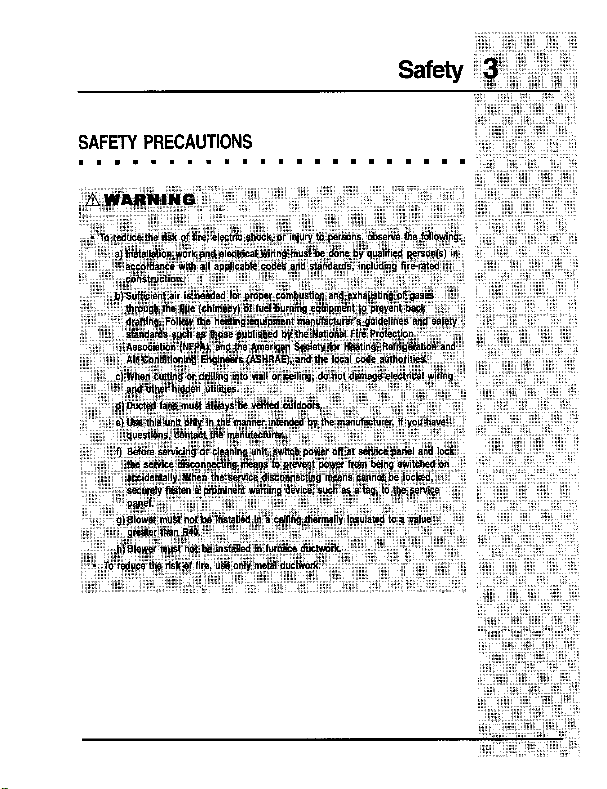
SAFETYPRECAUTIONS
mmmmmnmmmmmmmmmmmmmmm
Safety
:!_i)))i)))i!i)!!J)!))))iii!!)))i)iJi))J)_)_i)))i))]s_)_iO))i)!:)!Y
• ))))i;_i}???ii_))iiO))(_)_(i)))i)!)iJ)?)))?_(i))()i);i)))_
i!!i_!!ii!!iiiiiii!i!!_iiiiiiiiiiii!iiifi!_!!iiiiiiii!!ii!iiii!iiiii_
Page 4

Safety
SAFETYPRECAUTIONS
Page 5

Safety
SAFETYPRECAUTIONS
• • • • • • • • • • • • • • • • • • • •
)i)i)i)J)Ji!i])i)i)))i)))))i!)_ii)i)i_)_)i)_))i)i)i_))i_)ii!))_i)_
))!)i)iiiiiiiii!i!i)_i_il)ii!i_i)!)i)ii?i!_ii)ii!)ii!!iiiiiiiii_ii
Page 6

Finding Information
iii!i!Jiiiiiiii!iiiiiiii
READANDSAVETHESEINSTRUCTIONS
i_i;ili_i_i_;_iii_iiii_;iiiiii!iiiiiiiiiii;!!!ii;i;i_]iii!iiiiiii!ii!il
) i }ii!ii;ii i ' i
:: Read all instructions belore installing the retractable vent.
? : £i i i
;})2)55;;5
?
For your safety, please read and observe all safety instructions. This guide will help
you anticipate all installation connections.
_ 2 1 }
2
}
!;
For toll-free telephone support in the U.S. and Canada:
1-87"/- 4ELECTROLUX (1-8"/7-435-328"/)
For online support and Internet product information:
www,elect roluxu sa.com
_2005 Electrolux Home Products, Inc.
Post Office Box 212378, Augusta, Georgia 30917, USA
All rightsreserved. Printed in the USA
iiii_i!i!iiiiiiii!i!iiiiiiiiii!iiiiiiii!i_!!!iiiiii!i!ii!iiiiiiii!iil
i!!!!!!i_!!i!_ii!!ii!iii!_i_iiiii_ii!!i_i!!_!_i_i!!ii!!ii!!ii!!i!!!!i!i
Page 7

)!)]i))iiJJX!)!;))))J)J;;i(_(iiiJiXJi]i;i))!)))!_X)J)!}!))i!i]i)i
TABLEOFCONTENTS
mmmmm
Safety...................................................................2
ImportantSafetyInstructions..............................2
SafetyPrecautions.............................................3
FindingInformation...........................................6
PleaseReadAndSaveThisGuide...................6
Questions..........................................................6
TableofContents...............................................7
Planningfor Installation....................................8
Inst_llationPlanning...........................................8
SpecificationsandDimensions...........................8
MakingtheElectricalConnection...................13
BlowerInstallation...........................................14
VerifyingOperation..........................................14
FindingInformation
iiiiii i!i!i!!ii@¢!iiiiiiiiii!ii!!iiiiiii!iiii!ililiiii
!i;ili;iii_u;iii_iii;iiiii{i_iii_iiiiiiiii_iiiiiiiiii;_iii;iiii_iii
_ii:!iii_;ii!iiJiii_iii;i!i;ii)Fi_F,iii_i)ii!iiiiiiiiii;_i_i;i;
!_J!_i_i)]!i);))i_)_;))_:t)_({()O(_)i!i))))!i!i;i)!iif!!!i!)!/y)!;!ii
iiii!iliJili)iiiJliil;_iT_i;!ii;i_)_ii!Tii!iiii!_iiJiiiiiiX;iiii!i?
i_iiiiil;iXiiiiiT_iiiiii_iii!iTiiiii_iiiii_iii_iiii_i!_;_i_i_;_!_
)ii;)iii)i)iiil)B))i))]){)_)))O))!_;_i)i)_)i_))i))))!)))))X)!))i_!
_i!{_iii_ili_}i{_ii{iiiiiiiiii_iiiii{i!iiiiii_i?i_i_i!_)_i_iii!ii£1ii
!iii;!iiiiiiiil]!i£i_i_)i;;:iiii)iiiiiiiiiiiiiii)iii;i;_;])!i);;Tii
)i!);iFtT;i4])_)(!_;i)))Xii!))iXi)i));])()i)!i)i)!_)];_!_iij_i)_
Page 8

)i!ii!_!i_!i!_!i
)iiiiiiii!ii_!!!i
Planning for Installation
INSTALLATIONPLANNING
• • • • • • • • • • • • • • • • • n • • • •
A qualified technician must complete the installation of this appliance.
Carefully check the location where the remote blower is to be installed. The remote
blower should be placed for convenient access. Make certain that electrical power
can be provided in the selected location.
Plan the installation so that all minimum clearances are met or exceeded.
Dimensions shown provide minimum clearances, unless otherwise noted.
SPECIFICATIONSANDDIMENSIONS
Blower Overall Dimensions
Top View
Blower Overall Dimensions
Side View
11 _t2"
9 9t!6"
(243mm)
Intake _o)lar
3ischarg_
Figure 2
Page 9

iii:iiii(iiii_iiiiii_iiiiiisiii_{i_iiiiiiii_if[ii!i_i]iii_ii!iiiiii_
* The CFM Fan Rating isvalued at 0" (zero-inch) static pressure.
i!_iiiiii!ii_!iiiii!_iiiiiiiii!ii_iiiii_i_ii!_iiiii_!_ii_i_fiii_iii!
iiiiiiiiiiiiiiliiiiiii!i_ii!iii!ii!iiiiiiiiiiiiiiiiiiiiiiiiiii!iiiiii_
Page 10

i!i!iiiiiiiiiiiii!
iii!i!ii!i!i!i!i!il
Planningfor Installation
iiiiii!ii_
Blower Flat Roof Installation
Roof Curb
Figure 3
Blower Sloped Roof Installation
Figure 4
Page 11

Planning for Installation
Blower Roof Installation
Side View
;iii_!_iiii!ii_iii_i_iiiiiiiiiii_ii_iii_i_ilil)!il)_ii)!i_iii!i_i!!i
- Eibo w
'v
3 IN" x 10"_
45" Ad)us_a hie
Figure 6
• 31/4"x I0"
/,_r_ 90 . Eibo w
J
Page 12

i!iiiii!i!ii
_iiiii!iiiii_i
_iiii_ii!i!iii_
ii_iiii_iiii!i!i
iJii3j!iifiiiiiii!iiiii!
Makingthe ElectricalConnection
ELECTRICALCONNECTION
• • • • • • • • • • • • • • • • • • • • • •
iii!!i!iiiiiiii!ili
)iiiiiiiiiiil
It is the owner's responsibility to ensure that a qualified electrician performs the
electrical connection of this appliance. The electrical installation, including
minimum supply wire size, must comply with the latest revision of the National
Electric Code ANSI/NFPA 70* and local codes and ordinances.
A copy of this standard may be obtained from:
National Fire Protection Association
1 Batterymarch Park
Quincy, Massachusetts 02269-9101
ii_!iiiiiii!iii
iii!iiiiiiiiii!i
%iiiii_ii!!_ii_
Page 13

Installing the Blower
BLOWERINSTALLATION
mmmmmmmmmmmmmmm
Mount the blower to the wall or roof using screws,
through mounting trim flange.
• • • • • • • iT:i_;qiiiii)_!iii))_Jiin_i)i)i)!!i)_)!)i);)i_'!)))i!i;i{i
Wiring of Retractable Ventilation System
(E30OD75ESS, E36DD75ESS, E46DD75ESS
and E48DD75ESS)
VerifyingProperOperation
1 Temporarily re-install the remote blower
cover, using 2 screws per side).
2 Turn on the power supply at the circuit
breaker.
3 Refer to the Retractable Vent Installation
Instructions for further instructions on
verifying the proper operation.
Vent
i dedP_at_:_ c reu breaker
5304444802
....... ,
, _,
_-_u ,
....... ¢
Figure 7 )
ii!iiiiiii
Page 14

L_Electrolux
 Loading...