

Page 1
Use & Care Guide
Freezer
Guia de Uso y Cuidado
Congelador
Guide d’utilisation et d’entretien
Congélateur
A01061401 August 2014
Page 2
2
Finding Information
Please read and save
this guide
Thank you for choosing Electrolux, our
new premium brand in home appliances.
This Use & Care Guide is part of our
commitment to customer satisfaction and
product quality throughout the service life
of your new appliance.
Keep a record for quick
reference
Purchase date
Electrolux model number
Electrolux serial number
NOTE
Registering your product with Electrolux
enhances our ability to serve you. You
can register online at
www.electroluxappliances.com or by
sending your Product Registration Card
in the mail.
Questions?
For toll-free telephone support in the U.S.
and Canada: 1-877-4ELECTROLUX
(1-877-435-3287)
For online support and product information
visit http://www.electroluxappliances.com
Table of contents
Finding Information .............................. 2
Installation Checklist.............................2
Safety .................................................... 3
Feature Overview .................................. 5
Installation ............................................ 6
Installing Door Handle & Leveling ........ 7
Door Removal & Temperature Control. ....9
Electronic Control & Alarms ............... 10
Alarms & Sabbath Mode .................... 11
Air Filt er & Theater™ LED Lighting ....... 12
Water Supply ...................................... 13
Connecting Water Supply .................. 14
Ice Service .......................................... 15
Storage Components ......................... 16
Storage Components &
Energy-Saving Tips.............................17
Care & Cleaning...................................18
Solutions To Common Problems.........20
Warranty Information...........................23
© 2010 Electrolux Home Products, Inc.
10200 David Taylor Drive
Charlotte, NC 28262
Installation Checklist
Doors
Handles are secure and tight
Door seals completely to cabinet on
all sides
Freezer door is level across top
Leveling
Freezer is level, side-to-side and
front-to-back
Toe grille is properly attached to freezer
Cabinet is set solid on all corners
Electrical Power
House power turned on
Freezer plugged in
Air Filter
Air Filter is installed
Final Checks
Shipping material removed
Freezer temperatures set
Water turned on
Registration card sent in
Page 3
Important safety instructions
Safety Precautions
Do not attempt to install or operate your unit
until you have read the safety precautions
in this manual. Safety items throughout this
manual are labeled with a Danger, Warning,
or Caution based on the risk type.
Definitions
This is the safety alert symbol. It is
used to alert you to potential personal injury
hazards. Obey all safety messages that follow
this symbol to avoid possible injury or death.
DANGER
DANGER indicates an imminently
hazardous situation which, if not avoided,
will result in death or serious injury.
WARNING
WARNING indicates a potentially
hazardous situation which, if not avoided,
could result in death or serious injury.
CAUTION
CAUTION indicates a potentially
hazardous situation which, if not avoided,
may result in minor or moderate injury.
IMPORTANT
Indicates installation, operation, or
maintenance information which is
important but not hazard-related.
General Safety
Safety
• Remove all staples from the carton to
avoid injury. Staples can also damage
finishes if they come in contact with
other appliances or furniture.
Child Safety
Packing Materials:
• Packing cartons covered with rugs,
bedspreads, plastic sheets, or stretch
wrap may become airtight chambers
and can quickly cause suffocation.
• Destroy or recycle the product’s carton,
plastic bags, and any other exterior
wrapping material immediately after the
unit is unpacked. Children should never
play with these items.
Child Entrapment and Suffocation:
• These problems are not limited to the
past. Whether junked, abandoned,
or temporarily stored (even for a
few hours), unattended appliances
are dangerous. Please take the
precautions listed below.
Proper Disposal of Appliance
We strongly encourage responsible
appliance recycling/disposal methods.
Check with your utility company or visit
www.energystar.gov/recycle for more
information on recycling your old unit.
Before you recycle or dispose of your
old appliance:
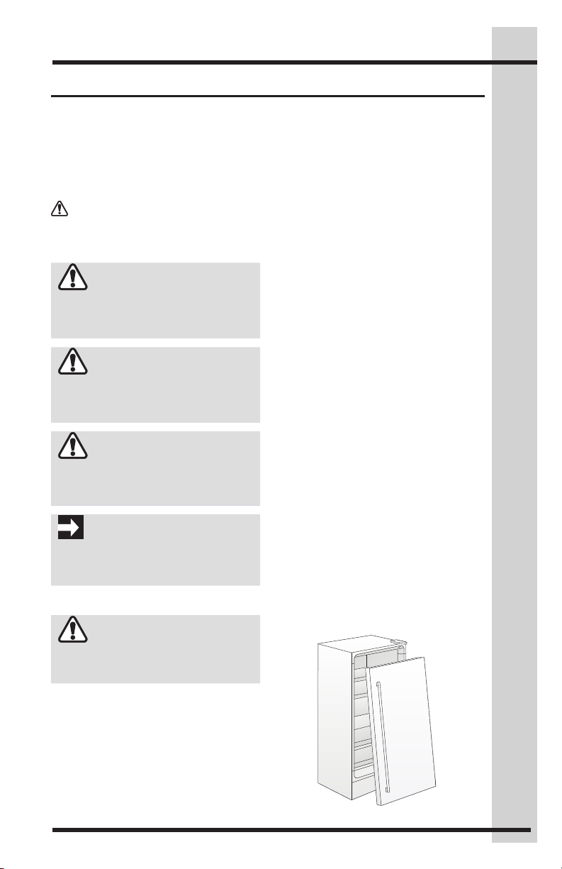
• Remove the doors.
• Leave the shelves and baskets in place
so children may not easily climb inside.
• Have refrigerant and compressor
oil removed by a qualified service
technician.
3
WARNING
Please read all safety instructions
before using your new refrigerator.
• Do not store or use gasoline or other
flammable liquids near this or any
other appliance. Read product labels
for warnings regarding flammability
and other hazards.
• Do not operate the appliance in the
presence of explosive fumes.
• Avoid contact with any moving parts
of the automatic ice maker.
Page 4
4
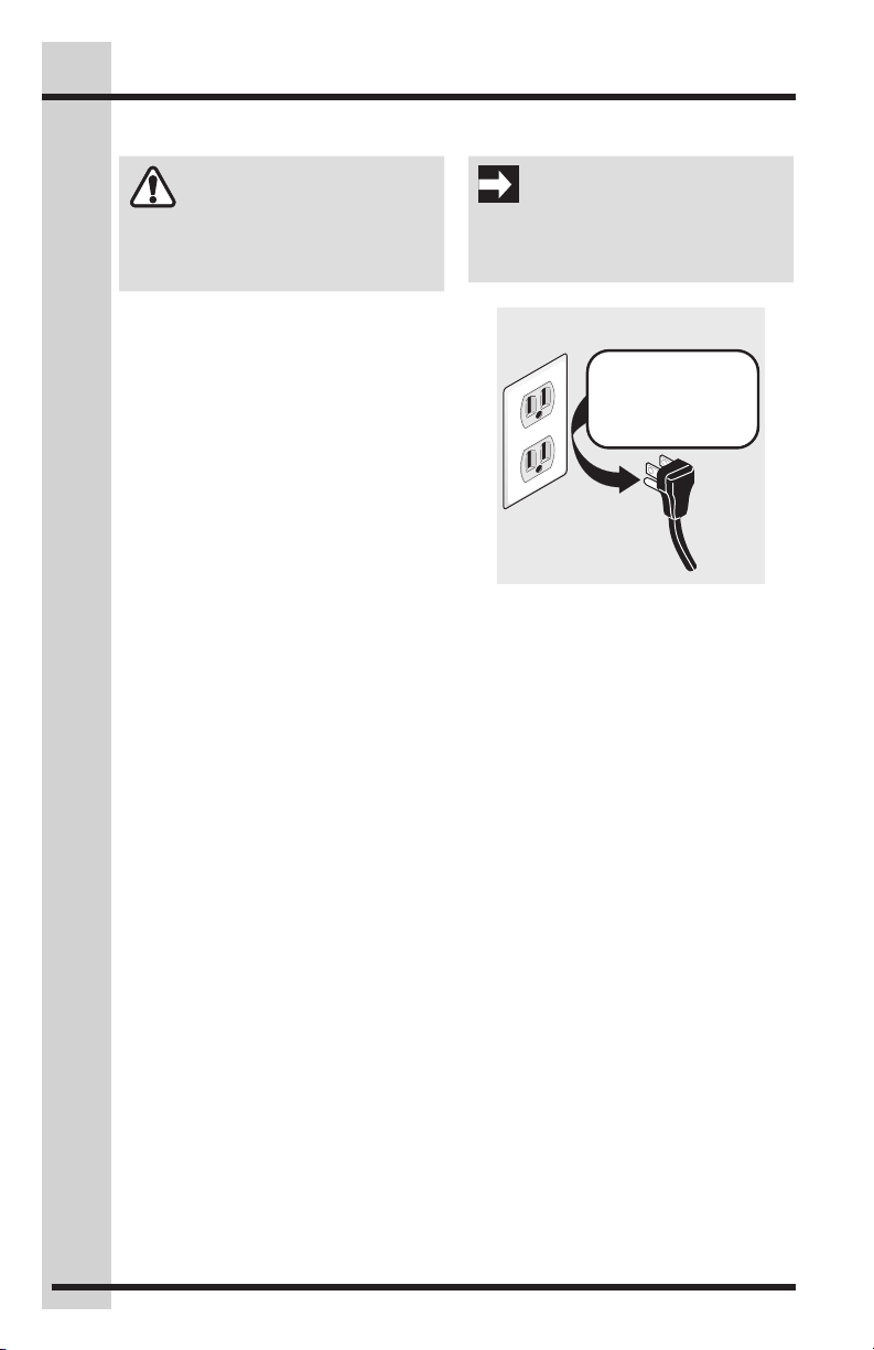
Grounding type wall receptacle
Power cord with
3-prong grounded plug
Do not, under
any circumstances,
cut, remove,
or bypass the
grounding prong.
Safety
Electrical information
WARNING
You must follow these guidelines to
ensure that your appliance’s safety
mechanisms are operating correctly.
• The unit must be plugged into its own
dedicated 115 Volt, 60 Hz, AC-only
non-GFCI electric outlet. The power
cord of the appliance is equipped
with a three-prong grounding
plug for your protection against
electrical shock hazards. It must
be plugged directly into a properly
grounded three-prong receptacle.
The receptacle must be installed in
accordance with local codes and
ordinances. Consult a qualified
electrician. Do not use an extension
cord or adapter plug.
• If the power cord is damaged,
it should be replaced by the
manufacturer, service technician, or a
qualified person.
• Never unplug the appliance by pulling
on the power cord. Always grip the
plug firmly and pull straight out from
the receptacle to prevent damaging
the power cord.
• To avoid electrical shock, unplug
the unit before cleaning and before
replacing a light bulb or LED light.
• Performance may be affected
if the voltage varies by 10% or
more. Operating the appliance with
insufficient power can damage the
compressor. Such damage is not
covered under your warranty.
• Do not plug the unit into an outlet
controlled by a wall switch or pull
cord to prevent the appliance from
being turned off accidentally.
IMPORTANT
To disconnect power to the unit, unplug
the unit or switch the breaker that supplies
power to the unit to the off position.
Page 5
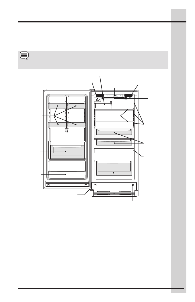
Feature Overview
Switch
LED Ramp-up
Soft Freeze Bin
Ice Bin
Understanding features and terms
Your Electrolux appliance is designed for optimal convenience and storage flexibility. The
illustration below is provided to assist you with familiarizing yourself with product features
and terminology.
NOTE
*Features may vary according to model.
5
Adjustable
Two Liter Bins
w/tall Bottle
Retainer
Condiment
Shelf
Adjustable
Bottom Hinge
Ice Maker
Custom Set™
Electronic
Control
Custom Design
Glass Shelves
Toe Grille
Pure
Advantage
Air Filter
Mid Level
LED Ramp-up
Tall Basket
Light
®
Air
Baffl e
Theater™
Lighting
Baskets
Theater™
Lighting
Page 6
6
Adjustable
Phillips Head
Drive Head
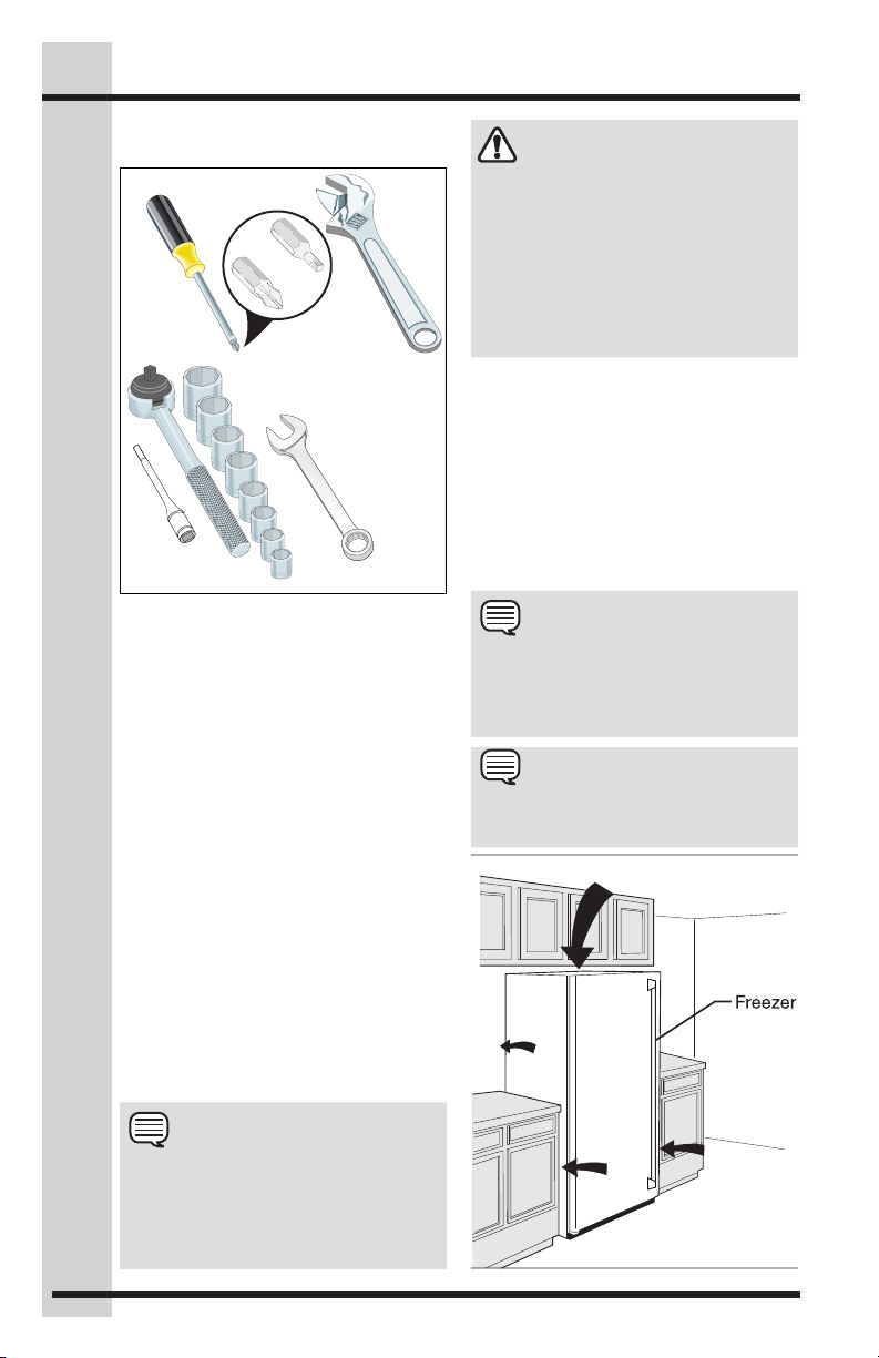
Tools Necessary:
Wrench Set
Installation
Required Tools
You will need the following tools:
Wrench
(OR)
or
#2 Square
Socket
This Use & Care Guide provides general
installation and operating instructions
for your model. We recommend using a
service or kitchen contracting professional
to install your appliance. Use the unit only
as instructed in this Use & Care Guide.
Before starting the appliance, follow
these important first steps.
and
oror
3/8" Fixed
Wrench
Location
• Choose a place that is near a
grounded, non-GFCI, electrical outlet.
Do Not use an extension cord or an
adapter plug.
• If possible, place the unit out of direct
sunlight and away from the range,
dishwasher, or other heat sources.
• The appliance must be installed on a
floor that is level and strong enough
to support a fully loaded unit.
• Consider water supply availability for
models equipped with an automatic
ice maker.
CAUTION
DO NOT install the appliance where the
temperature will drop below 40°F (13°C) or
rise above 110°F (43°C). The compressor
will not be able to maintain proper
temperatures inside the unit.
DO NOT block the toe grille on the
lower front of your appliance. Sufficient
air circulation is essential for the proper
operation of your unit.
Installation
• Allow the following clearances
for ease of installation, proper
air circulation, and plumbing and
electrical connections:
Sides ⅜” (9.5 mm)
Top &Back 1” (25.4 mm)
• Allow for trim kit if it to be installed
with the unit.
NOTE
If your appliance is placed with the door
hinge against a wall, you may have to
allow additional space so the door can
be opened wider.
NOTE
The appliance doors are designed to shut
by themselves within a 20-degree opening.
1” (25 mm)
1”
(25 mm)
NOTE
The exterior walls of the unit may
become quite warm as the compressor
works to transfer heat from the inside.
Temperatures as much as 30ºF warmer
than room temperature can be expected.
(10 mm)
⅜”
⅜”
(10 mm)
Page 7
Installing Door Handle & Leveling
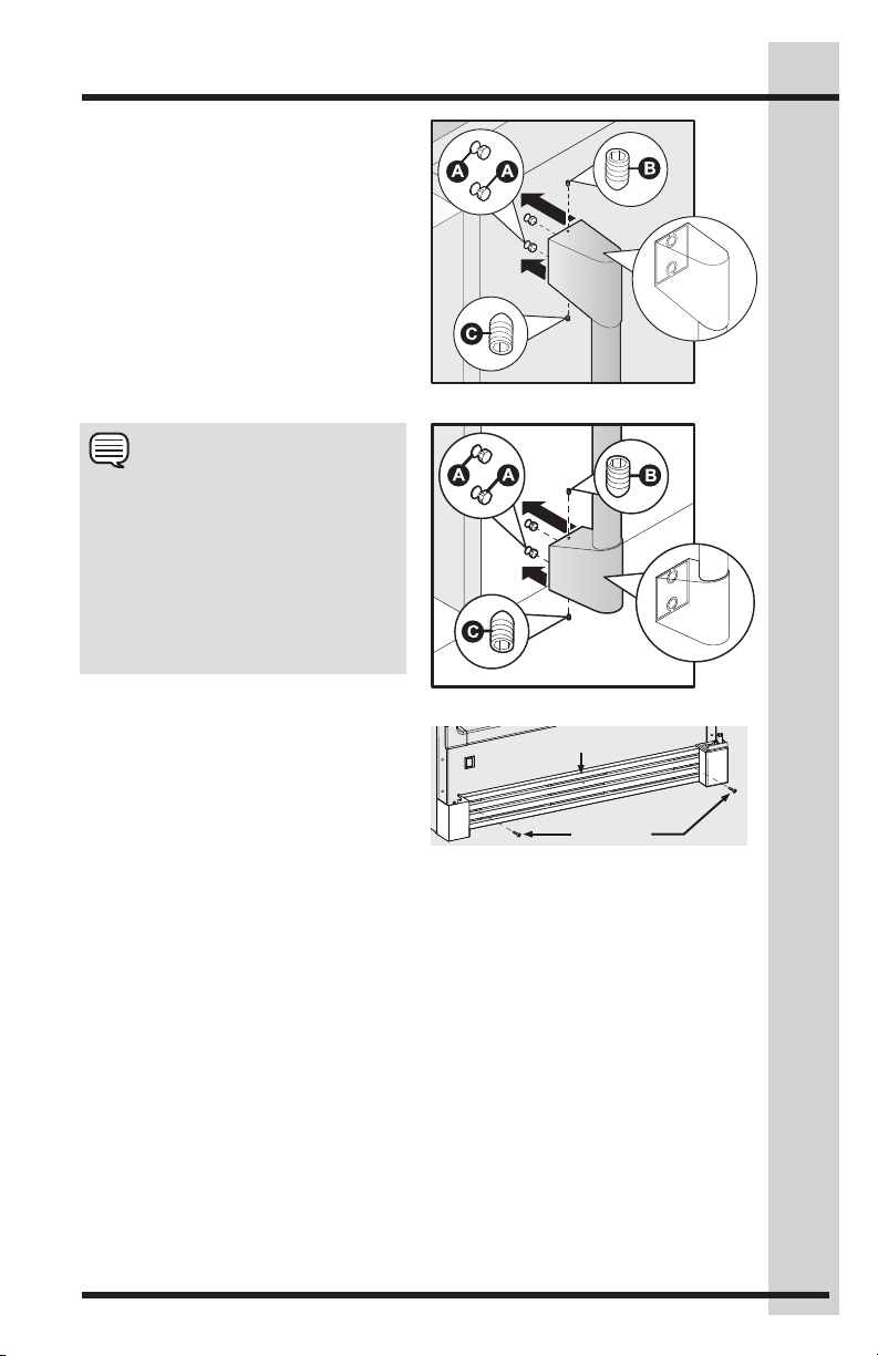
Door Handle
Mounting Instructions
1. Remove handle from carton and any
other protective packaging.
2. Position handle end caps over upper
and lower preinstalled shoulder bolts
(A) that are fastened into door.
3. While holding handle firmly against
door, fasten upper and lower Allen
set screws (B) with supplied Allen
wrench until there is no gap between
handle and door.
NOTE
All set screws should be tightened so the
screw is below the surface of the handle.
The handles should be drawn tight to
freezer and refrigerator doors with no gaps.
Opening the opposite door while tightening
the Allen screw makes installation easier.
The door handle may loosen over time or if
it was installed improperly. If this happens,
tighten the set screws on the handles.
7
Toe Grille Removal
To remove the toe grille, use a Phillips
screwdriver and remove the two screws
holding the toe grille to the cabinet. Then
pull the toe grille away from the unit.
Leveling
• The freezer must have all bottom
corners resting firmly on a solid floor.
• The floor must be strong enough to
support a fully loaded freezer.
• It is VERY IMPORTANT for your
freezer to be level in order to function
properly. If the freezer is not leveled
during installation, the door may be
misaligned and not close or seal
properly, causing cooling, frost or
moisture problems.
Toe Grille
Remove
Screws
Page 8
8
Leveling
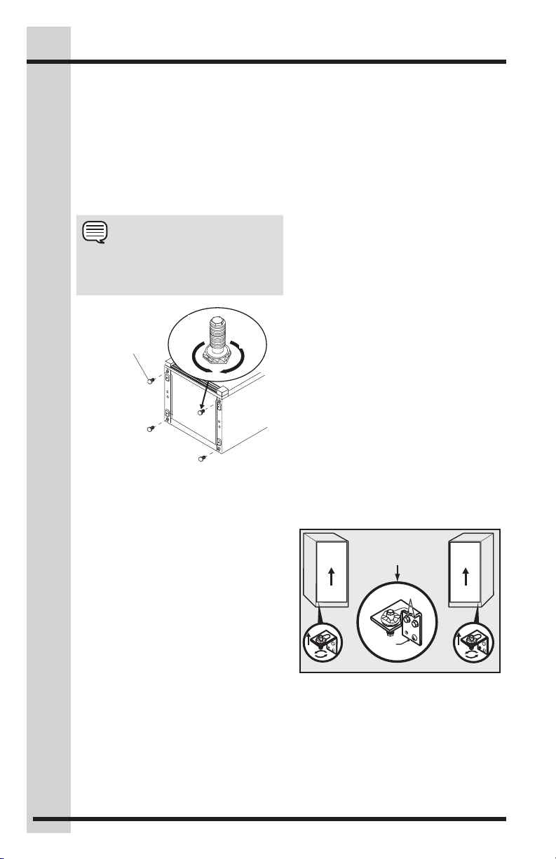
To Level The Freezer:
While unit is lying on its back, note the
location of the 4 leg levelers installed at
each corner. These leg levelers will be
used to level the freezer and to adjust the
height. Use a carpenter’s level to level the
freezer from front to back and side to side.
Adjust the plastic leveling feet in front, ½
bubble higher, so that the door closes
easily when left halfway open.
NOTE
Make sure to allow for the Trim and
Leveling Kit if it is to be installed with
the unit.
Turn
Plastic
Leveling Feet
Right to
Lower
Leveling Instructions For
Matching Tall Refrigerator / Tall
Freezer Pair:
• Level door of first unit using all four
levelers and slide unit into place.
Recheck for levelness and adjust
if necessary.
• Measure distance from floor to
bottom of door on first unit. Adjust
and level second unit so door
height matches.
• Leg Level Adjustments:
One full turn of all 4 leg levelers will
raise door 5/32”.
• Slide second unit into place leaving a
minimum gap of 3/16” between units
for door swing clearance.
• This last step may require at least
one extraction of the second
unit to properly align units in a “builtin” application.
Turn
Left to
Raise
Leveling Door with
Adjustable Hinge
Use the lower hinge adjustment to fine
tune the door height and for final cabinet
spacing. Use a 7/16” socket or wrench
to adjust the screw at the bottom of the
lower hinge.
Adjusting Doors For Matching Tall
Refrigerator / Tall Freezer Pair
The doors may also be adjusted side to
side with the slotted hinge for aligning
the doors parallel to each other. Loosen
the two bolts with a ⅜” wrench and one
screw with a Phillips screwdriver. Shift
the doors until parallel, then retighten the
screws securely. (See illustration below.)
Lower Hinge Adjustment For
Leveling The Doors Of The
Matching Tall Refrigerator / Tall
Freezer Pair
To level the doors using the adjustable
lower hinge (some models):
1. If the refrigerator door is lower than
the freezer door, raise the refrigerator
door by turning the adjustment screw
clockwise using a 7/16” socket
wrench. (See illustration below.)
2. If the freezer door is lower than the
refrigerator door, raise the freezer
door by turning the adjustment screw
clockwise using a 7/16” socket
wrench. (See illustration below.)
Door
Slotted Hinge
Adjustment
3/8" bolts
Screw
Door
Raise
Door
Door
Raise
Freezer Refrigerator
Page 9
Door Removal & Temperature Control
Door Removal
If door must be removed:
CAUTION
Doors are heavy. Two people are recommended to remove or replace the door
assembly from the cabinet.
9
• Unplug the unit or switch the breaker
that supplies power to the unit to the
off position.
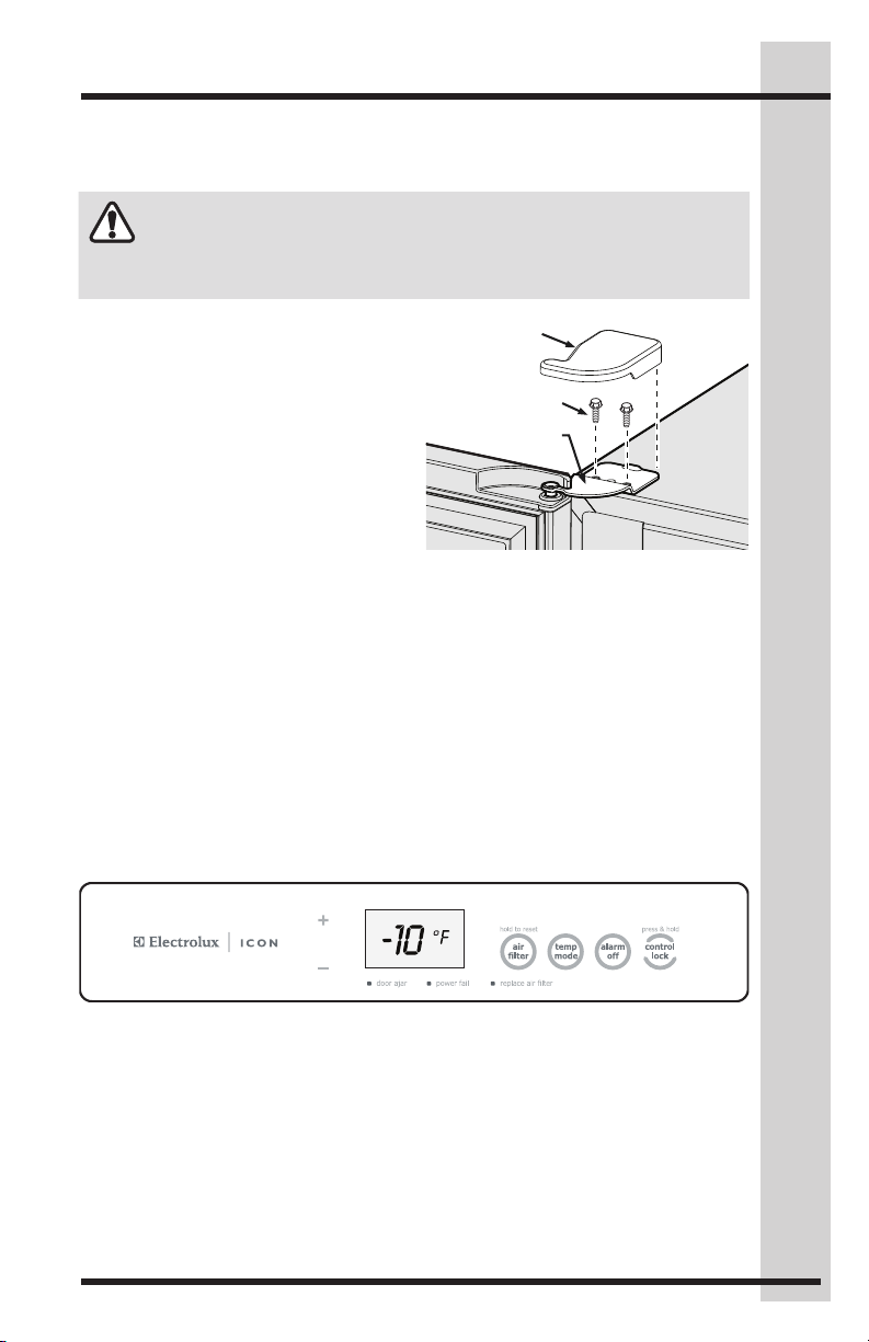
• Remove the plastic top hinge cover.
• Hold the door in place while removing
the top hinge from the cabinet.
• Remove the two ⅜” hex head bolts
from the top hinge with a ⅜” wrench
or socket.
• Lift the door upwards and pull up
and away from the cabinet until free
of the bottom hinge pin mounted on
the front of the cabinet.
• To replace the door, reverse the above
procedures and securely tighten all
screws to prevent hinge slippage.
Hinge Cover
Hinge Bolts (2)
Hinge Plate
Setting The Custom Set™ Electronic Control
COOL DOWN PERIOD
For safe food storage, allow 4 hours for the appliance to cool down completely. The unit
will run continuously for the first several hours.
CUSTOM SET™ ELECTRONIC CONTROL
The Custom Set™ Electronic Control is located inside the appliance. Temperature is
factory preset to provide satisfactory food storage temperatures. However, the temperature
control is adjustable to provide a range of temperatures for your personal satisfaction.
To adjust the temperature setting, press the UP (+) key for warmer temperature and DOWN
(-) key for colder temperature on the control panel. Allow several hours for the temperature
to stabilize between adjustments. The unit can be adjusted between -10°F (-23°C) and
10°F (-12°C).. By pressing the TEMP MODE key, the temperature display will toggle
between °F to °C.
To turn the appliance OFF, press the UP (+) key until the warmest temperature setting of
10°F (-12°C). show in the display. Then press the UP (+) key 3 times within 3 seconds to
turn the unit OFF. The display will then scroll “OFF” across the display. To turn the unit back
ON, press the DOWN key 3 times within 3 seconds. The control will then display “10°F
(-12°C).)” and may be adjusted to the desired temperature.
Page 10
10
Electronic Control & Alarms
Custom Set™ Electronic Control Features
Replace Air Filter
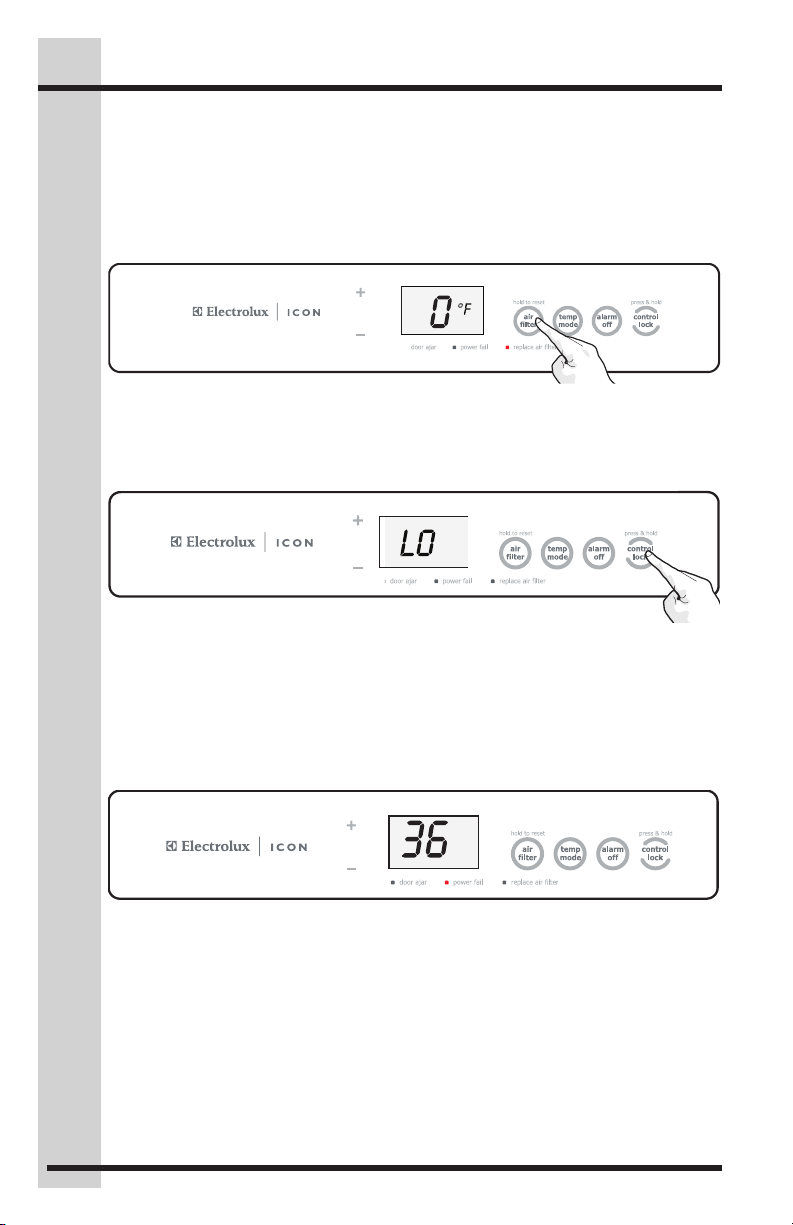
When the “REPLACE AIR FILTER” LED is illuminated yellow, the air filter needs to be
replaced. The control will signal for air filter replacement after 3600 hours of operation.
After replacing the air filter, reset the air filter timer by pressing the AIR FILTER key for
3 seconds. The “REPLACE AIR FILTER” LED will be illuminated green for 3 seconds,
confirming a timer reset.
Control Lock
To disable the keypads on the control, begin by pressing the CONTROL LOCK key for
3 seconds until “LO” is displayed for 1 second. With the control locked, when keys are
pressed on the control panel, “LO” will be displayed. To unlock the control, press the
CONTROL LOCK key for 3 seconds. The display will show “UL” for 1 second.
Power Fail
The POWER FAIL indicator light informs you that due to a power failure the cabinet
temperature exceeded 23ºF (-5ºC). If the power failure lasted more than 1 hour the
display alternates between showing the power failure duration (Hours and DURATION
LED illuminate in the display) and the cabinet temperature (ºF or ºC illuminates) every ½
second. This safety feature will aid in determining what food spoilage action to take.
The Power Fail indicator light and duration display can be turned off by pressing the
Alarm Off Key.
°F
HRS
HI TEMP DURATION
Alarms
There are 4 possible conditions that will cause the alarm tone to sound.
High Temp Alarm
If the temperature inside the cabinet exceeds 23°F (-5°C), the HIGH TEMP LED
will illuminate, and after 1 hour, the HIGH TEMP Alarm will sound and the cabinet
temperature is shown in the display. The LED and temperature alarm will remain active
until the cabinet temperature is below 23ºF (-5ºC).
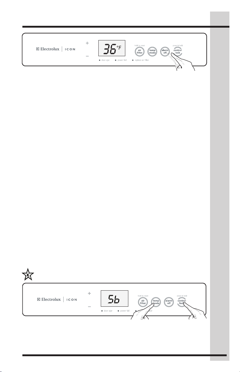
The audible alarm can be turned off by pressing ALARM OFF key.
Page 11
Alarms & Sabbath Mode
Door Ajar Alarm
This alarm will sound to alert you that the door has been open for 5 minutes or more. The
DOOR AJAR LED will illuminate and the audible alarm will sound until the door is closed.
The audible alarm can be turned off by pressing the ALARM OFF key or by closing the
door. If the door is ajar for 15 minutes, the interior light will turn off.
Temp Sensing Error Alarm
The sensor alarm signals you that a problem exists with a temperature sensor. The
audible alarm will sound after 1 hour and the display will alternate between “E8” or “E9”
and -10°F (-23°C) at ½ second intervals. The control will then enter a mode that runs the
appliance in a manner that maintains the factory set cabinet temperature.
The audible alarm can be turned off by pressing the ALARM OFF key.
Stuck Key Alarm
The stuck key alarm will sound if the control reads a keypress for longer than 30
seconds. The audible alarm will sound and will be limited to 1 minute and will stop
automatically. The display will alternate between “E7” and -10°F (-23°C) at ½ second
intervals. The control will then enter a mode that runs the unit in a manner that maintains
the factory set cabinet temperature until the condition is resolved.
The audible alarm can be turned off by pressing the ALARM OFF key.
11
Sabbath Mode
The Sabbath Mode is a feature that disables portions of the appliance and its controls in
accordance with the observance of the weekly Sabbath and religious holidays within the
Orthodox Jewish community.
To initiate or cancel Sabbath Mode, press the CONTROL LOCK and TEMP MODE keys
at the same time and hold for 3 seconds. The display will now show “Sb” and the confi
rmation tone will sound. When AC power is cycled while the control is in Sabbath mode,
the control enters into Sabbath mode automatically. “Sb” will again be displayed. While in
Sabbath Mode, the display will show “Sb” for one second if any key is pressed.
In the interest of food safety, only the HIGH TEMP Alarm remains active and takes
precedence over other Sabbath Mode features.
For further assistance, guidelines for proper usage and a complete list of models
with the Sabbath feature, please visit the web at http:\\www.star-k.org.
Page 12
12
connection
Air Filter
Air Filter & TheaterTM LED Lighting
Pure Advantage™ Air
Filter
Your new Pure AdvantageTM air filter is
located inside one of the 2-Liter Door
Bins. The air filter cover is located on
the upper right side of the control box.
In general, you should change the air
filter with Part Number “EAFCBF” every
6 months to ensure optimal filtering of
freezer odors. The replacement air filter
can be purchased on the Electrolux ICON
website (http://www.electroluxicon.com)
or call toll free in the U.S. and Canada:
1-877-4ELECTROLUX (1-877-435-3287).
Your electronic control is equipped with a
Change Filter Indicator to remind you to
change your filter. See “Replace Air Filter”.
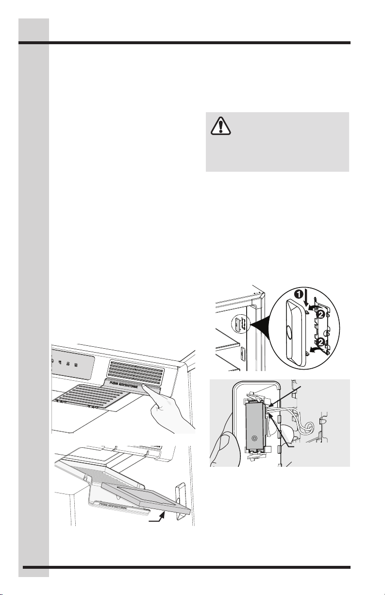
To Install Or Replace The Air
Filter
• Pull down on the front of the Pure
Advantage™ air filter cover. This
releases the hinged bottom cover to
drop open.
• Remove the old filter and discard it.
• Unpackage the new filter and place it
inside the hinged bottom cover of the
housing.
• Push the hinged bottom cover
upward until the tab snaps into
closed position.
Theater™ LED Lighting
The interior cabinet lighting features LED
lights that gradually ramp up in intensity
after the door is opened.
To replace an LED:
WARNING
Unplug the unit or switch the breaker
that supplies power to the unit to the off
position before changing an LED light.
1. Unplug the electrical cord or switch
OFF the power supply breaker.
2. Push down on the LED cover and then
pull away from the cabinet interior.
3. From the inside of the LED cover,
remove the wire harness connector
by pressing on the latch with a small
flat-bladed screwdriver. Pull the wire
harness connector out of the LED.
4. Replace with a new LED and install in
the reverse order.
press & hold
temp
alarm
mode
control
off
lock
Open air filter cover
Remove air filter
Push on
underside of
connector to
release latch
Remove wire
harness
Page 13
Water Supply
WARNING
To avoid electric shock, which can cause death or severe personal injury, disconnect
the appliance from electrical power before connecting a water supply line to the unit.
CAUTION
To Avoid Property Damage:
• Copper or Stainless Steel braided tubing is recommended for the water
supply line. Water supply tubing made of ¼ inch plastic is not recommended
to be used. Plastic tubing greatly increases the potential for water leaks, and
the manufacturer will not be responsible for any damage if plastic tubing is
used for the supply line.
• DO NOT install water supply tubing in areas where temperatures fall below freezing.
• Chemicals from a malfunctioning softener can damage the ice maker. If the
ice maker is connected to soft water, ensure that the softener is maintained
and working properly.
IMPORTANT
Ensure that your water supply line connections comply with all local plumbing codes.
Before Installing The Water Supply Line, You Will Need:
• Basic Tools: adjustable wrench, flat-blade screwdriver, and Phillips screwdriver
• Access to a household cold water line with water pressure between 30 and 100 psi.
• A water supply line made of ¼ inch (6.4 mm) OD, copper or stainless steel tubing. To
determine the length of tubing needed, measure the distance from the ice maker inlet
valve at the back of the freezer to your cold water pipe. Then add approximately 7
feet (2.1 meters), so the freezer can be moved out for cleaning (as shown).
• A shutoff valve to connect the water supply line to your household water system.
DO NOT use a self-piercing type shutoff valve.
• A compression nut and ferrule (sleeve) for connecting a copper water supply line to
the ice maker inlet valve.
13
Page 14
14
Connecting Water Supply
freezer as shown and arrange coils
NOTE
Check with your local building authority
for recommendations on water lines and
associated materials prior to installing
your new refrigerator. Depending
on your local/state building codes,
Electrolux recommends for homes
with existing valves its Smart Choice®
water line kit 5305513409 (with a
6-ft. Stainless Steel Water Line) and
for homes without an existing valve,
Electrolux recommends its Smart
Choice® water line kit 5305510264
(with a 20-ft. copper water line with
self-tapping saddle valve). Please refer
to www.electroluxappliances.com for
more information.
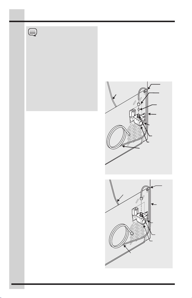
To Connect Water Supply Line
To Ice Maker Inlet Valve:
1. Disconnect freezer from electric
power source.
2. Place end of water supply line into
sink or bucket. Turn ON water supply
and flush supply line until water
is clear. Turn OFF water supply at
shutoff valve.
3. Remove plastic cap from water valve
inlet and discard cap.
4. If you use copper tubing - Slide
brass compression nut, then ferrule
(sleeve) onto water supply line. Push
water supply line into water valve inlet
as far as it will go (¼” / 6.4 mm). Slide
ferrule (sleeve) into valve inlet and
finger tighten compression nut onto
valve. Tighten another half turn with
a wrench; DO NOT overtighten. See
Figure 1.
If you use stainless steel tubing
- The nut and ferrule are already
assembled on the tubing. Slide
compression nut onto valve inlet and
finger tighten compression nut onto
valve. Tighten another half turn with
a wrench; DO NOT overtighten. See
Figure 2.
5. With steel clamp and screw, secure
water supply line (copper tubing only)
to rear panel of freezer as shown.
6. Coil excess water supply line (copper
tubing only), about 2½ turns, behind
so they do not vibrate or wear
against any other surface.
7. Turn ON water supply at shutoff valve
and tighten any connections that leak.
8. Reconnect freezer to electrical
power source.
9. To turn ice maker on, lower wire
signal arm (side mounted) or set the
ice maker’s On/Off power switch to
the “I” position (rear mounted).
Plastic Water Tubing
to Ice Maker
Fill Tube
Compression
(Sleeve)
water line
Water Valve
Valve Inlet
Water Valve
Copper water line
from household
water supply
(Include enough tubing in loop to
allow moving refrigerator out
Figure 1
Plastic Water Tubing
to Ice Maker
Fill Tube
6 ft. Stainless Steel water line
from household water supply
Figure 2
for cleaning)
water Line
Water Valve
Valve Inlet
Water Valve
Steel
Clamp
Brass
Nut
Ferrule
Copper
Bracket
Steel
Clamp
Stainless
Steel
Bracket
Page 15
If your freezer has an automatic icemaker,
Signal Arm
it will provide a sufficient supply of ice
for normal use. During the initial startup
of your freezer, however, no ice will be
produced during the first 24 hours of
operation. Automatic ice makers are also
optional accessories that may be installed
in some models at any time. Call your local
dealer for information.
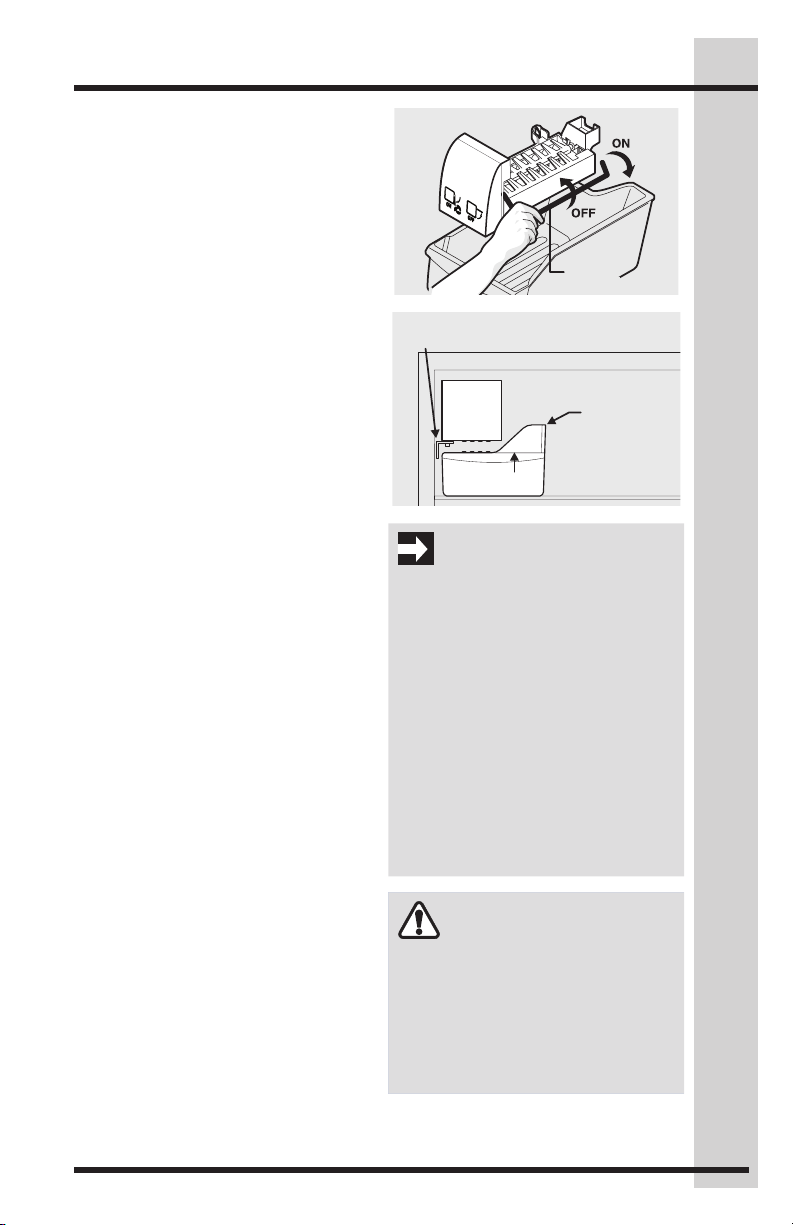
Turning Your Ice Maker On
After the plumbing connections have been
completed, the water supply valve must
be opened. Place the ice container under
the ice maker, pushing it as far back as
possible. Lower the wire signal arm to its
“down” or ON position. New plumbing
connections may cause the first production
of ice cubes to be discolored or have an
odd flavor. These first cubes should be
discarded until the cubes produced are free
of discoloration and taste.
Turning Your Ice Maker Off
To stop the ice maker, lift the wire signal
arm until it clicks and locks in the “up” or
OFF position. The ice maker also turns
off automatically when the ice container is
full. If your model has an adjustable freezer
shelf, place the shelf in the lower position,
so that the wire signal arm will hit the ice
when the container is full.
Ice Maker Tips
• If the ice maker will be turned off for
a long period of time, turn the water
supply valve to the closed position.
• Ice cubes stored too long may
develop an odd flavor. Empty the
ice container and ensure that the
wire signal arm is in its “down” or
ON position. The ice maker will then
produce more ice.
• Occasionally shake the ice container
to keep ice separated.
• Keep the wire signal arm in its “up”
or OFF position until the freezer is
connected to the water supply or
whenever the water supply is turned off.
• The following sounds are normal
when the ice maker is operating:
• Motor running
• Ice loosening from tray
• Ice dropping into ice container
• Running water
• Water valve opening or closing
Ice Service
Wire
Leveling Bracket
Ice
Container
IMPORTANT
Your ice maker is shipped with the wire
signal arm in the ON position. To ensure
proper function of your ice maker, hook
up water supply immediately or turn ice
maker OFF by lifting the wire signal arm
until it clicks and locks in the UP position.
Check the leveling bracket on the ice
maker to ensure the ice maker is level.
If the gap between the freezer wall and
the ice maker is the same at top and
bottom, then ice maker is level. If the ice
maker is not level, loosen the screw and
slide the bracket to the correct position
to make it level. Retighten the screw.
You will need a ¼” socket wrench for
this task.
CAUTION
• DO NOT place the ice container
in dishwasher.
• Wash the ice container in warm
water with mild detergent. Rinse
well and dry.
• Stop the ice maker when cleaning
the freezer and during vacations.
15
Page 16
16
Storage Components
Custom Design™ Glass Shelves
Multi-position adjustable slide out glass
shelves can be moved to any position for
larger or smaller packages. The shipping
spacers that stabilize the shelves for
shipping may be removed and discarded.
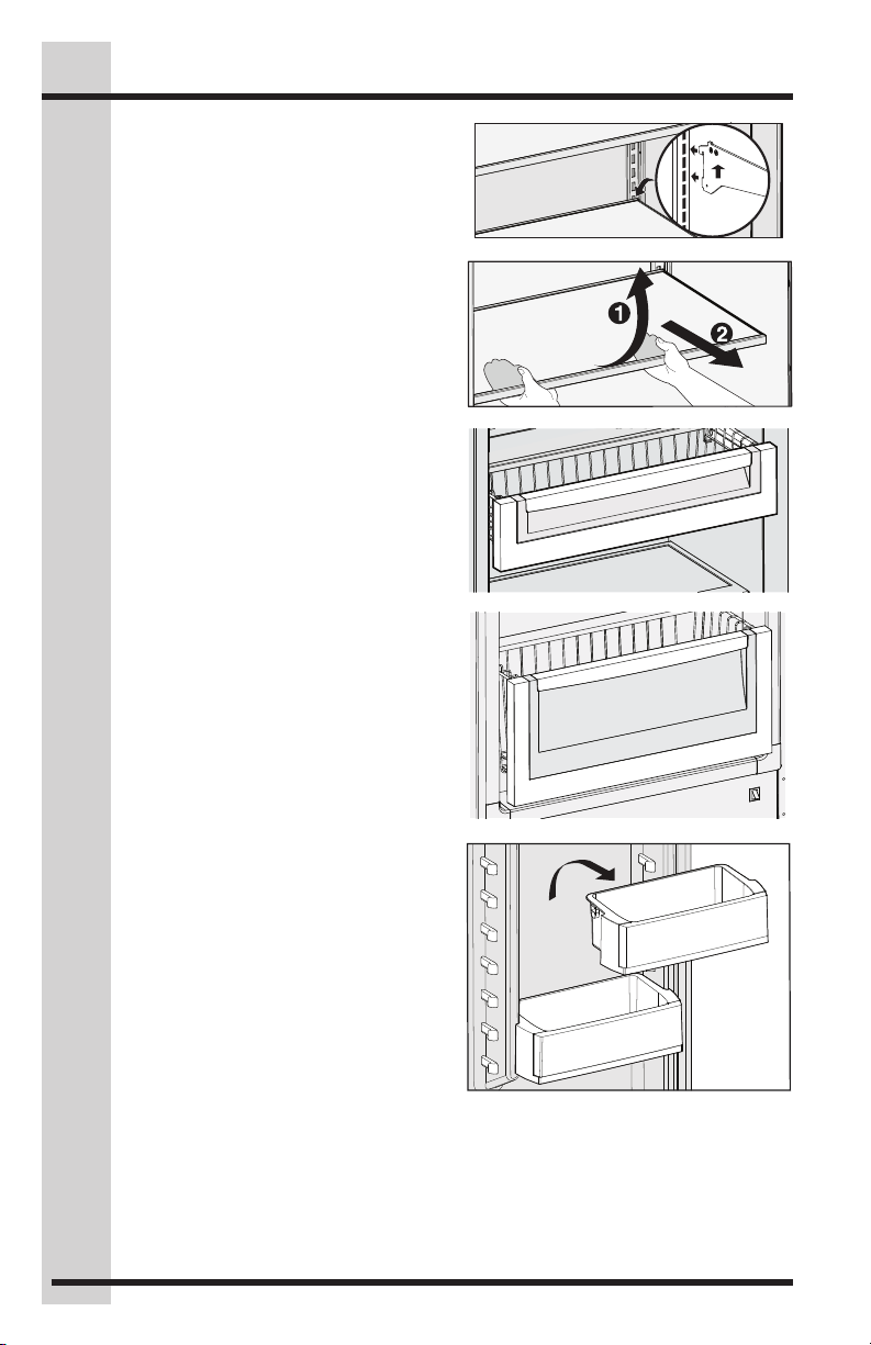
To Adjust The Shelves
• Lift front edge up.
• Pull shelf out.
• Replace the shelf by inserting the
hooks at rear of the shelf into the
wall bracket. Lower the shelf into the
desired slots and lock into position.
Mid Level Baskets
This model is equipped with 2 mid-level
baskets for convenient storage of small items.
Tall Lower Basket
The tall lower basket is ideal for large items
or items that do not store well on
the shelves.
Insert into
slots
To remove the Mid-Level and
Tall Lower Basket:
Pull up on the front of the basket to
release the basket from the retainers on
the interior sides of the freezer.
Adjustable Door Bins
This model is equipped with adjustable
door bins that can be moved to suit
individual needs.
To Move Door Bins:
• Lift the bin straight up.
• Remove the bin.
• Place the bin in desired position.
• Lower the bin onto supports until
locked in place.
Page 17
Storage Components & Energy-Saving Tips
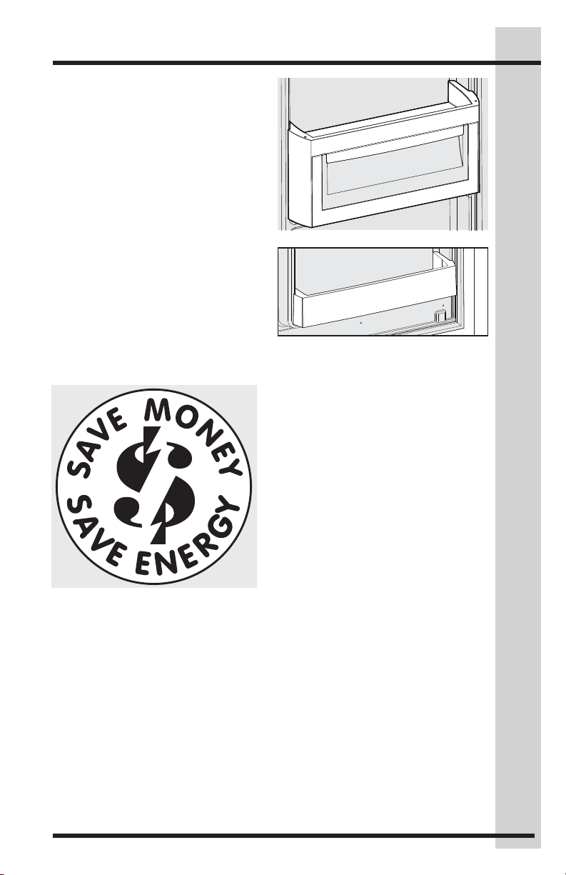
Soft Freeze Tilt-Out Bin
The soft freeze tilt out bin is designed to
be warmer than the freezer compartment.
It is ideal for keeping ice cream and frozen
yogurt ready to serve.
Condiment Shelf
The condiment shelf is designed to hold small
items to help keep your freezer organized.
Energy-Saving Tips
• Locate the unit in the coolest part of
the room, out of direct sunlight, and
away from heating ducts or registers.
Do not place the unit next to heatproducing appliances such as a
range, oven, or dishwasher. If this is
not possible, a section of cabinetry or
an added layer of insulation between
the two appliances will help the unit
operate more efficiently.
• Level the appliance so that the door
closes tightly.
• Refer to the “SETTING THE
TEMPERATURE CONTROL” section
for the suggested temperature
control settings.
• Do not overcrowd the unit or block cold air vents. Doing so causes the appliance to
run longer and use more energy.
• Cover foods and wipe containers dry before placing them in the unit. This cuts
down on moisture build-up inside the unit.
• Organize the appliance to reduce door openings. Remove as many items as
needed at one time and close the door as soon as possible.
17
Page 18
18
Care & Cleaning
Vacation And Moving Tips
Short Vacations:
Leave the unit operating during vacations of less than three weeks.
Long Vacations:
If the appliance will not be used for
several months:
• Remove all food and unplug the power cord.
• Clean and dry the interior thoroughly.
• Leave the door open slightly, blocking it open if necessary, to prevent odor and
mold growth.
Moving: When moving the unit, follow these guidelines to prevent
damage:
• Disconnect the power cord plug from the wall outlet.
• Remove foods, then defrost, and clean the appliance.
• Secure all loose items such as
base panel, baskets, and shelves by taping them securely in place to prevent damage.
• In the moving vehicle, secure the unit in an upright position to prevent movement.
Also protect outside of the appliance with a blanket, or similar item.
Care & Cleaning
Keep your unit clean to prevent odor build-up. Wipe up any spills immediately and clean
at least twice a year. Never use metallic scouring pads, brushes, abrasive cleaners
or strong alkaline solutions on any surface. Do not wash any removable parts in a
dishwasher. Always unplug the electrical power.
CAUTION
• When moving the appliance pull straight out. Do not shift the unit from side to
side as this may tear or gouge the floor covering.
• Damp objects stick to cold metal surfaces. Do not touch interior metal surfaces with
wet or damp hands.
CAUTION
• Turning the temperature control to “OFF” (See Custom SetTM Electronic Control)
turns off the compressor, but does not disconnect electrical power to the LED
lights or other electrical components. Unplug the unit or switch the breaker that
supplies power to the unit to the off position.
• Do not use razor blades or other sharp instruments which can scratch the
appliance surface when removing adhesive labels. Any glue left from tape or
labels can be removed with a mixture of warm water and mild detergent, or, touch
the glue residue with the sticky side of tape you have already removed. Do not
remove the serial plate.
Page 19
Care & Cleaning
NOTE
• Do Not use abrasive cleaners such as window sprays, scouring cleansers,
flammable fluids, cleaning waxes, concentrated detergents, bleaches, or
cleansers containing petroleum products on plastic parts, interior doors, gaskets,
or cabinet liners. Do not use paper towels, scouring pads or other abrasive
materials.
• Never use metallic scouring pads, brushes, abrasive cleaners or strong alkaline
solutions on any surface.
• Do not wash any removable parts in a dishwasher.
• Always unplug the electrical power.
Care and cleaning tips
Part Cleaning Agents Tips and Precautions
Interior &
Door Liners
Door Gaskets • Soap and water • Wipe gaskets with a clean soft cloth.
Drawers &
Bins
Glass
Shelves
Exterior &
Handles
Exterior &
Handles
(Stainless
Steel Models
Only)
• Soap and water
• Baking soda and
water
• Soap and water • Use a soft cloth to clean drawer runners and tracks.
• Soap and water
• Glass cleaner
• Mild liquid sprays
• Soap and water
• Non abrasive glass
cleaner
• Soap and water
• Ammonia
• Stainless steel
cleaners
• Use 2 tbsp. (25 g) of baking soda in 1 qt. (1 l)
warm water.
• Be sure to wring excess water out of sponge or
cloth before cleaning around controls, light bulb
or any electrical part.
• Do not wash any removable items (bins,
drawers, etc.) in dishwasher.
• Allow glass to warm to room temperature before
immersing in warm water. Sudden temperature
changes can cause glass breakage.
• Do not use commercial household cleaners
containing ammonia, bleach or alcohol to
clean handles.
• Use a soft cloth to clean smooth handles.
• Do not use a dry cloth to clean smooth doors.
• Never use CHLORIDE or cleaners with bleach
to clean stainless steel.
• Clean stainless steel front and handles with
non-abrasive soapy water and a dishcloth.
Rinse with clean water and a soft cloth.
• Wipe stubborn spots with an ammonia-soaked
paper towel, and rinse. Use a non-abrasive
stainless steel cleaner. These cleaners can
be purchased at most home improvement
or major department stores. Always follow
manufacturer’s instruction.
• NOTE: Always clean, wipe and dry with grain to
prevent scratching.
• Wash the rest of the cabinet with warm water
and mild liquid detergent. Rinse well and wipe
dry with a clean soft cloth.
19
Page 20
20
Solutions to Common Problems
Troubleshooting Guide
Before calling for service, review this list. It may save you time and expense. This list
includes common occurrences that are not the result of defective workmanship or
materials in this appliance.
Concern Potential Cause Common Solution
Appliance Operation
Appliance does
not run.
Appliance runs
too much or
too long.
Interior
temperature is
too cold.
Interior
temperature is
too warm.
External surface
temperature is
warm.
• Appliance is plugged
into a circuit that has a
ground fault interrupt.
• Temperature control set
to “OFF”.
• Appliance may not be
plugged in, or plug may
be loose.
• House fuse blown or
tripped circuit breaker.
• Power outage.
• Room or outside
weather is hot.
• Appliance has recently
been disconnected for
a period of time.
• Large amount of warm
or hot food have been
stored recently.
• Door is opened too
frequently or kept open
too long.
• Door may be slightly open
• Temperature control is
set too low.
• Appliance gaskets are
dirty, worn, cracked or
poorly fitted.
• Temperature control is
set too low.
• Temperature control is
set too warm.
• Door is opened too
frequently or kept open
too long.
• Door may be
slightly open.
• Large amount of warm
or hot food have been
stored recently.
• Appliance has recently
been disconnected for
a period of time.
• The external walls can be
as much as 30ºF warmer
than room temperature.
• Use another circuit. If you are
unsure about the outlet, have it
checked by a certified technician.
• See “Setting the Custom Set™
Electronic Control” section.
• Ensure plug is tightly pushed
into outlet.
• Check/replace fuse with a
15-amp time delay fuse. Reset
circuit breaker.
• Check house lights. Call local
Electric Company.
• It’s normal for the appliance to work
harder under these conditions.
• It takes 24 hours for the appliance
to cool down completely.
• Warm food will cause the
appliance to run more until the
desired temperature is reached.
• Warm air entering the Freezer
causes it to run more. Open the
door less often.
• See “DOOR PROBLEMS”.
• Set control to a warmer setting.
Allow several hours for the
temperature to stabilize.
• Clean gaskets (See Care and
Cleaning Chart). Worn, cracked or
poorly fitting gaskets should
be replaced.
• Set control to a warmer setting.
Allow several hours for the
temperature to stabilize.
• Set control to a colder setting.
Allow several hours for the
temperature to stabilize.
• Warm air entering the appliance
causes it to run more. Open the
door less often.
• See “DOOR PROBLEMS”.
• Wait until the appliance has
had a chance to reach its
selected temperature.
• Appliance requires 24 hours to
cool down completely.
• This is normal while the
compressor works to transfer heat
from inside the cabinet.
Page 21
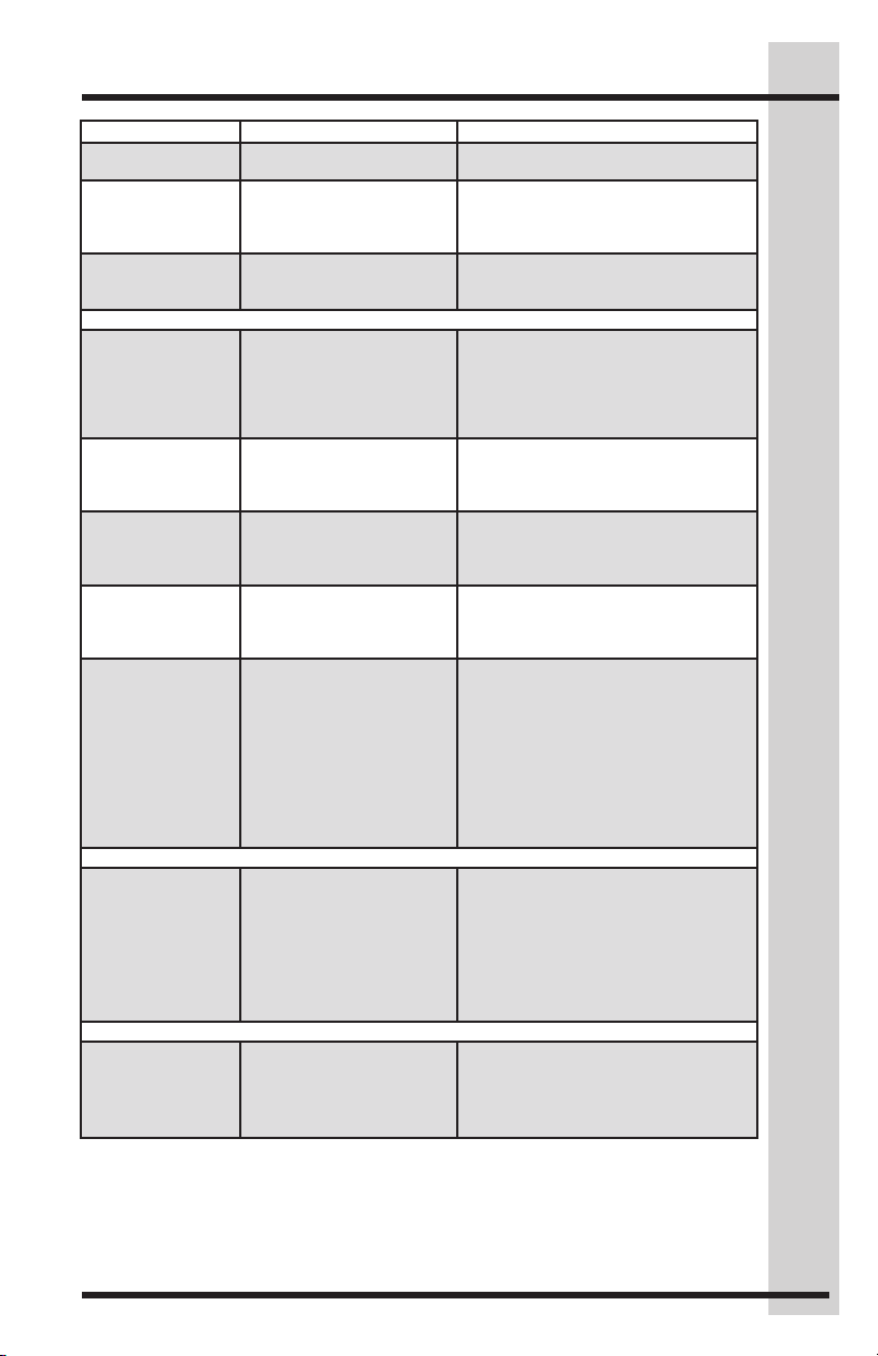
Solutions to Common Problems
Concern Potential Cause Common Solution
“LO” is displayed
on control.
“E7”, “E8”, “E9”
is displayed on
control.
“Sb” is displayed
on control.
Sound & Noise
Louder sound
levels whenever
appliance is on.
Louder sound
levels when
compressor
comes on.
Popping or
cracking sound
when compressor
comes on.
Bubbling or
gurgling sound.
Vibrating or
rattling noise.
Water / Moisture / Frost Inside Refrigerator
Moisture forms
on inside
appliance walls
Odor In Appliance
Odors in
appliance.
• Control has been locked. • Press the CONTROL LOCK key
• The control has
registered an error code.
• The control is in
Sabbath Mode.
• Modern appliances
have increased storage
capacity and more
stable temperatures.
They require heavyduty compressors.
• Appliance operates at
higher pressures during
the start of the ON cycle.
• Metal parts undergo
expansion and
contraction, as in hot
water pipes
• Refrigerant (used to
cool appliance) is
circulating throughout
the system.
• Appliance is not level. It
rocks on the floor when
it is moved slightly.
• Floor is uneven or weak.
• Appliance is touching
the wall.
• Weather is hot
and humid, which
increases internal rate
of frost buildup.
• Door is slightly open.
• Door is kept open too
long or is opened too
frequently.
• Interior needs to be
cleaned.
• Foods with strong odors
are in the appliance.
for 3 seconds to unlock.
• For toll-free telephone support
in the U.S. and Canada:
1-877-4ELECTROLUX (1-877435-3287)
• Pressing the CONTROL LOCK
and TEMP MODE keys to exit
Sabbath Mode.
• This is normal. When the
surrounding noise level is low,
you might hear the compressor
running while it cools the interior.
• This is normal. Sound will level
off or disappear as appliance
continues to run.
• This is normal. Sound will level
off or disappear as appliance
continues to run.
• This is normal.
• Level the appliance. Refer to the
LEVELING section.
• Ensure floor can adequately
support the appliance. Level the
appliance by putting wood or metal
shims under part of the appliance.
• Re-level appliance or move
appliance slightly. Refer to the
LEVELING section.
• This is normal.
• See “DOOR PROBLEMS”.
• Open the door less often.
• Clean interior with sponge, warm
water, and baking soda. Replace
air filter.
• Cover the food tightly.
21
Page 22
22
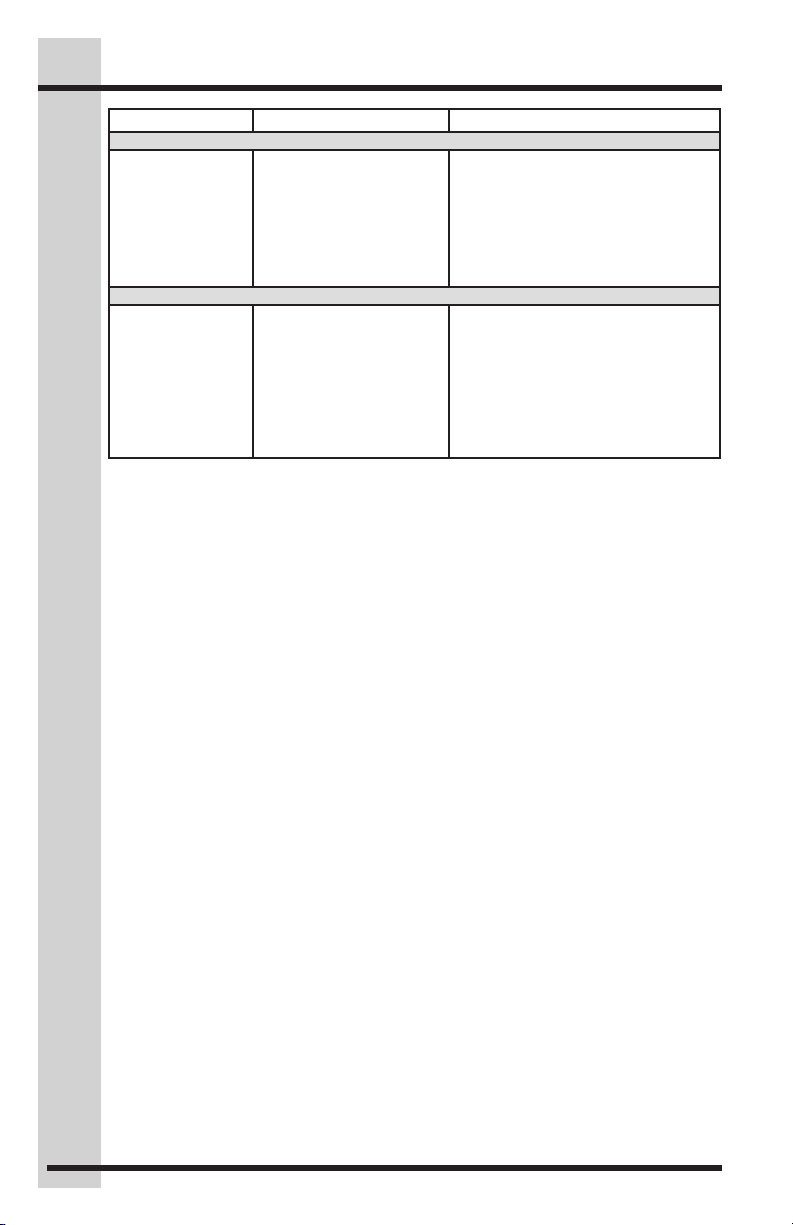
Solutions to Common Problems
Concern Potential Cause Common Solution
Door Problems
Door will not
close.
Lighting Problems
Light bulb is not on.
• Appliance is not level. It
rocks on the floor when
it is moved slightly.
• Floor is uneven or weak.
• The LED or light bulb is
burned out.
• No electric current is
reaching the appliance.
• Control is in Sabbath
mode (Sb is displayed
on control)
• This condition can force the cabinet
out of square and misalign the door.
Refer to the “LEVELING” section.
• Ensure floor can adequately
support appliance. Level the
appliance by putting wood or
metal shims under part of the
appliance.
• Follow directions under the
“Theater™ LED Lighting” section.
• See “APPLIANCE DOES NOT RUN”.
• Depress TEMP MODE key and
CONTROL LOCK key for
3 seconds.
Page 23
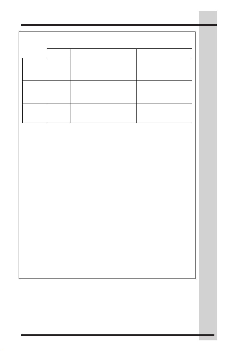
Major Appliance Warranty Information
REFRIGERATOR WARRANTY Your refrigerator is protected by this warranty
WARRANTY
PERIOD
THROUGH OUR AUTHORIZED SERVICERS,
WE WILL:
THE CONSUMER WILL BE
RESPONSIBLE FOR:
FULL ONE-
One year from
Pay all costs for repairing or replacing any pa rts of
warranted for 30 days (part s only).
Costs of service calls that are listed under
LIMITED 2nd– 5TH
System)
Second through
Repair or replace any parts in the cabinet lin er or
Costs for pickup and delivery of the
LIMITED
Alaska)
Time periods
All of the provisions of the full warranties above
Costs of the technician's travel to the
In the U.S.A., your appliance is warranted by Electrolux Home Products, Inc. We authorize no person to change or add to
Canada Corp.
*NORMAL
This warranty applies only to products in ordinary household use, and the consumer is
replacement of blown
Expenses for making the appliance accessible for servicing, such as removal of trim,
6. Replacement of light bulbs and/or fluorescent tubes (on models with these features).
EXCLUSIONS
This warranty does not cover the following:
PERTY DAMAGE AND
INCIDENTAL EXPENSES RESULTING FROM ANY BREACH OF THIS WRITTEN OR ANY
determined.
IF YOU NEED
Keep your bill of sale, delivery slip, or some other appropriate payment record. The date on the
obtained by contacting Electrolux Home Products, Inc. or Electrolux Canada Corp.
This warranty only applies in the 50 States of the U.S.A. and Puerto Rico, and Canada. Product features or specifications
Inc. In Canada, your appliance is warranted by Electrolux Canada Corp.
USA
Canada
L5V 3E4
23
original
purchase date.
fifth years from
original
purchase date.
listed above.
YEAR
WARRANTY
YEAR
WARRANTY
(Cabinet Liner
and Sealed
WARRANTY
(Applicable to
the State of
any of our obligations under this warranty. Our obligations for service and parts under this warranty must be performed by
us or an authorized Electrolux Home Products, Inc. servicer. In Canada, your appliance is warranted by Electrolux
RESPONSIBILITIES
OF THE
CUSTOMER
this appliance which prove to be defecti ve in
materials or workmanship. Excludes original and
replacement Ice & Water filt er cartridges (if
equipped). Original and re placement cartridges are
sealed refrigeration system (compressor,
condenser, evaporator, dryer or tubing) which
prove to be defective in ma terials or workmanship.
and the exclusions listed below apply.
responsible for the items listed below:
1. Proper use of the appliance in accordance with instructions provided with the product.
2. Proper installation by an authorized servicer in accordance with instructions provided with the
appliance and in accordance with all local plumbing, electrical and/or gas codes.
3. Proper connection to a grounded power supply of sufficient voltage,
fuses, repair of loose connections or defects in house wiring.
4.
cupboards, shelves, etc., which are not a part of the appliance when i t was shipped from the
factory.
5. Damages to finish after installation.
NORMAL RESPONSIBILITIES OF THE
CONSUMER.*
appliance required becaus e of service.
Costs for labor, parts and transportatio n
other than with respect to the cabinet liner
or Sealed Refrigeration System.
home and any costs for pick up and
delivery of the appliance required bec ause
of service.
1. CONSEQUENTIAL OR INCIDENTAL DAMAGES SUCH AS PRO
IMPLIED WARRANTY.
Note: Some states do not allow the exclusion or limitation of incident al or consequential
damages, so this limitation or exclusion may not apply to you.
2. Service calls which do not involve malfunction or defects in workmanship or material, or for
appliances not in ordinary household use. The consumer shall pay for such service calls.
3. Damages caused by services performed by servicers other than Electrolux Home Products,
Inc., Electrolux Canada Corp., or its authorized servicers; us e of parts other than genuine
Electrolux Home Products parts; obtained from persons other than such servicers; or ex ternal
causes such as abuse, misuse, inadequate power supply or acts of God.
4. Products with original serial numbers that have been removed or altered and cannot be readily
SERVICE
as described or illustrated are subject to change without notice. All warranties are made by Electrolux Home Products,
bill establishes the warranty period should service be required. If service is performed, it is in your
best interest to obtain and keep all receipts. This written warranty gives you specific legal rights.
You may also have other rights that vary from state to state. Service under this warranty must be
877-435-3287
Electrolux Home Products, Inc.
10200 David Taylor Drive
Charlotte, NC 28262
Electrolux Canada Corp.
5855 Terry Fox Way
Mississauga, Ontario, Canada
1-800-265-8352
Page 24

 Loading...