

Page 1
Installation and service must be pefformed byaqu , i lstaller.
IMPORTANT: Save for local electrical inspector s use,
Read and Save these instructions for future
Th e e lectricalreq u ire m ents fo r t his ova n a re 120vo Itsi 15 a rnps!
NOTE
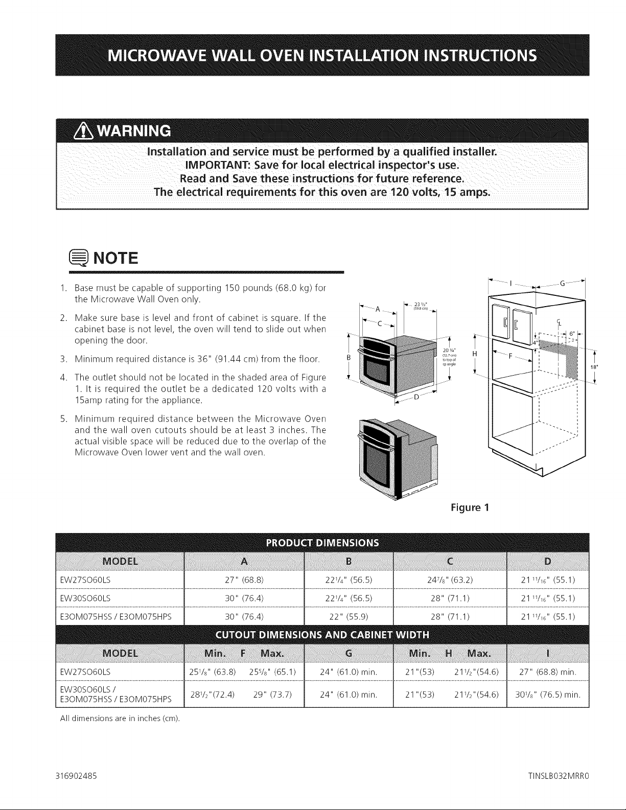
Base must be capable of supporting 150 pounds (68.0 kg) for
the Microwave Wall Oven only.
2,
Make sure base is level and front of cabinet is square. If the
cabinet base is not level, the oven will tend to slide out when
opening the door.
3,
Minimum required distance is 36" (91.44 cm) from the floor.
4.
The outlet should not be located in the shaded area of Figure
1. It is required the outlet be a dedicated 120 volts with a
15amp rating for the appliance.
5,
Minimum required distance between the Microwave Oven
and the wall oven cutouts should be at least 3 inches. The
actual visible space will be reduced due to the overlap of the
Microwave Oven lower vent and the wall oven.
Figure I
EW27SO60LS 27" (68.8) 22%" (56.5) 247/8"(63.2) 21 W_G"(55.1)
EW3OSO6OLS 30" (76.4) 22V4" (56.5) 28" (71.1) 21 W_G"(55.1)
E30MO75HSS / E30MO75HPS
EW3OSO6OLS /
E30MO75HSS / E30MO75HPS
All dimensions are in inches (cm).
316902485 TINSLBO32MRRO
28%"(72.4) 29" (73.7) 24" (61.0)min. 21"(53)
30" (76.4) 22" (55.9)
28" (71.1) 21 W_G" (55.1)
21V2"(54.6) 30V8" (76.5) min.
Page 2

iMPORTANT NOTES TO
iMPORTANT SAFETY
THE iNSTALLER
,
Read all instructions contained in these installation
instructions before installing the Microwave Wall Oven.
This oven can be built into a cabinet or wall by itself or
above any electric wall oven or warming drawer.
,
Remove all packing material from inside the oven cavity
before connecting the electrical supply to the Microwave
Wall Oven. DO NOT REMOVETHE WAVEGUIDE COVER,
which is located on the cavity ceiling. See Figure 2A.
Waveguide Cover
Oven Cavity
Door Seals
and Sealing
Surfaces
Hinge
Safety
Door Latch
Figure 2A Figure 2B
iNSTRUCTiONS
ventilation can be dangerous.
Carpentry
Refer to Figure 1 for the dimensions required for your
appliance, and the space necessary to install the oven. The
oven support surface should be solid plywood or similar
material, the surface must be level from side to side and
from front to rear.
Electrical Requirements
The appliance operates on a 120 volt, 60 Hz electrical
supply with a separate ground wire. Provide a separate
circuit with a fuse or circuit breaker rated for 15 amps.
Observe all governing codes and local ordinances
,
Remove the 2 shipping duct supports (see Figure 2B)by
removing the 2 screws securing each side. Reinsert 2
screws (each side) to secure the stainless cover.
,
Remove the feature sticker, if there is one, from the
outside of the door.
,
Check the oven for any damage, such as misaligned or
bent door, damaged door seals and sealling surfaces,
broken or loose door hinges and latches and dent
inside the cavity or on the door.
AUTHORIZED SERVICER
6. Observe all governing codes and local ordinances.
7. Be sure to leave these instructions with the consumer.
iMPORTANT NOTE TO
THE CONSUMER
Keep these instructions with your Owner's Guide for future
reference.
T0p"event damage to the oven contio!: duiing _old
ternperature weather, wait at least three (3)hours
after receiying this oven before supplyieg power to
the appliance. Thiswill prevent possibledamage to the
buiBin ovencontrol at power on.
Cabinet Installation
The Mkrowave Wall oven can tip when the door
is openl The Anti-Tip brackets supplied with th e
Microwave Wall Oven must be attached to the
cabinet and the appliance t0 prevent tipping of
the unit and injury to persons;
ANTI41P BRACKETS INSTALLATION
INSTRUCTIONS
Unpack the Microwave Wall Oven and find the 2
Anti-Tip brackets and screws included in the literature
package.
,
Install the Anti-Tip bracket in the cabinet as shown
on Figure 3. Note: To prevent damage to cabinet, it
is recommended to drill 1/16"(0.16 cm) diameter pilot
holes before installing the Anti-Tip brackets.
E2
Page 3
MICROWAVE WALL OVEN iNSTALLATiON
hold the door handle when moving the oven.
,
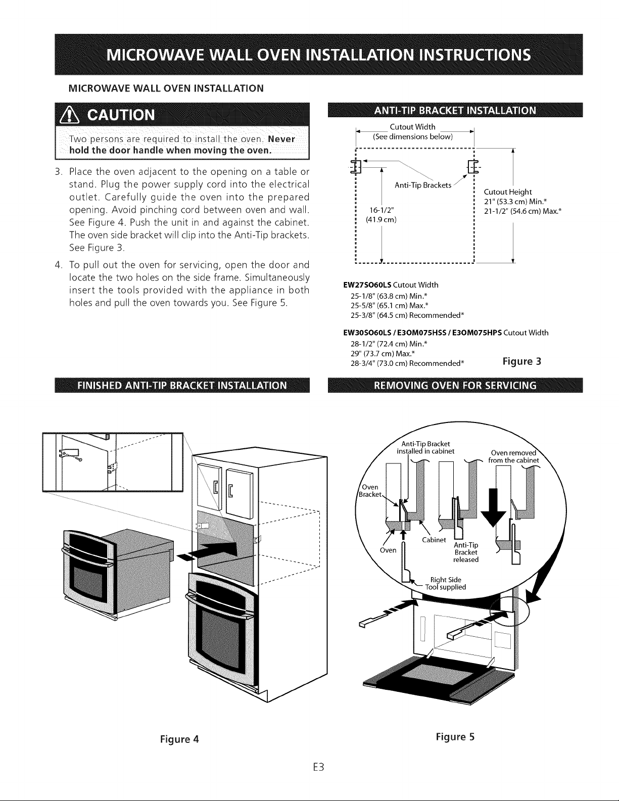
Place the oven adjacent to the opening on a table or
stand. Plug the power supply cord into the electrical
outlet. Carefully guide the oven into the prepared
opening. Avoid pinching cord between oven and wall.
See Figure 4. Push the unit in and against the cabinet.
The oven side bracket will clip into the Anti-Tip brackets.
See Figure 3.
,
To pull out the oven for servicing, open the door and
locate the two holes on the side frame. Simultaneously
insert the tools provided with the appliance in both
holes and pull the oven towards you. See Figure 5.
Cutout Width
(See dimensions below)
ckets j
16-1/2"
(41.9 cm)
Cutout Height
21" (53.3 cm) Min.*
21-1/2" (54.6 cm) Max.*
/
EW27SO60LS Cutout Width
25-1/8" (63.8 cm) Min.*
25-5/8" (65.1 cm) Max.*
25-3/8" (64.5 cm) Recommended*
EW3OSO6OLS / E30MO75HSS / E30MO75HPS Cutout Width
28-1/2" (72.4 cm) Min.*
29" (73.7 cm) Max.*
28-3/4" (73.0 cm) Recommended* Figure 3
Figure 4 Figure 5
E3
Page 4

Model and Serial Number Location
Before You Call for Service
The serial plate is located on the oven front frame. See
Figure 6.
When ordering parts for or making inquires about your
oven, always be sure to include the model and serial
numbers and a lot number or letter from the serial plate on
your oven.
Serial
Plate
Menu
Label
Figure 6
Refer to the warranty in your Use & Care Guide for our
toll-free service number and address. Please call or write
if you have inquiries about your product and/or need to
order parts.
E4
Page 5

Un installateur qualifi_ doit proc_der_I!installation et aux reparationsi
IMPORTANT:Conserver_ Iiusaged'un inspecteuren @lectridt@local:
Life et conservercesdirectives pour referencefuture,
L alimentation _lectrique pour ce four est de 120 v01tS CA, 15 amperes et plusl J
REIVlARQUES
La base doit pouvoir supporter 68,0 kg (150 Ib) pour le four a
micro-ondes mural seul.
2,
Veiller a ce que la base soit horizontale et I'avant de I'armoire
perpendiculaire. Si la base de I'armoire n'est pas horizontale, le
four aura tendance a glisser Iors de I'ouverture de la porte.
3,
Distance minimale requise du plancher est de 91,44 cm (36 po).
4.
La prise NE doit PAS se trouver dans I'aire ombr_e comme
indiqu_ a la Figure 1. IIest excessivement important que la prise
soit de 120 volts et 13 amperes pour une performance optimale
du four.
5,
La distance minimale exigee entre le four a micro-ondes et les
d_coupes du four mural doit 6tre de 7,62 cm (3 po). Le visible
espace sera reduit en raison de la superposition de la moindre
ventilation Four a micro-ondes et le mur four.
llP°
Toutes les dimensions sont en centim_tres (po).
Figure I
F1
Page 6

NOTES IMPORTANTES
IMPORTANTES CONSIGNES
POUR L'iNSTALLATEUR
1. Lire toutes lesdirectives d'installation avant d'installer le
four _ micro-ondes mural. Votre four peut _tre install_
dans une armoire, contre un mur, au-dessus d'un four
_lectrique mural ou d'un tiroir chauffe-plat.
2. Retirer tousles mat_riaux d'emballage de la cavit_ du
four avant de le connecter au secteur. NE PAS RETIRER
LE COUVERCLE DU GUIDE D'ONDES, situ_ contre la
paroi sup_rieure de la cavitY. Voir Figure 2A.
Couvercle du
Guide d'ondes
Four cavit_
Joints
d'6tanch_it_
et port_es
des joints
Charni@res
Verrous
Figure 2A Figure 2B
DE SECURITE
Ne jamais utiliser votre four _ micro-ondes mural
pour chauffer une pi@ce. II peut _tre dangereux
d'utiliser le four sans ventilation adequate pendant
une Iongue p_riode.
Menuiserie
Se reporter a la Figure 1 pour les dimensions applicables
votre appareil eta I'espace n@cessairepour le recevoir. La
surface supportant le four peut _tre du contreplaqu@ plein
ou un mat@riausemblable; elle doit _tre horizontale.
Alimentation l lectrique
Cet appareil doit recevoir une tension et fr_quence adequate,
et _tre connect_ _ un circuit individuel correctement mis
la terre, prot_g_ par un disjoncteur ou un fusible de la
bonne intensitY.
Observer tousles codes et r_glernents Iocaux en
vigueur.
3. Enlever les deux supports d'exp_dition des conduits
(Voir Figure 2B) en retirant les 4 vis qui lesfixent. Reposer
2 vis (de chaque c6t_) pour fixer le couvercle en inox.
4. Retirer, s'il y en a une, I'_tiquette autocollante des
caract_ristiques sur I'ext_rieur de la porte.
,
V_rifier que le four n'a subi aucun dommage, en
particulier que la porte n'est ni tordue ni d_centr_e,
que les joints et les surfaces d'_tanch_it_ ne sont pas
endommag_s, que les charni_res et les verrous ne sont
pas bris_s ou desserr_s et que la porte ou I'int_rieur de
la cavit_ ne porte aucune trace de coups.
: ELECTROLUXAUTORISE.
6. Observer tousles codes et r_glements en vigueur.
7. Veiller _ laisser ces directives au client.
NOTES IMPORTANTES
AU CLIENT
Conserver ces instructions avec votre guide du propri_taire
pour r_f_rence ult_rieure.
p0ur _viter d'endommager lescomrnandesdu fouri par I
temps fE0id' attendre au m0ins trOiS (3)heureS ap[eS I
la r_ception du four avant de le mettre sous tensio n.
Cela emp6¢hera d'end0mmager _ventue!lement !es I
commandesint_gr_es du four: I
Pose dans I'armoire
Le four _ micro-ondes mural peut basCuler I
quand lap0rt eest0uverte:llfautfixer esbrides I
antibascu!ement fournies avec le four a i
et _ I appareil pour emp@cher qu il ne bascule et I
blesse des personnesl
DIRECTIVES D'INSTALLATION DES BRIDES
ANTIBASCULEMENT
D_baller le four a micro-ondes mural et trouver les 2
brides antibasculement et les vis jointes a I'emballage
de documents.
,
Poser les brides antibasculement dans I'armoire comme
illustr_ a la Figure 3. Note : Pour _viter d'endommager
I'armoire, il est recommand_ de percer desavant-trous de
1/16 po (0,16 cm) de diametre avant de poser les brides.
F2
Page 7

iNSTALLATiON DU FOUR A MiCRO-ONDES MURAL
Ne jamais tenir la poign_e de !a poite en d6plac_ant le
four: II faut deux personnes pour installer le four.
.
Placer le four pros de I'ouverture sur une table ou
un support. Brancher le cordon d'alimentation dans
la prise _lectrique. Guider avec precaution le four
assembl_ dans I'ouverture pr_par_e, t_viter de pincer le
cordon entre le four et le tour. Voir Figure 4. Pousser
I'appareil dans et contre I'armoire. La bride lat_rale du
four s'enclenchera dans les brides antibasculement. Voir
Figure 3.
.
Pour retirer le four en cas de r_paration, ouvrir la
porte et rep_rer les deux trous dans le chassis lateral.
Simultan_ment insurer les outils fournis avec I'appareil
dans lesdeux trous et tirer lefour vers vous. Voir Figure 5.
Dimensions de la d_coupe
(Voir dimensions ci-dessous)
r ..........
=
-_Bl°c_lement _-Dimensions
de la D_coupe
41,9 cm 53,3 cm (21 po) Min. _
(161/2 po) 54,6 cm (211/2 po) Max. _
EW27SO60LS
Dimensions de la d_coupe
63,8 cm (25-1/8 po) Min. _
65,1 cm (25-5/8 po) Max. _
64,5 cm (25-3/8 po) Recommand_ _
EW3OSO6OLS / E30MO75HSS / E30MO75HPS
Dimensions de la d_coupe
72.4 cm (28-1/2 po) Min. _
73.7 cm (29 po) Max. _
73.0 cm (28-3/4 po) Recommand_ _
Figure 3
Figure 4 Figure 5
F3
Page 8

Emplacement des nurneros de
rnodele et de serie
La plaque de serie est situee sur la faqade du four. Voir
Figure 6.
Lots de la commande de pieces ou de la demande
d'information sur lefour, veiller a toujours inclure le numero
de mod61e et les numeros de serie et un numero ou une
lettre de lot situes sur la plaque de serie de votre four.
Plaque
de s@ie
etiquette
menu
Avant d'appeler le service de
reparations
Vous trouverez le numero de service sans frais et I'adresse
pour la garantie dans votre mode d'emploi et d'entretien.
Veuillez appeler ou ecrire si vous avez des questions au
sujet de votre produit ou si vous avez besoin de commander
des pieces.
Figure 6
F4
Page 9

La instalaci6n y el servicio deben ser realizados pot un instalador calificadoi
IMPORTANTE: Guarde para uso del inspector el_ctrico Iocali
Lea y guarde estas instrucciones para
Los requisitos el@ct_ricos de este homo son de 120 v01tios de CA; 15 amperios o masl
NOTA
La base debe poder soportar 150 libras (68.0 Kg.)
........ G ...... 1
correspondientes s61o al homo microondas de pared.
2,
AsegOrese de que la base este nivelada y la parte frontal
del gabinete sea cuadrada. Si la base del gabinete no est,1
nivelada, el homo podrfa deslizarse al abrir la puerta.
3,
La distancia mfnima requerida es de 36" (91.44 cm) desde el
piso.
4,
Este tomacorriente no debe estar ubicado en el _irea
sombreada de la Figura 1. Es sumamente importante que
el tomacorriente sea de 120 voltios y 13 amperios para el
6ptimo funcionamiento del homo.
5,
La distancia mfnima requerida entre el Homo microondas y el
recorte del homo de pared debe ser al menos de 3 pulgadas.
El espacio real visibles se reducir_i debido a la superposiciOn
de la abertura inferior del homo de microondas y el homo de
pared.
Figura I
EW27SO60LS 27" (68.8) 22_A'' (56.5) 247/8"(63.2) 21 W16" (55.1)
EW30SO60LS 30" (76.4) 22V4" (56.5) 28" (71.1) 21 W16" (55.1)
E3OMO75HSS/E3OMO75HPS 30" (76.4) 22" (55.9) 28" (71.1) 21 W16" (55.1)
EW27SO60LS 25V8" (63.8) 256/8'' (65.1) 24" (61.0) min. 21"(53) 21V2"(54.6) 27" (68.8) min.
EW3OSO6OLS/
E30MO75HSS/ E30MO75HPS 2@/2"(72.4) 29" (73.7) 24" (61.0)rain. 21"(53) 21V2"(54.6) 3@/8" (76.5)rain.
Todas las dimensiones est_in en pulgadas (cm).
$1
Page 10

NOTAS IMPORTANTES
INSTRUCCIONES DE
PARA EL INSTALADOR
1. Lea todas las instrucciones contenidas en estas instrucciones
de instalaciOn antes de realizar la instalaciOn del Homo
microondas de pared. Su homo puede ser empotrado
dentro de un gabinete o pared por s[ mismo o encima de
cualquier homo de pared electrico o caj6n calentador.
2. Retire todos los materiales de embalaje de la cavidad del
homo antes de conectar el suministro el_ctrico al Homo
microondas de pared. NO RETIRE LA CUBIERTA DE LA
GUfA DE ONDA, que esta ubicada en el techo de la
cavidad. Vea la Figura 2A.
Guia de onda
Homo de
Cavidad _
Sellos y
superficies
de sellado
Bisagras
Pestillos
de la puerta
3.
4.
5.
Figura 2A Figura 2B
Retire los 2 soportes de embarque para ducto (vea la
Figura 2B) retirando los 4 tornillos que los aseguran.
Reinstale los 2 tornillos (en cada lado) para asegurar la
cubierta inoxidable.
Retire cualquier etiqueta adhesiva que encuentre en
la parte exterior de la puerta.
Revise que el homo no tenga daflos como puertas
torcidas o mal alineadas, sellos de puerta y superficies
del cierre hermetico daflado, bisagras y pestillos rotos
o flojos y abolladuras en la cavidad o en la puerta. Si
encuentra algOn daflo, no haga funcionar el horno
y comun[quese con su distribuidor o PERSONAL DE
SERVlCIO AUTORIZADO DE ELECTROLUX.
[
SEGURIDAD IMPORTANTES
Nunca use el Homo microondas de pared para subir
la temperatura de la habitaci6n. El uso prolongado
del homo sin ventilaciOn adecuada puede ser peligroso.
Carpinteria
Consulte la Figura 1 para las dimensiones que se aplican a su
artefacto, y el espacio necesario para el homo. La superficie
de soporte de homo puede ser de un material solido como
madera laminada o similar, sin embargo la superficie debe estar
nivelada de lado a lado y desde la parte frontal hasta la parte
posterior.
Requisitos electricos
Este artefacto debe recibir un suministro el_ctrico con el voltaje
y frecuencia apropiados, y estar conectado correctamente a
tierra a un circuito independiente y protegido por un interruptor
autom_itico o fusible con el amperaje adecuado.
Respete todos los c6digos y normas vigentes
Para evitar dahoS ai controi del hornOi durante los €limas
de bajas temperaturas, espe:e al menos tres (3) bolas
despu_s de recibir este homo antes de encenderlo. Esto
evitar_i posibles da_os al control del horno incorporado
cuando Io encienda.
Instalaci6n en gabinete
El Homo rnicroondas de pared puede volcarse
al abrir la puerta. Los soportes antivuelco
suministrados con el Homo microondas de pared
deben set instalados en el gabinete y el artefacto
para evitar la volcadura de la unidad y las lesiones
a las personas.
ELECTROLUX AUTHORIZED SERVICER:
6. Respete todos los codigos y normas vigentes.
7. Aseg0rese de proporcionar estas instrucciones al
consumidor.
NOTA IMPORTANTE PARA
EL CONSUMIDOR
Guarde estas instrucciones con la Gu[a del usuario para
consultas posteriores.
INSTRUCCIONES DE INSTALACION DE LOS
SOPORTES ANTIVUELCO
Desempaque el Homo microondas de pared y Iocalice
los 2 soportes antivuelco y los tornillos incluidos en el
paquete de materiales informativos.
2.
Instale el soporte antivuelco en el gabinete como se
muestra en la Figura 3. Nota: Para evitar dahos en el
gabinete, se recomienda perforar agujeros gu[a de 1/16"
(0.16 cm) de di_imetro antes de instalar los soportes.
$2
Page 11

INSTALAClON DEL HORNO MICROONDAS DE PARED
para instalar el homo
Ancho de corte
(Ver dimensiones m_s abajo)
r ..............
u u
m
3. Coloque el horno al lado de la abertura sobre una
mesa o base. Conecte el cable de alimentacion en el
tomacorriente el_ctrico. Gufe con cuidado el horno
dentro de la abertura preparada. Evite que el cable
quede presionado entre el horno y la pared. Vea la Figura
4. Empuje la unidad dentro y hacia el gabinete. El lado
con soporte del horno se enganchara en los soportes
antivuelco. Vea la Figura 3.
4. Para retirar el homo para su reparaciOn, abra la puerta
y ubique los dos agujeros en el marco lateral. Inserte
simultaneamente las herramientas proporcionadas con el
artefacto en ambos agujeros y jale el horno hacia usted.
Vea la Figura 5.
_ridesAntibasculement
16-I/2"
(41.9cm)
EW27SO60LS Ancho de corte
25-I/8" (63.8 cm) Min.*
25-5/8" (65.1 cm) Max.*
25-3/8" (64.5 cm) Recomendado*
EW3OSO6OLS / E30MO75HSS / E30MO75HPS Ancho de corte
28-1/2" (72.4 cm) Min.*
29" (73.7 cm) Max.*
28-3/4" (73.0 cm) Recomendado* Figura 3
Altura corte
21" (53.3 cm) Min.*
21-I/2" (54.6 cm) Max.*
Figura 4
Figura 5
$3
Page 12

Ubicad6n del numero del modelo y
de serie
La placa con n0mero de serie est,1ubicada sobre la placa
frontal del homo. Vea la Figura 6
AI ordenar partes de reemplazo o hacer preguntas sobre su
homo, no olvide incluir los n0meros del modelo y de serie
y el n0mero de Iote o letra de la placa con n0mero de serie
de su homo.
Etiqueta
del Serial
Etiqueta
menu
Antes de solicitar servicio
Consulte sobre la garantfa en su Gufa de uso y cuidado
para ubicar nuestro telefono gratuito para servicio y la
direccion. Llame o escrfbanos si tiene alguna duda sobre su
producto y/o necesite ordenar partes de reemplazo.
Figura 6
$4
 Loading...