

Electrolux DIVA Series Service Manual
SOI/TD 1/23 599 37 44-27
SERVICE MANUAL
DISHWASHERS
E.M.A. - Europe
Spares Operations Italy
Corso Lino Zanussi,30
Publication no.
I - 33080 PORCIA /PN (ITALY)
599 37 44-27
Fax +39 0434 394096
Edition: 2005-12
EN
“DIVA”
DISHWASHERS
60 cm PNC 911 5.. …
ACCESSIBILITY
Production:
PLV – Zarow (Poland)

SOI/TD 2/23 599 37 44-27

SOI/TD 3/23 599 37 44-27
CONTENTS:
1
ACCESSIBILITY.....................................................................................................................................4
1.1 To access the components from above, first remove the worktop (free-standing versions only):..4
1.2 To access the components housed in the base from the front of the appliance (free-standing
versions):....................................................................................................................................................4
1.3 To access the components housed in the base from the lower section, remove the bottom panel
(if featured) as follows:...............................................................................................................................4
1.4 To access components from the side, remove the relative lateral panel:.......................................5
2 STRUCTURAL CHARACTERISTICS ....................................................................................................5
2.1 Door area ........................................................................................................................................6
2.2 Base area ........................................................................................................................................6
2.3 Tub area ..........................................................................................................................................7
3 Open the door to access the following: ..................................................................................................7
3.1 Central drain filter............................................................................................................................8
3.2 Large washing filter .........................................................................................................................8
3.3 Lower spray arm .............................................................................................................................8
3.4 Upper spray arm and duct...............................................................................................................8
4 Access from above .................................................................................................................................9
4.1 Drying duct/fan (if featured).............................................................................................................9
5 Access from the front..............................................................................................................................9
5.1 Sliding guide for upper basket.........................................................................................................9
5.2 Control panel assembly...................................................................................................................9
5.2.1 PCB .........................................................................................................................................10
5.3 External door.................................................................................................................................11
5.4 Beam on floor (fully-integrated versions only, if featured) ............................................................11
5.5 Inner door ......................................................................................................................................11
5.6 Latch assembly .............................................................................................................................12
5.7 Integrated dispenser .....................................................................................................................12
5.8 Thermostat/temperature and turbidity control sensor ...................................................................13
5.9 Regeneration solenoid valve.........................................................................................................13
5.10 Salt sensor (if featured)................................................................................................................13
5.11 Drain pump non-return valve........................................................................................................14
5.12 Internal feed manifold to the upper spray arm ..............................................................................14
6 Access from the base ...........................................................................................................................15
6.1 Anti-flooding device (if featured) ...................................................................................................15
6.2 Adjustable rear foot (built-in versions only)...................................................................................15
6.3 Sump assembly.............................................................................................................................15
6.4 Water softening system.................................................................................................................16
6.5 Drain pump....................................................................................................................................16
7 Access from the sides ..........................................................................................................................17
7.1 Washing motor capacitor ..............................................................................................................17
7.2 Supports for upper basket wheels ................................................................................................18
7.3 Lateral uprights .............................................................................................................................18
7.4 Hinges and hinge springs..............................................................................................................18
7.5 Water fill tank.................................................................................................................................19
7.6 Washing motor ..............................................................................................................................19
7.7 Level/anti-overflow pressure switches and support ......................................................................20
7.8 Tube-enclosed heating element....................................................................................................20
7.9 Fill solenoid valve (if featured) ......................................................................................................21
7.10 Power cable and terminal block with integrated suppressor.........................................................21
7.11 Lower front cross-member ............................................................................................................21
7.12 Upper rear cross-member .............................................................................................................22
7.13 Upper front cross-member ............................................................................................................22
8 Replacing the tub..................................................................................................................................23
9 Replacing the base...............................................................................................................................23
Repairs to electrical appliances must be effected by qualified personnel only.
Before accessing internal components, remove the plug from the power socket.
SOI/TD 4/23 599 37 44-27
1 ACCESSIBILITY
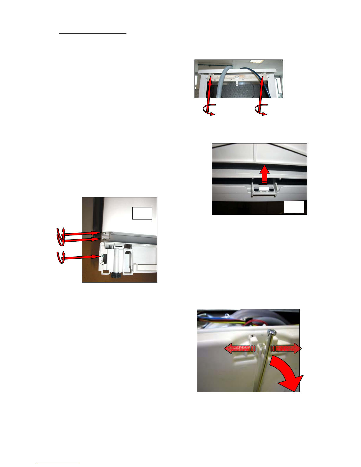
1.1 To access the components from above, first remove the worktop (free-standing
versions only):
(a) Remove the two screws from the rear section.
(b) Push the top forwards and release.
1.2 To access the components housed in the base from the front of the appliance
(free-standing versions):
(a) Remove the 5 lower plastic hooks starting from one side.
(b) Open the door to free the plinth.
(c) Rotate it and extract it.
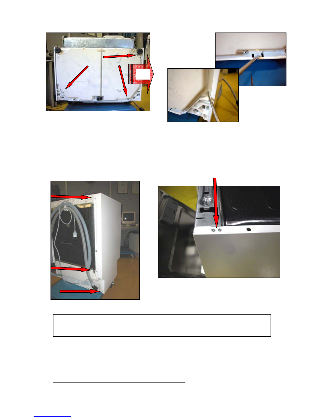
Foot support:
(d) Remove the 6 fixing screws and remove it paying
attention not to damage the external door.
1.3 To access the components housed in the base from the lower section, remove
the bottom panel (if featured) as follows:
(a) Remove the inner filters (see 3.1 and 3.2).
(b) Remove any residual water from the sump by
suction, so that it does not flow into the tub and the
pressure switch tubes, then lay the appliance on its
rear panel.
(c) Unscrew and remove the regulation screw from the
rear foot (built-in versions only).
(d) Remove the screws which secure the bottom panel
to the base).
(e) Release the built-in retaining elements placed on
the right and rear side: and remove the bottom
panel by sliding to the right.
( d)
( a)
(c)
SOI/TD 5/23 599 37 44-27
1.4 To access components from the side, remove the relative lateral panel:
(a) First remove the worktop (see 1.1), the plinth (free-standing versions) and the foot support (see 1.2).
(b) Remove the three rear screws, the upper and the lower front.
(c) Detach the lateral panel from the rear and slide away from the frontal anchor slot.
NB: Before laying the dishwasher on a side panel or on the rear panel
suck the water in the sump, for example by using a syringe, so as the
water does not reach the pressure switch tube or the tub.
2 STRUCTURAL CHARACTERISTICS
(d)
(c)
(e)

SOI/TD 6/23 599 37 44-27
The appliance may be considered as consisting of three major assemblies:
DOOR AREA - BASE AREA - TUB AREA
The entire structure is enclosed by a series of removable parts such as the worktop (free-standing versions
only), the door, two lateral panels, the plinth (free-standing versions only) and the foot support. Removal of
these parts facilitates access to the internal components from above, from the front, from the sides and from
the base of the appliance.
2.1 Door area
Control panel assembly
External door
Internal door
Hinge
Hinge pin
Lower door seal
Door latch assembly
Integrated dispenser
2.2 Base area
Base
Removable bottom panel (if featured)
Adjustable feet
Foot support
Adjustable rear foot (central) (built-in and fully-integrated versions)
Electronic board
Anti-flooding device (if featured)
Wash pump capacitor
Integrated terminal block/power cable/suppressor
Washing motor
Tube-enclosed heating element
Drain pump
Drain pump non-return valve
Fill solenoid valve (if featured)
Regeneration solenoid valve
Plinth (free-standing versions)
Water softening system
Salt sensor (if featured)
Level pressure switch
Anti-overflow pressure switch
SOI/TD 7/23 599 37 44-27
2.3 Tub area
Tub
Fitted externally to the tub:
Lateral uprights
Upper rear cross-member
Upper front cross-member
Lower front cross-member
Supports for upper basket wheels
External feed manifold to the upper spray arm
Sump assembly
Thermostat/temperature sensor + turbidity sensor
Water fill tank (short or long)
Drying duct/fan (if featured)
Fitted inside the tub:
Sliding guides for upper basket
Central drain filter
Large washing filter
Lower spray arm
Upper spray arm
Internal feed manifold to the upper spray arm
Upper/lower basket
Cap for water softening system
Steam venting ring
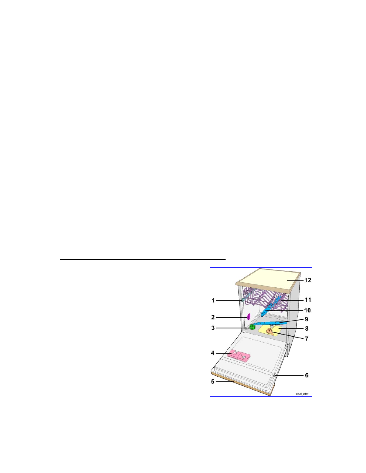
3 Open the door to access the following:
1.
Guides/wheel supports for upper basket
2.
Regulation knob for water softening system
3.
Salt reservoir cap
4.
Integrated detergent/rinse-aid dispenser
5.
Control panel assembly
6.
Serial number plate
7.
Central drain filter
8.
Large washing filter
9.
Lower spray arm
10.
Upper spray arm
11.
Upper/lower basket (*)
12.
Worktop (free-standing versions only)
(*) When replacing the EASY LIFT drum regulation assemblies, it is advisable to immerse them in hot water
for a few minutes, since they are easier to fit when softened.
 Loading...