

Electrolux Diva, Diva EDW 1500 Service Manual
SERVICE MANUAL
DISHWASHER
EDW 1500
+
© Electrolux
Muggenhofer Straße 135
D-90429 Nürnberg
Germany
Fax +49 (0)911 323 1022
Spares Operation
Ausgabe:
09.02
R.Kurzke
Publ.-Nr.:
599 515 015
EN
Dishwasher
+
EDW 1500

Index
1. Control panel ................................................................................... 3
2. Dimensions...................................................................................... 3
3. Components .................................................................................... 4
3.1 Electronic.........................................................................................4
3.2. Circulation pump .............................................................................4
3.3 Drain pump......................................................................................4
3.4 Flow heater...................................................................................... 4
3.5 Detergent dispenser ........................................................................ 5
3.6 NTC-thermal sensor ........................................................................ 6
3.7 Pressure switch ............................................................................... 6
3.8 Interference filter .............................................................................6
3.9 Spray arms ......................................................................................7
3.10 Drying fan ........................................................................................ 7
3.11 Regeneration dosing with condensor ............................................. 8
3.11.1 Water softening/regeneration .........................................................8
4. Repair informations ......................................................................... 9
4.1 Open the housing ............................................................................ 9
4.2 Position of the components ............................................................ 10 - 12
5. Water course Scheme .................................................................... 13
5.1 All-Around Water Protection ...........................................................14
5.2 Water intake .................................................................................... 15
5.2.1 Water load steps .............................................................................16 - 17
5.3 Draining ...........................................................................................18 - 19
6. Electronic......................................................................................... 20
6.1 In- and Output Elements .................................................................20
6.2 General information ........................................................................ 21
6.3 Input-philosophy: Program selection .............................................. 22
6.4 Input-philosophy: Select start time..................................................23
6.5 Input-philosophy: Program run........................................................ 24
6.6 Input-philosophy: Delete program...................................................25
6.7.1 Input-philosophy: Alter program ...................................................... 26
6.7.2 Input-philosophy: Alter program ...................................................... 27
6.8 Input-philosophy: Interrupt program................................................28
6.9 Input-philosophy: Displays ..............................................................29
6.10 Overview of service and customer support functions..................... 30
6.11 Setting of water hardness ............................................................... 31
6.12 Deactivation of rinse-aid addition....................................................32
6.13 Deactivation of signal sound ........................................................... 33
7.Service functions.............................................................................34
7.1 Fault memory / single actuator selection ........................................34
7.2 LED test ........................................................................................... 35
7.3 Manufacturing test routine ..............................................................36
7.4 Overview of error displays...............................................................37
8. Program steps ................................................................................. 38
9. Wirings ............................................................................................ 39
9.1 Circuit diagram ................................................................................ 39
9.2 Wiring diagramn .............................................................................. 40
09.2002 R.K. 599 515 015 EN
- 2 -
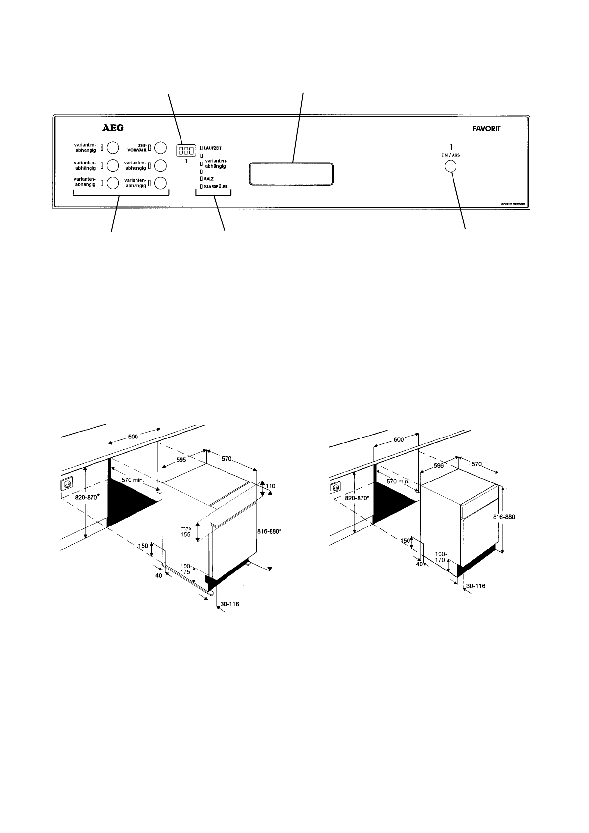
1. Control panel
Display
Control lamps
2. Dimensions
Build-in dimensions for Integrated
Dishwashers
Door handle
On/Off buttonProgamme buttons
Build-in dimensions for Built-Under
Dishwashers
ÖKO-FAVORIT
* Appliances with height-adjustable feet
Plinth height for appliances 820 mm high
100 - 175 mm
Plinth height for appliances 870 mm high
150 - 230 mm
ÖKO-FAVORIT
* Appliances with
height
adjustable feet
Dimensions for Freestanding Dishwasher
Height 85 cm
Width 60 cm
Depth 60 cm
Height with worktop removed 82 cm
Feet adjustment 1 cm
09.2002 R.K. 599 515 015 EN
- 3 -
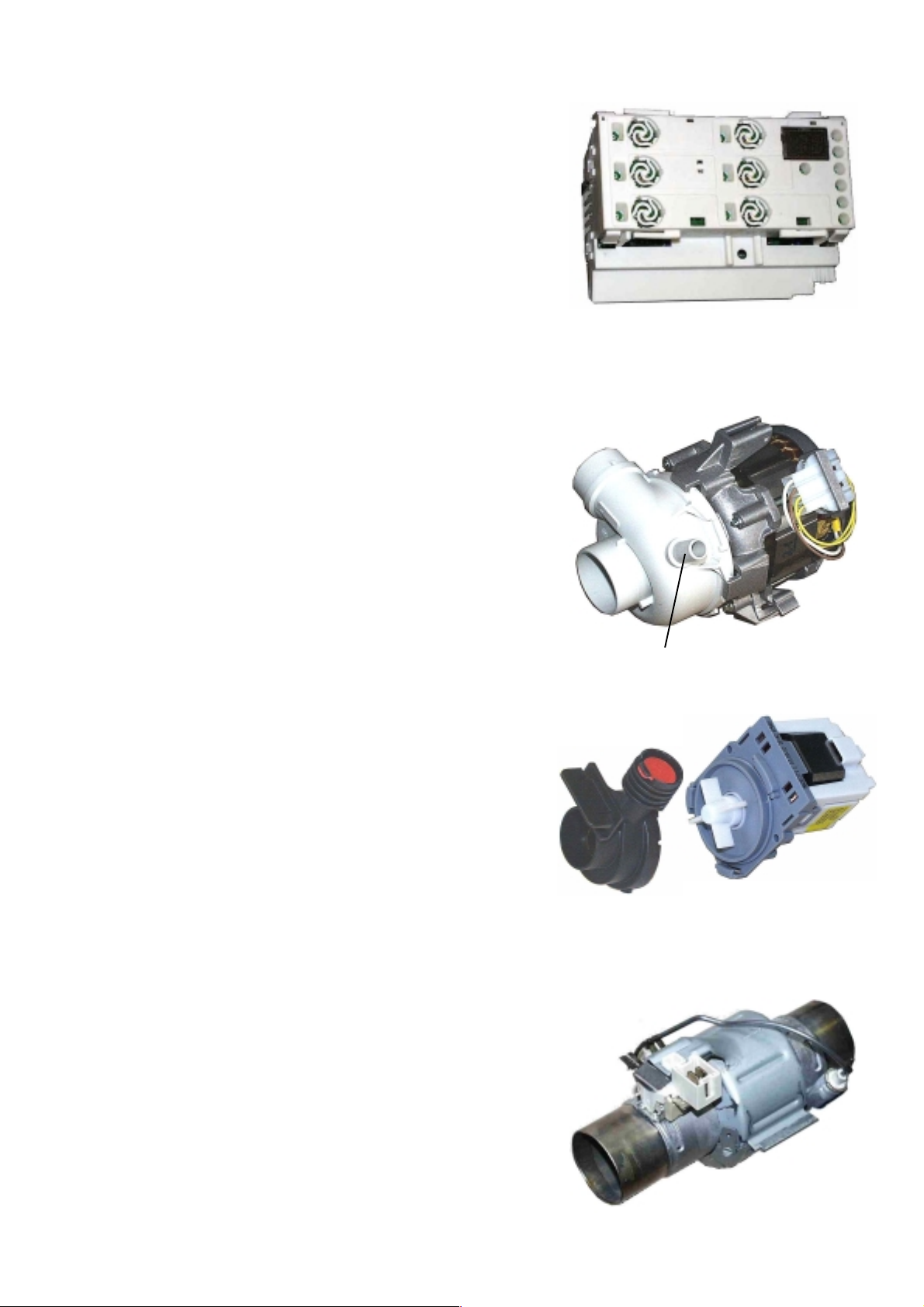
3. Components
3.1 Electronic
On electronic models, a micro processor controls all
components, this is done using triacs. The electronic also
memorizes all programme data.
The heating is switched by a relay on the electronic board.
3.2 Circulation Pump
The circulation pump is driven by an asynchronous motor with
an auxiliary winding. The auxiliary winding ist in circuit with a 3
mF capacitor. A tacho generator is used for speed control.
There are three speeds for rinsing.
2800 1/min, 2200 1/min, 1900 1/min, 1700 1/min, 1600 1/min,
Power output50 W.
Only for models with ceiling Sprayarm
3.3 Drain Pump
The drain pump is driven by a synchronous motor.
Power output 26 W.
Pump rate 15 l/min.
3.4 Flow Heater
The flow heater heats the water to the required temperature.
During the wash cycle, water is contantly passing through the
flow heater.
Power output 2000 W
Resistor 25 W
Protector 98 °C ± 5 K
Thermal fuse 260 °C
05.2002 R.K. 599 514 DE
- 4 -
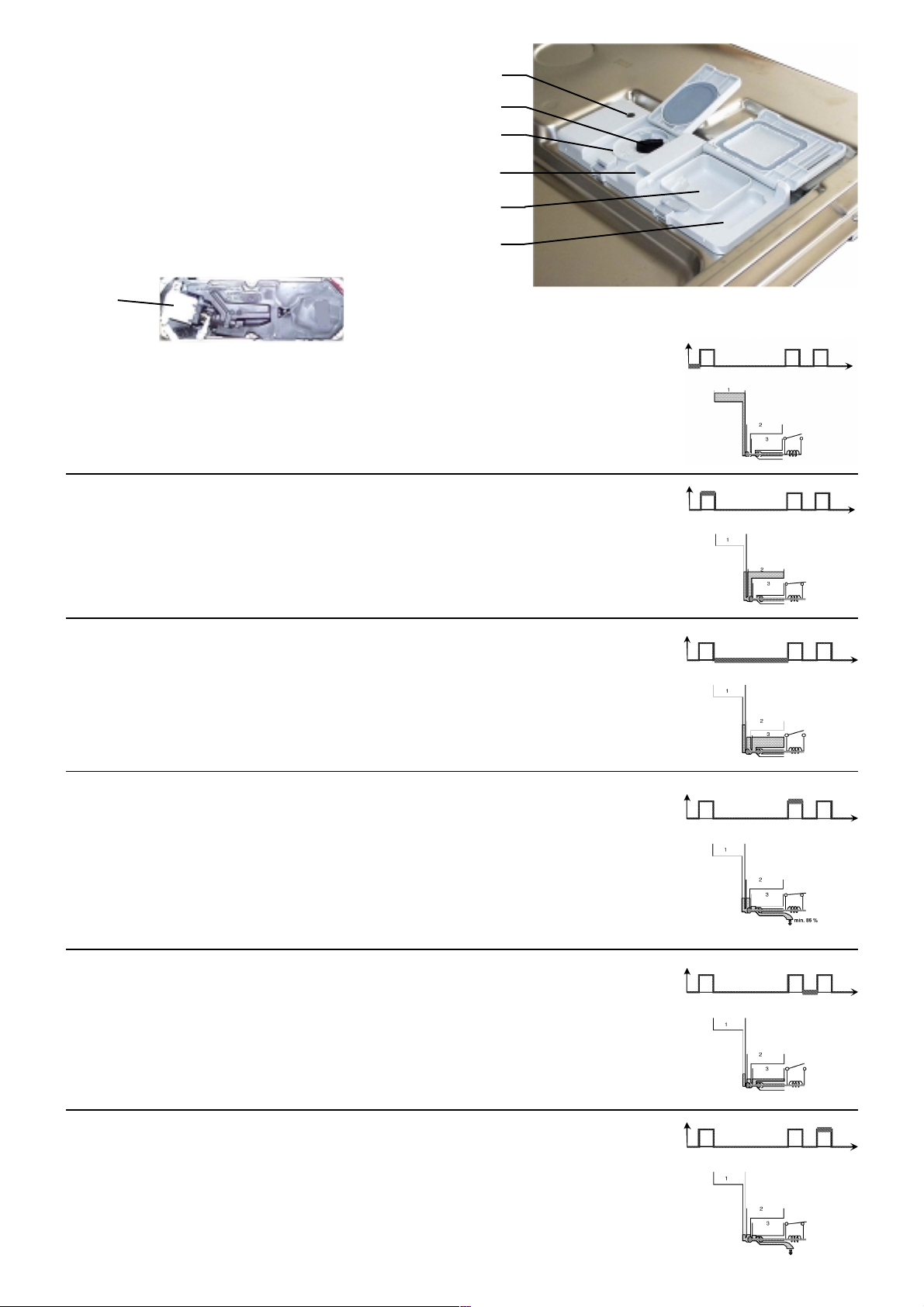
3.5 Detergent dispenser
display lack of rinse aid
Dosing of detergent
prewash 10 ml
wash 20 - 30 ml
Dosing of rinse aid
position 1 - 6 2 ml - 7 ml
Capacity
140 ml
coil
The detergent compartment 1 is filling corresponding to the set dosing
quantity when the door is open. Possibly existing rinse-aid in compartments
2 and 3 flows back into the storage tank of the rinse-aid. The detergent
trays are filled up. The door will be closed and the detergent for prewash
will be rinsed out through the slots in the detergent dispenser cover.
During the washing cycle the coil is switched on and the detergent
compartment cover releases the detergent. The rinse-aid flows from
compartment 1 into compartment 2.
dosing of rinse-aid
maximum filling level
outlet of rinse-aid
detergent tray
detergent tray for pre wash
Spule
EIN
AUS
EIN
AUS
Zeit
Zeit
After switching off the coil, the rinse-aid flows from compartment 2 into
compartment 3.
During the rinse cycle, the coil will be switched on when the rinse is warmed
and the rinse-aid runs from compartment 3 into the rinse tank. At the same
time, the remaining rinse-aid (15 %) runs from compartment 1 into
compartment 2.
With the coil switched off, the rinse-aid flows from compartment 2 into
compartment 3.
EIN
AUS
Zeit
EIN
AUS
Zeit
EIN
AUS
Zeit
EIN
During the rinse cycle, the coil is always switched on twice. When it is
AUS
Zeit
switched on the second time, the remaining rinse-aid flows into the rinse
tank.
05.2002 R.K. 599 514 DE
- 5 -
3.6 NTC-Temperature sensor with
integrated turbidity sensor
Turbidity sensor
NTC
Temp. Widerstand
10°C 9653 Ohm
25°C 4843 Ohm
60°C 1204 Ohm
90°C 445 Ohm
The turbidity sensor function is only activated in cycles AUTO
Function:
The input voltage with the turbidity sensor may be between 6 V
and 11.4 V. (The measurements are described in detail in the
chapter Measuring Points at the Electronic Control (in the base)).
For a clear water the output voltage must always be 4.3 V. If that
value differs due to soiling of the turbidity sensor after a longer
operational period, the Easytronic plus recontrols the input voltage
with the turbidity sensor automatically until the output voltage is
4.3 V. This happens during the final rinse cycle.
If the 4.3 V is not achieved within 8 seconds, the fault C5 is
stored in the fault memory. If the output voltage falls below 3 V in
the prewash cycle and below 3.8 V in the intermediate rinsing
cycle, turbid water will be detected. With the service test routine
the turbidity sensor will be calibrated to 3.5 V not with water but
with air.
That corresponds to 4.3 V with water.
NTC
output voltage prewash
turbit water clear water
output voltage intermediate
turbit water clear water
3,8V
4,3V3V
4,3V
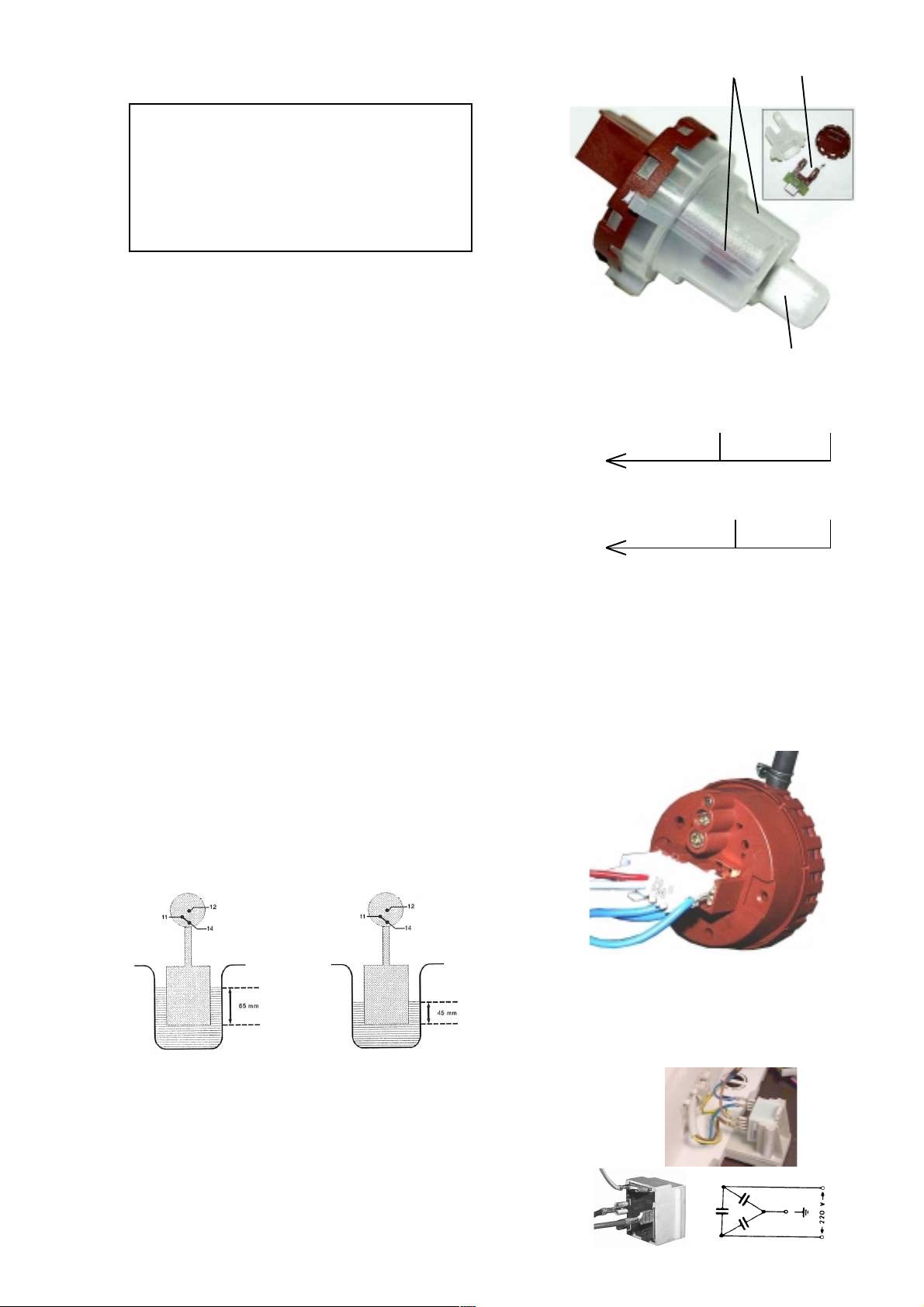
3.7 Pressure Switch
The pressure switch controls the water level.
Without water, contact 11 - 12 is closed.
fN Switch point with level 65 mm Ws
Reset point with level 45 mm Ws
The pressure switch is not adjustable.
3.8 Interference Filter
The interference filter is connected in the terminal board parallel to the mains feed.
05.2002 R.K. 599 514 DE
- 6 -
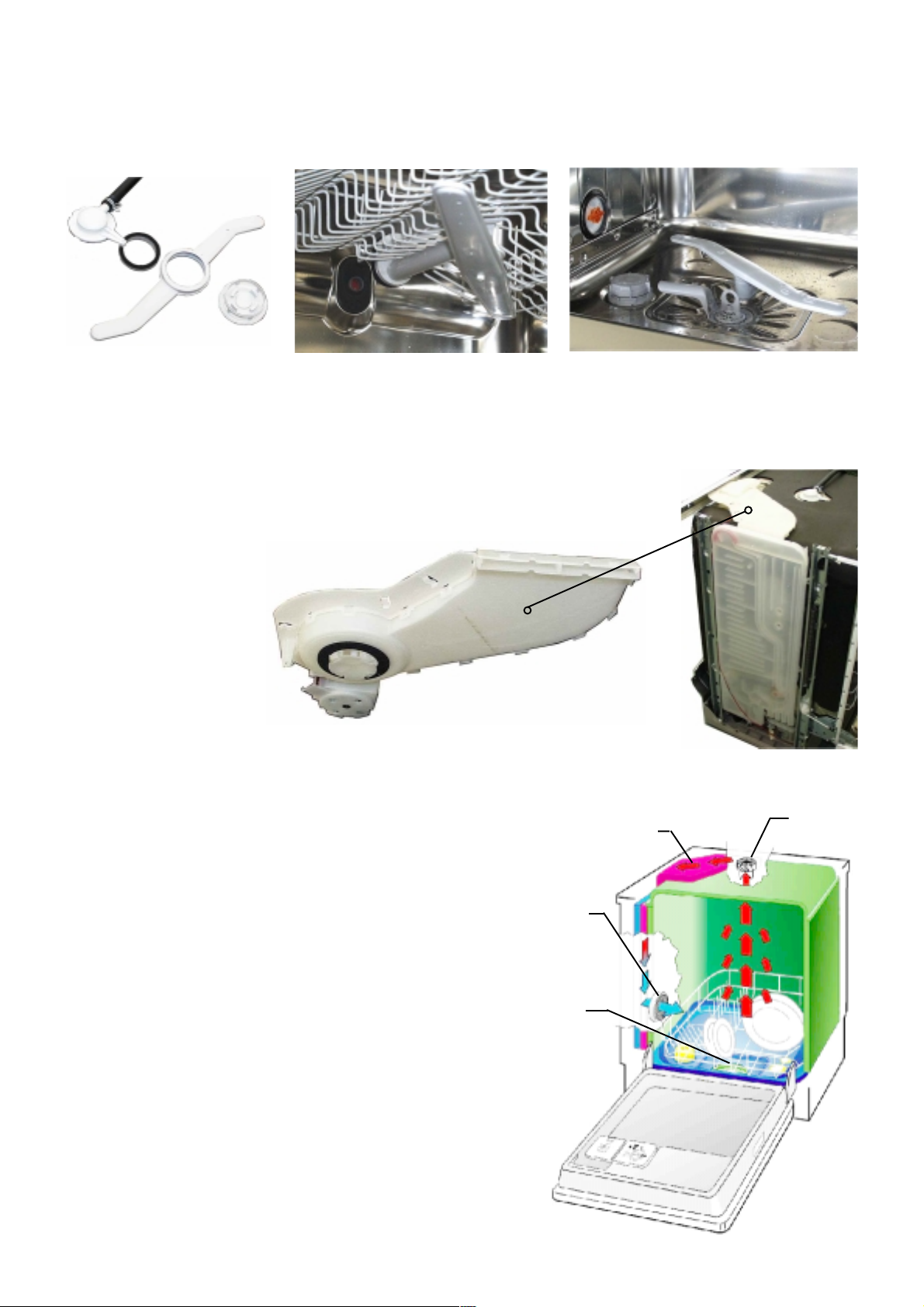
3.9 Spray arms
The new cutlery basket is placed at the upper diswasher basket. The celling sprayarm sprays the water
directly onto the cutlery basket and tguarantees an excellent washing result with the cutlery placed in
that basket.
Celling spray arm
upper spray arm lower spray arm
3.10 Drying fan
The new drying fan is located at the top on the rinse tank.
Function mode of the condensing drying
Rinse tank, fan and regenerating dosing with
condenser form a closed circuit. The humid air is
sucked from the top of the rinse tank and blown
through an air guide between rinse tank and
regenerating dosing. Thereby the air gets dry and
the condensate is guided to the drain tub.
The dry air gets through the rinse tank ventilation
into the rinse tank. During the drying phase, the
condenser is additionally cooled with 1 liter of
water.
rinse tank
ventilation
drain tub
air guide for
condenser
fan
05.2002 R.K. 599 514 DE
- 7 -
3.11 Regenerating dosing
with condenser
With every filling step, the condenser
cools down due to the cold incoming
water. Therefore another 1 liter of water
is required during the drying cycle.
1. softener unit
3.11.1 Water softening/regeneration
The water softening can be adjusted in 10 levels. The incoming
water flows until positon 5 to 85 % through the softener which
works according to the ion exchange principle. The ion exchanger
is filled with small epoxy resin balls. The resins exchange the
hardness constituents (calcium and magnesium), for sodium
ions.
When all the sodium ions are used up, it is necessary to
regenerate the softener. This is done by flushing a brine solution
through the softener.
Afterwards the softener is washed out with fresh water and is now
fully effective.
Depending on the water hardness, regeneration is only necessary
after several wash cycles.
The remaining 15 % of water flow through the rinse tank ventilation
directly into the appliance.
2. regeneration dosage
chamber
2
1
From setting of level 6, the whole water flows through the
softener. For this purpose you also have to set mechanically from
0 to 1 with the regenerating dosing.
With the setting of level 9, it is additionally regenerated after the
washing in a rinse cycle. With the settings 1 to 8, it is regenerated
after the final rinse depending on need. The softening system is
designed for a water hardness of up to 70 °dH.
05.2002 R.K. 599 514 DE
- 8 -
2
1
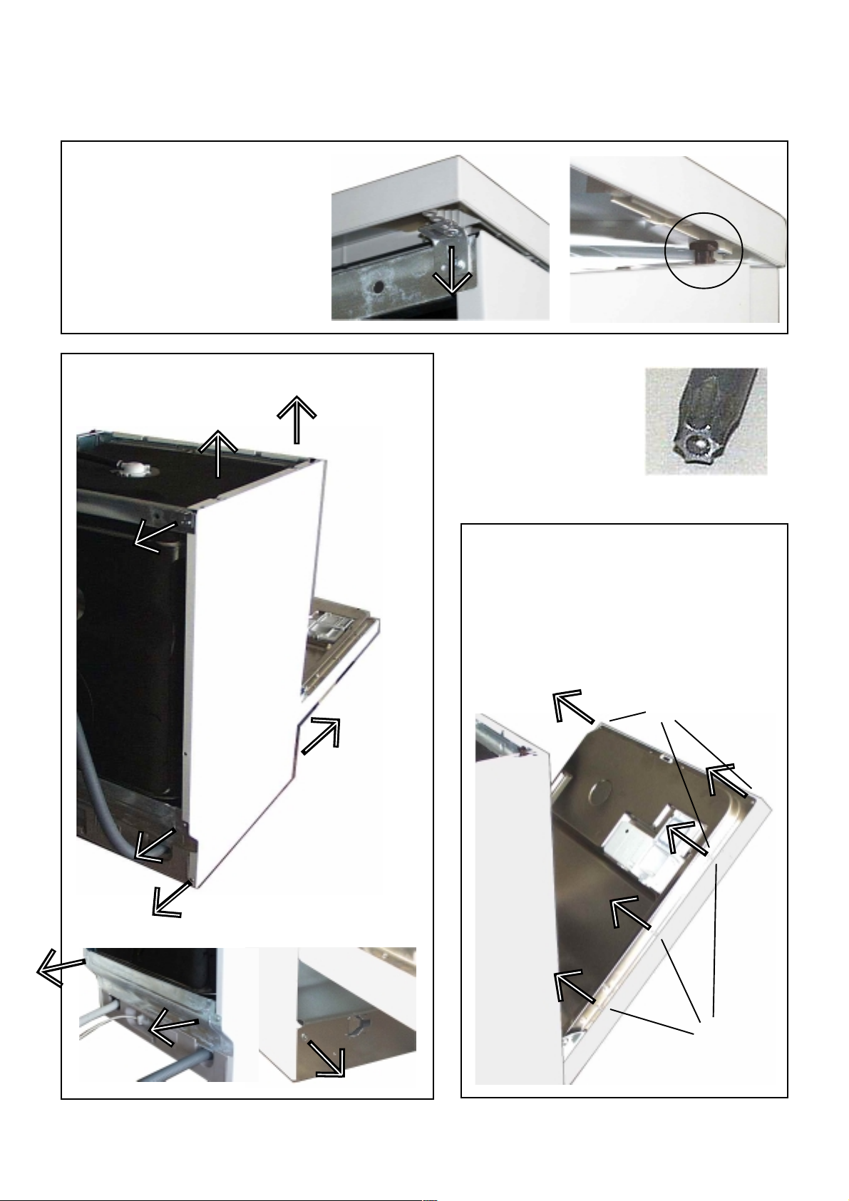
4. Service tips
4.1 Open the housing
Remove the screws (Abb.1) of the
upper plate on the left and right side.
Push the upper plate in front direction
to remove the plate (Abb.2).
To remove side panel remove fixing screws, pull
the panel away from the rear, and gently out of
the front trim. (pic.1).
1
1
You need
Torx epuipment
Remove the screws (1) to pull the
outer door away.
2
Removing the
cover plates of the
base area, remove
these screwst
(Abb1+2).
To remove the panel, remove the
fixing screws (2) .
2
1
2
3
05.2002 R.K. 599 514 DE
- 9 -

4.2 Position of Components
Detergent dispenser (1)
Spray arms (2)
Roof-mounted shower (3)
Salt container (4)
Filter (5)
3
5
4
2
Type plate (6)
On/Off-Switch (1)
Electronic (2)
Electronic
Panel (1)
Detergent dispenser (2)
1
6
1
2
1
2
Thermal sensor (3)
Drain pump (4)
Pressure switch (5)
3
05.2002 R.K. 599 514 DE
- 10 -
4
5
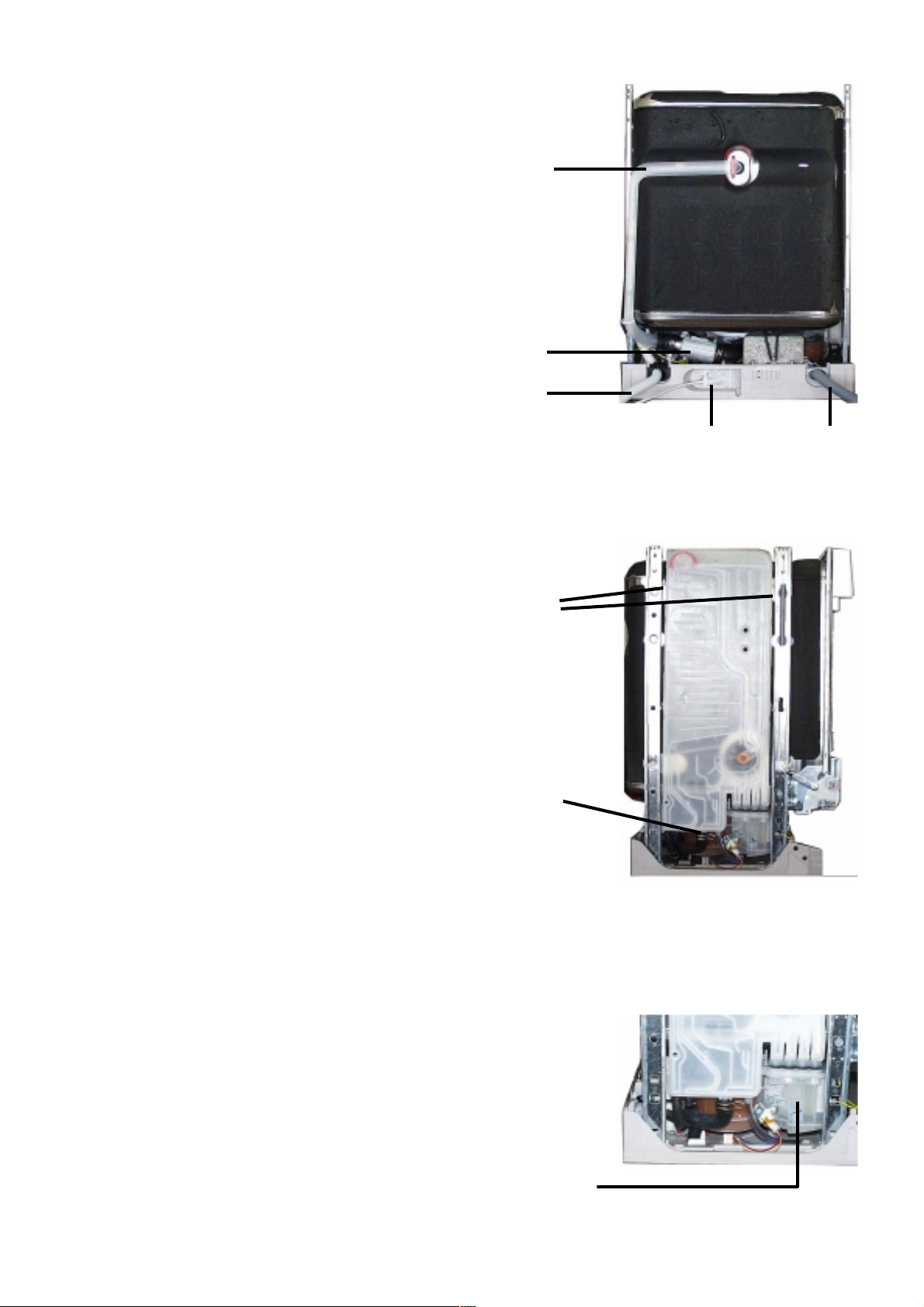
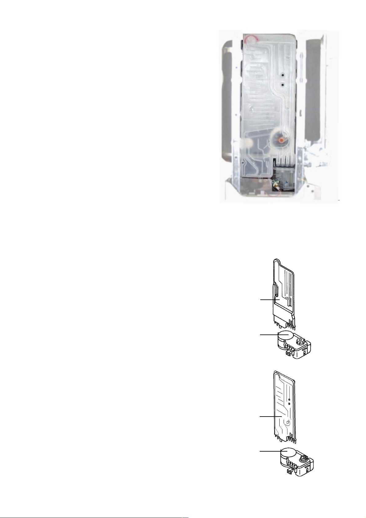
Back side view
- Flow heater (1)
- Terminal box (2)
- Inlet hose (3)
- Drain hose (4)
5
- Water inlet for above spray arm (5)
Removing the detergent dosage chamber:
- disengage locking tabs (1), disconnect hoses (2)
- holding the top of the chamber, pull upwards
disengaging it from the softener.
1
4
2
3
1
Removing the softener unit :
- remove the securing nut located under the salt cap.
- press softener (1) down and remove it through the front
from the base area
- CAUTION if accessible release reed switch.
2
1
05.2002 R.K. 599 514 DE
- 11 -
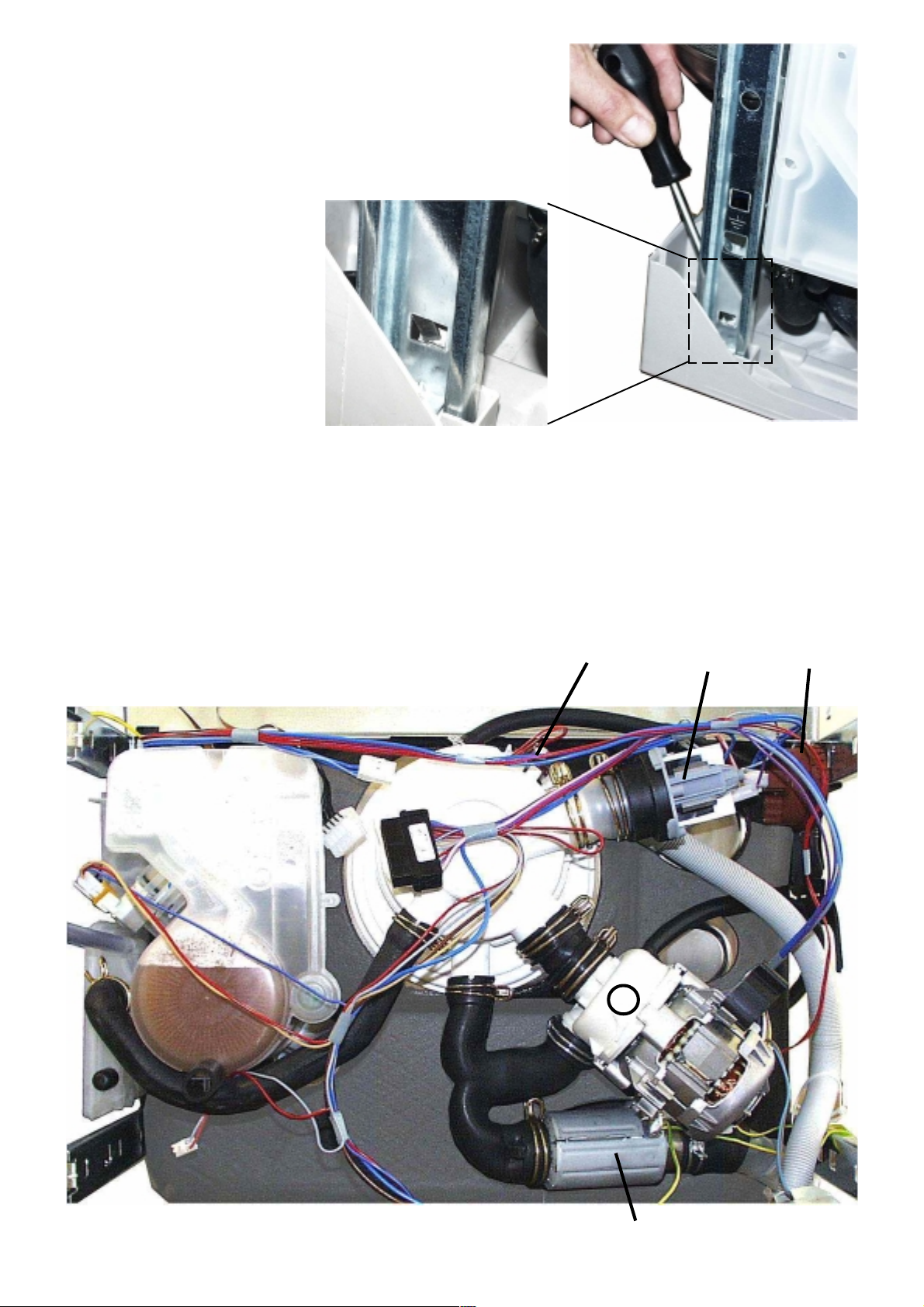
Removing the base :
- remove side panels, rear panel and plinth panel
- gently release base fixing clips with a screwdriver (figure)
- take off base carefully and release circulation pump,
electronic and heater relay
- disconnect the float switch
With base removed, following components are accessible:
- Drain pump (1)
- Circulation pump (2)
- Flow heater (3)
- Temperature sensor / Turbidity sensor (4)
- Pressure switch (5)
4
1
5
2
3
05.2002 R.K. 599 514 DE
- 12 -
 Loading...