

Electrolux Diva, Diva_EDW1100 Service Manual
SOI/TD PR 1/35 599 35 90-23
SERVICE MANUAL
DISHWASHERS
© ELECTROLUX HOME PRODUCTS ITALY S.p.A.
Spares Operations Italy
Corso Lino Zanussi, 30
Publication no.
I - 33080 PORCIA /PN (ITALY)
599 35 90-23
Fax +39 0434 394096
Edition: 2006-02
EN
Dishwasher with
EDW1100 electronic
control system
(Functionalities)
“DIVA”
Production:
ZM - Solaro (IT)

SOI/TD PR 2/35 599 35 90-23

SOI/TD PR 3/35 599 35 90-23
CONTENTS
1 Purpose of this manual.......................................................................................................................5
2 PRECAUTIONS..................................................................................................................................5
3 GENERAL CHARACTERISTICS........................................................................................................5
4 AESTHETIC CHARACTERISTICS: ...................................................................................................6
4.1 CONTROL PANEL ..............................................................................................................................7
4.1.1 Control panel.................................................................................................................................................7
4.1.2 ON / OFF button (S0)....................................................................................................................................7
4.1.3 Programme/Option buttons (S1÷S6).............................................................................................................7
4.1.4 Programme indicator LED.............................................................................................................................7
4.1.5 Indicator LEDs ..............................................................................................................................................8
4.1.6 Display..........................................................................................................................................................8
4.2 Options.................................................................................................................................................8
4.2.1 “ 3 in 1 Tablet” ...............................................................................................................................................8
4.2.2 Extra rinse (rinse +).......................................................................................................................................8
4.2.3 “1/2 load”.......................................................................................................................................................8
4.2.4 “Sanitize”.......................................................................................................................................................8
4.2.5 Delayed start.................................................................................................................................................9
4.3 Cancelling a programme....................................................................................................................10
4.3.1 Reset ..........................................................................................................................................................10
4.3.2 Interruption of a programme (pause) ..........................................................................................................10
4.4 Power failure......................................................................................................................................10
4.5 Sequence of operations.....................................................................................................................11
5 HYDRAULIC CIRCUIT .....................................................................................................................12
6 ELECTRICAL COMPONENTS AND THEIR FUNCTIONS.............................................................. 13
6.1 EDW1100 Electronic control system.................................................................................................13
6.1.1 Functions of the circuit board......................................................................................................................13
6.1.2 Memory in the control system.....................................................................................................................13
6.2 Specifications for actuators and sensors...........................................................................................14
6.2.1 Components................................................................................................................................................14
6.2.2 Sensors.......................................................................................................................................................14
6.3 Power supply and programme selection ...........................................................................................15
6.4 Fill circuit............................................................................................................................................16
6.4.1 Level and anti-overflow pressure switch.....................................................................................................16
6.4.2 Fill system...................................................................................................................................................16
6.4.3 Anti-flooding device.....................................................................................................................................16
6.4.4 Intervention of the anti-overflow system......................................................................................................16
6.5 Control of water fill phase..................................................................................................................17
6.5.1 Static fill ......................................................................................................................................................17
6.5.2 Dynamic fill..................................................................................................................................................17
6.5.3 Level stability control...................................................................................................................................17
6.6 Water fill time.....................................................................................................................................17
6.6.1 Static fill time...............................................................................................................................................17
6.6.2 Dynamic fill time..........................................................................................................................................17
6.6.3 Power supply interruption during water fill ..................................................................................................17
6.7 Level stability during washing............................................................................................................18
6.8 Washing system ................................................................................................................................18
6.8.1 Control of the washing pump ......................................................................................................................18
6.9 Heating...............................................................................................................................................19
6.10 Integrated detergent dispenser..........................................................................................................19
6.11 Disactivating the rinse-aid function....................................................................................................20
6.12 Drain ..................................................................................................................................................20
6.13 Regeneration system.........................................................................................................................21
6.14 Resin washing....................................................................................................................................21
6.15 Regeneration levels...........................................................................................................................22
6.15.1 Setting the regeneration level .....................................................................................................................22
6.15.2 “Blending” function......................................................................................................................................22
6.15.3 Table of regeneration values.......................................................................................................................23
7 Drying................................................................................................................................................23
7.1.1 “Turbo-dry” drying.......................................................................................................................................23
8 Automatic cycle (only on some models)...........................................................................................24
8.1 Turbidity sensor .................................................................................................................................24
8.1.1 Calculating the degree of soiling.................................................................................................................24
8.1.2 Determination of the load............................................................................................................................24
8.2 Automatic Programme.......................................................................................................................24
9 Alarms...............................................................................................................................................25

SOI/TD PR 4/35 599 35 90-23
9.1
Table of alarms..................................................................................................................................25
10 Diagnostics mode / Options..............................................................................................................27
10.1 Accessing diagnostics mode .............................................................................................................27
10.2 Reading the alarms and activating the individual components .........................................................27
10.3 Cancelling alarm codes from memory / Testing the LEDs................................................................28
10.4 Functional testing cycle .....................................................................................................................28
10.4.1 Selecting the cycle......................................................................................................................................28
10.4.2 Cycle phases ..............................................................................................................................................28
10.5 Options available to Service Engineers.............................................................................................29
10.5.1 Selecting the extra cold rinse option...........................................................................................................29
10.5.2 Disabling pulse washing .............................................................................................................................29
10.6 Exiting diagnostics mode...................................................................................................................29
11 ELECTRICAL FUNCTIONS..............................................................................................................30
11.1 Electrical circuit diagram....................................................................................................................30
11.2 Basic circuit diagram..........................................................................................................................31
11.2.1 Key to circuit diagram .................................................................................................................................31
12 Table of programmes........................................................................................................................32
12.1 60cm Dishwashers ............................................................................................................................32
12.2 45cm Dishwashers ............................................................................................................................33
14 Checking the efficiency of the components......................................................................................34
14.1 Measurement points on the board wiring connector..........................................................................34
15 QUICK GUIDE TO THE SPECIAL FUNCTIONS .............................................................................35
SOI/TD PR 5/35 599 35 90-23
1 Purpose of this manual
The purpose of this Service Manual is to provide Service Engineers, who already have the basic knowledge
necessary to repair household dishwashers, with technical information regarding dishwashers featuring the
EDW1100 electronic control system. These appliances are manufactured at Solaro (Italy).
The EDW1100 control system consists of a main circuit board and a control/display board. Both boards are
housed in a single plastic container. Some versions feature a display with only one digit.
This Manual describes:
• General characteristics
• Control panel and programmes
• Technical characteristics
• Guide to diagnostics
For more detailed information regarding the hydraulic circuits and the structural characteristics of the appliances,
refer to the Service Manual for presentation of the “DIVA” structure 599 35 55-25.
As regards the electric/electronic diagrams for a specific model please refer to spare parts list.
2 PRECAUTIONS
Electrical appliances must be serviced only by qualified Service Engineers.
Always remove the plug from the power socket before touching internal
components.
3 GENERAL CHARACTERISTICS
Power supply ⇒ 230 V / 50 Hz (limits 187÷254 V)
Total power absorption ⇒ 2300 W
Mains water supply ⇒ Pressure Min. / Max. 5 − 80 N/cm
2
Capacity ⇒ 9/12 place settings
Consumption (Energy Label):
Water ⇒ Lt. 14
Energy ⇒ KWh 0,8
Duration of Cycle ⇒ Min. 170
Controls B Vertical on upper edge of the door
- ON/OFF B Two-pole switch (separate from the electronic board)
- Selection of programmes/options B Button-actioned (min. 3, max. 6)
- Displaying B Display with one digit and/or LED
Washing system B Combined / Pulse
Control of water level B Pressure switch + Software
Water heating B Tube-enclosed heating element
Temperature control B NTC temperature sensor
Type of drying B Active / Turbo
Safety devices / Alarms B Total protection (hydraulic + Software)
SOI/TD PR 6/35 599 35 90-23
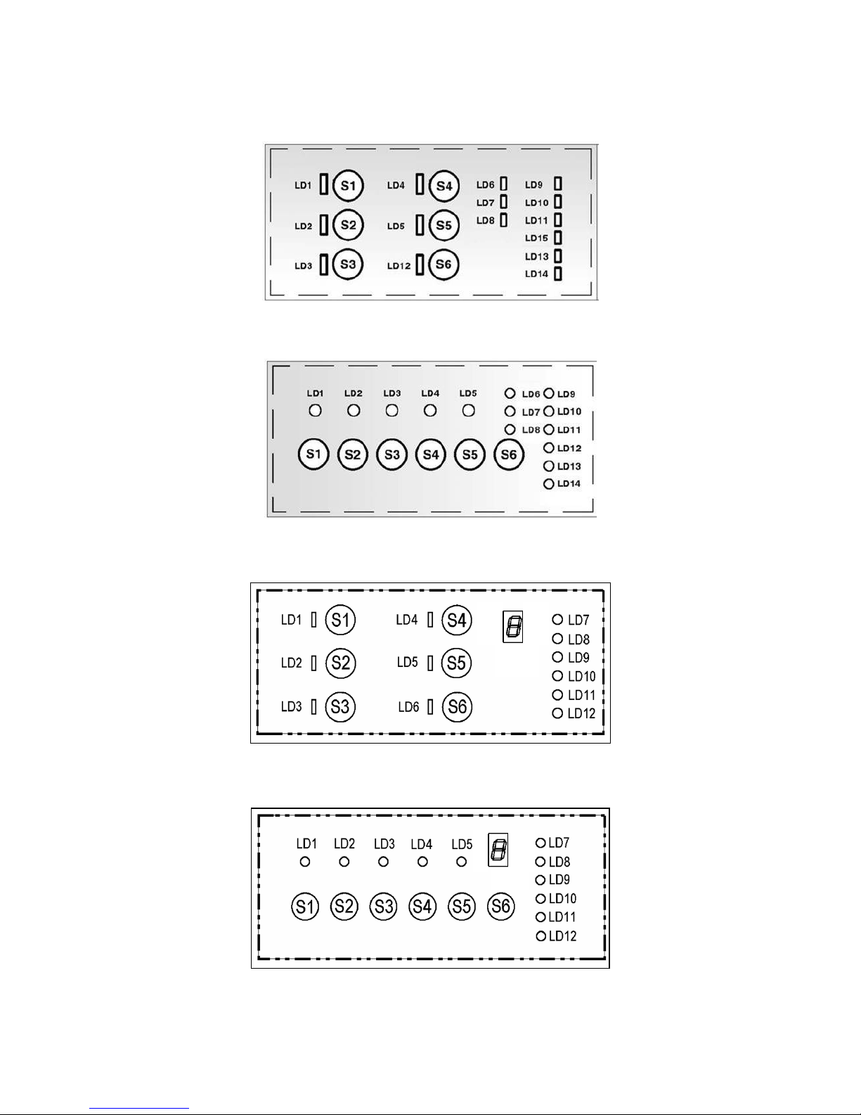
4 AESTHETIC CHARACTERISTICS:
Control panel with the maximum configuration: - VERTICAL Version
Control panel with the maximum configuration: - HORIZONTAL Version
Control panel with the maximum configuration with display: - VERTICAL Version
Control panel with the maximum configuration with display: - HORIZONTAL Version
SOI/TD PR 7/35 599 35 90-23
4.1 CONTROL PANEL
4.1.1 Control panel
The configuration of the control panel depends on the following:
Number of programme selection buttons (from a minimum of 3 to a maximum of 6)
Number of LEDs or presence of the one-digit display
[S0
] - ON/OFF button
[S1] … [S3] - PROGRAMME SELECTION buttons
[S4] … [S6] – PROGRAMME SELECTION and/or OPTIONS buttons
[LD1] … [LD3] - “PROGRAMMES” INDICATORS Leds
[LD4] [LD5] [LD12] - “PROGRAMMES and/or OPTIONS” INDICATORS Leds
[LD6] … [LD8] - “DELAYED START TIME” INDICATORS Leds
[LD9] … [LD11] - “CYCLE PHASES” INDICATORS Leds ([LD7] [LD9] in the version with 1 digit)
[LD13] [LD14] - “SALT / RINSE-AID” INDICATORS Leds
4.1.2 ON / OFF button (S0)
The ON/OFF button is featured on all models in the range, and is used to switch the applian ce on
and off. Switching off does not cancel the programme being executed.
4.1.3 Programme/Option buttons (S1÷S6)
These buttons are used to select the washing programme:
Press one of the buttons to select a washing programme
Within 3 seconds after selecting the programme, the user can enter the desired option(s) or select the
delayed-start function (if featured)
A specific LED is associated with each button
The dishwashers may have from a minimum of 3 to a maximum of 6 buttons
The following options may be featured:
- Delayed-start (3/6/9 hours in the versions without display and from 1 to 9 hours in the versions with
display)
- Half-load
- 3 in 1 tablet
- Extra rinse
- Sanitize
Buttons S1, S2, S3 are featured on all models; these are also used for certain Servicing functions
The functions of the various buttons depend exclusively on the software configuration of each
appliance. For more detailed information, refer to the table of programmes relative to the specific
model.
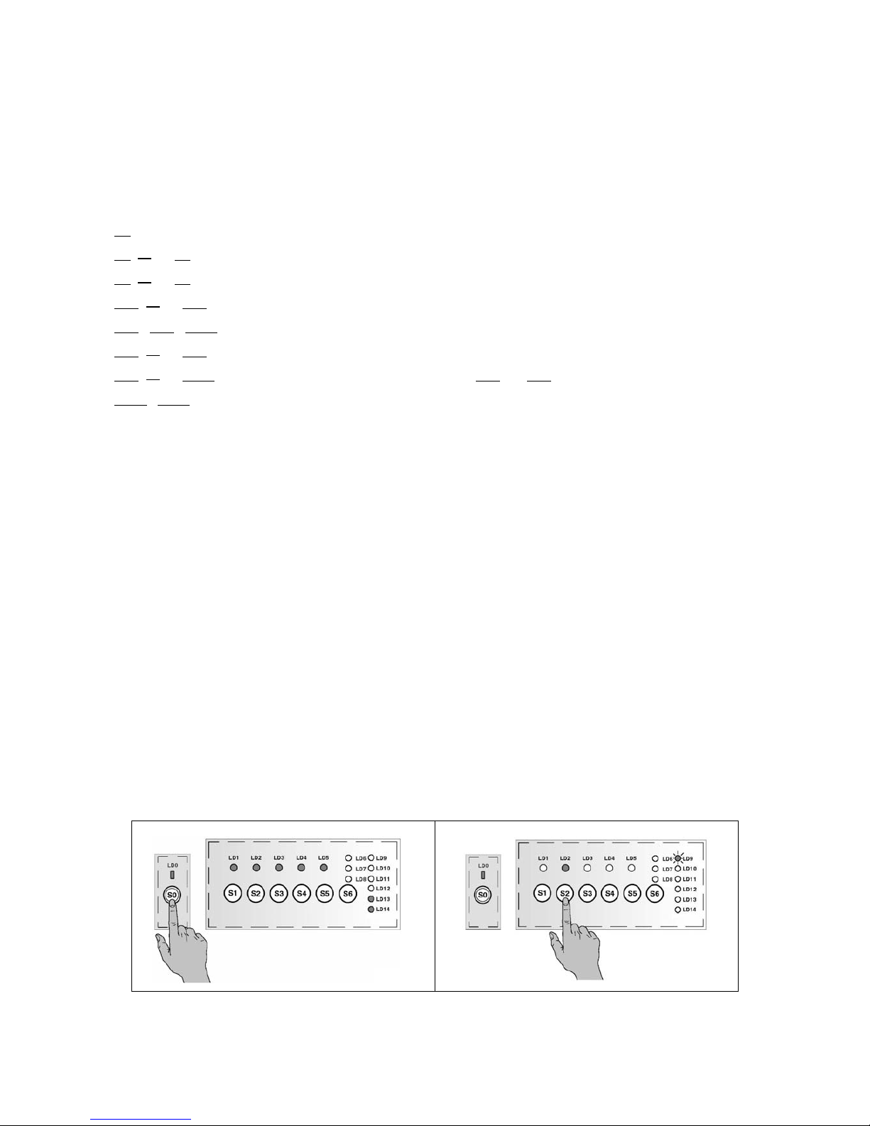
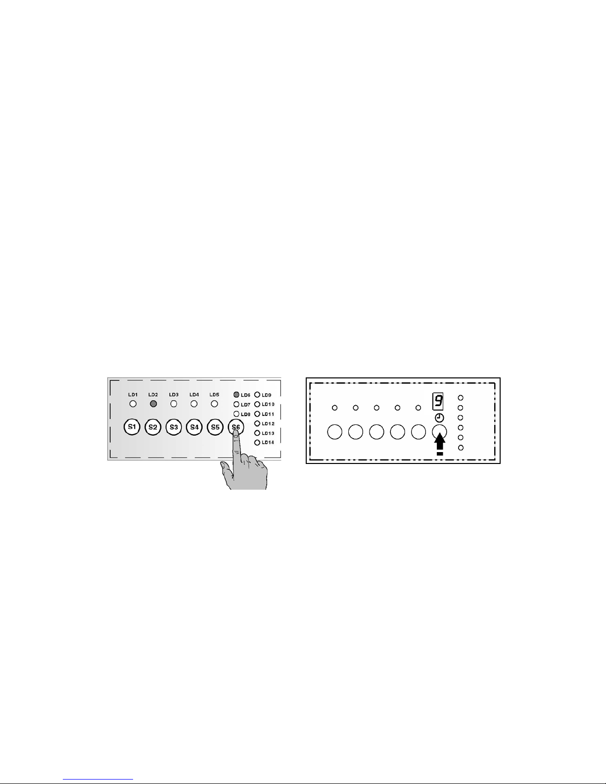
4.1.4 Programme indicator LED
1. When the appliance is switched on with S0 button (fig.1) the pre-selection phase is indicated
2. Pushing a programme button, the corresponding Led remains lit and, while the other switch off, the Led
of the current phase flashes (fig.2).
Fig.1 Fig.2

SOI/TD PR 8/35 599 35 90-23
4.1.5 Indicator LEDs
The indicator LEDs provide the user with the following information:
End of cycle: this LED is featured on all models.
Salt: indicates that the salt reservoir is empty. If the level of regeneration is set to “1” (no regeneration),
this LED remains unlit at all times.
Rinse-aid: indicates that the rinse-aid reservoir is empty.
Delay time: LEDs LD7, LD8, LD9 provide a sequential indication of the time to elapse before a delayed
start (3-6-9 hours)
4.1.6 Display
The one-digit display, if featured, shows only the delay time at the start: at every pressure of the
corresponding button the time increases by one hour till max. 9 hours.
The functions of the various LEDs depend on the software configuration of each appliance.
4.2 Options
4.2.1 “ 3 in 1 Tablet”
This option can be selected by pressing the corresponding button, and remains in memory until the same
button is pressed again. This option modifies the phases of the programme in order to optimize performance
when “3 in 1” detergent tablets are used:
variation of the duration of the programme and the temperatures required to dissolve the detergent
tablets.
reduction of water exchange (partial drain phases)
exclusion of introdu ction of rinse-aid
exclusion of regeneration / resin washing
4.2.2 Extra rinse (rinse +)
This option may be selected temporarily by pressing the button (if featured), or in “Service” mode. If this
option is set by the service engineer, it remains in memory until deactivated (see relative section).
This option adds o ne cold rinse (with pulse washing) with a duration of about 5 minutes.
4.2.3 “1/2 load”
The 1/2 load option optimizes the washing cycle when only a small load is placed in the appliance.
• 1/2 load button
When this button is pressed, certain parameters of the selected washing cycle are modified:
Exclusion of Pre-wash (if feature d)
Reduction of the wa shing temperature
Reduction of the duratio n of the programme
• Automatic ½ load
When this button is not featured on the control panel, certain programmes may feature automatic
detection of the half load. This system measures variations in the temperature during the initial heating
phase. The temperature and the duration of the wash are both reduced.
This option is not available in the following cycles: “Intensive”, “Short 30 minutes”, “Soak”, “Heating
plates” and “Glassware”.
4.2.4 “Sanitize”
This is a special option used to sanitize the dishes/cutlery. However, it is NOT compatible with the
“Glassware” programme.
During the final rinse, the temperature is maintained at 68°C for 10 minutes.
If used together with the SOAK option, the system performs a special sanitizing programme which lasts
approximately 46 minutes (1 hot rinse followed by 10 minutes at a constant temperature of 68°C)
SOI/TD PR 9/35 599 35 90-23
4.2.5 Delayed start
To select the delayed-start time:
1. Press button S0 to switch on the appliance.
2. Press a button to select the desired programme: the corresponding LED lights: for ex. S2, the relative
LED lights up.
3. Press the button repeatedly to select the delayed-start time:
• Version with LED:
o The Led LD8 lights to indicate that the function is active and that a 3 hour time has been
set (LD8 3; LD7 6; LD6 9 ore).
o Press the button once again to cancel the delayed-start time: the LEDs LD6÷LD8 switch
off.
o The delayed-start countdown begins when the door is closed:
When the countdown is at 9 hours, LED LD6 remains lit.
When the co untdown reaches 6 hours, LED LD7 remains lit.
When the co untdown reached 3 hours, LED LD8 remains lit.
When the countdown time has elapsed (0 hours), LEDs LD6 – LD8 switch off
and the cycle starts.
• Version with display:
o The display lights up and shows “1” to indicate that the function is active and that a 1
hour time has been set.
o Pressing the button once again the time increases every hour till max. 9 hours and then it
resets.
o The countdown starts when the door is closed: the display indicates the hours till “0” and
the programme starts.
Version with Led Version with Display
SOI/TD PR 10/35 599 35 90-23
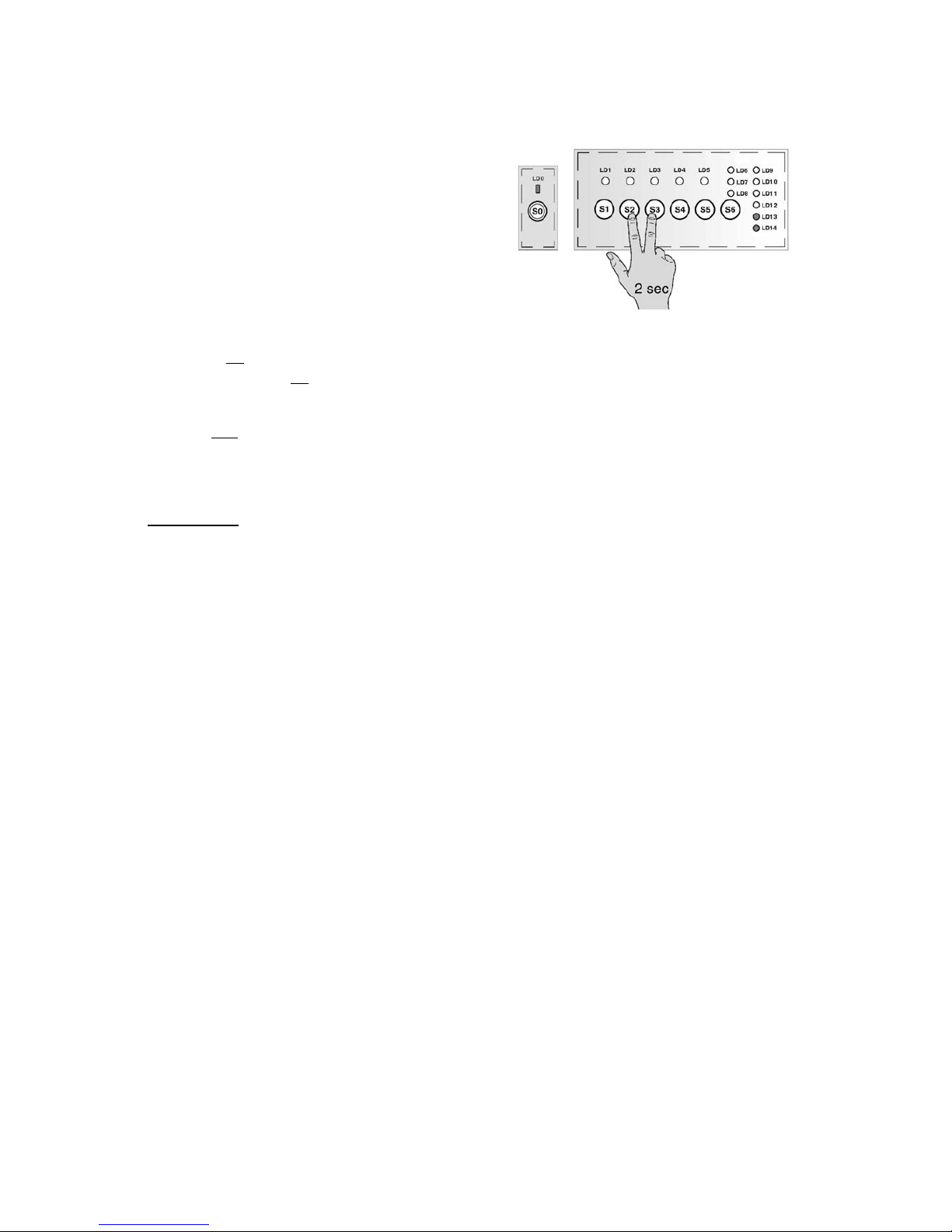
4.3 Cancelling a programme
4.3.1 Reset
To cancel a programme that has already started:
1. Open the door carefully and press buttons S2 - S3
together for approximately 2 seconds.
2. The salt and rinse-aid LEDs light: the programme is
cancelled and the appliance is in pre-selection mode.
3. Set the new cycle.
4.3.2 Interruption of a programme (pause)
If the button [S0] is pressed the power supply is cut and the appliance switches off.
By pushing the button [S0] again, the appliance starts and the cycle starts from the point at which it was
interrupted.
If the door is opened, the appliance is powered (the power loads are deactivated).
The LED [LD..] of the selected programme and the Option LED remain lit.
Closing the door again the cycle restarts with a little delay from the point at which it was interrupted.
Important! If the appliance is switched off or if the door is opened for more than 30 seconds during
the drying phase
, the cycle is considered to have been terminated after the regeneration phase; when
the appliance is switched on again, it returns to programme selection mode.
4.4 Power failure
The Power Failure function maintains the information relative to the cycle status even in the even of a power
outage; when the power supply is restored, the cycle resumes from the point at which it was interrupted.
If the power failure occurs during the drying phase, the cycle is conside red to have been terminated after the
regeneration phase.
The power failure condition has been defined as follows:
During a Power Fail all the loads are off in order to enable, through the energy stored in the power
capacitor of the control board, to save the data in the EEPROM and therefore when the power is
restored the cycle can restart from the point at which it was interrupted.
SOI/TD PR /35 599 35 90-23
11
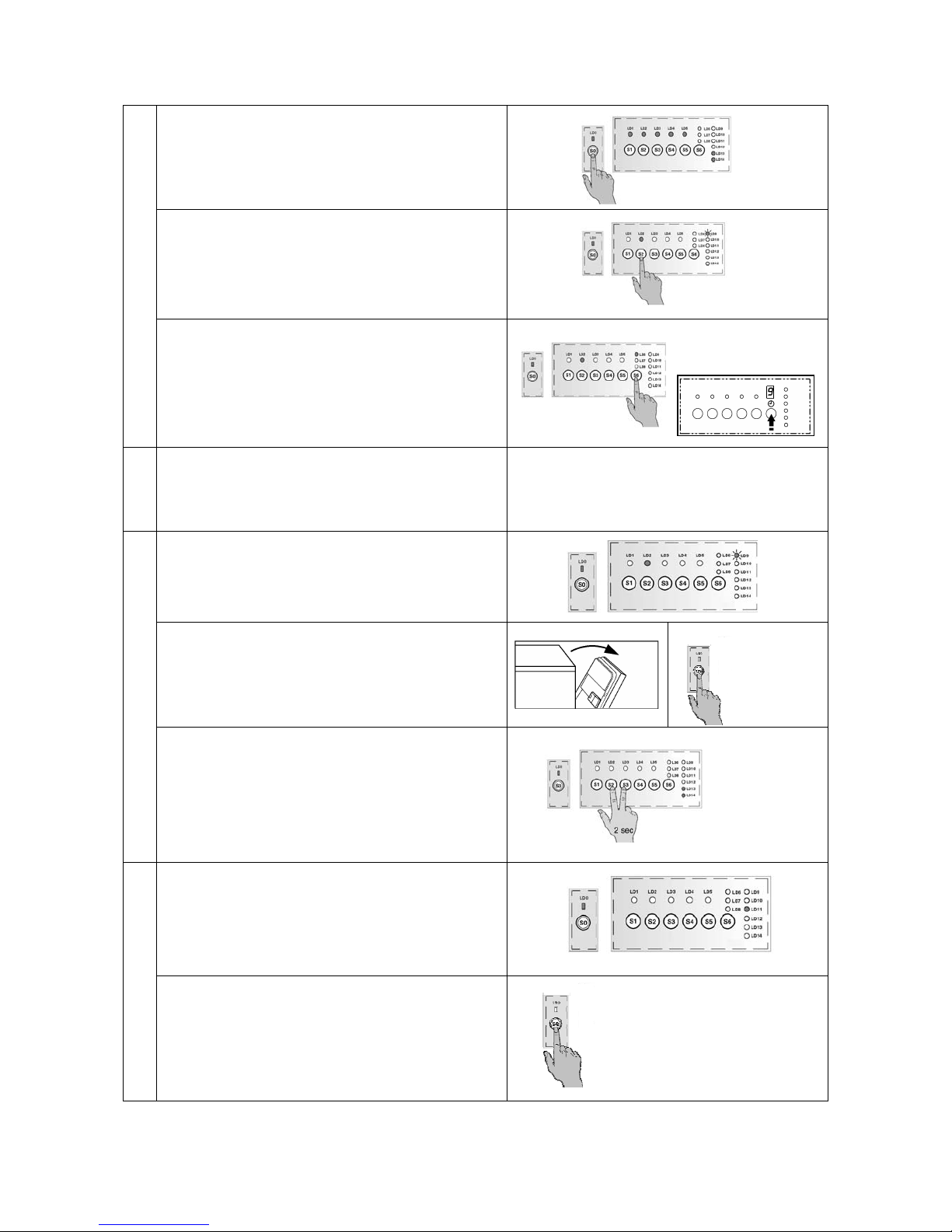
4.5 Sequence of operations
1. Press S0 to switch the appliance on.
All the LEDs corresponding to the programme/
option buttons light.
2. Press the button corresponding to the desired
programme.
The corresponding LED remains lit and the
relative cycle phase LED starts flashing.
SEELCTING THE CYCLE
3. If desired, select the delayed-start function or
other options (if featured).
START
4. The settings entered can be modified before
closing the door.
5. During the execution of the cycle, the relative
LED remains lit and the LED of the current
phase flashes.
6. To interrupt the current programme:
Open the door and, if necessary, press S0 to
switch off the appliance.
To re-start the appliance, press S0 again and
re-close the door.
EXECUTION OF THE CYCLE
7. To cancel the current programme:
Press S2 – S3 buttons at the same time for
about 2 seconds.
The salt and rinse-aid LE DS light.
Press the desired prog ramme button again.
8. At the end of the programme:
The END OF CYCLE LD11 LED lights; to
switch off the LED, open and re-close the door.
END
9. Press S0 to switch the appliance off.
 Loading...