

Electrolux DIVA 45-60-BIG Service Manual
SOI/TD 2005-2 PR /26 599 36 83-66
1
SERVICE MANUAL
DISHWASHERS
ELECTROLUX HOME PRODUCTS
ITALY S.p.A.
Spares Operations Italy
Corso Lino Zanussi, 30
Publication no.
I - 33080 PORCIA /PN (ITALY)
599 36 83-66
Fax +39 0434 394096
Edition: 2005-02
EN
Dishwasher with
electronic control
EDW 503
(Functionalities)
“DIVA” 45-60-BIG
“totally integrated”
911639… 911939…
911689… 911989…
Production:
ZM - Solaro (IT)

SOI/TD 2005-2 PR /26 599 36 83-66
2

SOI/TD 2005-2 PR /26 599 36 83-66
3
CONTENTS
1
Purpose of this manual ................................................................................................................................5
2 PRECAUTIONS ........................................................................................................................................... 5
3 GENERAL CHARACTERISTICS................................................................................................................. 5
4 CONTROL PANEL.......................................................................................................................................6
4.1 On/Off button (S0).............................................................................................................................. 6
4.2 Option selection button (S1) .............................................................................................................. 6
4.3 Programme selection button (S2) ...................................................................................................... 6
4.4 Options............................................................................................................................................... 7
4.4.1 “1/2 load”.....................................................................................................................................................7
4.4.2 Delayed start...............................................................................................................................................7
4.5 Cancelling a programme.................................................................................................................... 7
4.6 Interruption of a programme (pause) ................................................................................................. 7
4.7 Power failure ...................................................................................................................................... 7
5 SEQUENCE OF OPERATION..................................................................................................................... 8
6 HYDRAULIC CIRCUIT................................................................................................................................. 9
7 ELECTRICAL COMPONENTS AND FUNCTIONS ................................................................................... 10
7.1 EDW503 Electronic control system .................................................................................................10
7.1.1 Functions of the circuit board....................................................................................................................10
7.1.2 Memory in the control system ...................................................................................................................11
7.2 Specifications for actuators and sensors......................................................................................... 11
7.2.1 Components..............................................................................................................................................11
7.2.2 Sensors.....................................................................................................................................................11
7.3 Power supply and programme selection.......................................................................................... 12
7.4 Fill circuit .......................................................................................................................................... 12
7.4.1 Level and anti-overflow pressure switch ...................................................................................................12
7.4.2 Fill system.................................................................................................................................................12
7.4.3 Anti-flooding device...................................................................................................................................12
7.4.4 Intervention of the anti-overflow system....................................................................................................12
7.5 Control of water fill phase ................................................................................................................ 12
7.5.1 Static fill ....................................................................................................................................................12
7.5.2 Dynamic fill................................................................................................................................................12
7.5.3 Level stability control.................................................................................................................................12
7.6 Water fill time ................................................................................................................................... 13
7.6.1 Static fill time.............................................................................................................................................13
7.6.2 Dynamic fill time........................................................................................................................................13
7.6.3 Power supply interruption during water fill ................................................................................................13
7.7 Level stability during washing .......................................................................................................... 13
7.8 Washing system............................................................................................................................... 13
7.8.1 Control of the washing pump ....................................................................................................................13
7.9 Heating............................................................................................................................................. 13
7.10 Integrated detergent dispenser........................................................................................................14
7.11 Drain................................................................................................................................................. 14
7.11.1 Siphon” effect............................................................................................................................................14
7.12 Regeneration system....................................................................................................................... 15
7.13 Resin washing.................................................................................................................................. 15
7.14 Blending” function ............................................................................................................................ 15
8 DRYING ..................................................................................................................................................... 16
9 ALARMS..................................................................................................................................................... 17
9.1 Table of alarm codes .......................................................................................................................17
10 USER MODE ............................................................................................................................................. 19
10.1 Regeneration selection .................................................................................................................... 19
10.2 Buzzer.............................................................................................................................................. 19
11 SERVICE MODE........................................................................................................................................ 20
11.1 Reading the alarms and activating the individual components ....................................................... 20
11.2 Cancelling alarm codes from memory / test of LEDs ...................................................................... 20
11.3 Functional testing cycle.................................................................................................................... 21
11.3.1 Selecting the cycle ....................................................................................................................................21
11.3.2 Cycle phases ............................................................................................................................................21
11.4 Exiting Service and User modes...................................................................................................... 21
12 ELECTRICAL FUNCTIONS....................................................................................................................... 22
12.1 Electrical circuit diagram .................................................................................................................. 22
12.2 Basic circuit diagram........................................................................................................................23
12.2.1 Key to circuit diagram ...............................................................................................................................23
13 TABLE OF PROGRAMMES ......................................................................................................................24

SOI/TD 2005-2 PR /26 599 36 83-66
4
14
CHECKING THE EFFICIENCY OF THE COMPONENTS ........................................................................ 25
14.1 Measurement points on the board wiring connectors...................................................................... 25
15 QUICK GUIDE TO THE SPECIAL FUNCTIONS....................................................................................... 26
SOI/TD 2005-2 PR /26 599 36 83-66
5
1 Purpose of this manual
The purpose of this manual is to provide service personnel (who already have the basic knowledge
necessary for repairing dishwashers) with information on dishwashers equipped with the EDW503
electronic control system, which are produced in the Solaro (MI - Italy) factory.
The EDW503 control system consists of a main circuit board and a control/display board. Both
boards are housed in a single plastic container. It is used in some “DIVA” models.
This Manual describes:
• General characteristics
• Control panel and programmes
• Technical characteristics
• Guide to diagnostics
For more detailed information regarding the hydraulic circuits and the structural characteristics of the
appliances, refer to the Service Manual for presentation of the “DIVA” structure (publication number
599 35 55–25, 599 36 09-90).
2 PRECAUTIONS
Electrical appliances must be serviced only by qualified Service Engineers.
Always remove the plug from the power socket before touching internal
components.
3 GENERAL CHARACTERISTICS
Power supply ⇒ 230 V / 50 Hz (limits 187÷254 V)
Total power absorption ⇒ 2200 W (Resistance 2000W)
Mains water supply ⇒ Pressure Min. / Max. 5 ÷ 80 N/cm²
Capacity ⇒ 9/12 place settings (45/60 cm)
Consumption (prog. BIO):
Water ⇒ Lt. 14
Energy ⇒ KWh 0,8
Duration of cycle ⇒ 136’-143’ (45/60 cm)
Controls
- ON/OFF ⇒ On/Off function button
- Programme start ⇒ By button Start/Reset
- Programme selection ⇒ By knob (n°3÷5 programmes)
- Option selection ⇒ By 1 button
- Display ⇒ Leds
-
Washing system ⇒ Continuous (2600-2800 rpm)
Water fill level control ⇒ Pressure switch + Software
Water heating ⇒ Heating element enclosed in tube (2000 W)
Temperature control ⇒ NTC Temperature sensor
Drying systems ⇒ Active
Safety systems / Alarms ⇒ Total protection (hydraulic + Software)
SOI/TD 2005-2 PR /26 599 36 83-66
6
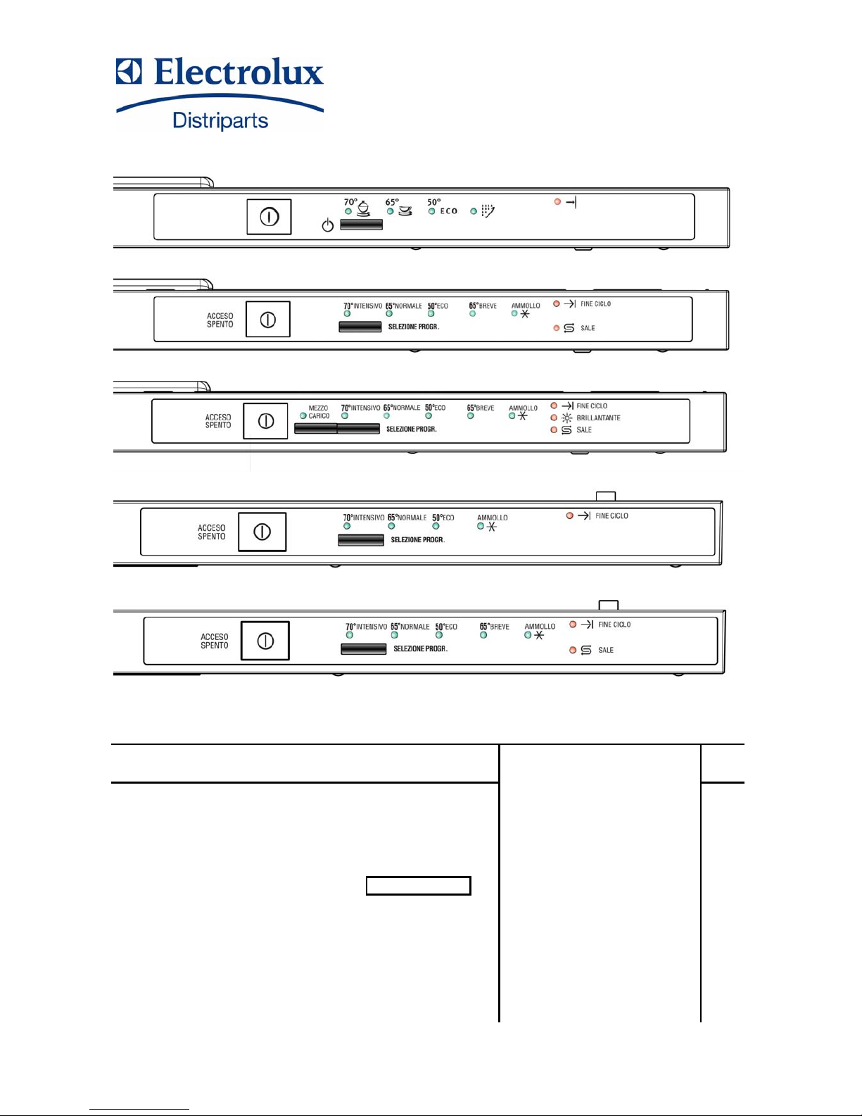
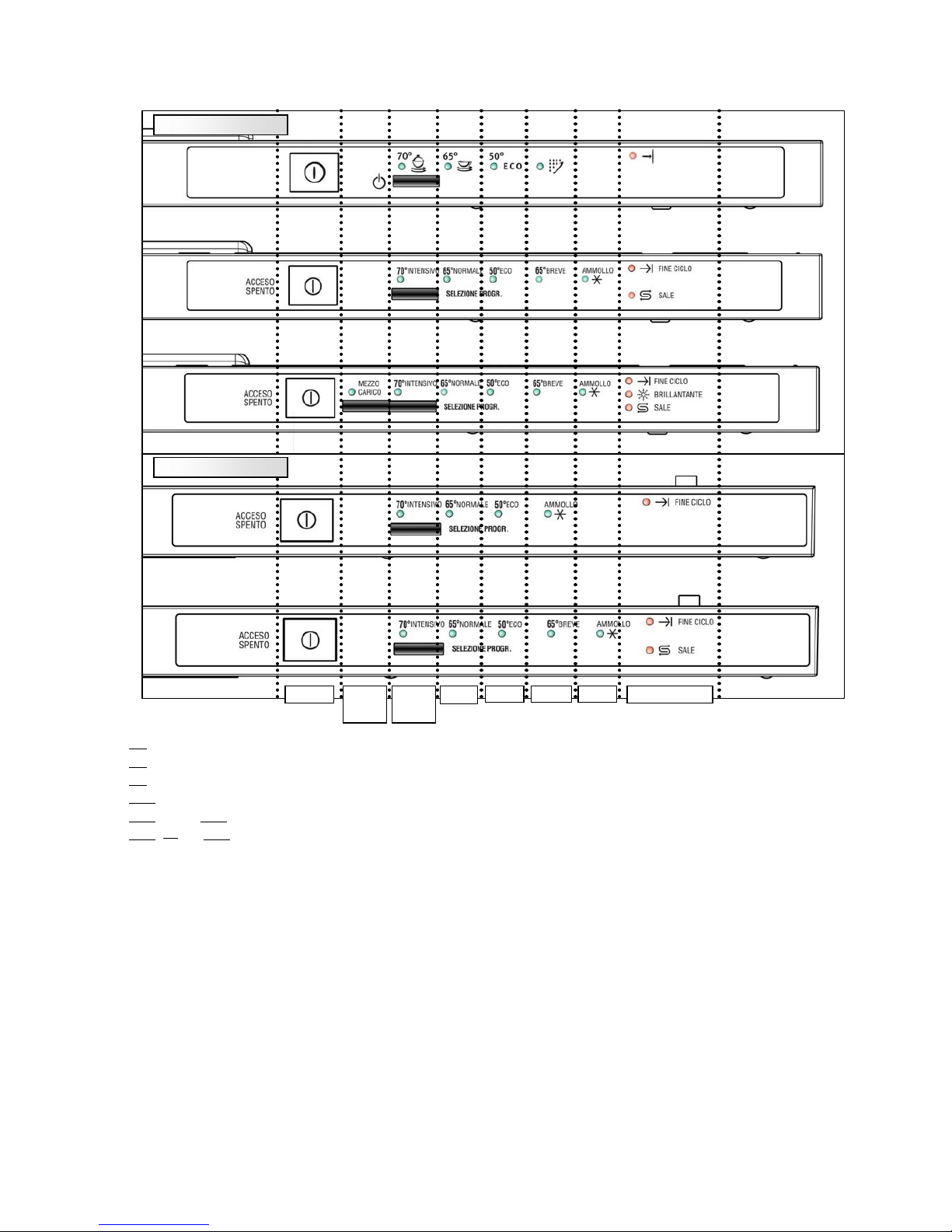
4 CONTROL PANEL
[S0
] - On/Off button (always featured)
[S1
] - Option selection button (only on some models)
[S2
] - Programme selection button (sequence)
[LD1
] - Option Led activated (only on some models)
[LD2
]- … - [LD6] – Washing programme LEDs
[LD7
] … [LD9] – Indicator LEDs: “End of cycle” (always present), “SALT” and “RINSE AID”
4.1 On/Off button (S0)
All models feature this button and it is used to switch on and off the appliance: the switching off does
not cause the cancellation of the current programme. When the appliance is switched on, only the End of
cycle LED is on and in case, if featured, the Salt and Rinse aid LEDs.
4.2 Option selection button (S1)
The system used for selecting the wash programmes depends on the configuration of the model. They
can be the “delayed start” or the “half load”: Switching off and on the dishwasher, the chosen settings are
cancelled.
4.3 Programme selection button (S2)
The functions of the various buttons and LEDs depend exclusively on the software configuration of
each appliance. With button S2 it is possible to scroll down sequentially all the available programmes: when
the button is pressed, the LED relative to the chosen programme lights.
When the button S2 is activated for the first time, the last programme performed is shown. This
button has also a Reset function.
S1
LD1
LD3
-
-
S2
LD2
45 cm
60 cm

SOI/TD 2005-2 PR /26 599 36 83-66
7
4.4 Options
4.4.1 “1/2 load”
The 1/2 load option optimizes the washing cycle when only a small load is placed in the appliance.
When this button is pressed, certain parameters of the selected washing cycle are modified:
Exclusion of Pre-wash (if featured)
Reduction of the washing temperature
Reduction of the duration of the programme
OR
4.4.2 Delayed start
This option enables the user to set a fixed start delay of the washing cycle.
to select the delayed-start time, with door open:
1. Switch the appliance on with S0 button.
2. Press the S1 button to select the delayed-start time: LED LD1 lights up to show that the selection has
been made.
The time reset when the relative button is pressed again: the LED LD1 switches off.
3. Select the programme pushing S2 button in sequence.
4. Close the door: the countdown starts.
5. When the countdown terminates, the selected cycle starts.
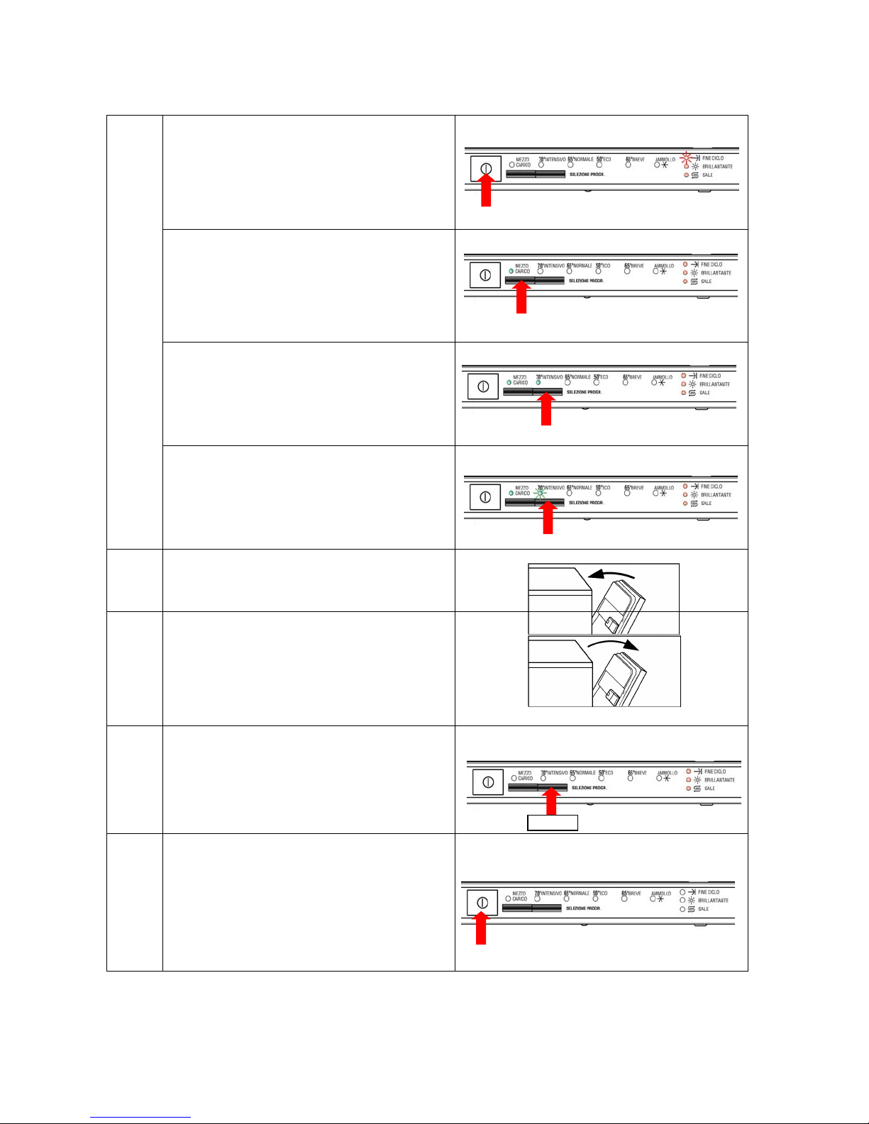
4.5 Cancelling a programme
To cancel a programme that has already started:
1. Press button S2 for at least 3 seconds.
2. The LED of the current programme flashes.
3. Salt/Rinse-aid LEDs light up (if featured): the programme is cancelled and the appliance returns to
preselection mode.
4. The End of cycle LED flashes.
5. Select the new programme.
4.6 Interruption of a programme (pause)
If the door is opened, the appliance remains on (the power loads are deactivated).
The Option LED remains on.
Closing the door the programme starts, after a brief delay, from the point at which it was interrupted.
Important! If the appliance is switched off or if the door is opened for more than 30 seconds during
the drying phase
, the cycle is considered to have been terminated after the regeneration phase;
when the appliance is switched on again, it returns to programme selection mode.
4.7 Power failure
The Power Failure function maintains the information relative to the cycle status even in the even of a
power outage; when the power supply is restored, the cycle resumes from the point at which it was
interrupted.
If the power failure occurs during the drying phase, the cycle is considered to have been terminated after the
regeneration phase.
The Power Failure has been defined in the following way:
When a Power Fail occurs, all loads switch off simultaneously to enable to save the data in EEPROM,
through the energy stored in the supply condenser of the control board, and when the power is restored, the
cycle restarts from the point at which it was interrupted.
SOI/TD 2005-2 PR /26 599 36 83-66
8
5 SEQUENCE OF OPERATION
1. Switch on the appliance with button S0
the “End of cycle” LED flashes every
2sec for 0.5sec.
eventually, if featured, the Salt/Rinse
aid LEDs light up.
2. Select the delayed start or the desired
option (if featured) pressing button S1.
the LED LD1 lights up.
3. Select the desired programme pressing
sequentially button S2.
the relative LED lights up.
SELECTING THE CYCLE
4. If LD2 flashes, there is an alarm condition
press button S2 to try and solve the
problem: if it is not ok LD2 will flash
again; consult the “Alarm” table for the
codification.
START
5. Close the door
The cycle starts automatically after
3sec or at the end of the countdown (if
the delayed start has been selected)
EXECUTION
OF CYCLE
6. To interrupt a programme in progress:
Open the door carefully.
To restart the cycle, close the door.
NB: Switching the appliance off and on, the
programme restarts from the point at which it
was interrupted.
CANCELLING
THE CYCLE
7. To cancel a programme in progress:
Open the door and press button S2 for
about 3 seconds.
The LEDs LD7 – 8 – 9 light up (if
featured).
The LD1 – 2 LEDs switch off and the
previous settings are cancelled.
END
8. At the end of the programme:
the buzzer emits a sound sequence.
The LED of the programme, the End of
cycle LED and the Salt/Rinse aid LEDs are
on, if featured.
9. Press button S0 to switch off the
appliance.
All LEDs switch off.
 Loading...