

Page 1

Summary
II. GENERAL INFORMATION ......................................................................................................................................................... 17
1. INSTRUCTIONS .......................................................................................................................................................................... 17
2 THE ENVIRONMENT .................................................................................................................................................................. 17
2.1. Packing .................................................................................................................................................................................. 17
2.2. Use .................................................................................................................................................................................... 17
2.3. Cleaning ................................................................................................................................................................................ 17
2.4. Disposal ................................................................................................................................................................................. 17
2.5. Radio interference ................................................................................................................................................................. 17
III. INSTALLATION ........................................................................................................................................................................... 18
1. GUIDELINES ................................................................................................................................................................................ 18
2. UNPACKING ................................................................................................................................................................................ 18
3. POSITIONING .............................................................................................................................................................................. 18
3.1. General Information .............................................................................................................................................................. 18
3.2. Securing to the floor .............................................................................................................................................................. 18
3.3. Combining appliances ........................................................................................................................................................... 18
3.4. Assembly and joining of counter top appliances on base, oven, bridge and cantilever frame ............................................ 18
3.5. Sealing gaps between appliances ........................................................................................................................................ 18
4. FUME EXHAUST ......................................................................................................................................................................... 18
4.1 Fume exhaust for type “B” appliances ................................................................................................................................... 18
4.1.1 Flue connection ............................................................................................................................................................ 18
4.1.2 Installation under an extraction hood .......................................................................................................................... 18
4.1.3 Installation with fume exhaust ducted to the outside or to a flue ............................................................................... 19
4.2 Fume exhaust for type “A1” appliances ............................................................................................................................... 19
5. CONNECTIONS ........................................................................................................................................................................... 19
5.1. Gas appliances ..................................................................................................................................................................... 19
5.1.1.Before connection ........................................................................................................................................................ 19
5.1.2.Connection ................................................................................................................................................................... 19
5.1.3.Checking the supply pressure ..................................................................................................................................... 19
5.1.4.Gas pressure regulator ...................................................................................................
5.1.5.Checking the primary air supply .................................................................................................................................. 19
5.1.6.Conversion to a different type of gas........................................................................................................................... 20
5.1.6.1 Replacing main burner nozzle ........................................................................................................................ 20
5.1.6.2 Replacing pilot burner nozzle ......................................................................................................................... 20
5.2. Electric appliances ................................................................................................................................................................ 20
5.2.1 Electrical connection .................................................................................................................................................... 20
5.2.2.Power supply cable ...................................................................................................................................................... 20
5.2.3.Circuit breaker .............................................................................................................................................................. 20
5.3. Earth and equipotential node connection ............................................................................................................................. 20
6. WATER SUPPLY CONNECTION ................................................................................................................................................ 20
7. DISCHARGE ................................................................................................................................................................................ 20
............................................. 19
IV USER INSTRUCTIONS ................................................................................................................................................................. 21
1. PASTA COOKER USE ................................................................................................................................................................. 21
1.1. Water filling............................................................................................................................................................................ 21
1.2. Gas models ........................................................................................................................................................................... 21
1.3. Electric models ..................................................................................................................................................................... 22
1.4. Cooking (valid for gas and electric models) ........................................................................................................................ 22
1.5. Water discharge .................................................................................................................................................................... 22
1.6. Models with instantaneous heater ........................................................................................................................................ 22
V. CLEANING 25
1. EXTERNAL PARTS ...................................................................................................................................................................... 23
2. OTHER SURFACES .................................................................................................................................................................... 23
3. SCALE .................................................................................................................................................................................... 23
4. IDLE PERIODS ............................................................................................................................................................................ 23
5. INTERNAL PARTS ....................................................................................................................................................................... 23
VI. MAINTENANCE ............................................................................................................................................................................ 24
1. MAINTENANCE ........................................................................................................................................................................... 24
1.1 Brief troubleshooting guide ............................................................................................................................................. 24
2. LIST OF COMPONENTS ...........................................................................................................
.................................................. 24
15
Page 2
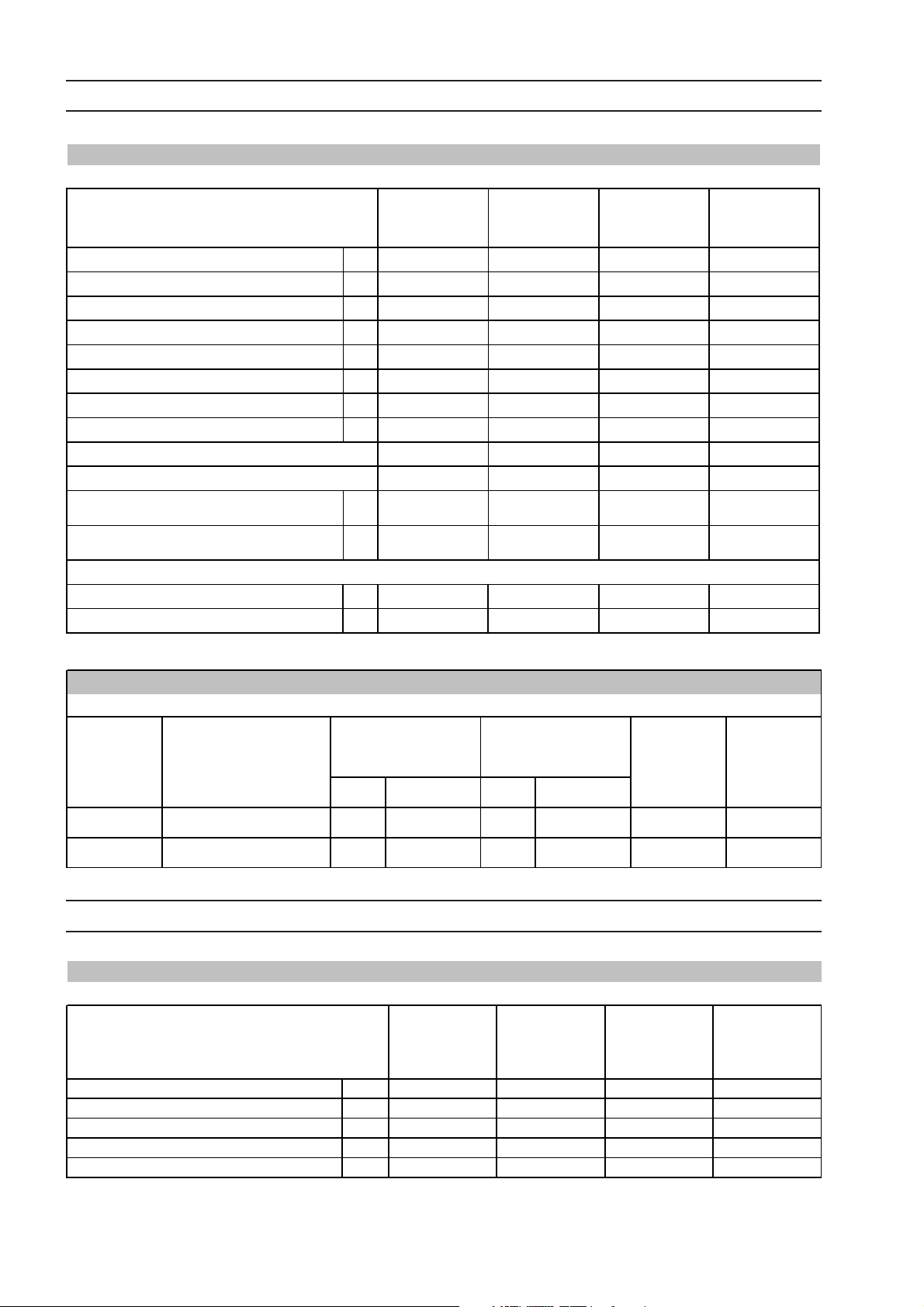
IB. TECHNICAL DATA AND GAS NOZZLE TABLES
TABLE A - Gas appl iance technica l data and supply pressures
MODELS +CP/G1 +CP/G1R +CP/G2 +CP/G2R
TECHNICAL DATA 1/2M
Power supply voltage V 230 400 230 400
Electrical power absorbed kW 0,1 3 0,2 6
Phases No. 1+N 3+N 1+N 3+N
Frequency Hz 50/60 50/60 50/60 50/60
Power supply cab le section mm
ISO 7/1 gas connection Ø 1/2” 1/2” 1/2” 1/2”
Burners No. 1 1 2 2
N ominal he at outp u t kW 14 14 28 28
Category
Type of construction
G20 natural gas supply pressure mbar 20 20 20 20
G30/G31 LPG supply pressure mbar 28-30/37 28-30/37 28-30/37 28-30/37
2
1,5 1,5 1,5 1,5
II 2H3+ II 2H3+ II 2H3+ II 2H3+
A1 A1 A1/B11/B21 A1/B11/B21
1/2M
Rapid System
1M
1M
Rapid System
Total gas consumption (calculated w ith lower heating power(Hi) at 15°C and 1013mbar):
- G30 LPG (H i = 45.65 MJ/kg) kg/h 1.1 1.1 2.2 2.2
- G20 natural gas (Hi = 34.02 MJ/m 3) m3/h 1.48 1.48 2.96 2.96
TABLE B – Burner nozzle, pil ot a nd slee ve opening
GAS type
G20 20 2.85 285 - - 31 25
G30/G31 28-30/37 1.9 190 - - 30 24
Pressure (mbar)
MAX nozzle MIN nozz le
mm Stamping mm Stamping
AERATOR
opening
(mm)
Pilot (No.)
IB. ELECTRIC APPLIANCE TECHNICAL DATA
TABLE C - Ele ctric appli ance te chnica l data
MODELS
TECHNICAL DATA
Power supply voltage V 400 400 400 400
Phases Nr. 3+ N 3+N 3+N 3+N
Frequency Hz 50/60 50/60 50/60 50/60
Max. total power kW 10 13 20 26
Power supply cable section mm
2
+CP/E1
1/2M
2.5 2.5 6 6
+CP/E1R
1/2M
Rapid System
+CP /E 2
1M
+CP /E 2R
1M
Rapid System
16
Page 3

II. GENERAL INFORMATION
2. THE ENVIRONMENT
1. INSTRUCTIONS
• Read this manual carefully before using the appliance.
• After installation keep the manual for future consultation.
• This manual contains instructions for various appliances.
See the appliance dataplate positioned under the control
panel in order to identify the appliance product code.
• FIRE HAZARD - Keep the area around the appliance
clear and free from combustible materials.
Do not keep flammable materials in the vicinity of the
appliance.
• Install the appliance in a well-ventilated place to avoid
the creation of dangerous mixtures of unburnt gases
in the room.
• Air recirculation must take in account the air
necessary for combustion, 2 m³/h/kW gas power, and
also the “well-being” of those working in the kitchen.
Inadequate ventilation causes asphyxia. Do not
obstruct the ventilation system of the place where
the appliance is installed.
Do not obstruct the vents or ducts of this or other
appliances.
• Affix emergency telephone numbers in a visible
position.
• Installation, maintenance and conversion to other types
of gas must only be carried out by qualified personnel
authorized by the manufacturer. For assistance, contact
an authorized service centre. Demand original spare
parts.
• This appliance is designed for the cooking of foodstuffs.
It is intended for industrial use. Any other use is
considered improper.
• Personnel using the appliance must be trained.
Do not leave the appliance unattended when operating.
• Turn off the appliance in case of fault or poor operation.
• Do not use (even if diluted) products containing chlorine
(sodium hypochlorite, hydrochloric or muriatic acid, etc.)
to clean the appliance or the floor under the appliance.
Do not use metal tools (wire brushes or Scotch Brite type
abrasive scouring pads) to clean steel parts .
• Do not allow oil or fat to come into contact with plastic
parts.
• Do not allow dirt, grease, food or other residuals to form
deposits on the appliance.
• Do not wash the appliance with direct jets of water.
Failure to observe the above could compromise the
safety of the appliance.
Failure to respect the above invalidates the warranty.
2.1. PACKING
Packing materials are environment friendly and can be
stored without risk, or burned in a special waste incineration
plant. Recyclable plastic components are marked with
PE Polyethylene:
outer wrapping, instruction booklet bag, gas nozzle bag.
pp Polypropylene:
roof packing panels, straps.
PS Polystyrene foam:
corner protectors.
2.2. USE
Our appliances offer high performance and efficiency. To
reduce consumption of electricity, water or gas, do not use
the appliance empty or in conditions that compromise optimal
efficiency (e.g. with the door or lid open, etc.); the appliance
is used in a well-ventilated place to avoid the creation of
dangerous mixtures of unburnt gases in the room.
When possible, pre-heat only before use.
2.3. CLEANING
In order to reduce the emission of pollutants into the
environment, clean the appliance (externally and when
necessary internally) with products which are more than 90%
biodegradable (for further information, see chap. V
“CLEANING”).
2.4. DISPOSAL
Do not disperse in the environment Our appliances are
manufactured using more than 90% (in weight) recyclable
metals (stainless steel, iron, aluminium, galvanized sheet,
copper, etc.
Make the appliance unusable by removing the power supply
cable and any door locking mechanisms in order to avoid
the risk of someone becoming closed inside.
2.5. RADIO INTERFERENCE
This appliance conforms to Directive EEC 89/336 relevant
to the suppression of radio interference.
:
17
Page 4

III. INSTALLATION
1. GUIDELINES
• (Fig. C) Turn one of the two plates inside the appliances 180º.
• (Fig. 1E) From inside the control panel of the same
appliance, join them at the front side, screwing one TE
M5x40 screw (supplied) on the opposite insert.
• Installation must be carried out by professionally qualified
personnel in compliance with current safety regulations.
2. UNPACKING
Remove the packing.
Carefully remove the protective film from metal surfaces.
Remove any traces of glue using a suitable solvent.
IMPORTANT! Immediately check for any damage caused
during transport.
• Inspect the packs before and after unloading.
• The forwarder is responsible for the safety of the goods
during transport and delivery.
• Make a complaint to the forwarder in the event of
apparent or hidden damage. Specify any damage or
shortages on the dispatch note.
• The driver must sign the dispatch note: the forwarder
can reject the claim if the dispatch note is not signed
(the forwarder can provide the necessary form).
• For hidden damage or shortages becoming apparent
only after unpacking, within and not later 15 days of
delivery request the forwarder for inspection of the
goods.
• Keep all the documentation contained in the packing.
3. POSITIONING
3.1. GENERAL INFORMATION
• The installation diagrams specify the overall dimensions
of the appliance and the positions of connections (water
inlet- gas inlet- power cable input).
• Appliances can be installed separately or in combination
with other appliances in the same range (see par. 3.3).
• The appliances are not suitable for built-in installation.
• Leave at least 10 cm between the appliance and side or
rear walls.
• Maintain an adequate distance between the appliance
and any combustible walls.
• Leave an adequate space between the appliance and
any side walls in order to allow subsequent servicing or
maintenance operations.
• Suitably insulate any surfaces that are less than the
specified distances from the appliance.
3.2. SECURING TO THE FLOOR
To avoid accidental tipping of monobloc half-module
appliances installed separately, fix them to the floor. The
relative accessory comes with instructions.
3.4 ASSEMBLY AND JOINING OF COUNTER
TOP APPLIANCES ON BASE, OVEN, BRIDGE
AND CANTILEVER FRAME
Follow the instructions supplied with the optional product
selected.
3.5 SEALING GAPS BETWEEN APPLIANCES
Follow the instructions supplied with the optional sealing
paste pack.
4. FUME EXHAUST
4.1 FUMES EXHAUST FOR TYPE “B”
APPLIANCES
Fit type “B” appliances with a fume exhaust system
complying with current regulations.
4.1.1 FLUE CONNECTION
• Remove the grid from the fume exhaust.
• Install the connection flue, following the instructions
supplied with the accessory (optional).
4.1.2 INSTALLATION UNDER AN EXTRACTION HOOD
• Place the appliance under
the extraction hood (fig.
opposite).
• Raise the fume exhaust duct
without altering the section.
• Do not install dampers.
• The correct height of the
exhaust duct and the
relative distance from the
extraction hood must comply
with current standards.
• The end of the exhaust pipe
must be at least 1.8 m from
the top surface of the
appliance.
4.1.3 INSTALLATION WITH FUME EXHAUST
DUCTED TO THE OUTSIDE OR TO A FLUE
• In the absence of an extraction hood, fit the fume
exhauster (optional).
• Fit the damper on the connection flue exhaust (optional).
• Fit the upward section of the damper into the connection
flue sleeve.
• Proceed to the outside or to a flue with a duct of adequate
size, resistant to 300°C.
3.3. COMBINING APPLIANCES
• (Fig. 1A) Undo the 4 fixing screws and remove the control
panels from appliances.
• (Fig. 1B) Remove the fixing screw nearest the control
panel, from each side to be joined.
• (Fig. 1D) Bring the appliances together and level them
by turning the feet until the tops of the appliances match.
• (Fig. 1F) From the rear of the appliances, insert the coupling
plate supplied into the side housings on the backs. Secure the
plate using two M5 flathead screws provided.
18
Note: the system must guarantee that: a) the fume exhaust
is not blocked; b) the length of the exhaust pipe does not
exceed 3 m. Use the adapter for connecting fume ducts of
different diameters.
IMPORTANT! Delete the “Type” of installation not carried
out from the appliance dataplate, so that only the “Type” of
installation executed remains.
Page 5

4.2 FUME EXHAUST FOR TYPE “A1”
1-4
1-2
1-3
APPLIANCES
Position type “A1” appliances under an extraction hood to
ensure removal of fumes and steam produced by cooking.
5. CONNECTIONS
See the appliance dataplate for the appliance product code.
See the installation diagrams for the position of connections
on the appliance.
- GAS
- ELECTRICITY
- WATER SUPPLY
- WATER DISCHARGE
5.1. GAS APPLIANCES
IMPORTANT! This appliance is designed and approved to
operate with G20 gas 20mbar; to convert it to another type
of gas, follow the instructions in paragraph 5.1.6. of this
chapter.
5.1.1. BEFORE CONNECTION
• Fit a rapid gas shut-off cock ahead of each appliance.
Install the cock/valve in an easily accessed place.
• Clean the supply pipes in order to remove any dust, dirt
or foreign matter that could block the supply.
• Do not use supply pipes of a diameter smaller than that
for which the appliance is designed.
• Fit a rapid gas shut-off cock ahead of each appliance in
an easily accessed place.
• After installation, use soapy water to check connections
for leaks.
• Make sure that the appliance is arranged for the type of
gas to be used. Otherwise, carefully follow the
instructions given in paragraph: “Conversion to a
different type of gas”.
• In addition to installation, any maintenance operation
(gas, electricity) must only be carried out by the utility
company or an authorized installation technician.
5.1.3. SUPPLY PRESSURE CHECK
Make sure the appliance is suitable for the type of gas
available, according to that given on the dataplate
(otherwise, follow the instructions given in par. “Conversion
to a different type of gas”). The supply pressure must be
measured with the appliance operating, using a manometer
(min. 0.1 mbar).
• Remove the control panel.
• Remove retaining screw “N” from the pressure point and
connect the manometer “O” (fig. 2A).
• Compare the value read on the manometer with that
given in table.
Norm. Min. Max
G20 natural gas mbar 20 17 25
L.P.G. G30/G31 mbar 28-30/37 20/25 35/45
• If the manometer gives a pressure outside the range of
values in table A, do not start the appliance, and consult
the gas company.
5.1.4 GAS PRESSURE REGULATOR
• The section of the gas supply line must be sufficient to
ensure the gas flow necessary for full operation of all
the appliances connected to the mains.
• If the pressure is different to that specified or is difficult to
regulate, install a gas pressure regulator (code 927225)
in an easily accessed position ahead of the appliance.
The figure shows how to fit the regulator:
- “1-3” gas connection side towards the appliance;
- “1-2” pressure regulator;
- “1-4” gas connection side from mains.
The arrow on the regulator shows the gas flow direction.
The pressure regulator should preferably be fitted
horizontally, to ensure the right outlet pressure.
5.1.2. CONNECTION
• The appliance is arranged for connection on the bottom
right hand side (Fig. 4A - point C).
• Before connecting the appliance to the gas supply,
remove the protective plastic cover from the appliance
gas connection.
• The appliance is arranged for connection on the bottom
right hand side; counter top models can be connected to
the gas supply using the rear connection, after
unscrewing the metal closing plug and screwing it tightly
on the front connection.
• The appliance is provided with a second gas connection
on the rear right hand side. To use this connection,
unscrew the metal plug, screw it onto the lower inlet and
connect to the mains gas.
N.B.: these models are designed and certified for use with
natural or propane gas. For natural gas, the pressure
regulator on the manifold is set at 8" w.c. (20mbar).
5.1.5. CHECKING THE PRIMARY AIR SUPPLY
When the primary air supply is correctly adjusted, the flame
does not detach with burner cold and there is no flareback
with burner hot.
Undo screw “A” and position aerator “E” at distance “H”
given on the panel A, retighten screw “A” and seal with paint
(fig. 3A).
19
Page 6

5.1.6. CONVERSION TO A DIFFERENT TYPE OF GAS
“Technical data/gas nozzles” Table B gives the type of
nozzles to be used when replacing those installed by the
manufacturer (the number is stamped on the nozzle body).
Once the nozzles have been replaced, carefully carry out
the following check list:
Check Ok
• burner nozzle/s replacement
• correct adjustment of primary air supply to
burner/s
• pilot nozzle/s replacement
• minimum flame screw/s replacement
• correct adjustment pilot/s if necessary
• correct adjustment of supply pressure
(see technical data/gas nozzles table)
• apply sticker (supplied) with data of new gas
type used
5.1.6.1 REPLACING MAIN BURNER NOZZLE (fig.3A)
• Loosen nut “A” and unscrew injector “C”.
• Remove the injector and the aerator.
• Replace injector “C” with one corresponding to your gas
supply as described in the table B.
• Injector diameter is shown in hundredths of a millimeter
on the body.
• Insert injector “C” into aerator “E”. Fit the resulting
assemblyinto its location and fully tighten the injector.
5.1.6.2 REPLACING PILOT BURNER NOZZLE
• Undo screw coupling “A” and replace nozzle “B” with
the one suitable for the type of gas (Table B, fig.3B).
• The nozzle identification number is given on the nozzle
body.
• Retighten screw coupling “A”.
5.2. ELECTRIC APPLIANCES
5.2.1. ELECTRICAL CONNECTION (Fig. 4A).
IMPORTANT! Before making the connection, check the
compatibility of the dataplate specifications with the mains
voltage and frequency.
• To access terminal board “M”, remove the front panel of
the appliance by removing the fixing screws (to access
the panel, remove the left door).
• Connect the power supply cable to the terminal board
as shown in the wiring diagram included with the
appliance.
• Secure the power supply cable with cable clamp “P”.
IMPORTANT! The manufacturer declines any responsibility
if the safety regulations are not respected.
5.2.2. POWER SUPPLY CABLE
Unless otherwise stated, our appliances do not come
equipped with a power supply cable. The installer must use
a flexible cable having characteristics at least equivalent to
the H05RN-F rubber-insulated type. Protect the cable section
outside the appliance with a metal or rigid plastic pipe.
5.2.3. CIRCUIT BREAKER
Install a circuit breaker ahead of the appliance. Contact
opening distance and maximum leakage current must
comply with current regulations.
5.3. EARTH AND EQUIPOTENTIAL NODE
CONNECTION
The appliance must be earthed; it must be included in an
equipotential node by means of the screw located under
the frame at the front right. The screw is marked with the
symbol
.
6. WATER SUPPLY CONNECTION
The appliance must be supplied with drinking water at a
pressure of 1.5 - 3 bar.
Important! If the water pressure is higher than that specified,
use a pressure reducer to avoid damaging the appliance.
For correct installation, water inlet pipe “C” (fig.4A) must be
connected to the mains using a mechanical filter and an
on-off cock. Before connecting the filter, allow a certain
amount of water to flow in order to clear the pipe of any
waste matter.
20
7. DISCHARGE
Discharge water must be removed by means of a suitable
receptacle resistant to a temperature of at least 100°C. The
steam produced during the discharge phases must not
involve the appliance (fig.4A - point C).
Page 7

IV USER INSTRUCTIONS
1. PASTA COOKER USE
• The appliance is intended for industrial use and must
be used by personnel trained for the purpose.
• This appliance must only be used for its specifically
intended purpose; i.e. for cooking foods such as pasta,
rice and similar products in water .
• Do not use the appliance empty or in conditions that
compromise its optimum efficiency. Also, if possible, preheat the appliance immediately before use.
Switching off
• Press knob “V” lightly and turn it from “flame” to “pilot on”
to keep the pilot flame lit for subsequent cooking;
• Press knob “V” lightly and turn it to “off” to switch off the
appliance;
I
8
7
6
5
1
2
3
4
1.1. WATER FILLING
• Turn on the automatic switch installed ahead of the
appliance and open the water tap.
• Close water discharge valve “S”;
• To fill with water operate selection knob “C”. There are 3
positions:
- “0” : Electrical power off
(green indicator light “L” off);
- “1” : Rapid water filling (from tube “T”);
- “2” : Stopping of water filling and enabling for heating
tank;
- ”3” : Slow water filling (water heated for Rapid System
pasta cookers) and enabling for heating tank;
• The overflow pipe “M” guarantees control of the
maximum water filling level and allows removal of
cooking froth.
N.B.: use of slow water filling (position “3”) guarantees
constant replacement of the water evaporated or absorbed
by the food during cooking in case of continuous use of the
appliance.
IMPORTANT!Always make sure that the water level inside
the tank is correct, restoring the optimum level if necessary.
(the min. level for cooking is indicated by the reference notch).
If the water level is well below minimum, the heating function
may not switch on or off during cooking.
T
R
M
L
C
S
N.B.: The gas valve has a safety device that prevents
immediate lighting (for about 60 seconds) of the pilot burner
if it goes out. This ensures the flow of any gas accumulated,
and better safety
• To light the main burner, turn the knob from “pilot ignition”
to “maximum flame”.
0
3
1
2
V
1.2. GAS MODELS
The burner ignition knob “V” (on front panel) has 3 positions:
off
pilot on
flame
Ignition
• Press and turn knob “V” to “pilot on”.
• Press the knob down fully to activate the electric igniter
and light the pilot.
• Release the knob a little to deactivate lighting, keeping
it pressed for about 20 seconds; on releasing it, the pilot
flame must remain lit. If it does not, repeat the operation.
• To light the main burner, turn the knob from “pilot on” to
“flame” (lighting of the burner is controlled by power
regulator “R”, see 1.4).
21
Page 8

1.3. ELECTRIC MODELS
• Switch on the appliance by turning knob “C” to “2” or “3”
(see 1.1). Heating of the elements is controlled by power
regulator “R” (see 1.4).
Switching off
• To switch off the appliance, turn knob “C” to “0”.
1.4. COOKING (gas and electric models)
Boiling intensity can be set with power regulator “R”.
The positions available are:
: Tank heating off;
1...5 : low - medium power;
6...8 : medium - high;
I : maximum power;
• Fill the water tank;
• Turn knob “C” to “2” or “3”.
• Light the burner (gas versions);.
• Turn knob “R” to the desired setting;
• When boiling, add salt (in order to prevent corrosive
deposits on the bottom of the tank make sure to use
refined salt and if this is not possible dissolve it in water
in a separate container).
• Introduce the baskets with food to be cooked in the tank.
• Operate knob “R” adjusting the tank heat according to
the quantity and quality of food to be cooked.
N.B.: the choice of a different power level to “I” involves
turning tank heating off and on again. On a visual level
there may be a variation in boiling of the water without
affecting cooking, guaranteeing energy-saving.
• When cooking is over, turn off the power supply by turning
knobs “C” and ”R” to the Off position, switch off the pilot
burner (only for gas versions).
1.5. WATER DISCHARGE
After cooking, empty the water tank by operating discharge
lever “S” to reduce the possibility of corrosive deposits inside
the tank.
CAUTION! It is advisable to carry out this operation after
allowing the machine to cool (the inertia of heating, even if
switched off, can damage the tank if empty). If this is not
possible, fill the tank with cold water at the same time during
the cooking water discharge phase.
1.6. MODELS WITH INSTANTANEOUS
HEATER
The “Rapid System” pasta cooker has a 3kW rapid boiler
without storage, that provides hotter water (about 40
degrees higher than the normal inlet water temperature) in
the slow water filling phase (knob “C” in position “3”).
This guarantees a lower impact with the temperature of the
water already present in tank, better energy-saving and
shorter time in bringing to boil.
22
Page 9

V CLEANING
3. SCALE
IMPORTANT!
Before carrying out any cleaning operation, disconnect the
appliance from the mains power supply.
1. EXTERNAL PARTS
SATIN FINISH STEEL SURFACES (daily)
• Clean all steel surfaces: dirt is easily removed when just
formed.
• Remove dirt, fat and food deposits from steel surfaces
when cool, using soapy water, with or without detergent,
applied with a cloth or sponge. Dry the surfaces
thoroughly after cleaning.
• In the event of stubborn dirt, grease or food deposits,
wipe the cloth/sponge with the grain of the satin finish
and rinse often: rubbing in a circular motion, combined
with the particles of dirt deposited on the cloth/sponge,
could damage the steel’s satin finish.
• Iron objects could ruin or damage the steel: damaged
surfaces become dirty more easily and are more liable
to corrode.
• Have the satin finish repaired if necessary.
SURFACES BLACKENED BY HEAT (when necessary)
Exposure to high temperatures can cause the formation of
dark marks. These do not constitute damage and can be
removed by following the instructions in the previous
paragraph.
2. OTHER SURFACES
HEATED TRAYS/CONTAINERS (daily)
Clean the appliance trays or containers using boiled water,
adding soda (degreasing) if necessary. Use the accessories
(optional or supplied) specified in the list to eliminate
encrustations or food deposits.
CAUTION - With electric appliances, make sure no water
comes into contact with electric components: water
penetration can cause short circuiting and dispersion,
tripping the appliance’s protection devices.
STEEL SURFACES (when necessary)
Remove any scale (stains or marks) left by hard water on
steel surfaces using suitable detergents, natural (e.g.
vinegar) or chemical (e.g. “STRIPAWAY” produced by
ECOLAB).
HOT WATER TANKS (at least once a month)
Descale the parts used for water storage and heating by
filling them with a solution of chemical detergent (1/3) and
water (2/3), carrying out the following procedure:
• Connect a rubber hose to the boiler drain, on the bottom of
the unit, ensuring that it is tight;
• Open the drain valve under the bottom, and empty the
boiler;
• With the valve open, introduce the scale remover via the
rubber hose, until the liquid comes out the dispenser spout
on the shelf;
• Close the valve, keeping the hose lifted;
• After letting it drip for a few seconds, allow the scale
remover to work (at least a couple of hours);
• Empty the boiler;
• Close the valve and do a wash cycle with the tank drain
open and fast fill on, for at least 5 minutes.
4. IDLE PERIODS
If the appliance is not going to be used for some time, take
the following precautions:
• Close any cocks or main switches installed ahead of the
appliance.
• Rub stainless steel surfaces vigorously with a cloth
moistened with vaseline oil in order to form a protective
film.
• Periodically air the premises.
• Have the appliance checked before using it again.
• In order to avoid too rapid evaporation of accumulated
moisture and consequent breakage of the element, when
starting up again leave electric appliances on minimum
power setting for at least 45 minutes.
5. INTERNAL PARTS
(every 6 months)
IMPORTANT! Operations to be carried out exclusively
by specialized technicians.
• Check the condition of internal parts.
• Remove any deposits of dirt from inside the appliance
• Inspect and clean the flue system.
N.B.: in certain ambient conditions (e.g. intensive use of
the appliance, salty environment, etc.) the cleaning should
be more frequent.
23
Page 10

VI MAINTENANCE
1. MAINTENANCE
All the components requiring maintenance are accessible
from the front of the appliance, after removing the control
panel and front panel. Disconnect the electrical power supply
before opening the appliance
MAIN BURNER
• Unscrew the gas connection from the nozzle holder
• Undo the screws fixing the burner to the support
• Remove the pilot burner assembly by undoing the screws
• For installation carry out the same procedure in reverse
order, making sure that when positioning the burner the
centering pins, located at the back of the burner, enter
their special seats.
1.1 BRIEF TROUBLESHOOTING GUIDE
Even with correct use, malfunctions can occur.
- The pilot burner does not light
Possible causes:
• The igniter is not properly fixed or is incorrectly connected,
• The ignition or the igniter cable are damaged.
• Insufficient pressure in gas pipes,
• Nozzle blocked,
• Faulty gas valve;
-
The pilot burner goes out.
Possible causes:
• The pilot burner is not heating the thermocouple
sufficiently.
• The control knob of the gas cock and/or gas valve is not
being pressed enough,
• Lack of gas pressure at the valve,
• Faulty gas valve.
-
The main burner does not light
Possible causes:
• Loss of pressure in gas supply pipe
• Blocked nozzle or faulty gas valve
• Gas outlet holes on burner clogged.
INSTRUCTIONS FOR REPLACING COMPONENTS (to be
carried only by an authorized installer).
Remove the front panel to access the:
.
REPLACING HEATING ELEMENTS “RAPID SYSTEM”
VERSION
• To access the heating elements of the rapid system,
remove the front panel, disconnect the elements from
the power supply wires and undo the fixing screws.
• For installation carry out the same procedure in reverse
order.
2. LIST OF COMPONENTS (gas)
• Gas Valve
Type “NOVA S.I.T.”, Model 820...;
• Burner
Type “Polidoro”, IN aisi 430;
• Pilot Burner
Type “Polidoro”, Model 672...;
• Thermocouple
Type “SIT”, Model 0.200 M9x1;
• Electric igniter
Type “ISPRACONTROL’S”, Model BF50...;
Type “Mayer&Wonisch”, Model 71/78...;
• Simmostat / power regulator
Type “EGO”, Model 50.17...;
GAS VALVE
• Unscrew the pilot and thermocouple pipe, unscrew the
gas inlet and outlet connections.
• For installation carry out the same procedure in reverse
order.
PILOT BURNER, THERMOCOUPLE, IGNITER ASSEMBLY
• To replace the igniter and thermocouple loosen the fixing
screws and remove the components.
• To replace the pilot burner undo the gas pipe, remove
the pilot burner assembly
• Replace the components proceeding in reverse order to
refit the parts.
• Water level pressure switch
Type “ELBI”, Model 765...;
• Switch
Type “EGO”, Model 46...
GAS SEAL GUARANTEED BY:
• Loctite 511;
Paraliq PM35 VLIES tape.
24
 Loading...